EP1669240A1 - Passenger-protecting apparatus - Google Patents
Passenger-protecting apparatus Download PDFInfo
- Publication number
- EP1669240A1 EP1669240A1 EP05022345A EP05022345A EP1669240A1 EP 1669240 A1 EP1669240 A1 EP 1669240A1 EP 05022345 A EP05022345 A EP 05022345A EP 05022345 A EP05022345 A EP 05022345A EP 1669240 A1 EP1669240 A1 EP 1669240A1
- Authority
- EP
- European Patent Office
- Prior art keywords
- seat
- bag
- passenger
- protecting apparatus
- seat pan
- Prior art date
- Legal status (The legal status is an assumption and is not a legal conclusion. Google has not performed a legal analysis and makes no representation as to the accuracy of the status listed.)
- Withdrawn
Links
- 230000002401 inhibitory effect Effects 0.000 abstract description 5
- 238000001514 detection method Methods 0.000 abstract description 2
- 238000012423 maintenance Methods 0.000 abstract description 2
- 238000004519 manufacturing process Methods 0.000 description 3
- 206010070245 Foreign body Diseases 0.000 description 2
- 230000035807 sensation Effects 0.000 description 2
- JOYRKODLDBILNP-UHFFFAOYSA-N Ethyl urethane Chemical compound CCOC(N)=O JOYRKODLDBILNP-UHFFFAOYSA-N 0.000 description 1
- 239000000853 adhesive Substances 0.000 description 1
- 230000001070 adhesive effect Effects 0.000 description 1
- 230000000717 retained effect Effects 0.000 description 1
- 238000003466 welding Methods 0.000 description 1
Images



Classifications
-
- B—PERFORMING OPERATIONS; TRANSPORTING
- B60—VEHICLES IN GENERAL
- B60N—SEATS SPECIALLY ADAPTED FOR VEHICLES; VEHICLE PASSENGER ACCOMMODATION NOT OTHERWISE PROVIDED FOR
- B60N2/00—Seats specially adapted for vehicles; Arrangement or mounting of seats in vehicles
- B60N2/24—Seats specially adapted for vehicles; Arrangement or mounting of seats in vehicles for particular purposes or particular vehicles
- B60N2/42—Seats specially adapted for vehicles; Arrangement or mounting of seats in vehicles for particular purposes or particular vehicles the seat constructed to protect the occupant from the effect of abnormal g-forces, e.g. crash or safety seats
- B60N2/427—Seats or parts thereof displaced during a crash
- B60N2/42709—Seats or parts thereof displaced during a crash involving residual deformation or fracture of the structure
- B60N2/42718—Seats or parts thereof displaced during a crash involving residual deformation or fracture of the structure with anti-submarining systems
-
- B—PERFORMING OPERATIONS; TRANSPORTING
- B60—VEHICLES IN GENERAL
- B60R—VEHICLES, VEHICLE FITTINGS, OR VEHICLE PARTS, NOT OTHERWISE PROVIDED FOR
- B60R21/00—Arrangements or fittings on vehicles for protecting or preventing injuries to occupants or pedestrians in case of accidents or other traffic risks
- B60R21/02—Occupant safety arrangements or fittings, e.g. crash pads
- B60R21/16—Inflatable occupant restraints or confinements designed to inflate upon impact or impending impact, e.g. air bags
- B60R21/20—Arrangements for storing inflatable members in their non-use or deflated condition; Arrangement or mounting of air bag modules or components
- B60R21/207—Arrangements for storing inflatable members in their non-use or deflated condition; Arrangement or mounting of air bag modules or components in vehicle seats
Definitions
- the present invention relates to a passenger-protecting apparatus for protecting a passenger against a collision, sitting in a seat of a vehicle such as an automobile, and more specifically, it relates to a passenger-protecting apparatus formed such that the waist of a passenger is constrained upon a frontal collision so as to prevent the body of the passenger from moving forwards and downwards.
- Japanese Unexamined Patent Application JP-A-10-217818 discloses a passenger-protecting apparatus having a structure in which an inflatable bag is disposed between a seat cushion and a seat pan and, and upon a car collision, the front part of the seat cushion is pushed up by inflating the bag.
- Fig. 12 is a longitudinal sectional view of the passenger-protecting apparatus disclosed in the known document, in the front-back direction of a seat.
- a seat has an airbag 104 at the front part thereof, interposed between a cushion frame (a seat pan) 100 and a seat pad (a seat cushion) 102.
- the airbag 104 extends in the left-right width direction of the seat and is inflatable with an inflator 106.
- the upper surface of the seat pad is covered by a trim cover 108, in which a passenger sits.
- the inflator 106 When the inflator 106 is operated upon a car collision, since the airbag 104 is inflated, the front part of the seat pad 102 is pushed up or prodded up and hence the density thereof increases, thereby preventing (including inhibiting) the body of the passenger form moving forwards.
- the seat pan since the bag, and the inflator, and so forth are disposed on the seat pan, the seat pan has irregularities generated on the upper surface thereof, and a seat-occupying person feels the irregularities via the seat cushion, thereby possibly making the seat uncomfortable to sit.
- the seat cushion when the bag, the inflator, and so forth are fixed or maintained, the seat cushion must be removed from the upper side of the seat pan, thereby causing poor workability.
- the present invention has an object to provide a passenger-protecting apparatus with which poor seat-sitting comfortability is prevented and in which a fixing work, a maintenance work, and the like can be performed with good workability. This object is achieved with the features of the claims.
- a passenger-protecting apparatus (stated in Claim 1) includes a bag which is disposed under the front part of a supporting member supporting a seat cushion and which is inflatable so as to push up the supporting member from below; and an inflator inflating the bag at the time of a car emergency.
- a bag which is disposed under the front part of a supporting member supporting a seat cushion and which is inflatable so as to push up the supporting member from below; and an inflator inflating the bag at the time of a car emergency.
- the supporting member is a seat pan and seat springs, and when the bag is inflated, the seat pan and the seat springs are pushed upwards.
- the supporting member is seat springs connected to a seat pan and extending in the front-back direction.
- the connection between the front ends of the seat springs and the seat pan is released and the front parts of the seat springs are pushed upwards.
- the supporting member is seat springs extending in the left-right direction and having both ends thereof connected to the frame sections of a seat.
- the connection between both ends of the seat springs and the frame sections is released and the seat springs are pushed upwards.
- the supporting member is a seat pan, and when the bag is inflated, the seat pan is pushed upward while being deformed.
- the seat pan has deformation-accelerating means provided therein for accelerating the upward deformation thereof.
- the deformation-accelerating means is a slit disposed along the periphery of a predetermined deformation area of the seat pan.
- the deformation-accelerating means is a pleat-shaped portion disposed along the periphery of the predetermined deformation area of the seat pan.
- the supporting member is a seat pan, and the seat pan has an opening perforated therein above the bag, for allowing the inflated bag to pass upwards therethrough, and a plate disposed thereon so as to cover the opening.
- the plate is pushed upwards.
- the supporting member when bag is inflated, the supporting member is pushed up by the bag. With this, the front part of the seat cushion is pressed from below. As a result, the front part of the seat cushion has a higher density because of being pushed up or pressed from below, thereby preventing or inhibiting the waist of a passenger from moving forwards.
- the deformation-accelerating means can be easily formed in the seat pan.
- the structure including the shape, the size, and the arrangement of the slit or the pleat-shaped portion where appropriate, for example, the bulging shape, the bulging direction, and the bulging height of the predetermined deformation area from the upper, surface of the seat pan when pushed up by the bag can be controlled.
- the bag is inflated upwards while passing through the opening, the upward movement of the plate is quickly achieved, and even when the bag has a low inflation pressure, the front part of the seat cushion is sufficiently pressed.
- a frame constituting a seat of the automobile includes a base frame 1 and a back frame (not shown) rotatably connected to the rear part of the base frame 1 having a reclining device (not shown) interposed therebetween.
- the back frame has a headrest (not shown) fixed at the upper part thereof.
- the base frame 1 includes a pair of side frames 2 and 3 extending in the front-back direction along both sides of the seat.
- the side frames 2 and 3 have a seat pan 4 disposed over the front ends thereof.
- the rear ends of the side frames 2 and 3 are connected to each other with a shaft 5.
- the seat pan 4 extends relatively short in the front-back direction.
- the seat pan 4 and the shaft 5 have a plurality of seat springs (hereinafter, simply referred to springs) 6 stretched over therebetween in a large number of rows.
- Each spring 6 extends in the front-back direction while snaking its way from side to side like drawing a letter S and has one end connected to the rear end of the seat pan 4 and the other end connected to the shaft 5.
- the base frame 1 and the back frame have a seat cushion and a seat bag placed thereon, composed of urethane or the like.
- the seat pan 4 and the springs 6 support the seat cushion from below.
- the seat pan 4 and the springs 6 constitute a supporting member of the seat cushion.
- the supporting member has a passenger-protecting apparatus 10 disposed under the front part thereof (a section extending from the seat pan 4 to the front ends of the springs 6).
- the passenger-protecting apparatus 10 includes a container-shaped retainer 11 opened upwards, an inflatable bag 12 folded and accommodated in the retainer 11, an inflator (not shown) inflating the bag 12 at the time of a car emergency, and a lid 13 closing the opened part of the upper surface of the retainer 11.
- the retainer 11 extends in the left-right direction and both ends thereof are connected to the left and right side frames 2 and 3 with fixtures 14 such as bolts and nuts.
- the bag 12 extends in the left-right direction inside of the retainer 11.
- the inflator is disposed within the bag 12 and fixed to the bottom of the retainer 11 via the lower part of the bag 12.
- the lid 13 is split when pushed by the bag 12.
- the inflated bag 12 bulges out upwards while pushing open the lid 13 so as to push up the section from below, extending from the seat pan 4 to the front ends of the springs 6.
- the passenger-protecting apparatus 10 is shipped to a seat manufacturing facility in a previously unitized state in a passenger-protecting apparatus manufacturing facility. Then, in the seat manufacturing facility, the passenger-protecting apparatus 10 is installed under the front part of the supporting member of the seat cushion (the seat pan 4 and the springs 6) from the side of the lower surface of the base frame 1 having the seat cushion already placed thereon.
- the inflator Upon detection of a frontal car collision, the inflator discharges gas, so that the gas from the inflator inflates the bag 12. As shown in Fig. 3(b), the inflated bag 12 pushes open the lid 13 and bulges out upwards so as to push upwards the section extending from the seat pan 4 to the front ends of the springs 6. As a result, the front part of the seat cushion has a higher density because of being pushed up or pressed from below via the seat pan 4 and the springs 6, thereby preventing or inhibiting the waist of a passenger from moving forwards.
- the seat pan 4 when pressed by the inflated bag 12 from below, the seat pan 4 is subjected to a plastic deformation like forming an upward convex curve, thereby pressing upwards the seat cushion.
- a seat including the passenger-protecting apparatus 10 since the passenger-protecting apparatus 10 is disposed under the seat pan 4 and the springs 6 supporting the seat cushion, a seat-occupying person does not feel a foreign-body sensation and hence sits in the seat comfortably.
- Fig. 4 is a longitudinal sectional view of the base frame of the seat having the above-described structure in the inflation state of the bag.
- each spring 6 has a downward L-shaped hook provided at the front end thereof such that the hook is hooked from above with a corresponding hole perforated in the seat pan 4
- the structure is not limited to this.
- the inflated bag 12 suffices to have a low inner pressure. Therefore the inflator having a relatively low power can be adopted and the pressure strength of the bag 12 can be reduced. As a result, the structural cost of the apparatus can be reduced.
- Figs. 5 and 6 are perspective views of a base frame of a seat including the passenger-protecting apparatus 10, according to another embodiment, and Figs. 7(a) and (b) are sectional views taken along lines VIIA-VIIA and VIIB-VIIB indicated in Fig. 6, respectively.
- Fig. 5 and Fig. 7(a) illustrate the non-inflation state of the bag
- Fig. 6 and Fig. 7(b) illustrate the inflation state of the bag.
- a base frame 1A of the seat includes a seat pan 4A continuously extending in the front-back direction from both front ends to both rear ends of the left and right side frames 2 and 3.
- a seat cushion (not shown) is supported by a single sheet of the seat pan 4A from its front to rear ends.
- the seat pan 4A has the passenger-protecting apparatus 10 disposed under the front part thereof.
- the front part of the seat pan 4A is pressed from below by the bag 12 and subjected to a plastic deformation like forming an upward convex curve as shown in Figs. 6 and 7(b), thereby pressing the front part of the seat cushion upwards.
- the foregoing predetermined deformation area, deformed upwards like forming a convex curve may be made thinner than its circumferential section or have a mesh or porous structure so as to accelerate the deformation.
- Figs. 8 and 9 are perspective views of a base frame 1B of a seat including the passenger-protecting apparatus 10, according to another embodiment. Meanwhile, Fig. 8 illustrates the non-inflation state of the bag and Fig. 9 illustrates the inflation state of the bag.
- a supporting member supporting a seat cushion (not shown) from its front to rear ends is formed from a single sheet of a seat pan 4B, which has the passenger-protecting apparatus 10 disposed under the front part thereof.
- a slit 4a serving as deformation-accelerating means extends along the periphery of a predetermined deformation area, deformed when pressed from below by the inflated bag 12, of the front part of the seat pan 4B. While the slit has a C-shape so as to surround three sides of the front and the left and right sides of the predetermined deformation area in the present embodiment, it may surround three sides of the rear and the left and right sides. Also, the predetermined deformation area may have slits along two sides along the front and rear ends thereof, or the predetermined deformation area may have slits along the left and right sides thereof.
- the bag 12 when the bag 12 is inflated, the bag 12 presses the area of the seat pan 4B surrounded by the slit 4a from below. Accordingly the area opens out upwards like forming a flap (4b) shape so as to press the seat cushion upwards.
- the upward opening out of the flap 4b is smoothly and quickly achieved.
- Fig. 10 is an exploded perspective view of a base frame 1C of a seat including the passenger-protecting apparatus 10, according to another embodiment, and Figs. 11(a) and (b) are sectional views of the base frame 1C taken along line XI-XI indicated in Fig. 10, respectively, in the inflation and non-inflation states of the bag.
- a supporting member supporting a seat cushion (not shown) from its front to rear ends is formed from a single sheet of a seat pan 4C, which has the passenger-protecting apparatus 10 disposed under the front part thereof.
- the seat pan 4C has an opening 4d arranged at the front part thereof, allowing the inflated bag 12 to pass therethrough towards the seat cushion.
- a plate 4e is arranged so as to cover the opening 4d.
- the plate 4e is overlaid on the opening 4d from the side of the seat cushion, and its periphery is retained with or lightly connected to the periphery of the opening 4d.
- the plate 4e is detached from the seat pan 4C while being pushed by the bag 12 and moves upwards.
- a flat fastener such as a magic tape (registered trade mark), bonding with an adhesive or a double-side tape, riveting with a low strength, fitting with a low strength, spot-welding with a low strength, and the like are listed by way of example, the means is not limited to the above ones.
- the plate 4e preferably covers the overall opening 4d, it may cover a part of the opening 4d.
- the overall or a part of the plate 4e may have a hole or a slit perforated therein.
- the bag 12 when the bag 12 is inflated, the bag 12 passes through the opening 4d while pushing up the plate 4e and presses the seat cushion lying above the seat pan 4C. Hence, the front part of the seat cushion is quickly pushed up or made hard by the bag 12.
- Fig. 13 is a perspective view of a base frame ID having the above-described structure
- Fig. 14 illustrates sectional views taken along line XIV-XIV indicated in Fig. 13.
- Fig. 14(a) illustrates the non-inflation state of the bag
- Fig. 14(b) illustrates the inflation state of the bag.
- the base frame 1D has the same structure as that of the foregoing base frame 1 shown in Figs. 1 to 3, except that the left and right side frames 2 and 3 have seat springs 6A stretched over therebetween, and the same reference characters in Figs. 13 and 14 as those in Figs. 1 to 3 represent the same parts. Meanwhile, Each spring 6A extends in the left-right direction while snaking its way back and forth like drawing a letter S and both ends thereof respectively connected to the side frames 2 and 3.
- the passenger-protecting apparatus 10 is disposed under the seat pan 4 and the spring 6A.
- the bag 12 when the inflator of the passenger-protecting apparatus 10 discharges gas, the bag 12 is inflated and pushes the seat pan 4 and the spring 6A close to the seat pan 4 upwards as shown in Fig. 14(b).
- the front part of the seat cushion has a higher density because of being pushed up or pressed from below via the seat pan 4 and the springs 6A, thereby preventing or inhibiting the waist of a passenger from moving forwards.
- the springs 6A may be likewise formed such that the connection of both ends thereof to the side frames 2 and 3 is released when pushed upwards by the inflated bag 12.
- the apparatus may be constructed such that the bag 12 inflates out towards the seat cushion while passing through between the rear end of the seat pan 4 and the spring 6A close to the seat pan 4 or between the mutually adjacent springs 6A.
- Fig. 15 is a perspective view of a base frame of a seat including the passenger-protecting apparatus 10, according to another embodiment, and Fig. 16 illustrates sectional views taken along line XVI-XVI indicated in Fig. 15. Meanwhile, Fig. 16(a) illustrates the non-inflation state of the bag and Fig. 16(b) illustrates the inflation state of the bag.
- a supporting member supporting a seat cushion (not shown) from its front to rear ends is formed from a single sheet of the seat pan 4E, which has the passenger-protecting apparatus 10 disposed under the front part thereof.
- pleat-shaped portions 20 serving as deformation-accelerating means are formed along the periphery of a predetermined deformation area, deformed when pressed from below by the inflated bag 12, of the front part of the seat pan 4E.
- each pleat-shaped portion 20 is formed such that a section extending along the periphery of the predetermined deformation area (a section between the predetermined deformation area and a circumferential portions of the predetermined deformation area) of the seat pan 4E is folded back on the upper side of the circumferential portion like providing a slack to the section. Meanwhile, while being folded back only once in Fig. 16(a), the section may be folded back a plurality of times in a zigzag pattern.
- the pleat-shaped portions 20 may be disposed along the left and right side ends of the predetermined deformation area. Also, the pleat-shaped portion may be disposed all around or partially around the predetermined deformation area.
- the pleat-shaped portions 20 are deformed like extending upwards and accelerates the predetermined deformation area to bulge upwards. With this, the predetermined deformation area bulges upwards smoothly and quickly and early presses the seat cushion upwards.
- Fig. 17 shows sectional views of a major part of the seat pan 4E, illustrating example of pleat-shaped portions having the above-described structure. Meanwhile, Fig. 17(a) illustrates the non-inflation state of the bag and Fig. 17(b) illustrates the inflation state of the bag.
- the predetermined deformation area of the seat pan 4E has pleat-shaped portions 20F and 20R disposed along the front and rear ends thereof, respectively. As shown in Fig. 17(a), these pleat-shaped portions 20F and 20R are likewise formed such that respective sections between the front and rear ends of the predetermined deformation area and the circumferential portions of the predetermined deformation area are folded back once on the upper sides of the circumferential portions.
- the passenger-protecting apparatus 10 is disposed under the predetermined deformation area.
- a distance dr from the middle position in the front-back direction, of the base end of the bag 12 (hereinafter, simply referred to as middle position) to the rear end of the rear pleat-shaped portion 20R is greater than a distance df from the middle position to the front end of the front pleat-shaped portion 20F. That is, a folded amount of the rear pleat-shaped portion 20R onto the upper surface of the seat pan 4E is greater than a folded amount of the front pleat-shaped portion 20F onto the seat pan 4E.
- the rear pleat-shaped portion 20R extends out upwards on a larger scale than the front pleat-shaped portion 20F.
- the predetermined deformation area bulges out in a slanting rear-upward direction, that is, in a direction coming closer to the waist of a sitting passenger.
- Fig. 18 is a perspective view illustrating example of pleat-shaped portions having the above-described structure.
- the predetermined deformation area of the seat pan 4E has a pleat-shaped portion 20F' and the pleat-shaped portion 20R disposed along the front and rear ends thereof, respectively.
- the front pleat-shaped portion 20F' has a plurality of small bore-shaped openings 22 bored therein. With this arrangement, the stiffness of the pleat-shaped portion 20F' is smaller than that of the rear pleat-shaped portion 20R.
- the pleat-shaped portion 20F' extends more quickly and on a larger scale than the pleat-shaped portion 20R, so that the predetermined deformation area bulges out upwards while inclining rearwards so as to oppose to the forward movement of the sitting passenger.
- any of the foregoing embodiments is merely an example of the present invention, and the present invention is not limited to the embodiments shown in the figures.
- the retainer 11 of the passenger-protecting apparatus 10 is supported with the left and right side frames in each of the foregoing embodiments, the retainer 11 may be directly fixed to the lower surface of the supporting member including the seat pan.
- the distance between the passenger-protecting apparatus 10 and the waist of a seat-occupying person is small, whereby the inflated bag quickly constrains the movement of the waist of the passenger.
Landscapes
- Engineering & Computer Science (AREA)
- Aviation & Aerospace Engineering (AREA)
- Transportation (AREA)
- Mechanical Engineering (AREA)
- Air Bags (AREA)
- Seats For Vehicles (AREA)
Abstract
Description
- The present invention relates to a passenger-protecting apparatus for protecting a passenger against a collision, sitting in a seat of a vehicle such as an automobile, and more specifically, it relates to a passenger-protecting apparatus formed such that the waist of a passenger is constrained upon a frontal collision so as to prevent the body of the passenger from moving forwards and downwards.
- As a protecting system for protecting a passenger in an automobile against a collision, in order to prevent a submarine phenomenon, under which, upon a frontal collision, the passenger is likely to move through under a lap belt even when wearing the seat belt, Japanese Unexamined Patent Application JP-A-10-217818 discloses a passenger-protecting apparatus having a structure in which an inflatable bag is disposed between a seat cushion and a seat pan and, and upon a car collision, the front part of the seat cushion is pushed up by inflating the bag.
- Fig. 12 is a longitudinal sectional view of the passenger-protecting apparatus disclosed in the known document, in the front-back direction of a seat. A seat has an
airbag 104 at the front part thereof, interposed between a cushion frame (a seat pan) 100 and a seat pad (a seat cushion) 102. Theairbag 104 extends in the left-right width direction of the seat and is inflatable with aninflator 106. The upper surface of the seat pad is covered by atrim cover 108, in which a passenger sits. - When the
inflator 106 is operated upon a car collision, since theairbag 104 is inflated, the front part of theseat pad 102 is pushed up or prodded up and hence the density thereof increases, thereby preventing (including inhibiting) the body of the passenger form moving forwards. - In the passenger-protecting apparatus disclosed in the foregoing Japanese Unexamined Patent Application JP-A-10-217818, since the bag, and the inflator, and so forth are disposed on the seat pan, the seat pan has irregularities generated on the upper surface thereof, and a seat-occupying person feels the irregularities via the seat cushion, thereby possibly making the seat uncomfortable to sit.
- Also, when the bag, the inflator, and so forth are fixed or maintained, the seat cushion must be removed from the upper side of the seat pan, thereby causing poor workability.
- The present invention has an object to provide a passenger-protecting apparatus with which poor seat-sitting comfortability is prevented and in which a fixing work, a maintenance work, and the like can be performed with good workability.
This object is achieved with the features of the claims. - A passenger-protecting apparatus according to the present invention (stated in Claim 1) includes a bag which is disposed under the front part of a supporting member supporting a seat cushion and which is inflatable so as to push up the supporting member from below; and an inflator inflating the bag at the time of a car emergency. When the front part of the supporting member is pushed up by the inflated bag, the front part of the seat cushion is pressed from below.
- In the passenger-protecting apparatus stated in
Claim 2, the supporting member is a seat pan and seat springs, and when the bag is inflated, the seat pan and the seat springs are pushed upwards. - In the passenger-protecting apparatus stated in
Claim 3, the supporting member is seat springs connected to a seat pan and extending in the front-back direction. When the bag is inflated, the connection between the front ends of the seat springs and the seat pan is released and the front parts of the seat springs are pushed upwards. - In the passenger-protecting apparatus stated in
Claim 4, the supporting member is seat springs extending in the left-right direction and having both ends thereof connected to the frame sections of a seat. When the bag is inflated, the connection between both ends of the seat springs and the frame sections is released and the seat springs are pushed upwards. - In the passenger-protecting apparatus stated in
Claim 5, the supporting member is a seat pan, and when the bag is inflated, the seat pan is pushed upward while being deformed. - In the passenger-protecting apparatus stated in
Claim 6, the seat pan has deformation-accelerating means provided therein for accelerating the upward deformation thereof. - In the passenger-protecting apparatus stated in Claim 7, the deformation-accelerating means is a slit disposed along the periphery of a predetermined deformation area of the seat pan.
- In the passenger-protecting apparatus stated in Claim 8, the deformation-accelerating means is a pleat-shaped portion disposed along the periphery of the predetermined deformation area of the seat pan.
- In the passenger-protecting apparatus stated in Claim 9, the supporting member is a seat pan, and the seat pan has an opening perforated therein above the bag, for allowing the inflated bag to pass upwards therethrough, and a plate disposed thereon so as to cover the opening. When the bag is inflated, the plate is pushed upwards.
- In each of the passenger-protecting apparatuses according to the present invention, when bag is inflated, the supporting member is pushed up by the bag. With this, the front part of the seat cushion is pressed from below. As a result, the front part of the seat cushion has a higher density because of being pushed up or pressed from below, thereby preventing or inhibiting the waist of a passenger from moving forwards.
- In each of the passenger-protecting apparatuses according to the present invention, since the bag is disposed under the supporting member of the seat cushion, a seat-occupying person does not feel a foreign-body sensation and hence sits in a seat comfortably.
- Also, on the occasion of fixing or maintaining the bag, its work can be conducted without removing the seat cushion from above of the supporting member, thereby resulting in very satisfactory workability.
- In the passenger-protecting apparatus stated in
Claim 2, when the bag is inflated, the seat pan and the seat springs are pushed upwards. Because of having a smaller stiffness than the seat pan in general, the seat springs are quickly pushed upwards when pushed by the bag from below. Also, since the seat pan is also pushed up, a state of the seat cushion being pushed from below continues even after inflation of the bag. - In the passenger-protecting apparatus stated in
Claim 3, since the front ends of the seat springs are disengaged from the seat pan and pushed upward when the bag is inflated, this upward pushing is very quickly achieved. Also, even when an upward pressing force of the bag is relatively small, the seat cushion is sufficiently pressed from below. - In the passenger-protecting apparatus stated in
Claim 4 too, since both ends of the seat springs are disengaged from the frame portions of the seat and pushed upwards when the bag is inflated, this upward pushing is achieved very quickly. Also, even when an upward pressing force of the bag is relatively small, the seat cushion is sufficiently pressed from below. - In the passenger-protecting apparatus stated in
Claim 5, since the seat pan supporting the seat cushion is pushed and deformed by the bag, a state of the seat cushion being pushed from below continues even after inflation of the bag. - In the passenger-protecting apparatus stated in
Claim 6, since an upward deformation of the seat pan is accelerated upon inflation of the bag, the front part of the seat cushion is quickly pushed upwards or made hard. - In the passenger-protecting apparatuses stated in Claims 7 and 8, the deformation-accelerating means can be easily formed in the seat pan.
- Meanwhile, by selecting the structure including the shape, the size, and the arrangement of the slit or the pleat-shaped portion where appropriate, for example, the bulging shape, the bulging direction, and the bulging height of the predetermined deformation area from the upper, surface of the seat pan when pushed up by the bag can be controlled.
- In the passenger-protecting apparatus stated in Claim 9, since the plate is pushed up when the bag is inflated, the area above the plate, of the front part of the seat cushion is relatively evenly pushed up or made hard.
- Also, since the bag is inflated upwards while passing through the opening, the upward movement of the plate is quickly achieved, and even when the bag has a low inflation pressure, the front part of the seat cushion is sufficiently pressed.
- Embodiments of the present invention will be described with reference to the attached drawings.
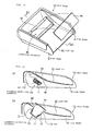
- Fig. 1 is a perspective view of a base frame of a seat including a passenger-protecting apparatus according to an embodiment.
- Fig. 2 is a perspective view of the passenger-protecting apparatus shown in Fig. 1, in an inflation state of a bag.
- Fig. 3 illustrates sectional views taken along line IIIA-IIIA indicated in Fig. 1 and IIIB-IIIB line indicated in Fig. 2.
- Fig. 4 is a sectional view of the base frame of a seat including the passenger-protecting apparatus, according to another embodiment.
- Fig. 5 is a perspective view of a base frame of a seat including the passenger-protecting apparatus, according to another embodiment.
- Fig. 6 is a perspective view of the base frame shown in Fig. 5, in the inflation state of the bag.
- Fig. 7 illustrates sectional views taken along line VIIA-VIIA indicated in Fig. 5 and line VIIB-VIIB indicated in Fig. 6.
- Fig. 8 is a perspective view of a base frame of a seat including the passenger-protecting apparatus, according to another embodiment.
- Fig. 9 is a perspective view of the base frame shown in Fig. 8, in the inflation state of the bag.
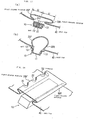
- Fig. 10 is an exploded perspective view of a base frame of a seat including the passenger-protecting apparatus, according to another embodiment.
- Fig. 11 illustrates sectional views of the base frame shown in Fig. 10, respectively, in the inflation and non-inflation states of the bag.
- Fig. 12 is a sectional view of a known example.
- Fig. 13 is a perspective view of a base frame of a seat including the passenger-protecting apparatus, according to another embodiment.
- Fig. 14 illustrates sectional views of the base frame shown in Fig. 13, respectively, in the inflation and non-inflation states of the bag.
- Fig. 15 is a perspective view of a base frame of a seat including the passenger-protecting apparatus, according to another embodiment.
- Fig. 16 illustrates sectional views of the base frame shown in Fig. 15, respectively, in the inflation and non-inflation states of the bag.
- Fig. 17 illustrates sectional views of another example structure of a pleat-shaped portion, respectively, in the inflation and non-inflation states of the bag.
- Fig. 18 is a sectional view of another example structure of a pleat-shaped portion.
- A frame constituting a seat of the automobile includes a
base frame 1 and a back frame (not shown) rotatably connected to the rear part of thebase frame 1 having a reclining device (not shown) interposed therebetween. The back frame has a headrest (not shown) fixed at the upper part thereof. - The
base frame 1 includes a pair of side frames 2 and 3 extending in the front-back direction along both sides of the seat. The side frames 2 and 3 have aseat pan 4 disposed over the front ends thereof. The rear ends of the side frames 2 and 3 are connected to each other with ashaft 5. - In the present embodiment, the
seat pan 4 extends relatively short in the front-back direction. Theseat pan 4 and theshaft 5 have a plurality of seat springs (hereinafter, simply referred to springs) 6 stretched over therebetween in a large number of rows. Eachspring 6 extends in the front-back direction while snaking its way from side to side like drawing a letter S and has one end connected to the rear end of theseat pan 4 and the other end connected to theshaft 5. - Although not shown, the
base frame 1 and the back frame have a seat cushion and a seat bag placed thereon, composed of urethane or the like. Theseat pan 4 and thesprings 6 support the seat cushion from below. In other words, in the present embodiment, theseat pan 4 and thesprings 6 constitute a supporting member of the seat cushion. The supporting member has a passenger-protectingapparatus 10 disposed under the front part thereof (a section extending from theseat pan 4 to the front ends of the springs 6). - The passenger-protecting
apparatus 10 includes a container-shapedretainer 11 opened upwards, aninflatable bag 12 folded and accommodated in theretainer 11, an inflator (not shown) inflating thebag 12 at the time of a car emergency, and alid 13 closing the opened part of the upper surface of theretainer 11. - The
retainer 11 extends in the left-right direction and both ends thereof are connected to the left and right side frames 2 and 3 withfixtures 14 such as bolts and nuts. Thebag 12 extends in the left-right direction inside of theretainer 11. Although not shown, the inflator is disposed within thebag 12 and fixed to the bottom of theretainer 11 via the lower part of thebag 12. When thebag 12 is inflated, thelid 13 is split when pushed by thebag 12. Theinflated bag 12 bulges out upwards while pushing open thelid 13 so as to push up the section from below, extending from theseat pan 4 to the front ends of thesprings 6. - Meanwhile, the passenger-protecting
apparatus 10 is shipped to a seat manufacturing facility in a previously unitized state in a passenger-protecting apparatus manufacturing facility. Then, in the seat manufacturing facility, the passenger-protectingapparatus 10 is installed under the front part of the supporting member of the seat cushion (theseat pan 4 and the springs 6) from the side of the lower surface of thebase frame 1 having the seat cushion already placed thereon. - Next, an operation of the passenger-protecting
apparatus 10 will be described. - Upon detection of a frontal car collision, the inflator discharges gas, so that the gas from the inflator inflates the
bag 12. As shown in Fig. 3(b), theinflated bag 12 pushes open thelid 13 and bulges out upwards so as to push upwards the section extending from theseat pan 4 to the front ends of thesprings 6. As a result, the front part of the seat cushion has a higher density because of being pushed up or pressed from below via theseat pan 4 and thesprings 6, thereby preventing or inhibiting the waist of a passenger from moving forwards. - Meanwhile, in the present embodiment, when pressed by the
inflated bag 12 from below, theseat pan 4 is subjected to a plastic deformation like forming an upward convex curve, thereby pressing upwards the seat cushion. In a seat including the passenger-protectingapparatus 10, since the passenger-protectingapparatus 10 is disposed under theseat pan 4 and thesprings 6 supporting the seat cushion, a seat-occupying person does not feel a foreign-body sensation and hence sits in the seat comfortably. - Also, on the occasion of, for example, fixing the passenger-protecting
apparatus 10 to the seat or maintaining it, its work can be conducted from the lower surface of the base frame without removing the seat cushion from above of theseat pan 4 and thesprings 6, thereby resulting in very satisfactory workability. - While the apparatus according to the present embodiment is constructed such that both the
seat pan 4 and thesprings 6 are pushed upwards by theinflated bag 12, the apparatus may be constructed as shown in Fig. 4, such that, when thesprings 6 are pushed upwards by thebag 12, the connection between the front ends of thesprings 6 and theseat pan 4 is released and only thesprings 6 are pushed upwards. Meanwhile, Fig. 4 is a longitudinal sectional view of the base frame of the seat having the above-described structure in the inflation state of the bag. - As the structure in which the front ends of the
springs 6 are disengaged from theseat pan 4 when thesprings 6 are pressed upwards, while a structure in which eachspring 6 has a downward L-shaped hook provided at the front end thereof such that the hook is hooked from above with a corresponding hole perforated in theseat pan 4 is illustrated by way of example, the structure is not limited to this. - With the above-described structure shown in Fig. 4, in comparison to the case where both the
seat pan 4 and thesprings 6 are pushed up by thebag 12, theinflated bag 12 suffices to have a low inner pressure. Therefore the inflator having a relatively low power can be adopted and the pressure strength of thebag 12 can be reduced. As a result, the structural cost of the apparatus can be reduced. - Figs. 5 and 6 are perspective views of a base frame of a seat including the passenger-protecting
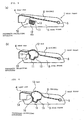
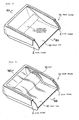
apparatus 10, according to another embodiment, and Figs. 7(a) and (b) are sectional views taken along lines VIIA-VIIA and VIIB-VIIB indicated in Fig. 6, respectively. Meanwhile, Fig. 5 and Fig. 7(a) illustrate the non-inflation state of the bag, and Fig. 6 and Fig. 7(b) illustrate the inflation state of the bag. - In the present embodiment, a
base frame 1A of the seat includes aseat pan 4A continuously extending in the front-back direction from both front ends to both rear ends of the left and right side frames 2 and 3. In other words, in the present embodiment, a seat cushion (not shown) is supported by a single sheet of theseat pan 4A from its front to rear ends. Theseat pan 4A has the passenger-protectingapparatus 10 disposed under the front part thereof. - In the present embodiment, when the
bag 12 is inflated, the front part of theseat pan 4A is pressed from below by thebag 12 and subjected to a plastic deformation like forming an upward convex curve as shown in Figs. 6 and 7(b), thereby pressing the front part of the seat cushion upwards. Meanwhile, the foregoing predetermined deformation area, deformed upwards like forming a convex curve, may be made thinner than its circumferential section or have a mesh or porous structure so as to accelerate the deformation. - Figs. 8 and 9 are perspective views of a
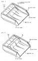
base frame 1B of a seat including the passenger-protectingapparatus 10, according to another embodiment. Meanwhile, Fig. 8 illustrates the non-inflation state of the bag and Fig. 9 illustrates the inflation state of the bag. - In the present embodiment too, a supporting member supporting a seat cushion (not shown) from its front to rear ends is formed from a single sheet of a
seat pan 4B, which has the passenger-protectingapparatus 10 disposed under the front part thereof. As shown in Fig. 8, in the present embodiment, a slit 4a serving as deformation-accelerating means extends along the periphery of a predetermined deformation area, deformed when pressed from below by theinflated bag 12, of the front part of theseat pan 4B. While the slit has a C-shape so as to surround three sides of the front and the left and right sides of the predetermined deformation area in the present embodiment, it may surround three sides of the rear and the left and right sides. Also, the predetermined deformation area may have slits along two sides along the front and rear ends thereof, or the predetermined deformation area may have slits along the left and right sides thereof. - In the present embodiment, as shown in Fig. 9, when the
bag 12 is inflated, thebag 12 presses the area of theseat pan 4B surrounded by the slit 4a from below. Accordingly the area opens out upwards like forming a flap (4b) shape so as to press the seat cushion upwards. The upward opening out of theflap 4b is smoothly and quickly achieved. - Fig. 10 is an exploded perspective view of a base frame 1C of a seat including the passenger-protecting
apparatus 10, according to another embodiment, and Figs. 11(a) and (b) are sectional views of the base frame 1C taken along line XI-XI indicated in Fig. 10, respectively, in the inflation and non-inflation states of the bag. - In the present embodiment too, a supporting member supporting a seat cushion (not shown) from its front to rear ends is formed from a single sheet of a
seat pan 4C, which has the passenger-protectingapparatus 10 disposed under the front part thereof. In the present embodiment, theseat pan 4C has anopening 4d arranged at the front part thereof, allowing theinflated bag 12 to pass therethrough towards the seat cushion. Aplate 4e is arranged so as to cover theopening 4d. - The
plate 4e is overlaid on theopening 4d from the side of the seat cushion, and its periphery is retained with or lightly connected to the periphery of theopening 4d. When thebag 12 is inflated, theplate 4e is detached from theseat pan 4C while being pushed by thebag 12 and moves upwards. As means for retaining or lightly connecting theplate 4e with or to theseat pan 4C, while a flat fastener such as a magic tape (registered trade mark), bonding with an adhesive or a double-side tape, riveting with a low strength, fitting with a low strength, spot-welding with a low strength, and the like are listed by way of example, the means is not limited to the above ones. While theplate 4e preferably covers theoverall opening 4d, it may cover a part of theopening 4d. The overall or a part of theplate 4e may have a hole or a slit perforated therein. - In the present embodiment, when the
bag 12 is inflated, thebag 12 passes through theopening 4d while pushing up theplate 4e and presses the seat cushion lying above theseat pan 4C. Hence, the front part of the seat cushion is quickly pushed up or made hard by thebag 12. - While the
base frame 1 shown in Figs. 1 to 3 has the seat springs 6 stretched over in the front-rear direction of the seat, the seat springs 6 may be stretched over in the left-right direction of the seat. Fig. 13 is a perspective view of a base frame ID having the above-described structure, and Fig. 14 illustrates sectional views taken along line XIV-XIV indicated in Fig. 13. Meanwhile, Fig. 14(a) illustrates the non-inflation state of the bag and Fig. 14(b) illustrates the inflation state of the bag. - The
base frame 1D has the same structure as that of the foregoingbase frame 1 shown in Figs. 1 to 3, except that the left and right side frames 2 and 3 have seat springs 6A stretched over therebetween, and the same reference characters in Figs. 13 and 14 as those in Figs. 1 to 3 represent the same parts. Meanwhile, Eachspring 6A extends in the left-right direction while snaking its way back and forth like drawing a letter S and both ends thereof respectively connected to the side frames 2 and 3. - With a positional relation of being located around between the rear end of the
seat pan 4 and thespring 6A close to theseat pan 4, the passenger-protectingapparatus 10 is disposed under theseat pan 4 and thespring 6A. - In the present embodiment too, when the inflator of the passenger-protecting
apparatus 10 discharges gas, thebag 12 is inflated and pushes theseat pan 4 and thespring 6A close to theseat pan 4 upwards as shown in Fig. 14(b). As a result, the front part of the seat cushion has a higher density because of being pushed up or pressed from below via theseat pan 4 and thesprings 6A, thereby preventing or inhibiting the waist of a passenger from moving forwards. - Meanwhile, the
springs 6A may be likewise formed such that the connection of both ends thereof to the side frames 2 and 3 is released when pushed upwards by theinflated bag 12. Also, the apparatus may be constructed such that thebag 12 inflates out towards the seat cushion while passing through between the rear end of theseat pan 4 and thespring 6A close to theseat pan 4 or between the mutuallyadjacent springs 6A. - Fig. 15 is a perspective view of a base frame of a seat including the passenger-protecting
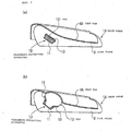
apparatus 10, according to another embodiment, and Fig. 16 illustrates sectional views taken along line XVI-XVI indicated in Fig. 15. Meanwhile, Fig. 16(a) illustrates the non-inflation state of the bag and Fig. 16(b) illustrates the inflation state of the bag. - With a
base frame 1E according to the present embodiment, a supporting member supporting a seat cushion (not shown) from its front to rear ends is formed from a single sheet of theseat pan 4E, which has the passenger-protectingapparatus 10 disposed under the front part thereof. As shown in Fig. 15, in the present embodiment, pleat-shapedportions 20 serving as deformation-accelerating means are formed along the periphery of a predetermined deformation area, deformed when pressed from below by theinflated bag 12, of the front part of theseat pan 4E. - As shown in Fig. 16(a), each pleat-shaped
portion 20 is formed such that a section extending along the periphery of the predetermined deformation area (a section between the predetermined deformation area and a circumferential portions of the predetermined deformation area) of theseat pan 4E is folded back on the upper side of the circumferential portion like providing a slack to the section. Meanwhile, while being folded back only once in Fig. 16(a), the section may be folded back a plurality of times in a zigzag pattern. - In the present embodiment, while being respectively disposed along the front and rear ends of the predetermined deformation area as shown in the figure, the pleat-shaped
portions 20 may be disposed along the left and right side ends of the predetermined deformation area. Also, the pleat-shaped portion may be disposed all around or partially around the predetermined deformation area. - In the present embodiment, when the
bag 12 is inflated and presses the predetermined deformation area of theseat pan 4E from below, as shown in Figs. 16(a) and (b), the pleat-shapedportions 20 are deformed like extending upwards and accelerates the predetermined deformation area to bulge upwards. With this, the predetermined deformation area bulges upwards smoothly and quickly and early presses the seat cushion upwards. - Meanwhile, by selecting the shape, the size, the arrangement, and so forth of the pleat-shaped
portion 20 where appropriate, for example, the bulging shape, the bulging direction, and the bulging height of the predetermined deformation area from the upper surface of theseat pan 4E can be controlled. Fig. 17 shows sectional views of a major part of theseat pan 4E, illustrating example of pleat-shaped portions having the above-described structure. Meanwhile, Fig. 17(a) illustrates the non-inflation state of the bag and Fig. 17(b) illustrates the inflation state of the bag. - In the present embodiment too, the predetermined deformation area of the
seat pan 4E has pleat-shapedportions portions - With a positional relation in which a middle position in the front-back direction, of the base end of the
bag 12 substantially coincides with a middle position in the front-back direction, between base ends (folded back portions serving as boundaries between the pleat-shapedportions portions apparatus 10 is disposed under the predetermined deformation area. - In the present embodiment, a distance dr from the middle position in the front-back direction, of the base end of the bag 12 (hereinafter, simply referred to as middle position) to the rear end of the rear pleat-shaped
portion 20R is greater than a distance df from the middle position to the front end of the front pleat-shapedportion 20F. That is, a folded amount of the rear pleat-shapedportion 20R onto the upper surface of theseat pan 4E is greater than a folded amount of the front pleat-shapedportion 20F onto theseat pan 4E. - With the above-described structure, when the
bag 12 is inflated and presses the predetermined deformation area from below, the rear pleat-shapedportion 20R extends out upwards on a larger scale than the front pleat-shapedportion 20F. As a result, as shown in Fig. 17(b), the predetermined deformation area bulges out in a slanting rear-upward direction, that is, in a direction coming closer to the waist of a sitting passenger. - Meanwhile, the bulging shape and the others from the upper surface of the predetermined deformation area of the
seat pan 4E can be likewise controlled by adjusting the stiffness of the pleat-shaped portions by providing openings such as slits or thin wall portions, or ribs or thick wall portions to the pleat-shaped portions. Fig. 18 is a perspective view illustrating example of pleat-shaped portions having the above-described structure. - In the present embodiment too, the predetermined deformation area of the
seat pan 4E has a pleat-shapedportion 20F' and the pleat-shapedportion 20R disposed along the front and rear ends thereof, respectively. In the present embodiment, the front pleat-shapedportion 20F' has a plurality of small bore-shapedopenings 22 bored therein. With this arrangement, the stiffness of the pleat-shapedportion 20F' is smaller than that of the rear pleat-shapedportion 20R. - Accordingly, when the
bag 12 is inflated and presses the predetermined deformation area from below, the pleat-shapedportion 20F' extends more quickly and on a larger scale than the pleat-shapedportion 20R, so that the predetermined deformation area bulges out upwards while inclining rearwards so as to oppose to the forward movement of the sitting passenger. - Any of the foregoing embodiments is merely an example of the present invention, and the present invention is not limited to the embodiments shown in the figures. For example, while the
retainer 11 of the passenger-protectingapparatus 10 is supported with the left and right side frames in each of the foregoing embodiments, theretainer 11 may be directly fixed to the lower surface of the supporting member including the seat pan. With this structure, the distance between the passenger-protectingapparatus 10 and the waist of a seat-occupying person is small, whereby the inflated bag quickly constrains the movement of the waist of the passenger.
Claims (9)
- A passenger-protecting apparatus, comprising:a bag which is disposed under the front part of a supporting member supporting a seat cushion and which is inflatable so as to push up the supporting member from below; andan inflator inflating the bag at the time of a car emergency,wherein the front part of the seat cushion is pressed from below when the front part of the supporting member is pushed up by the inflated bag.
- The passenger-protecting apparatus according to Claim 1, wherein the supporting member is a seat pan and seat springs, and when the bag is inflated, the seat pan and the seat springs are pushed upwards.
- The passenger-protecting apparatus according to Claim 1 or 2, wherein the supporting member is seat springs connected to a seat pan and extending in the front-back direction, and
wherein, when the bag is inflated, the connection between the front ends of the seat springs and the seat pan is released and the front parts of the seat springs are pushed upwards. - The passenger-protecting apparatus according to Claim 1, wherein the supporting member is seat springs extending in the left-right direction and having both ends thereof connected to the frame section of a seat, and
wherein, when the bag is inflated, the connection between both ends of the seat springs and the frame section is released and the seat springs are pushed upwards. - The passenger-protecting apparatus according to Claim 1, wherein the supporting member is a seat pan,
wherein the seat pan is pushed upward while being deformed when the bag is inflated. - The passenger-protecting apparatus according to any one of claims 2, 3 or 5, wherein the seat pan has deformation-accelerating means provided therein for accelerating the upward deformation thereof.
- The passenger-protecting apparatus according to Claim 6, wherein the deformation-accelerating means is a slit disposed along the periphery of a predetermined deformation area of the seat pan.
- The passenger-protecting apparatus according to Claim 6, wherein the deformation-accelerating means is a pleat-shaped portion disposed along the periphery of the predetermined deformation area of the seat pan.
- The passenger-protecting apparatus according to Claim 1, wherein the supporting member is a seat pan,
wherein the seat pan has an opening perforated therein above the bag, for allowing the inflated bag to pass upwards therethrough, and a plate disposed thereon so as to cover the opening, and
wherein the plate is pushed upwards when the bag is inflated.
Applications Claiming Priority (2)
| Application Number | Priority Date | Filing Date | Title |
|---|---|---|---|
| JP2004355581 | 2004-12-08 | ||
| JP2005021611A JP2006188198A (en) | 2004-12-08 | 2005-01-28 | Occupant crash protection device |
Publications (1)
| Publication Number | Publication Date |
|---|---|
| EP1669240A1 true EP1669240A1 (en) | 2006-06-14 |
Family
ID=35997670
Family Applications (1)
| Application Number | Title | Priority Date | Filing Date |
|---|---|---|---|
| EP05022345A Withdrawn EP1669240A1 (en) | 2004-12-08 | 2005-10-13 | Passenger-protecting apparatus |
Country Status (3)
| Country | Link |
|---|---|
| US (1) | US20060119149A1 (en) |
| EP (1) | EP1669240A1 (en) |
| JP (1) | JP2006188198A (en) |
Families Citing this family (18)
| Publication number | Priority date | Publication date | Assignee | Title |
|---|---|---|---|---|
| JP2006199271A (en) * | 2004-12-24 | 2006-08-03 | Tkj Kk | Occupant restraint system |
| WO2006132990A1 (en) * | 2005-06-03 | 2006-12-14 | Abc Group, Inc. | Active bolster |
| US8240758B2 (en) * | 2006-03-27 | 2012-08-14 | Nissan North America, Inc. | Deformable seat pan for a tiltable vehicle seat |
| JP4889622B2 (en) * | 2007-12-11 | 2012-03-07 | オートリブ ディベロップメント エービー | Vehicle seat and airbag device |
| JP5675293B2 (en) * | 2010-11-17 | 2015-02-25 | 芦森工業株式会社 | Vehicle seat equipped with an airbag device |
| JP5958129B2 (en) * | 2012-07-12 | 2016-07-27 | 豊田合成株式会社 | Seat cushion airbag device |
| JP5780265B2 (en) * | 2013-06-07 | 2015-09-16 | トヨタ自動車株式会社 | Vehicle seat with built-in cushion airbag device |
| US9199560B2 (en) * | 2013-09-13 | 2015-12-01 | Ford Global Technologies, Llc | Self-adjusting seat stiffness system |
| KR102207570B1 (en) * | 2014-09-26 | 2021-01-26 | 현대모비스 주식회사 | Cushion of seat cushion air bag device |
| US9994138B2 (en) * | 2015-12-02 | 2018-06-12 | Ford Global Technologies, Llc | Seat with deployable plastic beam |
| JP6927059B2 (en) * | 2018-01-18 | 2021-08-25 | トヨタ自動車株式会社 | Vehicle seat |
| US11059403B2 (en) * | 2018-05-17 | 2021-07-13 | Toyota Motor Engineering & Manufacturing North America, Inc. | Reinforced rear seat assemblies for vehicles |
| JP7056508B2 (en) * | 2018-10-19 | 2022-04-19 | 豊田合成株式会社 | Vehicle occupant protection device |
| JP7222110B2 (en) * | 2019-09-23 | 2023-02-14 | オートリブ ディベロップメント エービー | Airbag device and vehicle seat |
| US11077817B1 (en) | 2020-01-23 | 2021-08-03 | Ford Global Technologies, Llc | Airbag assembly inflatable from seat bottom |
| JP7276224B2 (en) * | 2020-03-31 | 2023-05-18 | 豊田合成株式会社 | passenger protection device |
| US11247629B1 (en) * | 2020-08-17 | 2022-02-15 | Ford Global Technologies, Llc | Vehicle airbag |
| KR20250019068A (en) | 2022-05-31 | 2025-02-07 | 아우토리브 디벨롭먼트 아베 | Vehicle Occupant Protection Devices |
Citations (5)
| Publication number | Priority date | Publication date | Assignee | Title |
|---|---|---|---|---|
| JPH10217818A (en) | 1997-01-31 | 1998-08-18 | Ikeda Bussan Co Ltd | Seat for vehicle |
| US20030052519A1 (en) * | 2001-09-14 | 2003-03-20 | The Boeing Company | Seat assembly having a seat repositioning device and an associated method |
| EP1369315A1 (en) * | 2002-06-04 | 2003-12-10 | Takata Corporation | Occupant protecting device in vehicle seat |
| WO2004030980A1 (en) * | 2002-10-01 | 2004-04-15 | Dalphimetal Ltd. | Vehicle seat with a pelvis energy management device |
| US20040222680A1 (en) * | 2003-05-09 | 2004-11-11 | Trw Automotive Gmbh | Inflatable seat restraint cushion |
Family Cites Families (8)
| Publication number | Priority date | Publication date | Assignee | Title |
|---|---|---|---|---|
| US3473824A (en) * | 1967-08-18 | 1969-10-21 | Eaton Yale & Towne | Safety device |
| US5082326A (en) * | 1989-04-28 | 1992-01-21 | Okamoto Industries, Inc. | Vehicle seat with automatic adjustment mechanisms utilizing inflatable air bags |
| WO1997045297A1 (en) * | 1996-05-31 | 1997-12-04 | Nissan Motor Co., Ltd. | Air bag apparatus for seat of vehicle |
| DE19813054A1 (en) * | 1998-03-25 | 1999-10-07 | Daimler Chrysler Ag | Airbag device for a motor vehicle |
| JP2000001153A (en) * | 1998-06-16 | 2000-01-07 | Fuji Heavy Ind Ltd | Vehicle seat with airbag |
| GB2357466B (en) * | 1999-12-21 | 2003-04-02 | Autoliv Dev | Improvements in or relating to a vehicle seat |
| JP4269826B2 (en) * | 2003-03-12 | 2009-05-27 | タカタ株式会社 | Crew protection device |
| US20050067209A1 (en) * | 2003-09-30 | 2005-03-31 | Takata Corporation | Passenger protecting device |
-
2005
- 2005-01-28 JP JP2005021611A patent/JP2006188198A/en not_active Withdrawn
- 2005-10-13 EP EP05022345A patent/EP1669240A1/en not_active Withdrawn
- 2005-12-01 US US11/292,053 patent/US20060119149A1/en not_active Abandoned
Patent Citations (5)
| Publication number | Priority date | Publication date | Assignee | Title |
|---|---|---|---|---|
| JPH10217818A (en) | 1997-01-31 | 1998-08-18 | Ikeda Bussan Co Ltd | Seat for vehicle |
| US20030052519A1 (en) * | 2001-09-14 | 2003-03-20 | The Boeing Company | Seat assembly having a seat repositioning device and an associated method |
| EP1369315A1 (en) * | 2002-06-04 | 2003-12-10 | Takata Corporation | Occupant protecting device in vehicle seat |
| WO2004030980A1 (en) * | 2002-10-01 | 2004-04-15 | Dalphimetal Ltd. | Vehicle seat with a pelvis energy management device |
| US20040222680A1 (en) * | 2003-05-09 | 2004-11-11 | Trw Automotive Gmbh | Inflatable seat restraint cushion |
Also Published As
| Publication number | Publication date |
|---|---|
| US20060119149A1 (en) | 2006-06-08 |
| JP2006188198A (en) | 2006-07-20 |
Similar Documents
| Publication | Publication Date | Title |
|---|---|---|
| EP1669240A1 (en) | Passenger-protecting apparatus | |
| JP6926959B2 (en) | Vehicle seat | |
| EP1240049B1 (en) | A vehicle seat | |
| JP4453176B2 (en) | Bench seat for vehicle | |
| US7784866B2 (en) | Occupant restraint device | |
| EP1800941B1 (en) | Passenger protection device | |
| KR20030095879A (en) | Anti submarine seat for automobile | |
| CN111086478A (en) | Side airbag device | |
| EP1942034A1 (en) | Occupant restraint device and seat | |
| EP1925507A1 (en) | Occupant restraining system | |
| US6575494B1 (en) | Active head restraint with gas bag module | |
| JP4709153B2 (en) | Lumbar restraint airbag device and seat cushion device using the same | |
| WO2008001548A1 (en) | Occupant restraint device and vehicle seat | |
| US20060175880A1 (en) | Occupant protection device | |
| JP4165217B2 (en) | Crew protection device | |
| JP3181378B2 (en) | Automotive airbag equipment | |
| JP2008238955A (en) | Vehicular seat | |
| JP7614904B2 (en) | Vehicle seat | |
| JP7757799B2 (en) | occupant restraint system | |
| JP4503524B2 (en) | Arrangement structure of airbag device | |
| JP2007015466A (en) | Occupant crash protection device | |
| JP2026062423A (en) | Vehicle seats | |
| JP2004168273A (en) | Shock absorber | |
| JP2007290535A (en) | Vehicular seat | |
| JP2003025887A (en) | Seat for vehicle |
Legal Events
| Date | Code | Title | Description |
|---|---|---|---|
| PUAI | Public reference made under article 153(3) epc to a published international application that has entered the european phase |
Free format text: ORIGINAL CODE: 0009012 |
|
| AK | Designated contracting states |
Kind code of ref document: A1 Designated state(s): AT BE BG CH CY CZ DE DK EE ES FI FR GB GR HU IE IS IT LI LT LU LV MC NL PL PT RO SE SI SK TR |
|
| AX | Request for extension of the european patent |
Extension state: AL BA HR MK YU |
|
| 17P | Request for examination filed |
Effective date: 20061122 |
|
| 17Q | First examination report despatched |
Effective date: 20061213 |
|
| AKX | Designation fees paid |
Designated state(s): DE FR GB SE |
|
| RIN1 | Information on inventor provided before grant (corrected) |
Inventor name: KUMAGAI, MASAYOSHI Inventor name: YOSHIKAWA, HIROMICHI |
|
| STAA | Information on the status of an ep patent application or granted ep patent |
Free format text: STATUS: THE APPLICATION IS DEEMED TO BE WITHDRAWN |
|
| 18D | Application deemed to be withdrawn |
Effective date: 20081115 |