EP1668622B1 - Method and system for controlling an illuminating apparatus - Google Patents
Method and system for controlling an illuminating apparatus Download PDFInfo
- Publication number
- EP1668622B1 EP1668622B1 EP04770043.0A EP04770043A EP1668622B1 EP 1668622 B1 EP1668622 B1 EP 1668622B1 EP 04770043 A EP04770043 A EP 04770043A EP 1668622 B1 EP1668622 B1 EP 1668622B1
- Authority
- EP
- European Patent Office
- Prior art keywords
- luminous intensity
- circumstance
- luminance
- controlling
- luminance controlling
- Prior art date
- Legal status (The legal status is an assumption and is not a legal conclusion. Google has not performed a legal analysis and makes no representation as to the accuracy of the status listed.)
- Expired - Lifetime
Links
Images


Classifications
-
- G—PHYSICS
- G09—EDUCATION; CRYPTOGRAPHY; DISPLAY; ADVERTISING; SEALS
- G09G—ARRANGEMENTS OR CIRCUITS FOR CONTROL OF INDICATING DEVICES USING STATIC MEANS TO PRESENT VARIABLE INFORMATION
- G09G3/00—Control arrangements or circuits, of interest only in connection with visual indicators other than cathode-ray tubes
- G09G3/20—Control arrangements or circuits, of interest only in connection with visual indicators other than cathode-ray tubes for presentation of an assembly of a number of characters, e.g. a page, by composing the assembly by combination of individual elements arranged in a matrix no fixed position being assigned to or needed to be assigned to the individual characters or partial characters
- G09G3/34—Control arrangements or circuits, of interest only in connection with visual indicators other than cathode-ray tubes for presentation of an assembly of a number of characters, e.g. a page, by composing the assembly by combination of individual elements arranged in a matrix no fixed position being assigned to or needed to be assigned to the individual characters or partial characters by control of light from an independent source
- G09G3/3406—Control of illumination source
- G09G3/342—Control of illumination source using several illumination sources separately controlled corresponding to different display panel areas, e.g. along one dimension such as lines
- G09G3/3426—Control of illumination source using several illumination sources separately controlled corresponding to different display panel areas, e.g. along one dimension such as lines the different display panel areas being distributed in two dimensions, e.g. matrix
-
- G—PHYSICS
- G09—EDUCATION; CRYPTOGRAPHY; DISPLAY; ADVERTISING; SEALS
- G09G—ARRANGEMENTS OR CIRCUITS FOR CONTROL OF INDICATING DEVICES USING STATIC MEANS TO PRESENT VARIABLE INFORMATION
- G09G2320/00—Control of display operating conditions
- G09G2320/06—Adjustment of display parameters
- G09G2320/0626—Adjustment of display parameters for control of overall brightness
-
- G—PHYSICS
- G09—EDUCATION; CRYPTOGRAPHY; DISPLAY; ADVERTISING; SEALS
- G09G—ARRANGEMENTS OR CIRCUITS FOR CONTROL OF INDICATING DEVICES USING STATIC MEANS TO PRESENT VARIABLE INFORMATION
- G09G2330/00—Aspects of power supply; Aspects of display protection and defect management
- G09G2330/02—Details of power systems and of start or stop of display operation
- G09G2330/021—Power management, e.g. power saving
-
- G—PHYSICS
- G09—EDUCATION; CRYPTOGRAPHY; DISPLAY; ADVERTISING; SEALS
- G09G—ARRANGEMENTS OR CIRCUITS FOR CONTROL OF INDICATING DEVICES USING STATIC MEANS TO PRESENT VARIABLE INFORMATION
- G09G2360/00—Aspects of the architecture of display systems
- G09G2360/14—Detecting light within display terminals, e.g. using a single or a plurality of photosensors
- G09G2360/144—Detecting light within display terminals, e.g. using a single or a plurality of photosensors the light being ambient light
Definitions
- the present invention relates to a luminance controlling system, particularly to an adaptive system that could automatically adjust its own luminous intensity according to the luminous intensity of the circumstance.
- Electronic devices such as mobile phone, PDA (Personal Digital Assistant), pager, etc. usually have a display screen, which is mostly a liquid crystal displaying apparatus that could make the content to be displayed visible by providing backlights when the luminous intensity of the circumstance is not high enough. Meanwhile, these electronic devices such as mobile phone and PDA (Personal Digital Assistant) may also have a data inputting apparatus comprising a set of keys, and the devices make the keypad visible through backlights when the luminous intensity of the circumstance is not high enough.
- Fig. 1 is the prior art digital luminance controlling system.
- the system is a technical solution disclosed in the U.S. Patent US5, 760, 760 (granted on June 2, 1998 ), comprising a light sensing apparatus 110, a digital luminance controlling apparatus 120, a light source controlling apparatus 130 and a group of light sources 140, with the digital luminance controlling apparatus further comprising an analog-to-digital converter (ADC) 122, a digital signal processor (DSP) 124 and a memory 126.
- ADC analog-to-digital converter
- DSP digital signal processor
- the light sensing apparatus 110 When the light sensing apparatus 110 detects the luminous intensity of the circumstance, it sends an signal of the luminous intensity of the circumstance to the digital luminance controlling apparatus 120, and the analog signal is converted into digital signal in accordance with a preset sampling frequency by the analog-to-digital converter 122 and the digital signal is sent to the digital signal processor 124, and the digital signal processor 124 reads the luminance level in the memory 126 according to the digital luminous intensity signal and converts it into a luminance controlling signal to be sent to the light control device 130 which adjusts the luminance of the light source according to the received luminance controlling signal.
- Fig. 2 is the light source controlling apparatus of the prior art digital luminance controlling system.
- the device is a technical solution disclosed in the British Patent GB2, 365, 691 (published on February 20, 2002 ), comprising a group of selection switches (S 1 , S 2 , ..., S N ) and M groups of resistors (R 11 , R 12 , ..., R 1N ; R 21 , R 22 , ..., R 2N ; ...; R M1 , R M2 , ..., R MN ), with the number of resistors in each group of resistors depending on the number of selection switches, i.e. , on the number of luminance levels.
- the group of selection switches and M groups of resistors are connected to a light source, i.e., an illuminating apparatus comprising a group of luminaries (L 1 , L 2 , ..., L M )(such as lightemitting diodes), in such a manner that each switch, such as S 1 , is connected to a group of resistors (R 11 , R 21 , ..., R M1 ) and the luminaries (L 1 , L 2 , ..., L M ), wherein the number of resistors in the group of resistors depends on the number of the luminaries, and wherein the resistors are directly connected to the luminaries.
- a light source i.e., an illuminating apparatus comprising a group of luminaries (L 1 , L 2 , ..., L M )(such as lightemitting diodes), in such a manner that each switch, such as S 1 , is connected to a group of resistors (R 11 , R 21
- Document EP1227642A1 discloses a hand-held electronic device provided with at least one microprocessor, such as a mobile telephone, a personal computer or the like.
- the hand-held electronic device comprises a control means, at least one first light source and at least one a second light source each of which being associated with said control means , adapted to control the light intensity of the first light source independently from the second light source.
- said control means is adapted to variably adjust the light intensity, and in that said control means is adapted to control the light intensity depending on ambient light conditions.
- Document WO00/41378 discloses a handportable device which comprises a user interface (1), a light detector (21) for detecting the light incident on at least part of the user interface, a comparator for comparing the light detected with a given threshold and control means for controlling an illuminator for illuminating the user interface in dependence upon the output of the comparator.
- the light detector is positioned to detect light incident on the device, which light is the sum of ambient light and the light from the illuminator.
- Document US2001/0013854A1 discloses an electronic apparatus with backlit display and input device allowing reduced power consumption while maintaining necessary brightness is disclosed.
- a mode detecting section detects a currently set operation mode when performing a function. The brightness of the backlighting is controlled depending on the currently set operation mode. In the case of a data input mode, the brightness of the backlighting is reduced.
- an improved luminance controlling system is needed, which could change the luminance more smoothly with the change of the luminous intensity of the circumstance so as to achieve the objects of reducing power consumption and saving cost.
- a first aspect of the invention provides a system for controlling an illuminating apparatus as claimed in claim 1.
- a second aspect of the invention provides a method for controlling an illuminating apparatus as claimed in claim 3.
- An embodiment provides an improved digital luminance controlling system, in a light source controlling apparatus thereof, the resistor and the luminaries are connected by a switch, thus the luminance of the illuminated area could be controlled by selecting the number of the ignited luminaries. By reducing the number of the ignited luminaries, the power consumption could be reduced.
- Another embodiment provides an improved digital luminance controlling system, and a digital luminance controlling apparatus thereof compares two successively detected values of the luminous intensity of the circumstance. If the difference between the values is smaller than a predetermined value, the sampling frequency is decreased, and if the difference is greater than another predetermined value, the sampling frequency is increased. By adjusting the sampling frequency timely, the luminance controlling system could operate less frequently and thereby the power consumption could be reduced.
- a further embodiment provides an analog luminance controlling system, comprising a light sensing apparatus, an analog luminance controlling apparatus and a group of light sources.
- the light sensing apparatus detects the luminous intensity of the circumstance, it sends an signal of the luminous intensity of the circumstance to the analog luminance controlling apparatus, and the signal of the luminous intensity of the circumstance is converted into luminance controlling signal according to a preset magnification by the analog luminance controlling apparatus, and the controlling signal is applied to the light source in the form of current or voltage to adjust the luminance of the light source.
- the luminance controlling apparatus works in an analog manner, real-time luminance adjustment could be realized, and thus the power consumption is reduced.
- the analog-to-digital converter (ADC), the digital signal processor (DSP), the memory and the light source controlling apparatus are not needed any more, the objects of saving costs and further reducing power consumption can be achieved.
- Fig. 3 is the digital luminance controlling apparatus of an embodiment of the present invention.
- a group of selection switches S 1 , S 2 , ..., S N
- the resistors R 1 , R 2 , ..., R N
- the luminaries L 1 , L 2 , ..., L N
- a corresponding number of luminaries can be set to the ignited state by setting different numbers of switches to the connection state, and thereby to make the light source comprising the group of luminaries provide the desired luminance in the illuminated area.
- the embodiment could greatly reduce the number of resistors needed and the complexity of the circuits while maintaining the same luminance controlling level, thus the power consumption is reduced.
- Fig. 4 is the schematic plan view of a group of luminaries composing the illuminating apparatus of an embodiment of the present invention.
- an illuminating apparatus comprising a group of nine luminaries (L 41 , L 42 , ..., L 49 ), and the arrangement of the luminaries is shown in the figure. It can be seen from the figure that luminaries in different positions contribute differently to the general luminous intensity of the illuminated area under the same illuminating conditions (the same rated power, the same current, etc.), for example, L 45 contributes more than L 44 , and L 44 contributes more than L 41 and so on.
- the light source comprising L 42 +L 44 +L 46 +L 48 could achieve the same general luminous intensity as the light source comprising L 41 +L 43 +L 45 +L 47 +L 49 .
- luminaries of different rated illuminating power could be selected according to the different contribution rate of each luminary to the general luminous intensity, and resistors of different resistance values could be selected to be connected to different luminaries, thereby, different luminaries could have different luminous intensity under the same luminance controlling signal.
- some electronic devices such as mobile phone, PDA (Personal Digital Assistant) etc.
- Fig. 5 is a digital luminance controlling apparatus of another embodiment of the present invention
- the digital luminance controlling apparatus is an improvement based on the technical solution of Fig. 3 .
- a group of switches(S N+1 , S N+2 , ..., S N+M ) is added between M groups of resistors (R 11 , R 12 , ..., R 1N ; R 21 , R 22 , ..., R 2N ; ...; R M1 , R M2 , ...R MN ) and luminaries (L 1 , L 2 , ..., L M ), thus compared with the technical solution of Fig. 2 , the present embodiment could have more luminance controlling levels available for selection, so that the luminance could be changed more smoothly with the change of the luminous intensity of the circumstance so as to achieve the object of reducing power consumption.
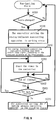
- Fig. 6 is the flow chart of the operating process of the digital luminance controlling system of an embodiment of the present invention.
- the display screens of electronic devices such as mobile phone, PDA (Personal Digital Assistant) have different states.
- states there are two different types of states, i.e., the igniting state and the non-igniting state, wherein the igniting state is the working state that needs manual intervention and the non-igniting state includes the stand-by state and working state that does not need manual intervention, etc.
- the working state that does not need manual intervention is, for example, the state of data exchanging with the computer or network and the state of calling for a long time, etc.
- the electronic devices are usually in the non-igniting state, and when the state changes to an igniting one (step S620), the luminance controlling system first detects the luminous intensity of the circumstance (step S630) and then preliminarily sets the luminous intensity of the illuminating apparatus of the system according to the luminous intensity of the circumstance (step S642) while initializing the luminous intensity of the circumstance sampling frequency (step S646).
- the luminous intensity of the illuminating apparatus of the system could be set to zero according to the luminous intensity of the circumstance, i.e., not using the illuminating apparatus of the system.
- step S650 when the next sampling time is up (step S650), it is determined whether the electronic device is in the igniting state (step S660). If it is, again the luminance controlling system detects the luminous intensity of the circumstance (step S670) and sets the luminous intensity of the illuminating apparatus of the system according to the luminous intensity of the circumstance (step S680), and if it is not in the igniting state, the whole system is set to the non-igniting state.
- each new sampled value of the luminous intensity of the circumstance is compared with its previous sampled value of the luminous intensity of the circumstance (step S690). If the absolute value of the difference is smaller than a certain preset value Value 1 (e.g., 2 lux), the sampling frequency of the luminous intensity of the circumstance is reduced based on the difference (step S696); if the absolute value of the difference is greater than a certain preset value Value 2 (e.g., 10 lux), the sampling frequency of the luminous intensity of the circumstance is increased based on the difference (step S692), wherein Value 2 >Value 1; and if the absolute value of the difference is between the preset value Value1 and Value2, the sampling frequency of the luminous intensity of the circumstance remains the same(step S694).
- a certain preset value Value 1 e.g., 2 lux
- Value 2 e.g. 10 lux
- step S650 return to step S650 according to the adjusted sampling frequency of the luminous intensity of the circumstance.
- the next sampling time is up, it is determined again whether the electronic device is in the igniting state, and the above process will be repeated.
- Fig. 7 is the analog luminance controlling system of an embodiment of the present invention.
- the analog luminance controlling system comprises a light sensing apparatus 710, an analog luminance controlling apparatus 720 and a group of light sources 730.
- the analog luminance controlling apparatus further comprises a mapping amplifying circuit 726, a controller 722 with timing function and a switch 724.
- the light sensing apparatus 710 detects the luminous intensity of the circumstance, it sends a signal of the luminous intensity of the circumstance to the analog luminance controlling apparatus 720.
- the controller 722 with timing function sends an activating signal to set the switch 724 to the connection state, then the signal of the luminous intensity of the circumstance is converted into luminance controlling signal according to the preset reverse magnification by the analog luminance controlling apparatus and the controlling signal is applied to the light source in the form of current or voltage to adjust the luminance of the light source.
- the reverse magnification of the present embodiment is shown in the curve 760 of the figure.
- the curve is continuously changed in real-time while the higher the luminous intensity of the circumstance is, the lower the luminous intensity of the system itself.
- the reverse magnification could be preset by the manufacturer of the electronic device or by the user.
- the luminance controlling system having an reverse relationship with the luminous intensity of the circumstance could be applied to electronic devices providing backlights, such as the liquid crystal display screen of the mobile phone, etc., wherein the higher the luminous intensity of the circumstance is, the lower the backlights intensity of the display screen.
- the luminous intensity of the circumstance is greater than 100 lux, the backlights intensity of the display screen is zero, i.e., the illuminating apparatus of the system is not in use.
- the luminance controlling signal sent by the digital luminance controlling apparatus and the luminous intensity of the circumstance could also have a reverse relationship, and the reverse relationship could also be preset by the manufacturer of the electronic device or by the user, except that it is a non-continuous grading distribution.
- luminaries of different rated illuminating power could be selected according to different contribution rate of each luminary to the general luminous intensity of the illuminated area.
- Resistors of different values could also be selected to be connected to different luminaries, and thereby different luminaries could have different luminous intensity under the same luminance controlling signal.
- some electronic devices such as mobile phones, PDA (Personal Digital Assistant), etc.
- a display screen and a data inputting apparatus comprising a set of keys.
- the luminous intensity of the light source under the control of the luminance controlling apparatus could be different in the display screen and in the area of data inputting apparatus while they are in the same environment, and thus the power consumption is further reduced.
- Fig. 8 is the analog luminance controlling system of another embodiment of the present invention.
- the system differs from the analog luminance controlling system of the embodiment in Fig. 7 by that the analog luminance controlling apparatus 820 mapping amplifies the signal of the luminous intensity of the circumstance into the luminance controlling signal according to the preset positive magnification and applies it to the light source 830 in the form of current or voltage to adjust the luminance of the light source.
- the positive magnification of the present embodiment is shown as curve 860 in the figure.
- the curve is continuously changed in real-time while the higher the luminous intensity of the circumstance is, the higher the luminous intensity of the system itself.
- the positive magnification could be preset by the manufacturer of the electronic device or by the user.
- the luminance controlling system having a positive relationship with the luminous intensity of the circumstance could be applied to self-illuminating electronic devices, such as traffic lights on the roads, wherein the higher the luminous intensity of the circumstance is, the higher the luminous intensity of the traffic lights so as to facilitate recognition.
- the luminance controlling signal sent by the digital luminance controlling apparatus and the luminous intensity of the circumstance could also have positive relationship, and the positive relationship could also be preset by the manufacturer of the electronic device or by the user, except that it is a non-continuous grading distribution.
- Fig. 9 is the flow chart of the operating process of the analog luminance controlling system of an embodiment of the present invention.
- Electronic devices are usually in the non-igniting state, and when the state changes to an igniting one (step S920), the controller with timing function sets the switch to the connection state to set the luminance controlling apparatus to the working state (step S930).
- the system sends luminance controlling signal according to the detected luminous intensity of the circumstance, and the luminance controlling signal could adjust the luminous intensity of the illuminating apparatus (step S940).
- the luminous intensity of the illuminating apparatus of the system could be set to zero according to the luminous intensity of the circumstance, i.e., not using the illuminating apparatus of the system.
- the timer in the controller is set to the working state (step S950).
- the timing is over, i.e., when the next detection time is up (step S962), it is determined whether the electronic device is in the igniting state (step S966). If so, return to step 950 to repeat the process until the electronic device is in the non-igniting state. If not, the controller sets the analog luminance controlling apparatus to a stand-by state (step S970) and then returns to step S910.
- the duration in which the timer of the controller is in the working state is preset by the manufacturer of the electronic device or by the user.
Landscapes
- Engineering & Computer Science (AREA)
- Physics & Mathematics (AREA)
- Computer Hardware Design (AREA)
- General Physics & Mathematics (AREA)
- Theoretical Computer Science (AREA)
- Circuit Arrangement For Electric Light Sources In General (AREA)
- Liquid Crystal Display Device Control (AREA)
- Control Of Indicators Other Than Cathode Ray Tubes (AREA)
- Liquid Crystal (AREA)
Description
- The present invention relates to a luminance controlling system, particularly to an adaptive system that could automatically adjust its own luminous intensity according to the luminous intensity of the circumstance.
- Electronic devices such as mobile phone, PDA (Personal Digital Assistant), pager, etc. usually have a display screen, which is mostly a liquid crystal displaying apparatus that could make the content to be displayed visible by providing backlights when the luminous intensity of the circumstance is not high enough. Meanwhile, these electronic devices such as mobile phone and PDA (Personal Digital Assistant) may also have a data inputting apparatus comprising a set of keys, and the devices make the keypad visible through backlights when the luminous intensity of the circumstance is not high enough.
-
Fig. 1 is the prior art digital luminance controlling system. The system is a technical solution disclosed in the U.S. PatentUS5, 760, 760 (granted on June 2, 1998 ), comprising alight sensing apparatus 110, a digitalluminance controlling apparatus 120, a lightsource controlling apparatus 130 and a group oflight sources 140, with the digital luminance controlling apparatus further comprising an analog-to-digital converter (ADC) 122, a digital signal processor (DSP) 124 and amemory 126. When thelight sensing apparatus 110 detects the luminous intensity of the circumstance, it sends an signal of the luminous intensity of the circumstance to the digitalluminance controlling apparatus 120, and the analog signal is converted into digital signal in accordance with a preset sampling frequency by the analog-to-digital converter 122 and the digital signal is sent to thedigital signal processor 124, and thedigital signal processor 124 reads the luminance level in thememory 126 according to the digital luminous intensity signal and converts it into a luminance controlling signal to be sent to thelight control device 130 which adjusts the luminance of the light source according to the received luminance controlling signal. -
Fig. 2 is the light source controlling apparatus of the prior art digital luminance controlling system. The device is a technical solution disclosed in the British PatentGB2, 365, 691 (published on February 20, 2002 - Document
EP1227642A1 discloses a hand-held electronic device provided with at least one microprocessor, such as a mobile telephone, a personal computer or the like. The hand-held electronic device comprises a control means, at least one first light source and at least one a second light source each of which being associated with said control means , adapted to control the light intensity of the first light source independently from the second light source. According to the invention, said control means is adapted to variably adjust the light intensity, and in that said control means is adapted to control the light intensity depending on ambient light conditions. - Document
WO00/41378 - Document
US2001/0013854A1 discloses an electronic apparatus with backlit display and input device allowing reduced power consumption while maintaining necessary brightness is disclosed. A mode detecting section detects a currently set operation mode when performing a function. The brightness of the backlighting is controlled depending on the currently set operation mode. In the case of a data input mode, the brightness of the backlighting is reduced. - Since the number of luminance levels in the prior art is limited by the number of the selection switches, with the increasing of luminance levels, the number of selection switches and the number of the groups of the resistors increase simultaneously, thus the selection of the number of luminance levels is obviously limited while the corresponding cost increases. Therefore, the object of reducing power consumption by changing the luminance more smoothly with the change of the luminous intensity of the circumstance cannot be achieved.
- Hence, an improved luminance controlling system is needed, which could change the luminance more smoothly with the change of the luminous intensity of the circumstance so as to achieve the objects of reducing power consumption and saving cost.
- A first aspect of the invention provides a system for controlling an illuminating apparatus as claimed in
claim 1. A second aspect of the invention provides a method for controlling an illuminating apparatus as claimed inclaim 3. - An embodiment provides an improved digital luminance controlling system, in a light source controlling apparatus thereof, the resistor and the luminaries are connected by a switch, thus the luminance of the illuminated area could be controlled by selecting the number of the ignited luminaries. By reducing the number of the ignited luminaries, the power consumption could be reduced.
- Another embodiment provides an improved digital luminance controlling system, and a digital luminance controlling apparatus thereof compares two successively detected values of the luminous intensity of the circumstance. If the difference between the values is smaller than a predetermined value, the sampling frequency is decreased, and if the difference is greater than another predetermined value, the sampling frequency is increased. By adjusting the sampling frequency timely, the luminance controlling system could operate less frequently and thereby the power consumption could be reduced.
- A further embodiment provides an analog luminance controlling system, comprising a light sensing apparatus, an analog luminance controlling apparatus and a group of light sources. When the light sensing apparatus detects the luminous intensity of the circumstance, it sends an signal of the luminous intensity of the circumstance to the analog luminance controlling apparatus, and the signal of the luminous intensity of the circumstance is converted into luminance controlling signal according to a preset magnification by the analog luminance controlling apparatus, and the controlling signal is applied to the light source in the form of current or voltage to adjust the luminance of the light source. Since the luminance controlling apparatus works in an analog manner, real-time luminance adjustment could be realized, and thus the power consumption is reduced. Meanwhile, since the analog-to-digital converter (ADC), the digital signal processor (DSP), the memory and the light source controlling apparatus are not needed any more, the objects of saving costs and further reducing power consumption can be achieved.
- The other objects and achievements of the present invention will be obvious by referring to the following descriptions made with reference to the figures and the claims which will be helpful for better understanding of the present invention.
- The present invention is explained in detail in the form of embodiments with reference to the figures, wherein,
-
Fig. 1 is the prior art digital luminance controlling system; -
Fig. 2 is the light source controlling apparatus of the prior art digital luminance controlling system; -
Fig. 3 is the digital luminance controlling apparatus of an embodiment of the present invention; -
Fig. 4 is the schematic plan view of a group of luminaries composing the illuminating apparatus of an embodiment of the present invention; -
Fig. 5 is a digital luminance controlling apparatus of another embodiment of the present invention; -
Fig. 6 is the flow chart of the operating process of the digital luminance controlling system of an embodiment of the present invention; -
Figs. 7A and 7B are the analog luminance controlling system of an embodiment of the present invention; -
Figs. 8A and 8B are the analog luminance controlling system of another embodiment of the present invention; -
Fig. 9 is the flow chart of the operating process of the analog luminance controlling system of an embodiment of the present invention. - In all the figures, the same reference numerals indicate the same or similar features and functions.
-
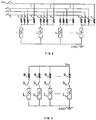
Fig. 3 is the digital luminance controlling apparatus of an embodiment of the present invention. In the figure, a group of selection switches (S1, S2, ..., SN) is connected between the resistors (R1, R2, ..., RN) and the luminaries (L1, L2, ..., LN) that compose the illuminating apparatus, and a corresponding number of luminaries can be set to the ignited state by setting different numbers of switches to the connection state, and thereby to make the light source comprising the group of luminaries provide the desired luminance in the illuminated area. Compared with the prior art technical solution as shown inFig. 2 , the embodiment could greatly reduce the number of resistors needed and the complexity of the circuits while maintaining the same luminance controlling level, thus the power consumption is reduced. -
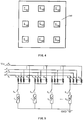
Fig. 4 is the schematic plan view of a group of luminaries composing the illuminating apparatus of an embodiment of the present invention. In the area that needs to be illuminated, there is an illuminating apparatus comprising a group of nine luminaries (L41, L42, ..., L49), and the arrangement of the luminaries is shown in the figure. It can be seen from the figure that luminaries in different positions contribute differently to the general luminous intensity of the illuminated area under the same illuminating conditions (the same rated power, the same current, etc.), for example, L45 contributes more than L44, and L44 contributes more than L41 and so on. Thus it is possible to select the least number of luminaries that are in the ignited state by using a particular algorithm according to the different contribution rates of each luminaries to the general luminous intensity of the illuminating apparatus so as to achieve the desired general luminous intensity, thus the power consumption is reduced. For instance, under the same illuminating conditions, the light source comprising L42+L44+L46+L48 could achieve the same general luminous intensity as the light source comprising L41+L43+L45+L47+L49. - Furthermore, luminaries of different rated illuminating power could be selected according to the different contribution rate of each luminary to the general luminous intensity, and resistors of different resistance values could be selected to be connected to different luminaries, thereby, different luminaries could have different luminous intensity under the same luminance controlling signal.
- In addition, some electronic devices, such as mobile phone, PDA (Personal Digital Assistant) etc., may have a display screen and a data inputting apparatus comprising a set of keys, and in the same surrounding environment, the luminous intensity of the illuminating apparatus under the control of the luminance controlling apparatus could be different in the display screen and in the area of data inputting apparatus , and thus the power consumption is further reduced.
-
Fig. 5 is a digital luminance controlling apparatus of another embodiment of the present invention, the digital luminance controlling apparatus is an improvement based on the technical solution ofFig. 3 . On the basis of the technical solution ofFig. 2 , a group of switches(SN+1, SN+2, ..., SN+M) is added between M groups of resistors (R11, R12, ..., R1N; R21, R22, ..., R2N; ...; RM1, RM2, ...RMN) and luminaries (L1, L2, ..., LM), thus compared with the technical solution ofFig. 2 , the present embodiment could have more luminance controlling levels available for selection, so that the luminance could be changed more smoothly with the change of the luminous intensity of the circumstance so as to achieve the object of reducing power consumption. -
Fig. 6 is the flow chart of the operating process of the digital luminance controlling system of an embodiment of the present invention. The display screens of electronic devices such as mobile phone, PDA (Personal Digital Assistant) have different states. In the present embodiment, there are two different types of states, i.e., the igniting state and the non-igniting state, wherein the igniting state is the working state that needs manual intervention and the non-igniting state includes the stand-by state and working state that does not need manual intervention, etc. The working state that does not need manual intervention is, for example, the state of data exchanging with the computer or network and the state of calling for a long time, etc. - The electronic devices are usually in the non-igniting state, and when the state changes to an igniting one (step S620), the luminance controlling system first detects the luminous intensity of the circumstance (step S630) and then preliminarily sets the luminous intensity of the illuminating apparatus of the system according to the luminous intensity of the circumstance (step S642) while initializing the luminous intensity of the circumstance sampling frequency (step S646). In step S642, the luminous intensity of the illuminating apparatus of the system could be set to zero according to the luminous intensity of the circumstance, i.e., not using the illuminating apparatus of the system.
- Afterward, when the next sampling time is up (step S650), it is determined whether the electronic device is in the igniting state (step S660). If it is, again the luminance controlling system detects the luminous intensity of the circumstance (step S670) and sets the luminous intensity of the illuminating apparatus of the system according to the luminous intensity of the circumstance (step S680), and if it is not in the igniting state, the whole system is set to the non-igniting state.
- When the sampling has been performed twice or more, each new sampled value of the luminous intensity of the circumstance is compared with its previous sampled value of the luminous intensity of the circumstance (step S690). If the absolute value of the difference is smaller than a certain preset value Value 1 (e.g., 2 lux), the sampling frequency of the luminous intensity of the circumstance is reduced based on the difference (step S696); if the absolute value of the difference is greater than a certain preset value Value 2 (e.g., 10 lux), the sampling frequency of the luminous intensity of the circumstance is increased based on the difference (step S692), wherein
Value 2 >Value 1; and if the absolute value of the difference is between the preset value Value1 and Value2, the sampling frequency of the luminous intensity of the circumstance remains the same(step S694). - In the end, return to step S650 according to the adjusted sampling frequency of the luminous intensity of the circumstance. When the next sampling time is up, it is determined again whether the electronic device is in the igniting state, and the above process will be repeated.
-
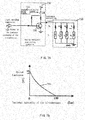
Fig. 7 is the analog luminance controlling system of an embodiment of the present invention. The analog luminance controlling system comprises alight sensing apparatus 710, an analogluminance controlling apparatus 720 and a group oflight sources 730. The analog luminance controlling apparatus further comprises amapping amplifying circuit 726, acontroller 722 with timing function and a switch 724. - When the
light sensing apparatus 710 detects the luminous intensity of the circumstance, it sends a signal of the luminous intensity of the circumstance to the analogluminance controlling apparatus 720. When the electronic device employing the analog luminance controlling system is in an igniting state, thecontroller 722 with timing function sends an activating signal to set the switch 724 to the connection state, then the signal of the luminous intensity of the circumstance is converted into luminance controlling signal according to the preset reverse magnification by the analog luminance controlling apparatus and the controlling signal is applied to the light source in the form of current or voltage to adjust the luminance of the light source. - The reverse magnification of the present embodiment is shown in the
curve 760 of the figure. The curve is continuously changed in real-time while the higher the luminous intensity of the circumstance is, the lower the luminous intensity of the system itself. The reverse magnification could be preset by the manufacturer of the electronic device or by the user. The luminance controlling system having an reverse relationship with the luminous intensity of the circumstance could be applied to electronic devices providing backlights, such as the liquid crystal display screen of the mobile phone, etc., wherein the higher the luminous intensity of the circumstance is, the lower the backlights intensity of the display screen. When the luminous intensity of the circumstance is greater than 100 lux, the backlights intensity of the display screen is zero, i.e., the illuminating apparatus of the system is not in use. - Accordingly, in the preceding digital luminance controlling system, the luminance controlling signal sent by the digital luminance controlling apparatus and the luminous intensity of the circumstance could also have a reverse relationship, and the reverse relationship could also be preset by the manufacturer of the electronic device or by the user, except that it is a non-continuous grading distribution.
- As for the analog luminance controlling system, luminaries of different rated illuminating power could be selected according to different contribution rate of each luminary to the general luminous intensity of the illuminated area. Resistors of different values could also be selected to be connected to different luminaries, and thereby different luminaries could have different luminous intensity under the same luminance controlling signal.
- In addition, some electronic devices, such as mobile phones, PDA (Personal Digital Assistant), etc., have a display screen and a data inputting apparatus comprising a set of keys. The luminous intensity of the light source under the control of the luminance controlling apparatus could be different in the display screen and in the area of data inputting apparatus while they are in the same environment, and thus the power consumption is further reduced.
-
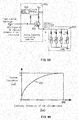
Fig. 8 is the analog luminance controlling system of another embodiment of the present invention. The system differs from the analog luminance controlling system of the embodiment inFig. 7 by that the analogluminance controlling apparatus 820 mapping amplifies the signal of the luminous intensity of the circumstance into the luminance controlling signal according to the preset positive magnification and applies it to thelight source 830 in the form of current or voltage to adjust the luminance of the light source. - The positive magnification of the present embodiment is shown as
curve 860 in the figure. The curve is continuously changed in real-time while the higher the luminous intensity of the circumstance is, the higher the luminous intensity of the system itself. The positive magnification could be preset by the manufacturer of the electronic device or by the user. The luminance controlling system having a positive relationship with the luminous intensity of the circumstance could be applied to self-illuminating electronic devices, such as traffic lights on the roads, wherein the higher the luminous intensity of the circumstance is, the higher the luminous intensity of the traffic lights so as to facilitate recognition. - Accordingly, in the preceding digital luminance controlling system, the luminance controlling signal sent by the digital luminance controlling apparatus and the luminous intensity of the circumstance could also have positive relationship, and the positive relationship could also be preset by the manufacturer of the electronic device or by the user, except that it is a non-continuous grading distribution.
-
Fig. 9 is the flow chart of the operating process of the analog luminance controlling system of an embodiment of the present invention. Electronic devices are usually in the non-igniting state, and when the state changes to an igniting one (step S920), the controller with timing function sets the switch to the connection state to set the luminance controlling apparatus to the working state (step S930). At this point, the system sends luminance controlling signal according to the detected luminous intensity of the circumstance, and the luminance controlling signal could adjust the luminous intensity of the illuminating apparatus (step S940). In step S940, the luminous intensity of the illuminating apparatus of the system could be set to zero according to the luminous intensity of the circumstance, i.e., not using the illuminating apparatus of the system. - Subsequently, the timer in the controller is set to the working state (step S950). When the timing is over, i.e., when the next detection time is up (step S962), it is determined whether the electronic device is in the igniting state (step S966). If so, return to step 950 to repeat the process until the electronic device is in the non-igniting state. If not, the controller sets the analog luminance controlling apparatus to a stand-by state (step S970) and then returns to step S910. The duration in which the timer of the controller is in the working state is preset by the manufacturer of the electronic device or by the user.
Claims (3)
- A system for controlling an illuminating apparatus, comprising:a sensing apparatus for sensing the luminous intensity of the circumstance, a luminance controlling apparatus for sending a luminance controlling signal to a light source controlling apparatus of the luminous intensity of the circumstance received from the sensing apparatus, and, a light source controlling apparatus for controlling the luminous intensity of said illuminating apparatus according to the luminance controlling signal received from the luminance controlling apparatus,characterized in that the luminance controlling apparatus is able to adjust the sampling frequency of the sampling of the luminous intensity of the circumstance according to the variation of the sensed luminous intensity of the circumstance, wherein said sampling frequency is decreased if the difference between two successive sampled luminous intensities of the circumstance is smaller than a predetermined value, and said sampling frequency is increased if the difference between two successive sampled luminous intensities of the circumstance is larger than another predetermined value.
- The system according to claim 1, wherein said luminance controlling apparatus is able to control the luminous intensity of said illuminating apparatus by adjusting the electric current passing through the luminaries.
- A method for controlling an illuminating apparatus, comprising the steps of:sensing the luminous intensity of the circumstance, generating the luminance controlling signal to the light source controlling apparatus of the luminous intensity of the circumstance, controlling the luminous intensity of said illuminating apparatus according to the luminance controlling signal, andthe method is characterized by the step of adjusting the sampling frequency of the sampling of the luminous intensity of the circumstance according to the sensed variation of the luminous intensity of the circumstance wherein said sampling frequency is decreased if the difference between two successive sampled luminous intensities of the circumstance is smaller than a predetermined value, and said sampling frequency is increased if the difference between two successive sampled luminous intensities of the circumstance is larger than another predetermined value.
Applications Claiming Priority (2)
| Application Number | Priority Date | Filing Date | Title |
|---|---|---|---|
| CNA031603513A CN1602132A (en) | 2003-09-24 | 2003-09-24 | System and method of controlling luminous device |
| PCT/IB2004/051807 WO2005029454A1 (en) | 2003-09-24 | 2004-09-21 | Method and system for controlling an illuminating apparatus |
Publications (2)
| Publication Number | Publication Date |
|---|---|
| EP1668622A1 EP1668622A1 (en) | 2006-06-14 |
| EP1668622B1 true EP1668622B1 (en) | 2017-04-26 |
Family
ID=34324123
Family Applications (1)
| Application Number | Title | Priority Date | Filing Date |
|---|---|---|---|
| EP04770043.0A Expired - Lifetime EP1668622B1 (en) | 2003-09-24 | 2004-09-21 | Method and system for controlling an illuminating apparatus |
Country Status (6)
| Country | Link |
|---|---|
| US (1) | US7714521B2 (en) |
| EP (1) | EP1668622B1 (en) |
| JP (1) | JP4663644B2 (en) |
| CN (2) | CN1602132A (en) |
| ES (1) | ES2633000T3 (en) |
| WO (1) | WO2005029454A1 (en) |
Families Citing this family (39)
| Publication number | Priority date | Publication date | Assignee | Title |
|---|---|---|---|---|
| US20050259424A1 (en) | 2004-05-18 | 2005-11-24 | Zampini Thomas L Ii | Collimating and controlling light produced by light emitting diodes |
| US7766511B2 (en) | 2006-04-24 | 2010-08-03 | Integrated Illumination Systems | LED light fixture |
| US7729941B2 (en) | 2006-11-17 | 2010-06-01 | Integrated Illumination Systems, Inc. | Apparatus and method of using lighting systems to enhance brand recognition |
| JP2008129380A (en) * | 2006-11-22 | 2008-06-05 | Sony Corp | Display device |
| US8013538B2 (en) | 2007-01-26 | 2011-09-06 | Integrated Illumination Systems, Inc. | TRI-light |
| KR101311550B1 (en) * | 2007-04-17 | 2013-09-26 | 엘지디스플레이 주식회사 | Back light unit and display device |
| US8742686B2 (en) | 2007-09-24 | 2014-06-03 | Integrated Illumination Systems, Inc. | Systems and methods for providing an OEM level networked lighting system |
| US8255487B2 (en) | 2008-05-16 | 2012-08-28 | Integrated Illumination Systems, Inc. | Systems and methods for communicating in a lighting network |
| US7972028B2 (en) * | 2008-10-31 | 2011-07-05 | Future Electronics Inc. | System, method and tool for optimizing generation of high CRI white light, and an optimized combination of light emitting diodes |
| US8585245B2 (en) | 2009-04-23 | 2013-11-19 | Integrated Illumination Systems, Inc. | Systems and methods for sealing a lighting fixture |
| KR101341021B1 (en) * | 2009-12-11 | 2013-12-13 | 엘지디스플레이 주식회사 | Apparatus and method of driving light source |
| DE102010005504A1 (en) * | 2010-01-23 | 2011-07-28 | Abb Ag, 68309 | Concealed LED light |
| US8890793B2 (en) * | 2010-03-26 | 2014-11-18 | Hong Kong Applied Science and Technology Research Institute, Co. Ltd. | Adjusting a brightness level of a backlight of a display device |
| CN103377636B (en) * | 2010-05-25 | 2015-06-17 | 友达光电股份有限公司 | How to adjust the brightness of the backlight |
| CN101859546B (en) * | 2010-05-25 | 2013-06-19 | 友达光电股份有限公司 | Method for adjusting brightness of backlight source |
| CN102679182A (en) * | 2011-03-09 | 2012-09-19 | 海洋王照明科技股份有限公司 | Lighting device |
| US9066381B2 (en) | 2011-03-16 | 2015-06-23 | Integrated Illumination Systems, Inc. | System and method for low level dimming |
| US10874003B2 (en) | 2011-07-26 | 2020-12-22 | Hunter Industries, Inc. | Systems and methods for providing power and data to devices |
| US8710770B2 (en) | 2011-07-26 | 2014-04-29 | Hunter Industries, Inc. | Systems and methods for providing power and data to lighting devices |
| US20150237700A1 (en) | 2011-07-26 | 2015-08-20 | Hunter Industries, Inc. | Systems and methods to control color and brightness of lighting devices |
| US9609720B2 (en) | 2011-07-26 | 2017-03-28 | Hunter Industries, Inc. | Systems and methods for providing power and data to lighting devices |
| US9521725B2 (en) | 2011-07-26 | 2016-12-13 | Hunter Industries, Inc. | Systems and methods for providing power and data to lighting devices |
| US11917740B2 (en) | 2011-07-26 | 2024-02-27 | Hunter Industries, Inc. | Systems and methods for providing power and data to devices |
| US8894437B2 (en) | 2012-07-19 | 2014-11-25 | Integrated Illumination Systems, Inc. | Systems and methods for connector enabling vertical removal |
| US9379578B2 (en) | 2012-11-19 | 2016-06-28 | Integrated Illumination Systems, Inc. | Systems and methods for multi-state power management |
| US9420665B2 (en) | 2012-12-28 | 2016-08-16 | Integration Illumination Systems, Inc. | Systems and methods for continuous adjustment of reference signal to control chip |
| US9485814B2 (en) | 2013-01-04 | 2016-11-01 | Integrated Illumination Systems, Inc. | Systems and methods for a hysteresis based driver using a LED as a voltage reference |
| TWI554247B (en) * | 2015-02-17 | 2016-10-21 | 正崴精密工業股份有限公司 | Vital signs measurement system and method |
| US10918030B2 (en) | 2015-05-26 | 2021-02-16 | Hunter Industries, Inc. | Decoder systems and methods for irrigation control |
| US10228711B2 (en) | 2015-05-26 | 2019-03-12 | Hunter Industries, Inc. | Decoder systems and methods for irrigation control |
| US10060599B2 (en) | 2015-05-29 | 2018-08-28 | Integrated Illumination Systems, Inc. | Systems, methods and apparatus for programmable light fixtures |
| US10030844B2 (en) | 2015-05-29 | 2018-07-24 | Integrated Illumination Systems, Inc. | Systems, methods and apparatus for illumination using asymmetrical optics |
| CN105405429B (en) * | 2015-12-11 | 2019-03-26 | Tcl移动通信科技(宁波)有限公司 | A mobile terminal and its ambient light dynamic sensing control method and system |
| CN105702230B (en) * | 2016-04-14 | 2018-06-05 | 广东欧珀移动通信有限公司 | Display backlight luminance regulating method, device and the terminal of a kind of terminal |
| CN109243383B (en) * | 2018-11-09 | 2021-12-17 | 珠海格力电器股份有限公司 | Backlight brightness adjusting method of display screen and display screen device |
| US10801714B1 (en) | 2019-10-03 | 2020-10-13 | CarJamz, Inc. | Lighting device |
| CN112383991A (en) * | 2020-11-20 | 2021-02-19 | 山东信达物联应用技术有限公司 | Street lamp control method and system |
| US12416908B2 (en) | 2022-12-29 | 2025-09-16 | Integrated Illumination Systems, Inc. | Systems and methods for manufacturing light fixtures |
| US12297996B2 (en) | 2023-02-16 | 2025-05-13 | Integrated Illumination Systems, Inc. | Cove light fixture with hidden integrated air return |
Family Cites Families (19)
| Publication number | Priority date | Publication date | Assignee | Title |
|---|---|---|---|---|
| GB9125331D0 (en) * | 1991-11-28 | 1992-01-29 | Shaye Communications Ltd | Illumination of displays |
| JP2752309B2 (en) * | 1993-01-19 | 1998-05-18 | 松下電器産業株式会社 | Display device |
| JPH09504902A (en) * | 1993-11-03 | 1997-05-13 | サイエンス アプリケーションズ インターナショナル コーポレイション | High efficiency UV backlight system for backlighting of electronic display devices |
| US5554912A (en) * | 1995-05-15 | 1996-09-10 | Delco Electronics Corporation | Adaptive instrument display brightness control system |
| US5760760A (en) | 1995-07-17 | 1998-06-02 | Dell Usa, L.P. | Intelligent LCD brightness control system |
| US6271813B1 (en) * | 1996-08-30 | 2001-08-07 | Lear Automotive Dearborn, Inc. | Voltage control for adjusting the brightness of a screen display |
| JPH11233269A (en) * | 1998-02-13 | 1999-08-27 | Matsushita Electric Works Ltd | Lighting system |
| JP4169135B2 (en) * | 1998-03-25 | 2008-10-22 | ハリソン東芝ライティング株式会社 | Lamp lighting device |
| EP1006506A1 (en) * | 1998-12-03 | 2000-06-07 | Hewlett-Packard Company | Optical vehicle display |
| WO2000041378A1 (en) | 1998-12-31 | 2000-07-13 | Nokia Mobile Phones Limited | Backlight for a portable device |
| US20020109664A1 (en) * | 1999-02-19 | 2002-08-15 | Masaki Shimada | Display apparatus and an image processing apparatus |
| FR2802692B1 (en) * | 1999-12-17 | 2003-05-16 | Thomson Csf Sextant | LIGHTING DEVICE FOR A LIQUID CRYSTAL SCREEN |
| JP4024444B2 (en) * | 1999-12-27 | 2007-12-19 | 株式会社東芝 | Wireless telephone equipment |
| TWI252592B (en) * | 2000-01-17 | 2006-04-01 | Semiconductor Energy Lab | EL display device |
| JP3438693B2 (en) * | 2000-02-03 | 2003-08-18 | 日本電気株式会社 | Electronic device with display |
| EP1227642A1 (en) | 2001-01-26 | 2002-07-31 | Telefonaktiebolaget L M Ericsson (Publ) | Back light device for a hand-held electronic device |
| US20020196854A1 (en) | 2001-06-15 | 2002-12-26 | Jongil Kim | Fast video encoder using adaptive hierarchical video processing in a down-sampled domain |
| US20020196954A1 (en) * | 2001-06-22 | 2002-12-26 | Marxen Christopher J. | Modeling and fabrication of three-dimensional irregular surfaces for hearing instruments |
| KR100422799B1 (en) * | 2001-12-13 | 2004-03-16 | 주식회사 팬택앤큐리텔 | Method of Dynamically lightening Back-lights of Mobile Phone |
-
2003
- 2003-09-24 CN CNA031603513A patent/CN1602132A/en active Pending
-
2004
- 2004-09-21 ES ES04770043.0T patent/ES2633000T3/en not_active Expired - Lifetime
- 2004-09-21 EP EP04770043.0A patent/EP1668622B1/en not_active Expired - Lifetime
- 2004-09-21 US US10/572,846 patent/US7714521B2/en active Active
- 2004-09-21 WO PCT/IB2004/051807 patent/WO2005029454A1/en not_active Ceased
- 2004-09-21 CN CNB2004800278026A patent/CN100483485C/en not_active Expired - Lifetime
- 2004-09-21 JP JP2006527545A patent/JP4663644B2/en not_active Expired - Lifetime
Non-Patent Citations (1)
| Title |
|---|
| None * |
Also Published As
| Publication number | Publication date |
|---|---|
| EP1668622A1 (en) | 2006-06-14 |
| US7714521B2 (en) | 2010-05-11 |
| WO2005029454A1 (en) | 2005-03-31 |
| JP2007507069A (en) | 2007-03-22 |
| CN1856815A (en) | 2006-11-01 |
| JP4663644B2 (en) | 2011-04-06 |
| CN1602132A (en) | 2005-03-30 |
| ES2633000T3 (en) | 2017-09-18 |
| US20060291199A1 (en) | 2006-12-28 |
| WO2005029454B1 (en) | 2005-05-26 |
| CN100483485C (en) | 2009-04-29 |
Similar Documents
| Publication | Publication Date | Title |
|---|---|---|
| US7714521B2 (en) | Methods and system for controlling an illuminating apparatus | |
| CN101188098B (en) | display drive circuit | |
| US6762741B2 (en) | Automatic brightness control system and method for a display device using a logarithmic sensor | |
| US8797269B2 (en) | Automatic keypad backlight adjustment on a mobile handheld electronic device | |
| JP4397097B2 (en) | Plasma display device | |
| JP2001215914A (en) | Electronic equipment with display part | |
| KR20050040296A (en) | Display apparatus and control method thereof | |
| KR100381423B1 (en) | portable computer and controlling method thereof | |
| CN112600955B (en) | Electrical device with a touch screen and a user interface for adjusting screen brightness | |
| CN100433101C (en) | Device and method for driving organic electroluminescence display | |
| EP2224696B1 (en) | Automatic keypad backlight adjustment on a mobile handheld electronic device | |
| JP4588936B2 (en) | Liquid crystal display device and automatic dimming control method thereof | |
| JP2000324238A (en) | Lighting device for mobile radio unit | |
| GB2391752A (en) | Reducing power consumption of display illumination | |
| JP2006146030A (en) | Electronic device and its control method | |
| JP2000112421A (en) | Light quantity control method for light-emitting part and telephone having light-emitting part controlling light quantity | |
| EP1754023A2 (en) | Light display for a video game device | |
| KR200241335Y1 (en) | Apparatus for Adjusting Brightness of Electric Light Signboard | |
| KR100453893B1 (en) | Apparatus to control driving power automatically for plasma display panel and the method thereof | |
| JP2001155892A (en) | Light adjustment apparatus | |
| JP2000214434A (en) | LCD backlight display device | |
| JP3492608B2 (en) | Mobile phone equipment | |
| JPH0536487A (en) | Fluorescent tube lighting device | |
| KR20050117174A (en) | Luminosity auto-control apparatus of the display part by using camera of the portable phone | |
| KR20030005966A (en) | computer system and displaying method of video signal thereof |
Legal Events
| Date | Code | Title | Description |
|---|---|---|---|
| PUAI | Public reference made under article 153(3) epc to a published international application that has entered the european phase |
Free format text: ORIGINAL CODE: 0009012 |
|
| 17P | Request for examination filed |
Effective date: 20060424 |
|
| AK | Designated contracting states |
Kind code of ref document: A1 Designated state(s): AT BE BG CH CY CZ DE DK EE ES FI FR GB GR HU IE IT LI LU MC NL PL PT RO SE SI SK TR |
|
| DAX | Request for extension of the european patent (deleted) | ||
| 17Q | First examination report despatched |
Effective date: 20081210 |
|
| RAP1 | Party data changed (applicant data changed or rights of an application transferred) |
Owner name: KONINKLIJKE PHILIPS N.V. |
|
| RAP1 | Party data changed (applicant data changed or rights of an application transferred) |
Owner name: PHILIPS LIGHTING HOLDING B.V. |
|
| GRAP | Despatch of communication of intention to grant a patent |
Free format text: ORIGINAL CODE: EPIDOSNIGR1 |
|
| INTG | Intention to grant announced |
Effective date: 20161128 |
|
| GRAS | Grant fee paid |
Free format text: ORIGINAL CODE: EPIDOSNIGR3 |
|
| GRAA | (expected) grant |
Free format text: ORIGINAL CODE: 0009210 |
|
| AK | Designated contracting states |
Kind code of ref document: B1 Designated state(s): AT BE BG CH CY CZ DE DK EE ES FI FR GB GR HU IE IT LI LU MC NL PL PT RO SE SI SK TR |
|
| REG | Reference to a national code |
Ref country code: GB Ref legal event code: FG4D |
|
| REG | Reference to a national code |
Ref country code: CH Ref legal event code: EP Ref country code: DE Ref legal event code: R081 Ref document number: 602004051160 Country of ref document: DE Owner name: SIGNIFY HOLDING B.V., NL Free format text: FORMER OWNER: KONINKLIJKE PHILIPS ELECTRONICS N.V., EINDHOVEN, NL |
|
| REG | Reference to a national code |
Ref country code: AT Ref legal event code: REF Ref document number: 888487 Country of ref document: AT Kind code of ref document: T Effective date: 20170515 |
|
| REG | Reference to a national code |
Ref country code: IE Ref legal event code: FG4D |
|
| REG | Reference to a national code |
Ref country code: DE Ref legal event code: R096 Ref document number: 602004051160 Country of ref document: DE |
|
| REG | Reference to a national code |
Ref country code: NL Ref legal event code: MP Effective date: 20170426 |
|
| REG | Reference to a national code |
Ref country code: AT Ref legal event code: MK05 Ref document number: 888487 Country of ref document: AT Kind code of ref document: T Effective date: 20170426 |
|
| REG | Reference to a national code |
Ref country code: ES Ref legal event code: FG2A Ref document number: 2633000 Country of ref document: ES Kind code of ref document: T3 Effective date: 20170918 |
|
| REG | Reference to a national code |
Ref country code: FR Ref legal event code: PLFP Year of fee payment: 14 |
|
| PG25 | Lapsed in a contracting state [announced via postgrant information from national office to epo] |
Ref country code: NL Free format text: LAPSE BECAUSE OF FAILURE TO SUBMIT A TRANSLATION OF THE DESCRIPTION OR TO PAY THE FEE WITHIN THE PRESCRIBED TIME-LIMIT Effective date: 20170426 |
|
| PG25 | Lapsed in a contracting state [announced via postgrant information from national office to epo] |
Ref country code: FI Free format text: LAPSE BECAUSE OF FAILURE TO SUBMIT A TRANSLATION OF THE DESCRIPTION OR TO PAY THE FEE WITHIN THE PRESCRIBED TIME-LIMIT Effective date: 20170426 Ref country code: AT Free format text: LAPSE BECAUSE OF FAILURE TO SUBMIT A TRANSLATION OF THE DESCRIPTION OR TO PAY THE FEE WITHIN THE PRESCRIBED TIME-LIMIT Effective date: 20170426 Ref country code: GR Free format text: LAPSE BECAUSE OF FAILURE TO SUBMIT A TRANSLATION OF THE DESCRIPTION OR TO PAY THE FEE WITHIN THE PRESCRIBED TIME-LIMIT Effective date: 20170727 |
|
| PG25 | Lapsed in a contracting state [announced via postgrant information from national office to epo] |
Ref country code: PL Free format text: LAPSE BECAUSE OF FAILURE TO SUBMIT A TRANSLATION OF THE DESCRIPTION OR TO PAY THE FEE WITHIN THE PRESCRIBED TIME-LIMIT Effective date: 20170426 Ref country code: BG Free format text: LAPSE BECAUSE OF FAILURE TO SUBMIT A TRANSLATION OF THE DESCRIPTION OR TO PAY THE FEE WITHIN THE PRESCRIBED TIME-LIMIT Effective date: 20170726 Ref country code: SE Free format text: LAPSE BECAUSE OF FAILURE TO SUBMIT A TRANSLATION OF THE DESCRIPTION OR TO PAY THE FEE WITHIN THE PRESCRIBED TIME-LIMIT Effective date: 20170426 |
|
| REG | Reference to a national code |
Ref country code: DE Ref legal event code: R097 Ref document number: 602004051160 Country of ref document: DE |
|
| PG25 | Lapsed in a contracting state [announced via postgrant information from national office to epo] |
Ref country code: RO Free format text: LAPSE BECAUSE OF FAILURE TO SUBMIT A TRANSLATION OF THE DESCRIPTION OR TO PAY THE FEE WITHIN THE PRESCRIBED TIME-LIMIT Effective date: 20170426 Ref country code: EE Free format text: LAPSE BECAUSE OF FAILURE TO SUBMIT A TRANSLATION OF THE DESCRIPTION OR TO PAY THE FEE WITHIN THE PRESCRIBED TIME-LIMIT Effective date: 20170426 Ref country code: SK Free format text: LAPSE BECAUSE OF FAILURE TO SUBMIT A TRANSLATION OF THE DESCRIPTION OR TO PAY THE FEE WITHIN THE PRESCRIBED TIME-LIMIT Effective date: 20170426 Ref country code: CZ Free format text: LAPSE BECAUSE OF FAILURE TO SUBMIT A TRANSLATION OF THE DESCRIPTION OR TO PAY THE FEE WITHIN THE PRESCRIBED TIME-LIMIT Effective date: 20170426 Ref country code: DK Free format text: LAPSE BECAUSE OF FAILURE TO SUBMIT A TRANSLATION OF THE DESCRIPTION OR TO PAY THE FEE WITHIN THE PRESCRIBED TIME-LIMIT Effective date: 20170426 |
|
| PLBE | No opposition filed within time limit |
Free format text: ORIGINAL CODE: 0009261 |
|
| STAA | Information on the status of an ep patent application or granted ep patent |
Free format text: STATUS: NO OPPOSITION FILED WITHIN TIME LIMIT |
|
| 26N | No opposition filed |
Effective date: 20180129 |
|
| REG | Reference to a national code |
Ref country code: CH Ref legal event code: PL |
|
| PG25 | Lapsed in a contracting state [announced via postgrant information from national office to epo] |
Ref country code: SI Free format text: LAPSE BECAUSE OF FAILURE TO SUBMIT A TRANSLATION OF THE DESCRIPTION OR TO PAY THE FEE WITHIN THE PRESCRIBED TIME-LIMIT Effective date: 20170426 Ref country code: MC Free format text: LAPSE BECAUSE OF FAILURE TO SUBMIT A TRANSLATION OF THE DESCRIPTION OR TO PAY THE FEE WITHIN THE PRESCRIBED TIME-LIMIT Effective date: 20170426 |
|
| REG | Reference to a national code |
Ref country code: IE Ref legal event code: MM4A |
|
| REG | Reference to a national code |
Ref country code: BE Ref legal event code: MM Effective date: 20170930 |
|
| PG25 | Lapsed in a contracting state [announced via postgrant information from national office to epo] |
Ref country code: LU Free format text: LAPSE BECAUSE OF NON-PAYMENT OF DUE FEES Effective date: 20170921 |
|
| PG25 | Lapsed in a contracting state [announced via postgrant information from national office to epo] |
Ref country code: CH Free format text: LAPSE BECAUSE OF NON-PAYMENT OF DUE FEES Effective date: 20170930 Ref country code: LI Free format text: LAPSE BECAUSE OF NON-PAYMENT OF DUE FEES Effective date: 20170930 Ref country code: IE Free format text: LAPSE BECAUSE OF NON-PAYMENT OF DUE FEES Effective date: 20170921 |
|
| PG25 | Lapsed in a contracting state [announced via postgrant information from national office to epo] |
Ref country code: BE Free format text: LAPSE BECAUSE OF NON-PAYMENT OF DUE FEES Effective date: 20170930 |
|
| REG | Reference to a national code |
Ref country code: FR Ref legal event code: PLFP Year of fee payment: 15 |
|
| PG25 | Lapsed in a contracting state [announced via postgrant information from national office to epo] |
Ref country code: HU Free format text: LAPSE BECAUSE OF FAILURE TO SUBMIT A TRANSLATION OF THE DESCRIPTION OR TO PAY THE FEE WITHIN THE PRESCRIBED TIME-LIMIT; INVALID AB INITIO Effective date: 20040921 |
|
| PG25 | Lapsed in a contracting state [announced via postgrant information from national office to epo] |
Ref country code: CY Free format text: LAPSE BECAUSE OF NON-PAYMENT OF DUE FEES Effective date: 20170426 |
|
| PG25 | Lapsed in a contracting state [announced via postgrant information from national office to epo] |
Ref country code: TR Free format text: LAPSE BECAUSE OF FAILURE TO SUBMIT A TRANSLATION OF THE DESCRIPTION OR TO PAY THE FEE WITHIN THE PRESCRIBED TIME-LIMIT Effective date: 20170426 |
|
| PG25 | Lapsed in a contracting state [announced via postgrant information from national office to epo] |
Ref country code: PT Free format text: LAPSE BECAUSE OF FAILURE TO SUBMIT A TRANSLATION OF THE DESCRIPTION OR TO PAY THE FEE WITHIN THE PRESCRIBED TIME-LIMIT Effective date: 20170426 |
|
| REG | Reference to a national code |
Ref country code: DE Ref legal event code: R082 Ref document number: 602004051160 Country of ref document: DE Representative=s name: MEISSNER BOLTE PATENTANWAELTE RECHTSANWAELTE P, DE Ref country code: DE Ref legal event code: R081 Ref document number: 602004051160 Country of ref document: DE Owner name: SIGNIFY HOLDING B.V., NL Free format text: FORMER OWNER: PHILIPS LIGHTING HOLDING B.V., EINDHOVEN, NL |
|
| P01 | Opt-out of the competence of the unified patent court (upc) registered |
Effective date: 20230421 |
|
| PGFP | Annual fee paid to national office [announced via postgrant information from national office to epo] |
Ref country code: IT Payment date: 20230920 Year of fee payment: 20 Ref country code: GB Payment date: 20230926 Year of fee payment: 20 |
|
| PGFP | Annual fee paid to national office [announced via postgrant information from national office to epo] |
Ref country code: FR Payment date: 20230926 Year of fee payment: 20 |
|
| PGFP | Annual fee paid to national office [announced via postgrant information from national office to epo] |
Ref country code: ES Payment date: 20231017 Year of fee payment: 20 |
|
| PGFP | Annual fee paid to national office [announced via postgrant information from national office to epo] |
Ref country code: DE Payment date: 20231127 Year of fee payment: 20 |
|
| REG | Reference to a national code |
Ref country code: DE Ref legal event code: R071 Ref document number: 602004051160 Country of ref document: DE |
|
| PG25 | Lapsed in a contracting state [announced via postgrant information from national office to epo] |
Ref country code: GB Free format text: LAPSE BECAUSE OF EXPIRATION OF PROTECTION Effective date: 20240920 |
|
| REG | Reference to a national code |
Ref country code: GB Ref legal event code: PE20 Expiry date: 20240920 |
|
| PG25 | Lapsed in a contracting state [announced via postgrant information from national office to epo] |
Ref country code: GB Free format text: LAPSE BECAUSE OF EXPIRATION OF PROTECTION Effective date: 20240920 |
|
| REG | Reference to a national code |
Ref country code: ES Ref legal event code: FD2A Effective date: 20241205 |
|
| PG25 | Lapsed in a contracting state [announced via postgrant information from national office to epo] |
Ref country code: ES Free format text: LAPSE BECAUSE OF EXPIRATION OF PROTECTION Effective date: 20240922 |
|
| PG25 | Lapsed in a contracting state [announced via postgrant information from national office to epo] |
Ref country code: ES Free format text: LAPSE BECAUSE OF EXPIRATION OF PROTECTION Effective date: 20240922 |