EP1668216B1 - A child safety barrier with a locking device - Google Patents
A child safety barrier with a locking device Download PDFInfo
- Publication number
- EP1668216B1 EP1668216B1 EP20040762821 EP04762821A EP1668216B1 EP 1668216 B1 EP1668216 B1 EP 1668216B1 EP 20040762821 EP20040762821 EP 20040762821 EP 04762821 A EP04762821 A EP 04762821A EP 1668216 B1 EP1668216 B1 EP 1668216B1
- Authority
- EP
- European Patent Office
- Prior art keywords
- door
- safety barrier
- child safety
- locking
- push
- Prior art date
- Legal status (The legal status is an assumption and is not a legal conclusion. Google has not performed a legal analysis and makes no representation as to the accuracy of the status listed.)
- Expired - Lifetime
Links
- 230000004888 barrier function Effects 0.000 title claims abstract description 35
- 230000004913 activation Effects 0.000 claims abstract description 16
- 238000004137 mechanical activation Methods 0.000 abstract 1
- 239000004033 plastic Substances 0.000 description 3
- 229920003023 plastic Polymers 0.000 description 3
- 210000002414 leg Anatomy 0.000 description 2
- 229910000831 Steel Inorganic materials 0.000 description 1
- 238000013459 approach Methods 0.000 description 1
- 230000000903 blocking effect Effects 0.000 description 1
- 238000006073 displacement reaction Methods 0.000 description 1
- 210000003127 knee Anatomy 0.000 description 1
- 239000010959 steel Substances 0.000 description 1
- 239000002023 wood Substances 0.000 description 1
Images


Classifications
-
- E—FIXED CONSTRUCTIONS
- E05—LOCKS; KEYS; WINDOW OR DOOR FITTINGS; SAFES
- E05B—LOCKS; ACCESSORIES THEREFOR; HANDCUFFS
- E05B47/00—Operating or controlling locks or other fastening devices by electric or magnetic means
- E05B47/0046—Electric or magnetic means in the striker or on the frame; Operating or controlling the striker plate
-
- E—FIXED CONSTRUCTIONS
- E05—LOCKS; KEYS; WINDOW OR DOOR FITTINGS; SAFES
- E05B—LOCKS; ACCESSORIES THEREFOR; HANDCUFFS
- E05B47/00—Operating or controlling locks or other fastening devices by electric or magnetic means
- E05B47/02—Movement of the bolt by electromagnetic means; Adaptation of locks, latches, or parts thereof, for movement of the bolt by electromagnetic means
- E05B47/026—Movement of the bolt by electromagnetic means; Adaptation of locks, latches, or parts thereof, for movement of the bolt by electromagnetic means the bolt moving rectilinearly
-
- E—FIXED CONSTRUCTIONS
- E05—LOCKS; KEYS; WINDOW OR DOOR FITTINGS; SAFES
- E05B—LOCKS; ACCESSORIES THEREFOR; HANDCUFFS
- E05B65/00—Locks or fastenings for special use
- E05B65/0014—Locks or fastenings for special use to prevent opening by children
-
- E—FIXED CONSTRUCTIONS
- E05—LOCKS; KEYS; WINDOW OR DOOR FITTINGS; SAFES
- E05C—BOLTS OR FASTENING DEVICES FOR WINGS, SPECIALLY FOR DOORS OR WINDOWS
- E05C19/00—Other devices specially designed for securing wings, e.g. with suction cups
- E05C19/16—Devices holding the wing by magnetic or electromagnetic attraction
- E05C19/163—Devices holding the wing by magnetic or electromagnetic attraction a movable bolt being held in the striker by a permanent magnet
-
- E—FIXED CONSTRUCTIONS
- E06—DOORS, WINDOWS, SHUTTERS, OR ROLLER BLINDS IN GENERAL; LADDERS
- E06B—FIXED OR MOVABLE CLOSURES FOR OPENINGS IN BUILDINGS, VEHICLES, FENCES OR LIKE ENCLOSURES IN GENERAL, e.g. DOORS, WINDOWS, BLINDS, GATES
- E06B9/00—Screening or protective devices for wall or similar openings, with or without operating or securing mechanisms; Closures of similar construction
- E06B9/02—Shutters, movable grilles, or other safety closing devices, e.g. against burglary
- E06B9/04—Shutters, movable grilles, or other safety closing devices, e.g. against burglary of wing type, e.g. revolving or sliding
-
- E—FIXED CONSTRUCTIONS
- E05—LOCKS; KEYS; WINDOW OR DOOR FITTINGS; SAFES
- E05B—LOCKS; ACCESSORIES THEREFOR; HANDCUFFS
- E05B47/00—Operating or controlling locks or other fastening devices by electric or magnetic means
- E05B47/0001—Operating or controlling locks or other fastening devices by electric or magnetic means with electric actuators; Constructional features thereof
- E05B47/0002—Operating or controlling locks or other fastening devices by electric or magnetic means with electric actuators; Constructional features thereof with electromagnets
-
- E—FIXED CONSTRUCTIONS
- E05—LOCKS; KEYS; WINDOW OR DOOR FITTINGS; SAFES
- E05C—BOLTS OR FASTENING DEVICES FOR WINGS, SPECIALLY FOR DOORS OR WINDOWS
- E05C19/00—Other devices specially designed for securing wings, e.g. with suction cups
- E05C19/006—Other devices specially designed for securing wings, e.g. with suction cups by displacement of the wing substantially in its own plane
-
- E—FIXED CONSTRUCTIONS
- E06—DOORS, WINDOWS, SHUTTERS, OR ROLLER BLINDS IN GENERAL; LADDERS
- E06B—FIXED OR MOVABLE CLOSURES FOR OPENINGS IN BUILDINGS, VEHICLES, FENCES OR LIKE ENCLOSURES IN GENERAL, e.g. DOORS, WINDOWS, BLINDS, GATES
- E06B9/00—Screening or protective devices for wall or similar openings, with or without operating or securing mechanisms; Closures of similar construction
- E06B2009/002—Safety guards or gates
-
- Y—GENERAL TAGGING OF NEW TECHNOLOGICAL DEVELOPMENTS; GENERAL TAGGING OF CROSS-SECTIONAL TECHNOLOGIES SPANNING OVER SEVERAL SECTIONS OF THE IPC; TECHNICAL SUBJECTS COVERED BY FORMER USPC CROSS-REFERENCE ART COLLECTIONS [XRACs] AND DIGESTS
- Y10—TECHNICAL SUBJECTS COVERED BY FORMER USPC
- Y10T—TECHNICAL SUBJECTS COVERED BY FORMER US CLASSIFICATION
- Y10T292/00—Closure fasteners
- Y10T292/11—Magnetic
-
- Y—GENERAL TAGGING OF NEW TECHNOLOGICAL DEVELOPMENTS; GENERAL TAGGING OF CROSS-SECTIONAL TECHNOLOGIES SPANNING OVER SEVERAL SECTIONS OF THE IPC; TECHNICAL SUBJECTS COVERED BY FORMER USPC CROSS-REFERENCE ART COLLECTIONS [XRACs] AND DIGESTS
- Y10—TECHNICAL SUBJECTS COVERED BY FORMER USPC
- Y10T—TECHNICAL SUBJECTS COVERED BY FORMER US CLASSIFICATION
- Y10T70/00—Locks
- Y10T70/50—Special application
- Y10T70/5889—For automotive vehicles
- Y10T70/5973—Remote control
- Y10T70/5978—With switch
Definitions
- the invention relates to a child safety barrier with a door which has a locking device.
- Such child safety barriers which are used for blocking openings to stairs, windows, doors and the like, are available in many versions. Most of them are composed of tubular steel, wood or plastics and have means allowing them to be mounted in openings of different widths by means of a special bracket.
- Typical basic structures of these child safety barriers may be as follows:
- the above-mentioned types of doors are frequently provided with a U-shaped lattice frame to which a door is hinged between two columns in the U-shaped frame, said door being provided with locking means to ensure that small children cannot open the door.
- GB Patent No. 1,089,798 discloses a safety door which, by means of magnets, is protected against the possibility that a child can push the door upwards, and, thus, it cannot be opened by the child. According to the GB document, it is not so that the magnets are involved in the actual locking of the door, but are involved in protecting the locking device against being opened and in ensuring that the door does not bounce back if it is slammed.
- the document DE 101 46 525 A discloses a child safety barrier according to the preamble of claim 1 and including an activation device comprising a solenoid operable by a push-button.
- the object of the invention is to provide an alternative child safety barrier, where it is not necessary to use hands and/or feet/legs.
- a child safety barrier of the type defined in the introductory portion of claim 1 which is characterized in that that the door is fixed in a U-shaped frame between two columns, where one column accommodates a slidable column on which a locking housing is mounted through a groove in the one column, while a horizontal, slidable locking pawl is mounted in an outer post of the door , said locking pawl being movable between a first position and a second position in and out of a groove in the locking housing, and that a magnet is arranged at the bottom of the locking housing, and that an inclined slide face is arranged inside the locking housing, said first position corresponds to that the door is closed, said second position corresponds to the door is opened, after the pawl is moved along the slideable face out of the groove.
- the activation device is connected with one end of a push/pull rod, while the opposite end of the push/pull rod is connected with the slidable column, and, as stated in claim 3, the push/pull rod, over part of its length, is moved through holes in a housing having upper and lower surfaces, said holes being arranged in the upper and lower surfaces, and a spring is mounted inside the housing whose one end abuts one of the surfaces, while the opposite end of the spring is secured to the push/pull rod so that the push/pull rod is affected by the force provided by the spring, thereby providing a stable mechanical structure of the locking device with stable states in the open as well as the closed state of the door.
- an easy way of operating the locking device is that the activation device is formed by a relay.
- the signal generator is formed by a push-button, or, and as stated in claim 6, that the push-button is disposed close to the door, but inaccessible to children, or, as stated in claim 7, that the signal generator is formed by an electric voltage, or, as stated in claim 8, that the signal generator is formed by a transmitter which causes a receiver to release the locking device so that the door may be opened, or, as stated in claim 9, that the signal generator is provided wirelessly from a remote control using a connection of the type IR, Bluetooth or the like.
- the door can be opened only after a certain time delay, e.g. of 2 - 4 seconds, after the activation device has received a signal from the signal generator, it is ensured that an adult can reach the door before it physically can be opened.
- a certain time delay e.g. of 2 - 4 seconds
- the door may be caused to assume a position where it is closed only after a user has physically affected the door, thereby avoiding the situation that a door seemingly closed is ajar in reality.
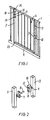
- Fig. 1 shows a child safety barrier, not forming part of the invention, but representing background art that is useful for understanding the invention, which consists of a U-shaped outer frame 1 and a door 4, shown here as a lattice, hinged to the frame.
- a locking housing 10 is fixed to a vertical post 13 of the U-shaped frame 13, while a locking pawl 8 is mounted adjoining the locking housing 10 and is secured to a vertical post 7 of the door 4.
- Figs. 2 and 3 are more detailed views of the parts which are incorporated in the magnetic locking device.
- the door Normally, the door will swing to its closed position when a spring (not shown) or a cam disc affects the door to its closed position.
- the locking pawl 8 When the door is swung to the closed position, the locking pawl 8 will be pulled toward a magnet 9 disposed inside at the bottom of the locking housing 10, said locking pawl entering into a groove 11 in the locking housing 10, whereby the door 4 will be locked to the U-shaped frame 1.
- the locking housing 10 is formed with an inclined face 12 on which the locking pawl 8 may slide, cf. the following.
- Fig. 4 shows the upper and lower hinge parts of the door which are formed by an upper hinge pin 17 which is secured to the door 4 with two plastics sleeves 18, 19.
- the pin 17 may rotate freely relative to a hinge pin bushing 21. Further, the hinge pin 17 and the entire door 4 may be displaced in a vertical direction.
- the lower hinge parts of the door may be formed by a hinge pin bushing 23, which is connected with the door 4 and may rotate relative to a hinge pin 22 securely fixed to a lower transverse rail 6 of the U-shaped frame.
- the door may thus be lifted vertically, as the hinge pin 17 may be moved between the plastics sleeves 18, 19, while the hinge pin bushing may be moved relative to the hinge pin 22.
- a spring 26 is mounted on the lower hinge pin 22 and is secured and fixed against a support ring 27 which is secured in a vertical post 2 of the door 4.
- Figs 5 and 6 show an example of a child safety barrier not forming part of the invention, but representing background art that is useful for understanding the invention.
- the numeral 42 designates a two-part handle which surrounds a moulded trigger 38, a lock 33, a locking pawl 29 and a locking bushing 28. These parts are secured to the top of the door 4. As will be seen, the lock can rotate about its pivot point 37.
- a magnet housing 31 is secured to the vertical post 2.
- the magnet housing 31 has an oblong, vertical locking groove 32.
- the locking pawl 29 is attracted by a magnetic force from a magnet 30 disposed at the bottom of the locking groove 32 so that the locking pawl is moved horizontally into the locking groove 32.
- the locking pawl is connected at its one end with a lock 33 having an inclined engagement face 36 on which a face on one end of the trigger 38 may rest.
- the trigger is rotatably connected with the handle 42 about a pivot point 40. Further, the trigger is biased with a spring 41 so that the end of the trigger 38 opposite the pivot point is pressed against the inclined face 36 on the lock 33.
- an upwardly directed force is applied from the handle to the trigger 38, whereby the trigger rotates about its pivot point 40, while the lock 33 rotates about a pivot point 37, which means that the locking pin is displaced from the magnet 30 in the locking groove 32. If the force on the lock 33 is maintained, the door may be opened.
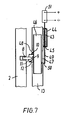
- Fig. 7 shows an embodiment of the magnetic locking device of a child safety barrier according to the invention.
- Fig. 7 also shows the vertical post 2 of the door 4 with the locking pawl 8 which is capable of engaging the groove 11 in the locking housing 10, which contains the magnet 9 and the inclined face 12, which, however, is shown here at the bottom of the locking housing 10, which is mounted on a column 46, movable relative to the column 13 of the U-shaped frame, through a groove 48 in the column 13.
- a push/pull rod 49 is mounted at an attachment point 50 on the movable column 46.
- the push/pull rod is spring-biased in a housing 44 by a spring 43 which causes the column to assume the position shown in the figure.
- the spring is secured to the push/pull rod at its one end, for example, but not necessarily, with a small plate shown at 45 capable of engaging the bottom of the housing 44, while the opposite end of the spring engages the upper part of the housing 44.
- the free end of the push/pull rod is connected with an actuator 51, e.g. a coil actuator, in a housing which is immovably secured to e.g. the column 13 of the U-shaped frame.
- an actuator 51 e.g. a coil actuator
Landscapes
- Engineering & Computer Science (AREA)
- Physics & Mathematics (AREA)
- Electromagnetism (AREA)
- Structural Engineering (AREA)
- Mechanical Engineering (AREA)
- Architecture (AREA)
- Civil Engineering (AREA)
- Lock And Its Accessories (AREA)
- Adornments (AREA)
Abstract
Description
- The invention relates to a child safety barrier with a door which has a locking device. Such child safety barriers, which are used for blocking openings to stairs, windows, doors and the like, are available in many versions. Most of them are composed of tubular steel, wood or plastics and have means allowing them to be mounted in openings of different widths by means of a special bracket.
- It is common to these child safety barriers that they are provided with a locking device which cannot be operated by children, who are thus prevented from opening the door, with the resulting fatal consequences this may have.
- Typical basic structures of these child safety barriers may be as follows:
- a) There are purely spring-loaded doors where a vertical, upwardly directed lift can lift the door out of its bracket.
- b) "Push and lift" devices where two simultaneous movements are to be performed to release the locking device of the door.
- c) Activation of a foot pedal down against a floor to make it possible to push the door by a knee.
- The above-mentioned types of doors are frequently provided with a U-shaped lattice frame to which a door is hinged between two columns in the U-shaped frame, said door being provided with locking means to ensure that small children cannot open the door.
- As for examples of child safety barriers with locking devices which cannot be operated by children, reference may be made to
WO 97/40253 US Patent 5,396,732 .
The above-mentioned locking devices are activated in that hands and/or feet/legs are to activate the locking device when a passageway is to be established. If, e.g., a parent has a child on his/hers arm, only one arm will be free, which may make it difficult and in some cases impossible to activate the locking device. - If, additionally, the parent leans against the door with the child on his/hers arm in order to activate the locking device, dangerous situations may arise, if the door is placed, in front of stairs, as the pressure on the door may mean that both the child and the parent risk falling down the stairs when the door is opened.
-
GB Patent No. 1,089,798 - The document
DE 101 46 525 A discloses a child safety barrier according to the preamble of claim 1 and including an activation device comprising a solenoid operable by a push-button. - Accordingly, the object of the invention is to provide an alternative child safety barrier, where it is not necessary to use hands and/or feet/legs.
- The object of the invention is achieved by a child safety barrier of the type defined in the introductory portion of claim 1, which is characterized in that that the door is fixed in a U-shaped frame between two columns, where one column accommodates a slidable column on which a locking housing is mounted through a groove in the one column, while a horizontal, slidable locking pawl is mounted in an outer post of the door , said locking pawl being movable between a first position and a second position in and out of a groove in the locking housing, and that a magnet is arranged at the bottom of the locking housing, and that an inclined slide face is arranged inside the locking housing, said first position corresponds to that the door is closed, said second position corresponds to the door is opened, after the pawl is moved along the slideable face out of the groove.
- In this way two actions are to be provided in order to open the door, viz. release of the locking pawl from the magnet force and subsequent retraction of the locking pawl, which may be performed in the same operation, as the displacement of the slidable column releases the locking pawl from the magnet, while the inclined side face in the locking housing forces the locking pawl back.
- This operation cannot be performed by children, since they do have not access to the signal generator which is to initiate the operation.
- Expediently, as stated in
claim 2, the activation device is connected with one end of a push/pull rod, while the opposite end of the push/pull rod is connected with the slidable column, and, as stated inclaim 3, the push/pull rod, over part of its length, is moved through holes in a housing having upper and lower surfaces, said holes being arranged in the upper and lower surfaces, and a spring is mounted inside the housing whose one end abuts one of the surfaces, while the opposite end of the spring is secured to the push/pull rod so that the push/pull rod is affected by the force provided by the spring, thereby providing a stable mechanical structure of the locking device with stable states in the open as well as the closed state of the door. - As stated in claim 4, an easy way of operating the locking device is that the activation device is formed by a relay.
- In addition, it is advantageous if, as stated in
claim 5, the signal generator is formed by a push-button, or, and as stated inclaim 6, that the push-button is disposed close to the door, but inaccessible to children, or, as stated inclaim 7, that the signal generator is formed by an electric voltage, or, as stated inclaim 8, that the signal generator is formed by a transmitter which causes a receiver to release the locking device so that the door may be opened, or, as stated inclaim 9, that the signal generator is provided wirelessly from a remote control using a connection of the type IR, Bluetooth or the like. - When, as stated in
claim 10, the door can be opened only after a certain time delay, e.g. of 2 - 4 seconds, after the activation device has received a signal from the signal generator, it is ensured that an adult can reach the door before it physically can be opened. - In order to ensure that the door is locked if an unintentional signal is applied to the signal generator, it is an advantage if, as stated in claim 11, the door, after actuation of the activation device, can be opened only within 2-4 seconds.
- It is also advantageous if, as stated in
claim 12, the door may be caused to assume a position where it is closed only after a user has physically affected the door, thereby avoiding the situation that a door seemingly closed is ajar in reality. - The invention will now be explained more fully with reference to the drawing, in which
- fig. 1
- shows a child safety barrier in perspective with a door not forming part of the invention,
- fig. 2
- shows an exploded section of a magnetic locking device incorporated in the child safety barrier of
fig.1 , - fig. 3
- shows the locking device of
fig. 2 , seen from the front, - fig. 4
- shows a section of hinge parts of the child safety barrier of
fig.1 , seen from the front, - fig. 5
- shows an example of a magnetic locking device of a child safety barrier not forming part of the invention,
- fig. 6
- shows the magnetic locking device of
fig. 5 , obliquely from below in perspective, while - fig. 7
- shows a basic sketch of an embodiment of the magnetic locking device of a child safety barrier according to the invention.
-
Fig. 1 shows a child safety barrier, not forming part of the invention, but representing background art that is useful for understanding the invention, which consists of a U-shaped outer frame 1 and a door 4, shown here as a lattice, hinged to the frame. - A
locking housing 10 is fixed to avertical post 13 of the U-shapedframe 13, while alocking pawl 8 is mounted adjoining thelocking housing 10 and is secured to avertical post 7 of the door 4. -
Figs. 2 and3 are more detailed views of the parts which are incorporated in the magnetic locking device. - Normally, the door will swing to its closed position when a spring (not shown) or a cam disc affects the door to its closed position.
- When the door is swung to the closed position, the
locking pawl 8 will be pulled toward amagnet 9 disposed inside at the bottom of thelocking housing 10, said locking pawl entering into a groove 11 in thelocking housing 10, whereby the door 4 will be locked to the U-shaped frame 1. - As will be seen, the
locking housing 10 is formed with aninclined face 12 on which thelocking pawl 8 may slide, cf. the following. -
Fig. 4 shows the upper and lower hinge parts of the door which are formed by anupper hinge pin 17 which is secured to the door 4 with twoplastics sleeves pin 17 may rotate freely relative to a hinge pin bushing 21. Further, thehinge pin 17 and the entire door 4 may be displaced in a vertical direction. - The lower hinge parts of the door may be formed by a hinge pin bushing 23, which is connected with the door 4 and may rotate relative to a
hinge pin 22 securely fixed to a lowertransverse rail 6 of the U-shaped frame. The door may thus be lifted vertically, as thehinge pin 17 may be moved between the plastics sleeves 18, 19, while the hinge pin bushing may be moved relative to thehinge pin 22. - A
spring 26 is mounted on thelower hinge pin 22 and is secured and fixed against asupport ring 27 which is secured in avertical post 2 of the door 4. -
Figs 5 and 6 show an example of a child safety barrier not forming part of the invention, but representing background art that is useful for understanding the invention. - In
figs. 5 and 6 , thenumeral 42 designates a two-part handle which surrounds amoulded trigger 38, alock 33, alocking pawl 29 and a locking bushing 28. These parts are secured to the top of the door 4. As will be seen, the lock can rotate about itspivot point 37. - A
magnet housing 31 is secured to thevertical post 2. Themagnet housing 31 has an oblong,vertical locking groove 32. - When the door 4 approaches the fully closed position, the
locking pawl 29 is attracted by a magnetic force from a magnet 30 disposed at the bottom of thelocking groove 32 so that the locking pawl is moved horizontally into thelocking groove 32. - The locking pawl is connected at its one end with a
lock 33 having aninclined engagement face 36 on which a face on one end of thetrigger 38 may rest. At its other end, the trigger is rotatably connected with thehandle 42 about apivot point 40. Further, the trigger is biased with aspring 41 so that the end of thetrigger 38 opposite the pivot point is pressed against theinclined face 36 on thelock 33. - In the position shown in
figs. 5 and 6 , the door 4 is locked to theU-shaped frame 2. - To unlock the door, an upwardly directed force is applied from the handle to the
trigger 38, whereby the trigger rotates about itspivot point 40, while thelock 33 rotates about apivot point 37, which means that the locking pin is displaced from the magnet 30 in the lockinggroove 32. If the force on thelock 33 is maintained, the door may be opened. -
Fig. 7 shows an embodiment of the magnetic locking device of a child safety barrier according to the invention. -
Fig. 7 also shows thevertical post 2 of the door 4 with the lockingpawl 8 which is capable of engaging the groove 11 in the lockinghousing 10, which contains themagnet 9 and theinclined face 12, which, however, is shown here at the bottom of the lockinghousing 10, which is mounted on a column 46, movable relative to thecolumn 13 of the U-shaped frame, through agroove 48 in thecolumn 13. - Laterally of the
column 13 and through agroove 47 in it, there is mounted a push/pull rod 49 at anattachment point 50 on the movable column 46. The push/pull rod is spring-biased in a housing 44 by aspring 43 which causes the column to assume the position shown in the figure. - The spring is secured to the push/pull rod at its one end, for example, but not necessarily, with a small plate shown at 45 capable of engaging the bottom of the housing 44, while the opposite end of the spring engages the upper part of the housing 44.
- The free end of the push/pull rod is connected with an
actuator 51, e.g. a coil actuator, in a housing which is immovably secured to e.g. thecolumn 13 of the U-shaped frame. - Under the action of a voltage from a battery (not shown) across the terminals shown, the push/
pull rod 49 and thereby the column 46 are pulled upwards relative to thecolumn 13, which means in turn that the locking pawl is released from themagnet 9 and slides on theinclined face 12, following which the door may be opened. - When the door is to be closed again, the voltage is removed from the terminals, which causes the
spring 43 to move the push/pull rod and thereby the door downwards so that the door may be locked.
Claims (12)
- A child safety barrier with a door (4) which has a locking device, said locking device incorporates an activation device which, when receiving a signal from a signal generator, releases the locking device so that the door may be opened or closed, characterized in that it includes a U-shaped frame (1) and the door (4) is fixed in the U-shaped frame (1) between two columns, where one column (13) accommodates a slidable column (46) on which a locking housing (10) is mounted through a groove (48) in the one column (13), while a horizontal, slidable locking pawl (8) is mounted in an outer post (2) of the door (4), said locking pawl (8) being movable between a first position and a second position in and out of a groove (11) in the locking housing (10), and that a magnet (9) is arranged at the bottom of the locking housing (10), and that an inclined slide face (12) is arranged inside the locking housing (10), said first position corresponds to that the door (4) is locked, said second position corresponds to the door (4) is unlocked, after the slidable column (46) is moved by the activation device and the pawl (8) is moved along the slideable face (12) out of the groove (11).
- A child safety barrier according to claim 1, characterized in that the activation device is connected with one end of a push/pull rod (49), while the opposite end of the push/pull rod (49) is connected with the slidable column (46).
- A child safety barrier according to claim 2, characterized in that the push/pull rod (49), over part of its length, is moved through holes in a housing (44) having upper and lower surfaces, said holes being arranged in the upper and lower surfaces, and that a spring (43) is mounted inside the housing (44) whose one end abuts one of the surfaces, while the opposite end of the spring (43) is secured to the push/pull rod (49) so that the push/pull rod (49) is affected by the force provided by the spring (43).
- A child safety barrier according to claim 1-3, characterized in that the activation device is formed by a relay.
- A child safety barrier according to claim 1-4, characterized in that the safety barrier incorporates a signal generator, which is formed by a push-button.
- A child safety barrier according to claim 5, characterized in that the push-button is disposed close to the door (4), but inaccessible to children.
- A child safety barrier according to claims 1-4, characterized in that the safety barrier incorporates a signal generator, which is formed by an electric voltage.
- A child safety barrier according to claims 1-4, characterized in that the safety barrier incorporates a signal generator, which is formed by a transmitter which causes a receiver to release the locking device so that the door may be opened.
- A child safety barrier according to claims 8, characterized in that the signal generator is provided wirelessly from a remote control using a connection of the type IR, Bluetooth or the like.
- A child safety barrier according to claims 9, characterized in that the door can be opened only after a certain time delay, e.g. 2-4 seconds, after the activation device has received a signal from the signal generator.
- A child safety barrier according to claims 10, characterized in that, after activation of the activation device, door can be opened only within 2-4 seconds.
- A child safety barrier according to claims 1 -11 characterized in that the door can be caused to assume a position in which it is closed only after a user has physically affected the door.
Applications Claiming Priority (3)
| Application Number | Priority Date | Filing Date | Title |
|---|---|---|---|
| GB0321363A GB0321363D0 (en) | 2003-09-11 | 2003-09-11 | Magnetic latch |
| DK200400196U DK200400196U4 (en) | 2004-07-06 | 2004-07-06 | Child safety grille with locking mechanism |
| PCT/DK2004/000601 WO2005024167A1 (en) | 2003-09-11 | 2004-09-10 | A child safety barrier with a locking device |
Publications (2)
| Publication Number | Publication Date |
|---|---|
| EP1668216A1 EP1668216A1 (en) | 2006-06-14 |
| EP1668216B1 true EP1668216B1 (en) | 2009-12-09 |
Family
ID=36284126
Family Applications (1)
| Application Number | Title | Priority Date | Filing Date |
|---|---|---|---|
| EP20040762821 Expired - Lifetime EP1668216B1 (en) | 2003-09-11 | 2004-09-10 | A child safety barrier with a locking device |
Country Status (5)
| Country | Link |
|---|---|
| US (1) | US7481471B2 (en) |
| EP (1) | EP1668216B1 (en) |
| AT (1) | ATE451534T1 (en) |
| DE (1) | DE602004024552D1 (en) |
| WO (1) | WO2005024167A1 (en) |
Families Citing this family (27)
| Publication number | Priority date | Publication date | Assignee | Title |
|---|---|---|---|---|
| GB0423309D0 (en) * | 2004-10-21 | 2004-11-24 | Cooper Howard L | Locking mechanism |
| US8915216B2 (en) * | 2006-04-28 | 2014-12-23 | Thomas Barry Hoegh | Kennel with automatically opening door |
| GB0714828D0 (en) * | 2007-07-31 | 2007-09-12 | Lindam Ltd | Gate assembly and method of use thereof |
| DE102009010682A1 (en) * | 2009-02-27 | 2010-09-02 | Indowoods Sa | guard |
| US20120090241A1 (en) * | 2010-03-11 | 2012-04-19 | Jean Alexander | Child proof entry system |
| US20110225890A1 (en) * | 2010-03-17 | 2011-09-22 | Mark Greenwood | Gate with foot-operated latching mechanism |
| CN102287095A (en) * | 2010-06-21 | 2011-12-21 | 泰州乐金电子冷机有限公司 | Refrigerator with child lock |
| US10415308B1 (en) * | 2010-11-04 | 2019-09-17 | Michael Penhallegon | Latching gate system |
| US9091113B2 (en) | 2011-02-21 | 2015-07-28 | Pilgrim Family Enterprises Llc | Safety gate |
| CN202100152U (en) * | 2011-04-08 | 2012-01-04 | 奇立科技有限公司 | Door sill |
| DE102011107472B4 (en) * | 2011-07-08 | 2014-02-20 | Assa Abloy Sicherheitstechnik Gmbh | Door opening device with permanent magnet |
| CN102373869B (en) * | 2011-09-30 | 2013-09-18 | 白海莉 | Limit structure of safety door sill |
| US8733017B2 (en) * | 2011-10-07 | 2014-05-27 | Cosco Management, Inc. | Security gate with lock status indicator |
| CA2826550C (en) | 2012-09-04 | 2020-10-06 | Dean Weisbeck | Gate for play yard |
| AU2014237417B2 (en) | 2013-03-15 | 2016-05-12 | Assa Abloy Americas Residential Inc. | Wireless lockset with integrated antenna, touch activation and light communication device |
| FR3018093B1 (en) | 2014-02-28 | 2017-06-23 | Dorel France Sa | SAFETY BARRIER FOR CHILDREN WITH MAGNETIC LOCKING. |
| US9388603B2 (en) * | 2014-03-13 | 2016-07-12 | Carlson Pet Products, Inc. | Hands free gate |
| US9279284B1 (en) | 2014-10-20 | 2016-03-08 | T.F.H. Publications, Inc. | Foot operated pet gate |
| CA3017635A1 (en) | 2016-03-22 | 2017-09-28 | Spectrum Brands, Inc. | Garage door opener with touch sensor authentication |
| US10458152B2 (en) * | 2016-06-06 | 2019-10-29 | Proofed, Inc. | Gate assembly employing a dual actuator latching mechanism |
| US10662686B2 (en) * | 2016-09-30 | 2020-05-26 | Barrette Outdoor Living, Inc. | Magnetic safety gate latch |
| US10641021B2 (en) * | 2016-09-30 | 2020-05-05 | Barrette Outdoor Living, Inc. | Magnetic safety gate latch |
| US11523692B2 (en) | 2017-07-03 | 2022-12-13 | North States Industries, Inc. | Wall mounts for play yards |
| US11450158B2 (en) | 2018-01-05 | 2022-09-20 | Spectrum Brands, Inc. | Touch isolated electronic lock |
| CN109162616A (en) * | 2018-08-23 | 2019-01-08 | 浙江丽童家居有限公司 | A kind of automatic door-closing safety door sill |
| US20210207432A1 (en) * | 2020-01-03 | 2021-07-08 | Mattel, Inc. | Safety Gate |
| US11466512B2 (en) * | 2020-08-31 | 2022-10-11 | Beth Morris | Modular safety gate |
Family Cites Families (12)
| Publication number | Priority date | Publication date | Assignee | Title |
|---|---|---|---|---|
| GB1089798A (en) | 1963-08-12 | 1967-11-08 | Gordon Franklin Fowler | Improvements in or relating to nursery gates |
| GB2088939B (en) * | 1980-12-09 | 1984-03-21 | Lim Tia Kok | Gate |
| GB8624302D0 (en) | 1986-10-09 | 1986-11-12 | Alam A | Child safety barrier |
| US5217265A (en) * | 1992-05-08 | 1993-06-08 | Comsis Corporation | Child-resistant latch release mechanism |
| US5396732A (en) | 1993-03-29 | 1995-03-14 | Andersen; Finn | Safety barrier |
| WO1997040253A1 (en) | 1996-04-24 | 1997-10-30 | Finn Andersen | Child safety barrier |
| US6190082B1 (en) * | 1999-03-02 | 2001-02-20 | Gary M. Butterfield | Babygate quad lock system |
| US6176042B1 (en) * | 1999-04-16 | 2001-01-23 | The First Years Inc. | Gate unlocking |
| US6711857B1 (en) * | 2000-09-21 | 2004-03-30 | Evenflo Company, Inc. | Infant safety gate with remote latch activating mechanism |
| DE20016845U1 (en) | 2000-09-29 | 2000-11-30 | Kruse Sicherheitssysteme GmbH & Co. KG, 21435 Stelle | Cover for securing locking cylinders |
| US20020196123A1 (en) | 2001-06-26 | 2002-12-26 | The Procter & Gamble Company | Portable locking systems |
| AUPS039102A0 (en) * | 2002-02-08 | 2002-02-28 | D & D Group Pty Limited | Improved magnetic latching device |
-
2004
- 2004-09-10 AT AT04762821T patent/ATE451534T1/en not_active IP Right Cessation
- 2004-09-10 EP EP20040762821 patent/EP1668216B1/en not_active Expired - Lifetime
- 2004-09-10 US US10/571,258 patent/US7481471B2/en not_active Expired - Fee Related
- 2004-09-10 WO PCT/DK2004/000601 patent/WO2005024167A1/en not_active Ceased
- 2004-09-10 DE DE200460024552 patent/DE602004024552D1/en not_active Expired - Lifetime
Also Published As
| Publication number | Publication date |
|---|---|
| EP1668216A1 (en) | 2006-06-14 |
| WO2005024167A1 (en) | 2005-03-17 |
| US20070022666A1 (en) | 2007-02-01 |
| ATE451534T1 (en) | 2009-12-15 |
| US7481471B2 (en) | 2009-01-27 |
| DE602004024552D1 (en) | 2010-01-21 |
Similar Documents
| Publication | Publication Date | Title |
|---|---|---|
| US7481471B2 (en) | Child safety barrier with a locking device | |
| US7100405B2 (en) | Latching devices for gates and doors | |
| US7334624B2 (en) | Safety gate | |
| EP2951372B1 (en) | Device for barricading a door | |
| AU2002222160B2 (en) | Safety gate assembly | |
| CA2370614C (en) | Gate unlocking | |
| AU2009261737B2 (en) | Sash window restrictor | |
| US5823582A (en) | Electromagnetically-managed latching exit bar | |
| US20110225890A1 (en) | Gate with foot-operated latching mechanism | |
| AU2002222160A1 (en) | Safety gate assembly | |
| WO2004031517A1 (en) | Delayed egress exit device | |
| GB2495165A (en) | Releasable window restrictor | |
| CN101128387A (en) | Lift landing door safety lock for detecting intrusion through landing doors and lifts equipped with the lock | |
| US20170241173A1 (en) | Door Barricade | |
| KR101843047B1 (en) | Push-Pull Door Lock with Sliding Lock | |
| EP1954908B1 (en) | Child safety gate assemblies | |
| WO2003102334A1 (en) | A lockable handle assembly | |
| JP2008133656A (en) | Electric lock | |
| JPWO2005031096A1 (en) | Baby fence | |
| AU2003202313B2 (en) | Latching devices for gates and doors | |
| DK200400196U4 (en) | Child safety grille with locking mechanism | |
| JPS6313337Y2 (en) | ||
| JPH0510072A (en) | Door | |
| JP3247317B2 (en) | Shielding device and sash with shielding device | |
| AU2017272225A1 (en) | Handle for a slidable panel |
Legal Events
| Date | Code | Title | Description |
|---|---|---|---|
| PUAI | Public reference made under article 153(3) epc to a published international application that has entered the european phase |
Free format text: ORIGINAL CODE: 0009012 |
|
| 17P | Request for examination filed |
Effective date: 20060411 |
|
| AK | Designated contracting states |
Kind code of ref document: A1 Designated state(s): AT BE BG CH CY CZ DE DK EE ES FI FR GB GR HU IE IT LI LU MC NL PL PT RO SE SI SK TR |
|
| DAX | Request for extension of the european patent (deleted) | ||
| 17Q | First examination report despatched |
Effective date: 20070206 |
|
| GRAP | Despatch of communication of intention to grant a patent |
Free format text: ORIGINAL CODE: EPIDOSNIGR1 |
|
| GRAS | Grant fee paid |
Free format text: ORIGINAL CODE: EPIDOSNIGR3 |
|
| GRAA | (expected) grant |
Free format text: ORIGINAL CODE: 0009210 |
|
| AK | Designated contracting states |
Kind code of ref document: B1 Designated state(s): AT BE BG CH CY CZ DE DK EE ES FI FR GB GR HU IE IT LI LU MC NL PL PT RO SE SI SK TR |
|
| REG | Reference to a national code |
Ref country code: GB Ref legal event code: FG4D |
|
| REG | Reference to a national code |
Ref country code: CH Ref legal event code: EP |
|
| REG | Reference to a national code |
Ref country code: IE Ref legal event code: FG4D |
|
| REF | Corresponds to: |
Ref document number: 602004024552 Country of ref document: DE Date of ref document: 20100121 Kind code of ref document: P |
|
| REG | Reference to a national code |
Ref country code: NL Ref legal event code: VDEP Effective date: 20091209 |
|
| PG25 | Lapsed in a contracting state [announced via postgrant information from national office to epo] |
Ref country code: FI Free format text: LAPSE BECAUSE OF FAILURE TO SUBMIT A TRANSLATION OF THE DESCRIPTION OR TO PAY THE FEE WITHIN THE PRESCRIBED TIME-LIMIT Effective date: 20091209 Ref country code: SE Free format text: LAPSE BECAUSE OF FAILURE TO SUBMIT A TRANSLATION OF THE DESCRIPTION OR TO PAY THE FEE WITHIN THE PRESCRIBED TIME-LIMIT Effective date: 20091209 |
|
| PG25 | Lapsed in a contracting state [announced via postgrant information from national office to epo] |
Ref country code: SI Free format text: LAPSE BECAUSE OF FAILURE TO SUBMIT A TRANSLATION OF THE DESCRIPTION OR TO PAY THE FEE WITHIN THE PRESCRIBED TIME-LIMIT Effective date: 20091209 Ref country code: PL Free format text: LAPSE BECAUSE OF FAILURE TO SUBMIT A TRANSLATION OF THE DESCRIPTION OR TO PAY THE FEE WITHIN THE PRESCRIBED TIME-LIMIT Effective date: 20091209 |
|
| PG25 | Lapsed in a contracting state [announced via postgrant information from national office to epo] |
Ref country code: AT Free format text: LAPSE BECAUSE OF FAILURE TO SUBMIT A TRANSLATION OF THE DESCRIPTION OR TO PAY THE FEE WITHIN THE PRESCRIBED TIME-LIMIT Effective date: 20091209 |
|
| PG25 | Lapsed in a contracting state [announced via postgrant information from national office to epo] |
Ref country code: EE Free format text: LAPSE BECAUSE OF FAILURE TO SUBMIT A TRANSLATION OF THE DESCRIPTION OR TO PAY THE FEE WITHIN THE PRESCRIBED TIME-LIMIT Effective date: 20091209 Ref country code: ES Free format text: LAPSE BECAUSE OF FAILURE TO SUBMIT A TRANSLATION OF THE DESCRIPTION OR TO PAY THE FEE WITHIN THE PRESCRIBED TIME-LIMIT Effective date: 20100320 Ref country code: RO Free format text: LAPSE BECAUSE OF FAILURE TO SUBMIT A TRANSLATION OF THE DESCRIPTION OR TO PAY THE FEE WITHIN THE PRESCRIBED TIME-LIMIT Effective date: 20091209 Ref country code: NL Free format text: LAPSE BECAUSE OF FAILURE TO SUBMIT A TRANSLATION OF THE DESCRIPTION OR TO PAY THE FEE WITHIN THE PRESCRIBED TIME-LIMIT Effective date: 20091209 Ref country code: BG Free format text: LAPSE BECAUSE OF FAILURE TO SUBMIT A TRANSLATION OF THE DESCRIPTION OR TO PAY THE FEE WITHIN THE PRESCRIBED TIME-LIMIT Effective date: 20100309 |
|
| PG25 | Lapsed in a contracting state [announced via postgrant information from national office to epo] |
Ref country code: CZ Free format text: LAPSE BECAUSE OF FAILURE TO SUBMIT A TRANSLATION OF THE DESCRIPTION OR TO PAY THE FEE WITHIN THE PRESCRIBED TIME-LIMIT Effective date: 20091209 Ref country code: SK Free format text: LAPSE BECAUSE OF FAILURE TO SUBMIT A TRANSLATION OF THE DESCRIPTION OR TO PAY THE FEE WITHIN THE PRESCRIBED TIME-LIMIT Effective date: 20091209 Ref country code: BE Free format text: LAPSE BECAUSE OF FAILURE TO SUBMIT A TRANSLATION OF THE DESCRIPTION OR TO PAY THE FEE WITHIN THE PRESCRIBED TIME-LIMIT Effective date: 20091209 |
|
| PLBE | No opposition filed within time limit |
Free format text: ORIGINAL CODE: 0009261 |
|
| STAA | Information on the status of an ep patent application or granted ep patent |
Free format text: STATUS: NO OPPOSITION FILED WITHIN TIME LIMIT |
|
| PG25 | Lapsed in a contracting state [announced via postgrant information from national office to epo] |
Ref country code: CY Free format text: LAPSE BECAUSE OF FAILURE TO SUBMIT A TRANSLATION OF THE DESCRIPTION OR TO PAY THE FEE WITHIN THE PRESCRIBED TIME-LIMIT Effective date: 20091209 Ref country code: GR Free format text: LAPSE BECAUSE OF FAILURE TO SUBMIT A TRANSLATION OF THE DESCRIPTION OR TO PAY THE FEE WITHIN THE PRESCRIBED TIME-LIMIT Effective date: 20100310 |
|
| 26N | No opposition filed |
Effective date: 20100910 |
|
| PG25 | Lapsed in a contracting state [announced via postgrant information from national office to epo] |
Ref country code: DK Free format text: LAPSE BECAUSE OF FAILURE TO SUBMIT A TRANSLATION OF THE DESCRIPTION OR TO PAY THE FEE WITHIN THE PRESCRIBED TIME-LIMIT Effective date: 20091209 |
|
| PG25 | Lapsed in a contracting state [announced via postgrant information from national office to epo] |
Ref country code: IT Free format text: LAPSE BECAUSE OF FAILURE TO SUBMIT A TRANSLATION OF THE DESCRIPTION OR TO PAY THE FEE WITHIN THE PRESCRIBED TIME-LIMIT Effective date: 20091209 |
|
| PG25 | Lapsed in a contracting state [announced via postgrant information from national office to epo] |
Ref country code: MC Free format text: LAPSE BECAUSE OF NON-PAYMENT OF DUE FEES Effective date: 20100930 |
|
| REG | Reference to a national code |
Ref country code: CH Ref legal event code: PL |
|
| GBPC | Gb: european patent ceased through non-payment of renewal fee |
Effective date: 20100910 |
|
| REG | Reference to a national code |
Ref country code: FR Ref legal event code: ST Effective date: 20110531 |
|
| REG | Reference to a national code |
Ref country code: DE Ref legal event code: R119 Ref document number: 602004024552 Country of ref document: DE Effective date: 20110401 |
|
| PG25 | Lapsed in a contracting state [announced via postgrant information from national office to epo] |
Ref country code: CH Free format text: LAPSE BECAUSE OF NON-PAYMENT OF DUE FEES Effective date: 20100930 Ref country code: IE Free format text: LAPSE BECAUSE OF NON-PAYMENT OF DUE FEES Effective date: 20100910 Ref country code: FR Free format text: LAPSE BECAUSE OF NON-PAYMENT OF DUE FEES Effective date: 20100930 Ref country code: DE Free format text: LAPSE BECAUSE OF NON-PAYMENT OF DUE FEES Effective date: 20110401 Ref country code: LI Free format text: LAPSE BECAUSE OF NON-PAYMENT OF DUE FEES Effective date: 20100930 |
|
| PG25 | Lapsed in a contracting state [announced via postgrant information from national office to epo] |
Ref country code: GB Free format text: LAPSE BECAUSE OF NON-PAYMENT OF DUE FEES Effective date: 20100910 |
|
| PG25 | Lapsed in a contracting state [announced via postgrant information from national office to epo] |
Ref country code: LU Free format text: LAPSE BECAUSE OF NON-PAYMENT OF DUE FEES Effective date: 20100910 Ref country code: HU Free format text: LAPSE BECAUSE OF FAILURE TO SUBMIT A TRANSLATION OF THE DESCRIPTION OR TO PAY THE FEE WITHIN THE PRESCRIBED TIME-LIMIT Effective date: 20100610 |
|
| PG25 | Lapsed in a contracting state [announced via postgrant information from national office to epo] |
Ref country code: TR Free format text: LAPSE BECAUSE OF FAILURE TO SUBMIT A TRANSLATION OF THE DESCRIPTION OR TO PAY THE FEE WITHIN THE PRESCRIBED TIME-LIMIT Effective date: 20091209 |
|
| PG25 | Lapsed in a contracting state [announced via postgrant information from national office to epo] |
Ref country code: PT Free format text: LAPSE BECAUSE OF NON-PAYMENT OF DUE FEES Effective date: 20091209 |