EP1666975A1 - Method of manufacturing toner, uses of toner in electrophotography methods and apparatus - Google Patents
Method of manufacturing toner, uses of toner in electrophotography methods and apparatus Download PDFInfo
- Publication number
- EP1666975A1 EP1666975A1 EP05019566A EP05019566A EP1666975A1 EP 1666975 A1 EP1666975 A1 EP 1666975A1 EP 05019566 A EP05019566 A EP 05019566A EP 05019566 A EP05019566 A EP 05019566A EP 1666975 A1 EP1666975 A1 EP 1666975A1
- Authority
- EP
- European Patent Office
- Prior art keywords
- emulsification
- toner
- slurry
- continuous emulsification
- continuous
- Prior art date
- Legal status (The legal status is an assumption and is not a legal conclusion. Google has not performed a legal analysis and makes no representation as to the accuracy of the status listed.)
- Granted
Links
Images



Classifications
-
- G—PHYSICS
- G03—PHOTOGRAPHY; CINEMATOGRAPHY; ANALOGOUS TECHNIQUES USING WAVES OTHER THAN OPTICAL WAVES; ELECTROGRAPHY; HOLOGRAPHY
- G03G—ELECTROGRAPHY; ELECTROPHOTOGRAPHY; MAGNETOGRAPHY
- G03G9/00—Developers
- G03G9/08—Developers with toner particles
- G03G9/0802—Preparation methods
- G03G9/0804—Preparation methods whereby the components are brought together in a liquid dispersing medium
Definitions
- the present invention relates to a method of manufacturing a toner, developer and uses of the toner or the developer in image forming methods and apparatus.
- Developers for use in electrophotography, electrostatic recording, electrostatic printing, etc. are attached in a development process to an image bearing member such as a photoreceptor on which an electrostatic image is formed. Subsequent to a transfer process in which the developed image is transferred from the image bearing member to a transfer material such as a transfer paper, the transferred image is fixed to the transfer material in a fixing process.
- a deveploper for use in developing the electrostatic image formed on the latent image bearing surface there are known a two component developer including a carrier and a toner, and a single component toner (a magnetic toner and a non-magnetic toner), which does not contain a carrier.
- toners prepared by melting, kneading and mixing a toner binder including, for example, a styrene-based resin or a polyester with a colorant, etc. have been used as a toner for use in electrophotography, electrostatic recording, electrostatic printing, etc.
- a toner binder including, for example, a styrene-based resin or a polyester with a colorant, etc.
- a toner binder including, for example, a styrene-based resin or a polyester with a colorant, etc.
- the developer When it is the case with a single-component developer, the developer receives stress when contacting with a developing roller, a toner supply roller, a toner layer regulating blade, a contact-charging blade, etc. Thereby, the toner is further pulverized to resultingly produce super-fine particles and a fluidizer attached thereto is sunk in the surface of the toner particle, which leads to deterioration of image quality.
- toner particles have a poor fluidity as powder due to their irregular form, which makes it necessary to increase the amount of a fluidizer and to improve the fluidity. As a result, the rate of filling such toner particles in a toner bottle is low and thus such toner particles become an obstructive factor to reduce the size of a device.
- an emulsification method can be menetioned in which a toner component including a resin and a colorant is dissolved or dispersed in an organic solvent and the dissolved or dispersed resultant is emulsified in an aqueous medium.
- a toner having a spherical form obtaiend by this emulsification method has a smaller particle diameter (meaning that its volume average particle diameter (Dv) is smaller), and a more sharp particle size distribution, (meaning that Dv/Dn is more close to 1.00, wherein Dn represents a number average particle diameter) than those of a typical pulverized toner.
- a toner having a spherical form with such properties has a uniform toner particle diameter, that is, toner characteristics such as the amounf of charge and melting rate does not vary among each toner particle, a quality image having less chances of omission and offset can' be obtained.
- a toner having a sharp particle size distribution, meaning that Dv/Dn is small, is demanded.
- a spherical toner having a desired small particle diameter and a desired sharp particle size distribution relative to those of a pulverized toner are not natulrally obtained unless the emulsificatoin process conditions during emulsification are suitable.
- the present inventors of the present invention use a continuous emulsification device in the emulsification process and have intensively studied optimal conditions for the continuous emulisification process.
- published unexamined Japanese patent application No. H09-311502 describes a technology using a mechanical shearing force.
- the continuous mechanism described in published unexamined Japanese patent application No. H09-311502 manufactures a toner by only one-pass through the emulsification device or the dispersion device.
- the emulsification device or the dispersion device described in this application has multiple rotation blades.
- the mixture of the colorant resin dissolved body and the aqueous medium in the application does not necessarily have an ideal mixture ratio when the mixture receives shearing force .
- the toner obtained has a more sharp particle size distribution after continuous emulsification.
- the continuous emulsification mechanism having an emulsification portion performing the micro dispersion and a circulation portion performing the macro mixture, which is adopted by the inventoes of the present invention, is a known technology.
- This method using the continuous emulsification mechanism has a demerit that it is inevitable that toner particles sheared a small number of times (hereinafter referred to as a small number of passing times) in an emulsification device or a dispersion device are present in a considerable ratio.
- Such toner particles having a small number of passing times cause deterioration of the value of Dv/Dn.
- the inventors of the present invention have focused on how many times toner particles have been sheared and found a suitable content ratio of toner particles having such a small number of passing times discharged from the continuous emulsification process in a liquid comlete with emulsification.
- the inventors of the present invention recognizes a need for a method of manufacturing a toner in which spherical toner particles having a sharp particle size distribution which can improve the quality and the grade of images can be obtained by restraining the content ratio of toner particles having a small number of passing times which have an adverse affect on the value of Dv/Dn.
- an object of the present invention is to provide a method of manufacturing a spherical toner having a sharp particle size distribution which can improve the quality and the grade of images can be obtained by restraining the content ratio of toner particles having a small number of passing times which have an adverse affect on the value of Dv/Dn.
- Another object of the invention is to provide a developer including the toner, and uses of the toner or the developer manufactured by the method in electrophotography methods and apparatus.
- a method of manufacturing a toner incluiding the following steps: a step of the continuously feeding a mixture before emulsification of an aqueous meidum and an oil phase comprising dissolved and dispersed materials including a toner component including a resin and a colorant to a continuous emulsificationmechanismhaivng k (k is an integer of 1 or more) tandemly arranged continuous emulsification units.
- Each of the continuous emulsification units includes an accumulation portion including an emulsification portion having emulsification stirring blades and a circulation portion filled with a slurry formed in advance by emulsifying the oil phase in the aqueous medium, an inlet, and an outlet; and a step of continuously performing emulsification in the continuous emulsification mechanism in which the slurry and the mixture in any pth (p is an integer from 1 to k) tandemly arranged continuous emulsification unit of the k tandemly arranged continuous emulsification units are emulsified in its correponding emulsification portion during circulation of the slurry and the mixture therein while part of the slurry overflows through the outlet to, (1) when k is 1 or p is k, a retrieving tank as liquid droplet toner particles, (2) when k is an integer of 2 or more and p is from 1 to k-1, a (p + 1) th tandemly arranged emulsification unit
- the difference between any one of circumference speed of the emulsificatoin stirring blades provided in the k tandemly arranged continuous emulsification units is from 0 to 10 (m/sec).
- the circumference speed of any blade in the k tandemly arranged continuous smulsification units is from 10 to 24 (m/sec).
- the circulation portion in the continuous emulsification mechanism at least partially has a loop form.
- the emulsification is performed by a pipeline homomixer.
- the circulation portion in the continuous emulsification mechanism at least partially has a stocktank form.
- the toner has a volume average particle diameter (Dv) of from 3 to 10 ⁇ m.
- the value (Dv/Dn) obtained by dividing the volume average particle diameter (Dv) with a number average particle diameter (Dn) is from 1.05 to 1.25.
- a developer which includes a carrier and the toner manufactured by the method of manufacturing a toner mentioned above.
- an image forming method si provided which includes the steps of forming a latent electrostatic image on an image bearing member, visualizing the latent electrostatic image with the toner manufactured by the method of manufacturing a toner mentioned above or the developer mentioned above, transferring the visualized image to a recording material and fixing the visualized image.
- an image forming apparatus which includes an image bearing member, a charging device to charge the image bearing member, an irradiating device to irradiate the image bearing member to form a latent electrostatic image thereon, a developing device to develop the latent electrostatic image on the image bearing member with the toner manufactured by the method of manufacturing a toner mentioned above or the developer mentioned above, a cleaning device to remove residual toner remaining on the image bearing member, a transfer device to transfer the toner image to a recording material and a fixing device to fix the toner image on the recording material.
- a process cartridge which includes an image bearing member, a developing device using the toner manufactured by the method of manufacturing a toner mentioned above or the developer mentioned above and optionally at least one of a charging device and a cleaning device.
- the process cartridge is integrally and detachably attached to the main body of an image forming apparatus.
- a continuous emulsification process is typically performed as a known method.
- the inventors of the present invention have manufactured a slurry contaiing toner particles manufactured by such a method.
- the present invention can be referred to as an improved method based on such manufacturing technique.
- Fig. 1 is a diagram illustrating an example of the continuous emulsification facility of the pressent invention.
- the continuous emulsification facility having a continuous emulsification mechanism having a single continuous emulsification unit includes a tank (001) for [ ⁇ oil phase], a tank (002) for [ ⁇ oil phase] , and a tank (003) for [Aqueous phase] as tanks stocking each of [ ⁇ oil phase], [ ⁇ oil phase], and [Aqueous phase], and a liquid supplying pump (004), i.e. , a rotary pump, as a pump for continuously supplying the liquid in a precisely measured amount.
- a liquid supplying pump i.e. , a rotary pump
- the [ ⁇ oil phase] and the [ ⁇ oil phase] are supplied to a static mixer (005) by the liquid supplying pump (004) to be pre-mixed to form [Oil phase] (described later).
- the [Oil phase] and the [Aqueous phase] are supplied from an inlet (A) to a continuous emulsification mechanism in which the mixture of the [Oil phase] and the [Aqueous phase] is emulsified and/or dispersed.
- the continuous emulsification mechanism of the present invention is formed of cooling devices (006), an emulsification device (007), i.e., a pipeline homomixer, and a circulation portion (008).
- the total volume of these devices and the portion forms the volume of an accumulation portion filled with a slurry formed by emulsifying the [Oil phase] in the [Aqueous phase].
- the slurry filled in the accumulation portion is formed in advance in a pre-preparation process by emulsifying the [Oil phase] in the [Aqueous phase] in the following manner: fill the [Aqueous phase] in the accumulation portion; add the [Oil phase] thereto through the inlet (A); and emulsify and/or disperse the [Oil phase] in the [Aqueous Phase] in the emulsification portion until a slurry having a desired concentration.
- the liquid before emulsification i.e., a mixture of the [Oil phase] and the [Aqueous phase] is supplied to the circulation portion (008) in the continuous emulsification mechanism from the inlet (A).
- the emulsification device (007) shears the liquid for the first time to form the slurry.
- the liquid discharged from the emulsification device passes through the circulation portion (008) and one of the cooling devices (006) and reaches an outlet (Z) from which the liquid after emulsification is discharged.
- Part of the liquid is discharged because the slurry naturally overflows from the accumulation portion by continuously feeding the liquid before emulsification to the accumulation portion.
- Part of the liquid is discharged from the circulation portion (008) and sent to a retrieving tank (009) to retrieve liquid after emulsification.
- the remaining liquid which has not not been discharged reaches the inlet (A) again after passing through the circulation portion (008) and the cooling device (006).
- the [Oil phase] and the [Aqueous phase] are newly and continuously supplied through the inlet (A). Therefore, the remaining liquid receives a second shearing by the emulsification device (007), and the newly supplied liquid before emulsification receives a first emulsification by the emulsification device (007). Since this cyclic operation is pepetually repeated, toner particles having a different number of shearing times are continuously sent to the retrieving tank (009) to retrieve the liquid after emulsification at the ratio determined by the emulsification condition.
- a toner component containing a resin and a colorant dissolved or dispersed in an organic solvent is continuously thrown into the continuous emulsification process together with an aqueous medium and is sheared by a large shear force which is created at a small gap formed between, for example, a rotation portion of a rotation blade of a device such as an emulsification device and a dispersion device (hereinafter referred to as a emulsificatoin device for convenience), and a fixed portion. Therefore, the toner component is dispersed (emulsified) in an aqueous medium as fine oil droplets. The dispersed toner particles circulated in the accumulation portion of the continuous emulsification unit for a certain length of time.
- the toner particles are discharged through the outlet (Z) and become liquid complete with emulsification.
- the amount of the liquid discharged through the outlet (Z) is the same as the amount of the liquid supplied to the continuous emulsification process through the inlet (A). That is, this system is based on an overflow from the accumulation portion.
- How many times the emulsification device (007) shears toner particles between when the liquid before emulsification are thrown into the continuous emulsification process and when the toner particles are discharged therefrom, i.e., how many times (the number of passing times) the toner particles pass through the emulsification portion, varies depending on each toner particle.
- the toner particles receiving a relatively small number of shearing times tend to have a large particle diameter.
- the particle dimeter of the toner particles decreases.
- toner particles which have reached a certain smallness are further sheared, such toner particles tend to agglomerate, resulting in increase in the toner particle diameter.
- toner particles which have overflown from the accumulation portion and completed with emulsification after receiving a relatively small or excessive number of shearing times tend to have a relatively large particle diameter in comparison with those received shearing a suitable number of times before overflowing from the accumulation portion as toner particles complete with emulsification. Due to the presence of such toner particles receiving shearing a relatively small or exceesive number of times, Dv/Dn, which functions as an indicator of uniformization of the particle diameter of all the toner particles, worsens.
- toner particles receiving a relatively small number of shearing times occupy a much larger ratio than toner particles receiving an excessive number of shearing times in the liquid complete with emulsification. That is, toner particles receiving shearing a small number of times have a large impact on deterioration of Dv/Dn.
- toner particles present in the liquid complete with emulsification how many times each toner particle has passed through the emulsification portion is simulated in the case of a continuous emulsificationmechanismhaving a single continuous emulsification unit. The result is shown in Fig. 2.
- the appropriateness of this simulation is determined by comparing the simulation in a simulated rising period in which the process has not reache a constant continuous emulsification stage with the measured and evaluated result obtaiend from an emulsified sample sampled at a regular interval in the simulated rising period. The same applies to the case illustrated in Fig. 5.
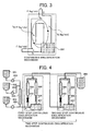
- Fig. 3 is a schematic diagram illustrating the emulsification portion and the accumulation portion in a continuous emulsification mechanism having a single continuous emulsification unit.
- the width of the illustrated pipe corresponding to the circulation portion varies therein. This is intentionally exaggerated to visially illustrate the increase and decrease of the liquid flow rate.
- the total flow rate of the liquid before emulsification supplied to the continuousemulsification mechanism isrepresented by F(kg/min)
- the flow rate of the slurry and the liquid before emulsification passing through the emulsification portion which are emulsified dispersed therein is represented by Q (kg/min)
- how many times (the number of passing times) the liquid before emulsification which is to be emulsified to form the slurry have passed through the emulsification device before the slurry is discharged from the continuous emulsification mechanism is represented by n times.
- the flow rate of the slurry discharged through the outlet (Z) is also F (kg/min) based on the overflow principle. Therefore, the liquid emulsification is newly and continuously supplied at a flow rate of F (kg/min) to the slurry circulating in the circulation portion formed between the outlet (Z) and the inlet (A) at the theoretical flow rate of (Q - F) (kg/min).
- the mixture liquid formed of the slurry already ciarulating in the circulaintg pipe portion and the liquid before emulsification after the liquid before emulsification is thrown in is considered to achieve a sufficiently uniform state.
- the ratio of the liquid before emulsification to the mixture liquid of the liquid before emulsification and the slurry already ciarulating in the circulaintg pipe portion is F/Q.
- the liquid before emulsification taking a ratio of F/Q in the mixture receives a first shearing to form part of the slurry when the liquid before emulsification passes through the emulsification device (007) .
- the slurry already circulating in the circulaintg pipe portion taking a ratio of (1 - Q/F) in the mixture also receives another shearing, resulting in an increase in the number of its passing times by one.
- the mixture i.e., the slurry and the newly emulsified slurry
- F flow rate
- the overflown mixture completes with emulsification.
- the overflown mixture contains the newly formed slurry which has received one shearing at a ratio of F/Q.
- What is existent in the overflown mixture having the remaining ratio of (1-F/Q) is the slurry already circulating in the accumulation portion which have received shearing at least twice. That is, the toner particles which have been sheared only once is contained in the overflown mixture complete with emulsification at the rate of F/Q.
- the slurry which have been sheared only once and are still circulating in the accumulation potion without overflowing from the accumulation portion through the outlet (Z) also have a ratio of F/Q in the slurry still in circulation.
- the flow rate of the liquid circulating between the outlet (Z) and the inlet (A) is (Q -F) (kg/min).
- the slurry which have been sheared only once after newly and continuously supplied liquid before emulsification at a flow rate of F (kg/min) through the inlet (A) is contained at a ratio of ⁇ (F/Q) ⁇ (Q - F) ⁇ / ⁇ (Q - F) + F ⁇ in the mixture.
- Fig. 2 is obtained as a result of the considerations for practial rganges of Q and F.
- toner paraticles i.e., the overflown slurry
- the emulsification portion which have passsed through the emulsification portion a small number of times occupy a large ratio in the slurry overflown through the outlet (Z), i.e., the slurry complete with emulsification.
- the particles having a small number of passes have a large particle diameter and can be a major cause of deterioration of Dv/Dn of the slurry complete with emulsification. Therefore, the inventors of the present invention have intensively studied on to what degree the ratio of the toner particle having a small number of passes should be restrained to make Dv/Dn closer to 1.00 and to obtain a toner having a sharp particle size distribution.
- the inventors of the present invention have also studied whether the ratio of the toner having a small mnumber of passes can be further decreased by improving a continuous emulsification mechanism other than the conditions regarding the continuous emulsification. As a result, it is found that the ratio of the toner particles having a small number of passes can be further decreased by using a continuous emulsification mechanism having multiple continuous emulsification units.
- Part of the liquid emulsified in the first continuous emulsification unit is discharged through an outlet (B) of the first step continuous emulsification unit at a flow rate of F (kg/min) to the second step continuous emulsification unit through an inlet (C) thereof.
- Part of the emulsified liquid at the second step continuous emulsification unit is discharged through the outlet (Z) to the retriving tanl (009) as the liquid complete with emulsification and liquid droplet toner particles.
- Fig. 6 is a schematic diagram of Fig. 4 illustrating an example of the two-step continuous emulsification mechanism. Based on the simulation calculation of the number of passing times for a two-step continuous emulsification mechanism, the simulation calculation of the number of passing times for the three or more-step continuous emulsification mechanism is described. The result of the simulation for a two-step continuous emulsification mechanism is shown in Fig. 5. Fig. 6 is illustrated in the same manner as illustrated in Fig.
- F (kg/min) represents a flow rate of the liquid before emulsification fed through the nilet (A) to the first step continuous emulsification unit of a two-step continuous emulsification mechanism and a flow rate of the slurry overflwon to the the second step continuous emulsification unit of a two-step continuous emulsification mechanism.
- 1 Q (kg/min) represents a flow rate of the slurry and the liquid before emulsification passing through the continuous emulsification portion of the first step continuous emulsification unit of a two-step continuous emulsification mechanism
- 2 Q represents a flow rate of the slurry passing through the continuous emulsification portion of the second step continuous emulsification unit of a two-step continuous emulsification mechanism.
- n1 (n1 is an integer not less than 1) represents how many times the liquid before emulsification have passed through the continuous emulsification portion of the first step continuous emulsification unit of the two-step continuous emulsification mechanism and n2 (n2 is an integer not less than 1) represents how many times the slurry overflown from the first step continuous emulsification unit have passed through the continuous emulsification portion of the second step continuous emulsification unit of the two-step continuous emulsification mechanism.
- t i.e., na + n2 times.
- the liquid before emulsification are sheared at least twice, that is, a first pass at the first-step emulsification portion and a second pass at the second-step emulsification portion.
- the basic concept for use in calculating the exisiting ratio ( ⁇ 12 W 3 ) of the toner particles which have been sheared three times only is described below contained in the liquid complete with emulsification overflwon through the outlet (Z).
- the slurry overflown through the inlet (C) to the second step has been already sheared in the first-step continuous emulsification unit at least once.
- the slurry overflown through the inlet (C) at a flow rate of F (kg/min) is continuously fed to the slurry circulating in the circulation portion in the second-step continuous emulsification unit at a flow rate of ( 2 Q - F) (kg/min).
- the mixture of the slurry overflown from the first step continuous emulsification unit and the slurry already circulating in the circulation portion of the second step continuous emulsification unit is considered to be sufficiently uniformely mixed.
- the ratio of the slurry overflown from the first step continuous emulsification unit to the mixture of the slurry overflown from the first step continuous emulsification unit and the slurry already circulating in the circulation portion of the second step continuous emulsification unit is F/ 2 Q.
- the ratio ( 1 W 1 ) of the slurry which have passed through the continuous emulsification portion of the first-step continuous emulsification unit only once to the slurry overflwon from the first-step continuous emulsification unit is F/Q ⁇ 100 (%)
- the ratio ( 1 W 2 ) of the slurry which have passed through the continuous emulsification portion of the first-step continuous emulsification unit only twice to the slurry overflwon from the first-step continuous emulsification unit is F/ 1 Q ⁇ (1 - F/ 1 Q) ⁇ 100 (%).
- ⁇ 12 W 3 (%) is presented by the sum of the ratio ⁇ ( 1 W 1 100) ⁇ (F/ 2 Q ⁇ (1 - F/ 2 Q) ⁇ 100) ⁇ (%) + the ratio ⁇ ( 1 W 2 /100) ⁇ (F/ 2 Q ⁇ 100) ⁇ (%).
- the exisiting ratio ( 2 W n2 ) (%) of the slurry passing through the emulsification porition of the second continuous emulsification unit n2 times before overflown to the next continuous emulsification unit to the slurry overflown thereto is represented by F/ 2 Q ⁇ (1 - F/ 2 Q) n2-1 ⁇ 100.
- k-1 i.e., k-1 W n(k-1) (%) is represented by F/ k-1 Q ⁇ (1 ⁇ F/ 1-k Q) n(k-1)-1 ⁇ 100.
- the existing ratio of the slurry for the combination of (n1 + n2 + • • • + nk) is represented by 1 W n1 /100 ⁇ 2 W n2 /100 ⁇ • • • ⁇ k-1 Wn (k-1) /100 ⁇ F/ k Q ⁇ (1 - F/ k Q) nk-1 ⁇ 100.
- the relationship (2) represents a calculating formula for W in the right hand side of the relatinoship (1).
- the relationship (2) well represents the description mentioned above. That is, in the right-hand side of the relationship (2), ( 1 W n1 /100) is an coefficient (but not a constant) of (F/ 2 Q) ⁇ ⁇ 1 - (F/ 2 Q) n2-1 ⁇ 100 ⁇ and a significantly small figure (i.e., less than 1.0). In other words, that is the coefficient serving to decreasing the value ( 12 W t ) of the left-hand side based on (F/ 2 Q) ⁇ ⁇ 1 - (F/ 2 Q) n2-1 ⁇ 100 ⁇ .
- the degree of the decrease increases as the value of (F/ 2 Q) ⁇ ⁇ 1 - (F/ 2 Q) n2-1 ⁇ 100 ⁇ decreases, i.e., the number of passes at the second-step continuous emulsification and/or dispersion mechanism decreases.
- the degree of the decrease increases as the value of ( 1 W n1 /100) decreases, i.e., the number of passes at the first-step continuous emulsification unit decreases.
- Fig. 5 is obtaiend according to the basic simulation described above.
- the distribution curve is convex upward to the contray to the graph shown in Fig. 2, in which the toner particles having a smaller number of passes occupies a large ratio. Therefore, according to the present invention, the existing ratio of the toner particles having a small number of passes in the liquid complete with emulsification can be significantly decreased.
- the simulation described above can be applied to the case of a continuous emulsification mechanism having k continuous emulsification uints. It is found that the width of the distribution becomes narrow in these cases, resulting in unifomization of the number of passes. As a result, it is confirmed that the prevention effect of discharging toner particles having a small number of passes is high as k increases.
- the content ratio of toner particles having a small number of passes confirmed by experiments is as follows: in a continuous emulsifcation mechanism having k continuous emulsification units, to obtain high qulaity and grade images, it is preferred that the sum of the existing ratio of toner particles having 6 time passes at maximum ( ⁇ 1k W 6 ) satisfies the following relationship: 1/k (%) ⁇ ⁇ 1k W 6 ⁇ 30/k (%): and the sum of the existing ratio of toner particles having 3 time passes at maximum ( ⁇ 1k W 3 ) satisfies the following relationship: 0.5/k (%) ⁇ ⁇ 1k W 3 ⁇ 15/k (%).
- Toner particles having a small number of passes have a large particle diameter, which has an adverse impact on Dv/Dn. Therefore, it is understandable to jump to an easy conclusion that just increasing the number of passes for a liquid is enough simply by, for example, restraining the amount of the liquid supplied to the process of continuous emulsification or increasing the volume of the accumulation portion. But this in not true. Toner particles having excessive number of passes tend to agglomerate, which makes the particle diameter larger to the contrary. That is, there is a suitable number of passes for toner particles. With regard to this suitable number of passes, in the present invention, a suitable range is set based on the concept of the average number of passes through an emulsification device.
- the average number N AV of all particles passing through an emulsification device is Q/F.
- the number of passes increases, the amount of supply decreases, which means reduction of production. This provides another reason for restriction on the upper limit of the average number of passing through an emulsification device and the lower limit of the existing ratio of toner particles having a small number of passes in the liquid complete with emulsification.
- the flow rate of the liquid before emulsification overflown to the continuous emulsification mechanism and the slurry over flown to the next continuous emulsification unit or the retrieving tank is represented by F (kg/min).
- k 1, 6 ⁇ N AV ⁇ 100.
- the difference betweenn any of p V (kg) in the continuous emulsfication mechanism is preferably not greater than 10 kg.
- the circumference speed of the emulsfication stirring blade provided in the emulsifcation device of the continuous emulsifciation portion in the continuous emulsification mechanism is preferebly from 10 to 24 m/sec to obtain toner particles having a uniform particle diameter. Furthermore, the difference between the maximum speed and the minimum speed of the emulsfication stirring blade is preferably not greater than 10 m/s.
- the amount of liquid supply i.e., production of the liquid complete with emulsification, increases not less than k times, meaning significant improvement inproduction capability.
- the discharing ratio of toner particles having a small number of passes can be decreased, there is a merit in terms of quality of the toner particles obtained.
- emulsification device of the present invention Various kinds of marketed devices can be used as an emulsification device of the present invention.
- Specific examples of such devices include continuous emulsion devices such as ULTRA-TURRAX® (manufactured by IKA-WERKE GMBH & CO., KG.), POLYTRON (manufactured by Kinematica AG), TK auto homomixer (manufactued by Tokushu Kika Kogyo Co., Ltd.), Ebara Milder (manufactured by Ebara Coproration), TK pipeine homomixer, and TK HOMOMIC LINE FLOW (manufactued by Tokushu Kika Kogyo Co., Ltd.), Colloid mill (manufactured by Kobelco Eco-Solutoins Co.
- ULTRA-TURRAX® manufactured by IKA-WERKE GMBH & CO., KG.
- POLYTRON manufactured by Kinematica AG
- a continuous emulsification mechanism is formed of an accumulation portion including the volume of an emulsification portion and the volume of the circulation portion.
- a continuous emulsification mechanism can be structured from a batch-type emulsification device by changing its stock tank to which liquid is supplied to an overflow type stock tank.
- the stock tank volume can be used as an acumulation portion.
- the accumulatino portion can have a loop form.
- the volume average particle diameter (Dv) based on volume calculated by the volume distribution of a toner is preferably not greater than 10 ⁇ m.
- the volume average particle diameter (Dv) based on volume calculated by the volume distribution of a toner is preferably not greater than 10 ⁇ m.
- such a toner preferably has a particle diameter not less than 3 ⁇ m.
- the number of toner particles having a greatly small particle diameter, which is not easily developed, increases on the surface of carrier particles or a developing roller especially when toner particles having a particle diameter not greater than 2 ⁇ m occupies not less than 20 %. Therefore, the remaining toner particles do not sufficiently contact and/or abrade with a magnetic carrier or a developing roller and tend to be reversely charged, which causes background fouling. Therefore, the quality of images is degraded.
- the particle size distribution represented by the value (Dv/Dn) calculated by dividing the volume average particle diameter (Dv) of a toner with the number average particle diameter (Dn) based on number obtained from number distribution is preferably from 1.05 to 1.25.
- the particle size distribution is sharp, the toner charge amount distribution is uniform, which leasds to decrease in occurence of background fouling.
- Dv/Dn is too large, the charge amount distribution in a toner is wide so that it is difficult to obtain a high grade image.
- the toner particle described above is obtaiend by measuring the particle diameter of 50,000 particles using Coulter Counter Multisizer (manufactured by Backman Coulter, Inc.) with a selection of an aperture having a measuring hole of 50 ⁇ m to deal with the particle diameter of the toner particle to be measured.
- Coulter Counter Multisizer manufactured by Backman Coulter, Inc.
- polyester resins are preferred for reproduction of a full color image in light of fixability.
- unmodified resins are preferred in which there is a linkage group other than an ester linkage formed of monomer units of an acid or an alcohol contained in a polyester resin, or in which a resin component having a different structure is linked with a covalent linkage, an ion linkage, etc., in a polyester resin.
- an unmodified polyester resin formed of a linkage other than ester linkage at its end.
- an unmodified polyester resin can be included which is formed by introducing a function group, such as an isocyanate group, reactive with an acid group or a hydroxyl group at the end and reacting the function group with an active hydrogen compound to modify or elongate the end.
- a resin in which the ends of the polyester are linked with each other can be included (e.g., urea modified polyesters and urethane modified polyesters).
- resins which are formed by introducing a reactive group such as a double linkage in the polyester main chain and thereafter introducing a graft component of a carbon-carbon linkage in a side chain thereof by generating a radical polymerization or linking double linkages with each other.
- resins include a styrene-modified polyester resin and an acrylic-modified polyester resin.
- resins which are formed by copolymerizing a resin component having a different structure in the main chain of a polyester resin, or reacting a polyester resin with a compound having a carboxyl group and/or a hydroxyl group at its end, for example, copolymerizing with a silicone resin the end of which is modified by a carboxyl group, a hydroxyl group, an epoxy group and a mecapto group (e.g., silicone modified polyesters).
- urea modified polyester resins (i) include a reactant product of a polyester prepolymer (A) having an isocyanate group with an amine (B).
- Specific examples of the polyester prepolymer (A) having an isocyanate group include a compound prepared by reacting a polyester, i.e., a polycondensation product of a polyol (1) and a polycarboxylic acid (2) having an active hydrogen group, with a polyisocyanate (3).
- polyols (1) are diols (1-1) and polyols (1-2) having at least 3 hydroxyl groups.
- the diol (1-1) alone or in combination with a small quantity of the polyols (1-2) are preferred as the polyol (1).
- diols (1-1) are alkylene glycols (e.g., ethylene glycol, 1,2-propylene glycol, 1,3-propylene glycol, 1,4-butane diol and 1,6-hexan diol), alkylene ether glycol (e.g., diethylene glycol, triethylene glycol, dipropylene glycol, polyethylene glycol, polypropylene glycol, and polytetra methylene ether glycol), alicyclic diols (e.g., 1,4-cyclo hexane dimethanol, hydrogen added bisphenol A, and bisphenol groups (e.g., bisphenol A, bisphenol F and bisphenol S), adducts of the alicyclic diols mentioned above with alkylene oxides (e.g., ethylene oxides, propylene oxides, butylene oxides), and the bisphenols mentioned above with alkylene oxides (e.g., ethylene oxides, propylene oxides and butylene oxides),
- alkylene glycols having 2 to 12 carbon atoms and adducts of bisphenol groups with alkylene oxides are preferred, and adducts of bisphenol groups with alkylene oxides and combinations of adducts of one or more bisphenols with one or more alkylene oxides and alkylene glycols having 2 to 12 carbon atoms are especially preferred.
- polyols (1-2) having at least 3 hydroxyl groups include aliphatic alcohols having 3 or more hydroxyl groups (e.g., glycerine, trimethylol ethane, trimethylol propane, pentaerythritol and sorbitol), polyphenols having at least 3 hydroxyl groups (e.g., trisphenol PA, phenol novolak and cresol novolak) and adducts of polyphenols having at least 3 hydroxyl groups with the alkylene oxides mentioned above.
- aliphatic alcohols having 3 or more hydroxyl groups e.g., glycerine, trimethylol ethane, trimethylol propane, pentaerythritol and sorbitol
- polyphenols having at least 3 hydroxyl groups e.g., trisphenol PA, phenol novolak and cresol novolak
- polycarboxylic acids (2) are dicarboxylic acids (2-1) and polycarboxylic acids (2-2) having at least 3 hydroxyl groups, with a dicarboxylic acid (2-1) alone or in combination with a small quantity of one or more polycarboxylic acids (2-2) being preferred as the polycarboxylic acid (2).
- dicarboxylic acids (2-1) include alkylene dicarboxylic acid (e.g., succinic acid, adipic acid and sebacic acid), alkenylene dicarboxylic acid (e.g., maleic acid and fumaric acid), and aromatic dicarboxylic acids (e.g., phthalic acid, isophthalic acid, terephthalic acid and naphthalene dicarboxylic acid).
- alkenylene dicarboxylic acids having 4 to 20 carbon atoms and the aromatic dicarboxylic acids having 8 to 20 carbon atoms are preferred.
- polycarboxylic acids (2-2) having at least 3 carboxyl groups include aromatic polycarboxylic acid having 9 to 12 carbon atoms (e.g., trimellitic acid and pyromellitic acid).
- the polycarboxylic acids (2) can be obtained by reacting acid anhydrides of the above-mentionedorloweralkylesters (e.g., methylesters, ethyl esters and isopropyl esters) with the polyols (1).
- the mixing ratio of the polyol (1) to the polydicarboxylic acid (2) i.e. , the equivalent ratio ([OH]/[COOH]) of a hydroxyl group [OH] to a carboxyl group [COOH] , is normally from 2/1 to 1/1, preferably from 1.5/1 to 1/1, and more preferably from 1. 3/1 to 1.02/1.
- polyisocyanates (3) include aliphatic polyisocyanates (e.g., tetramethylene diisocyanate, hexamethylene diisocyanate and 2, 6-diisocyanate methylcaproate); alicyclic polyisocyanates (e.g., isophorone diisocyanate and cyclohexyl methane diisocyanate); aromatic diisocyanates (e.g., tolylene diisocyanate and diphenylmethane diisocyanate); aromatic aliphatic diisocyanates (e.g., ⁇ , ⁇ , ⁇ ' , ⁇ ' -tetramethyl xylylene diisocyanate) ; isocyanurates; and blocked polyisocyanates in which the polyisocyanates mentioned above are blocked with phenolderivatives,oximesor caprolactams. These compounds can be used alone or in combination.
- aliphatic polyisocyanates e.g., t
- the mixing ratio of the polyisocyanate (3) to the polyester i.e. , the equivalent ratio ([NCO] /[OH]) of an isocyanate group [NCO] to a hydroxyl group [OH] of a polyester having hydroxyl groups, is normally from 5/1 to 1/1, preferably from 4/1 to 1.2/1, and more preferably from 2.5/1 to 1.5/1.
- the [NCO] /[OH] ratio is too large, the low temperature fixability of the toner tends to deteriorate.
- the equivalent ratio of [NCO] /[OH] is too small, the urea content in the resultant modified polyesters decreases and thereby the anti-hot offset property of the toner tends to deteriorate.
- the content of the constitutional component, which is obtained from the polyisocyanate (3), in the prepolymer (A) having an isocyanate group at its end portion is from 0. 5 to 40 % by weight, preferably from 1 to 30 % by weight and more preferably from 2 to 20 % by weight.
- the content is too small, the hot offset resistance of the toner tends to deteriorate and in addition it is hard for the toner to have good heat resistance and low temperature fixability. In contrast, when the content is too large, the low temperature fixability of the toner tends to deteriorate.
- the number of isocyanate groups included in the prepolymer (A) per molecule is normally not less than 1, preferably from 1.5 to 3, and more preferably from 1.8 to 2.5. When the number of isocyanate groups is too small, the molecular weight of the modified polyester tends to decrease and thereby the anti-hot offset property tends to deteriorate.
- amine (B) examples include diamines (B1), polyamines (B2) having three or more amino groups, amino alcohols (B3), amino mercaptans (B4), amino acids (B5) and blocked amines (B6) in which the amines (B1-B5) mentioned above are blocked.
- diamines (B1) include aromatic diamines (e.g., phenylene diamine, diethyltoluene diamine and 4,4'-diaminodiphenyl methane); alicyclic diamines (e.g., 4,4'-diamino-3,3'-dimethyldicyclohexyl methane, diaminocyclohexane and isophoron diamine) ; aliphatic diamines (e.g., ethylene diamine, tetramethylene diamine and hexamethylene diamine); etc.
- polyamines (B2) having three or more amino groups include diethylene triamine, and triethylene tetramine.
- Specific preferred examples of the amino alcohols (B3) include ethanol amines and hydroxyethyl anilines.
- Specific examples of the amino mercaptans (B4) include aminoethyl mercaptans and aminopropyl mercaptans.
- Specific preferred examples of the amino acids (B5) include amino propionic acids and amino caproic acids.
- Specific examples of the blocked amines (B6) of B1 to B5 include ketimine compounds which are prepared by reacting one of the amines B1-B5 mentioned above with a ketone such as acetone, methyl ethyl ketone and methyl isobutyl ketone; oxazoline compounds, etc. Among these amines(B), B1 and a mixture of B1 and a small quantity of B2 are preferred.
- the molecular weight of the urea-modified polyester resins (i) can be controlled using a molecular-weight control agent, if desired.
- the molecular-weight control agent examples include monoamines (e. g. , diethyle amine, dibutyl amine, butyl amine and lauryl amine), and blocked amines (e.g., ketimine compounds) prepared by blocking the monoamines mentioned above.
- monoamines e. g. , diethyle amine, dibutyl amine, butyl amine and lauryl amine
- blocked amines e.g., ketimine compounds
- the mixing ratio of the amines (B) to the prepolymer (A), i. e., the equivalent ratio ([NCO] /[NHx]) of the isocyanate group [NCO] contained in the prepolymer (A) to the amino group [NHx] contained in the amines (B), is normally from 1/2 to 2/1, preferably from 1.5/1 to 1/1.5 and more preferably from 1.2/1 to 1/1.2.
- X is 1 or 2, and mostly 2.
- the urea-modified polyester (i) can include a urethane linkage as well as a urea linkage.
- the molar ratio of the content of the urea linkage to the content of the urethane linkage is normally from 100/0 to 10/90, preferably from 80/20 to 20/80 and more preferably from 60/40 to 30/70.
- the anti-hot offset property of the resultant toner deteriorates.
- the urea-modified polyester (i) of the present invention can be prepared by a method such as one-shot methods or prepolymer methods.
- the weight average molecular weight of the urea-modified polyester (i) is not less than 10, 000, preferably from 20,000 to 10,000,000 and more preferably from 30,000 to 1,000,000. When the weight average molecular weight is too small, the hot offset resistance of the resultant toner tends to deteriorate.
- the number average molecular weight of the modified polyester (i) is not particularly limited if the weight average molecular weight mentioned above is allowed.
- the number average molecular weight is normally not less than 20,000, preferably from 1000 to 10,000 and more preferably from 2,000 to 8,000.
- the number average molecular weight is too large, low temperature fixability of the resultant toner tends to deteriorate and, in addition, the gloss properties thereof also tend to deteriorate when the toner is used in a full color device.
- the unmodified polyester (ii) can be contained as a binder resin in combination with the modified polyester (i).
- the combinational use of modified polyester (i) and the unmodified polyester (ii) is preferred because the low temperature fixability and gloss property when the toner is used in a full color device can be improved by the combinational use.
- Specific preferred examples of the unmodified polyester resins (ii) include polycondensation products of polyol (1) and polycarboxylic acid (2) as mentioned above for use in the polyester constituents of the modified polyester (i) mentioned above.
- the unmodified polyester resins (ii) are the same as those for the modified polyester resins (i) .
- the unmodified polyester resins (ii) include not only unmodified polyesters but also polyester resins modified by a chemical linkage other than urea linkage, for example, urethane linkage. It is preferred that (i) and (ii) are at least partially mixed with each other in light of the low temperature fixability and anti-hot offset property. Therefore, it is preferred, but not mandatory, that the unmodified polyester resins (ii) have a similar composition to that of the polyester component of the unmodified polyester resins (i) .
- the weight ratio of (i) / (ii) is normally from 5/95 to 80/20, preferably from 5/95 to 30/70, more preferably from 5/95 to 25/75 and even more preferably from 7/93 to 20/80 when (ii) is contained.
- the weight ratio of the modified polyester (i) is too small, the anti-hot offset property of the toner tends to deteriorate and in addition it is disadvantageous for the toner to have a good combination of a high temperature preservability and a low temperature fixability.
- the peak weight average molecular weight of the unmodified polyester (ii) is normally from 1,000 to 30, 000, preferably from 1,500 to 10, 000, and more preferably from 2, 000 to 8, 000. When the peak molecular weight is too small, the high temperature preservability tend to deteriorate. When the peak molecular weight is too large, the low temperature fixability tends to deteriorate.
- the hydroxyl group value of the unmodified polyester resin (ii) is preferably not less than 5 mgKOH/g, more preferably from 10 to 120 mgKOH/g and even more preferably 20 to 80 mgKOH/g.
- the acid value of the unmodified polyester resin (ii) is normally from 1 to 30 mgKOH/g, and preferably from 5 to 20 mgKOH/g. When the (ii) has such an acid value, the resultant toner tends to be negatively charged.
- the resin as a toner binder preferably has a glass transition temperature (Tg) of from 50 to 70 °C, and more preferably from 55 to 65 °C.
- Tg glass transition temperature
- the glass transition temperature is too low, the high temperature preservability of the toner tends to deteriorate.
- the glass transition temperature is too high, the low temperature fixability tends to be insufficient. Since the unmodified polyester resin (ii) coexists with the urea-modified polyester resin (i), the dry toner of the present invention tends to have a good high temperature preservability even when the toner has a relatively low glass transition temperature compared with that of a known polyester-based toner.
- the resin as the toner binder preferably has a storage modulus of elasticity of 10, 000 dyne/cm 2 at a temperature (TG') not lower than 100 °C, and more preferably from 110 to 200 °C when measured at a frequency of 20 Hz.
- TG' temperature not lower than 100 °C
- the toner tend to have a poor anti-hot offset property.
- the toner binder preferably has a viscosity of 1,000 poise at a temperature (T ⁇ ) not higher than 180 °C, and more preferably from 90 to 160 °C. When the temperature T ⁇ is too high, the low temperature fixability of the toner tends to deteriorate.
- the temperature TG' of the toner is preferably higher than the temperature T ⁇ , i.e., the difference between TG' and T ⁇ ) (TG'-T ⁇ ) is preferably not less than 0 °C. More preferably, the difference is not less than 10 °C, and even more preferably not less than 20 °C. There is no specific upper limit to the difference. However, in view of good combination of high temperature preservability and low temperature fixability, the difference (TG' - T ⁇ ) is preferably from 0 to 100 °C, more preferably from 10 to 90 °C, and even more preferably from 20 to 80 °C.
- Suitable colorants for use in the toner component of the present invention include any known dyes and pigments.
- colorants include carbon black, Nigrosine dyes, black iron oxide, Naphthol YellowS, Hansa Yellow (10G, 5G and G), Cadmium Yellow, yellow iron oxide, loess, chrome yellow, Titan Yellow, polyazo yellow, Oil Yellow, Hansa Yellow (GR, A, RN and R), Pigment Yellow L, Benzidine Yellow (G and GR), Permanent Yellow (NCG), Vulcan Fast Yellow (5G and R), Tartrazine Lake, Quinoline Yellow Lake, Anthrazane Yellow BGL, isoindolinone yellow, red iron oxide, red lead, orange lead, cadmium red, cadmium mercury red, antimony orange, Permanent Red 4R, Para Red, Fire Red, p-chloro-o-nitroaniline red, Lithol Fast Scarlet G, Brilliant Fast Scarlet, Brilliant Carmine BS, Permanent Red (F2R, F4R, FRL, FRLL and F4RH), Fast Scarlet VD, Vulcan Fast Rubine B, Brilliant Scarlet G, Lithol Rubine B,
- the content of the colorant is preferably from 1 to 15 % by weight, and more preferably from 3 to 10 % by weight, based on the total weight of the toner component.
- Master batch pigments which are prepared by combining a colorant with a resin, can be used as the colorant of the toner composition of the present invention.
- the resins for use in the master batch pigments or for use in combination with master batch pigments include the modified and unmodified polyester resins mentioned above; styrene polymers and substituted styrene polymers such as polystyrene, poly-p-chlorostyrene and polyvinyltoluene; styrene copolymers such as styrene-p-chlorostyrene copolymers, styrene-propylene copolymers, styrene-vinyltoluene copolymers, styrene-vinylnaphthalene copolymers, styrene-methyl acrylate copolymers, styrene-ethyl acrylate copolymers, styrene-butyl
- the master batch mentioned above is typically prepared by mixing and kneading a resin and a colorant upon application of high shear stress thereto.
- an organic solvent can be used to boost the interaction of the colorant with the resin.
- flushing methods in which an aqueous paste including a colorant is mixed with a resin solution of an organic solvent to transfer the colorant to the resin solution and then the aqueous liquid and organic solvent are separated to be removed can be preferably used because the resultant wet cake of the colorant can be used as it is.
- three-roll mills can be preferably used for kneading the mixture upon application of high shear stress thereto.
- a wax can be included as a release agent as part of the toner composition of the present invention.
- the release agent include polyolefin waxes such as polyethylene waxes and polypropylene waxes; long chain hydrocarbons such as paraffin waxes and SAZOL waxes; waxes including a carbonyl group, etc.
- polyolefin waxes such as polyethylene waxes and polypropylene waxes
- long chain hydrocarbons such as paraffin waxes and SAZOL waxes
- waxes including a carbonyl group etc.
- the waxes including a carbonyl group are preferred.
- waxes including a carbonyl group include polyalkane acid esters such as carnauba wax, montan waxes, trimethylolpropane tribehenate, pentaerythritol tetrabehenate, pentaerythritol diacetate dibehenate, glycerin tribehenate, and 1,18-octadecanediol distearate; polyalkanol esters such as trimellitic acid tristearyl, and distearyl maleate; polyalkylamide such as trimellitic acid tristearylamide; dialkyl ketone such as distearyl ketone, etc. Among these materials, polyalkane acid esters are preferred.
- the waxes for use in the toner of the present invention preferably have a melting point of from 40 to 160 °C, more preferably from 50 to 120 °C, and even more preferably from 60 to 90 °C.
- a melting point of the wax included in the toner is too low, the high temperature preservability of the toner tends to deteriorate.
- the melting point is too high, a cold offset tends to occur during fixing at a low temperature.
- the wax used in the toner composition of the present invention preferably has a melt viscosity of from 5 to 1, 000 cps and more preferably from 10 to 100 cps at a temperature 20 °C higher than the melting point of the wax.
- the content of the wax in the toner is from 0 to 40 % by weight and preferably from 3 to 30 % by weight based on the total weight of the toner.
- a charge controlling agent may be included as the toner component of the present invention.
- charge controlling agent examples include known charge controlling agents such as Nigrosine dyes, triphenylmethane dyes, metal complex dyes including chromium, chelate compounds of molybdic acid, Rhodamine dyes, alkoxyamines, quaternary ammonium salts (including fluorine-modified quaternary ammonium salts), alkylamides, phosphor and compounds including phosphor, tungsten and compounds including tungsten, fluorine-containing activators, metal salts of salicylic acid, metal salts of salicylic acid derivatives, etc.
- charge controlling agents such as Nigrosine dyes, triphenylmethane dyes, metal complex dyes including chromium, chelate compounds of molybdic acid, Rhodamine dyes, alkoxyamines, quaternary ammonium salts (including fluorine-modified quaternary ammonium salts), alkylamides, phosphor and compounds including phosphor, tungsten and compounds including tungs
- Specific examples of the marketed products of the charge controlling agents include BONTRON 03 (Nigrosine dyes), BONTRON P-51 (quaternary ammonium salt), BONTRON S-34 (metal-containing azo dye), E-82 (metal complex of oxynaphthoic acid), E-84 (metal complex of salicylic acid), and E-89 (phenolic condensation product), which are manufactured by Orient Chemical Industries Co., Ltd.
- TP-302 and TP-415 molybdenum complex of quaternary ammonium salt
- COPY CHARGE PSY VP2038 (quaternary ammonium salt), COPY BLUE (triphenyl methane derivative), COPY CHARGE NEG VP2036 and NX VP434 (quaternary ammonium salt), which are manufactured by Hoechst AG; LRA-901, and LR-147 (boron complex), which are manufactured by Japan Carlit Co., Ltd.
- the content of the charge controlling agent is determined depending on the species of the binder resin used, whether or not an additive is added and toner manufacturing method (such as dispersion method) used, and is not particularly limited.
- the content of the charge controlling agent is from 0.1 to 10 parts by weight, and preferably from 0.2 to 5 parts by weight, per 100 parts by weight of the binder resin included in the toner.
- the content is too high, the toner tends to have too large chargeability, and thereby the electrostatic force of a developing roller attracting the toner increases, resulting in deterioration of the fluidity of the toner and a decrease of the image density of toner images.
- the charge controlling agent can be dissolved or dispersed in an organic solvent after kneaded together with a master batch pigment and resin.
- the charge controlling agent can be directly dissolved or dispersed in an organic solvent when the toner constituents are dissolved or dispersed in the organic solvent.
- the mixing and dispersion are preferably preformed by a typical mixer having a stirring device, and more preferably by a homogenizer or a high pressure homogenizer having a high speed rotation body and a stator, or a device in which the content is sufficiently uniformly dispersed such as a dispersion device, for example, a ball mill, a beads mill, and a sand mill using media.
- a dispersion device for example, a ball mill, a beads mill, and a sand mill using media.
- Water can be used alone or in combination with a water soluble solvent as the aqueous medium for use in the present invention.
- water soluble solvents include alcohols (such as methanol, isopropanol and ethylene glycol), dimethylformamide, tetrahydrofuran, cellosolves (such as methyl cellosolve) and lower ketones (such as acetone and methyl ethyl ketone).
- Emulsified droplets of a uniform dispersion body of these resins, colorant, etc. are formed in an aqueous medium using an emulsification device.
- an emulsification device There is no specific limit to the methods of emulsification. Known methods such as a low speed shearing type method, a high speed shearing type method, a friction type method, a high pressure jet type method, and supersonic type method can be used. It is preferred to use a high speed shearing type method to obtain a dispersion body having a particle diameter of from 2 to 20 ⁇ m.
- an emulsification device having a rotation blade Any marketed emulsification device can be used.
- Such devices include continuous emulsion and/or dispersion devices such as ULTRA-TURRAX® (manufactured by IKA-WERKE GMBH & CO., KG.), POLYTRON (manufactured by Kinematica AG), TK auto homomixer (manufactued by Tokushu Kika Kogyo Co., Ltd.), Ebara Milder (manufactured by Ebara Coproration),TK pipeine homomixer, and TK HOMOMIC LINE FLOW (manufactued by Tokushu Kika Kogyo Co.
- ULTRA-TURRAX® manufactured by IKA-WERKE GMBH & CO., KG.
- POLYTRON manufactured by Kinematica AG
- TK auto homomixer manufactured by Tokushu Kika Kogyo Co., Ltd.
- Ebara Milder manufactured by Ebara Coproration
- TK pipeine homomixer and TK HOMOMIC LINE FLOW
- Colloid mill manufactured by Kobelco Eco-SolutoinsCo., Ltd.
- Slusher and Trigonal wet type fine particle pulverizer
- Mitsui Mining Co., Ltd. and Cavitron
- Fine Fowmill manufactured by Pacific Machinery and Engineering Co., Ltd.
- Specific examples of such other devices include batch and/or continuous emulsion and/or dispersion devices such as Cleamix (manufactued by M technique Co., Ltd.), and FILMIX (manufactued by Tokushu Kika Kogyo Co., Ltd.).
- a high speed shearing type dispersion device When a high speed shearing type dispersion device is used, there is no specific limit to the number of rotation thereof. The number of rotation is preferably from 5,000 to 20,000 rpm and more preferably from 5, 000 to 20, 000 rpm. In addition, there is no specific limit to time for emulsion and/or dispersion. When a batch type device is used (for example, when one of feeding or emulsion and/or dispersion is a continuous type and the other is an intermittent type), the time is preferably from 0.1 to 5 minutes. As to the temperature during emulsification, it is preferably from 0 to 150 °C (under pressure), and preferably from 10 to 98°C. Ahightemperature is preferred in that emulsion and/or dispersoin tends to be easy since uniform dispersion bodies including a resin and a colorant, have a low viscosity.
- the resin achieves an elongation raction or cross-linkage reaction to form a toner binder.
- a prepolymer (A) and an amine (B) react in uniform dispersion bodies including a resin and a colorant to form a toner binder, which is a polyester modified by a urea linkage.
- the prepolymer (A) has one or more isocyanate groups and can be obtained by heating a polyol (1) and a polycarboxyl acid (2) between 150 to 280 °C in the presence of a known esterified catalyst such as tetra butoxy titanate and dibutyl tin oxide to form a polyester having a hydroxyl group obtained by removing water under reduced pressure if necessary, and further reacting a polyisocyanate (3) with the polyester thus obtained at 40 to 140 °C.
- a known esterified catalyst such as tetra butoxy titanate and dibutyl tin oxide
- solvents include compounds inactive to an isocyanate (3) such as: aromatic group solvents (for example, toluene and xylene); ketones (for example, acetone, methyl ethyl ketone, and methyl isobutyl keton) ; esters (for example, ethy acetate), amides (for example, dimethyl formaldehyde, and dimethyl acetoamide); and ethers (for example, tetrahydrofuran and dioxane).
- aromatic group solvents for example, toluene and xylene
- ketones for example, acetone, methyl ethyl ketone, and methyl isobutyl keton
- esters for example, ethy acetate
- amides for example, dimethyl formaldehyde, and dimethyl acetoamide
- ethers for example, tetrahydrofuran and dioxane
- an ummodified polyester (ii) which is not modified by a urea linkage and is prepared in the same method as that for use in preparing a polyester having a hydroxyl group, is used in combination, the unmodified polyester (ii) is dissolved and mixed in the solution in which the reaction of the (i) mentioned above is complete.
- the time to be taken for the elongation or cross likage reaction is determined (selected) depending on the reaction property of the combination of the isocyanate structure contained in a prepolymer (A) and an amine (B).
- the time is preferably from 10 minutes to 40 hours, and more preferably from 2 to 24 hours.
- the temperature during raction is preferably from 0 to 150 °C, and more preferably from 40 to 98 °C.
- known catalysts can be used if desired. Specific examples of such catalysts include dibutyl tin laurate, and dioctyl tin laurate.
- a volatile organic solvent which can dissolve, for example, the modified polyester resin (i) and the prepolymer (A), is used to decrease the viscosity of an oil phase containing a toner component, and to enable emulsification.
- Volatile organic solvents having a boiling point lower than 100 °C are preferred because such solvents are easy to be removed.
- solvents include toluene, xylene, benzene, carbon tetrachloride, methylene chloride, 1,2-dichloroethane, 1,1,2-trichloroethane, trichloroethylene, chloroform, monochlorobenzene, dichloroethylidene, methyl acetate, ethyl acetate, methylethyl ketone, and methyl isobutyl ketone. These can be used alone or in combination.
- aromatic solvents such as toluene and xylene
- halogenated hydrocarbons such as methylene chloride, 1,2-dichloroethane, chloroform and carbon tetrachloride
- a solvent soluble to an aqueous medium such as alcohol and water in combination.
- the content of such a solvent is preferably from 10 to 900 parts based on 100 parts of a toner component.
- Emulsified and/or dispersed droplets to make toner particldes can be formed by reacting a dispersant formed of a toner component containing a prepolymer (A) having an isocyanate group, other resins, a colorant, etc., with an amine (B) in an aqueous medium as mentioned above. It is also possible to use a modified polyester (i), which is manufactured in adivance.
- a dispersant can be used to stably form emulsified and/or dispersed droplets in an aqueous medium.
- Various kinds of dispserancts can be used. The kinds of the dispersants are described below.
- a solid particulate dispersant is present in a solid form hardly soluble to water in an aqueous medium and preferably has an average particle diameter of from 0.01 to 1 ⁇ m.
- inorganic solid particulate dispersants include silica, alumina, titanium oxide, barium titanate, magnesium titanate, calcium titanate, strontium titanate, zinc oxide, tin oxide, quartz sand, clay, mica, sand-lime, diatom earth, chromium oxide, cerium oxide, red iron oxide, antimony trioxide, magnesium oxide, zirconium oxide, barium sulfate, barium carbonate, calcium carbonate, silicon carbide, and silicon nitride. More preferred specific examples of the inorganic dispersants include tricalcium phosphate, calcium carbonate, colloidal titanium oxide, colloidal silica, and hydroxyapatite. Among them, hydroxyapatite which is synthesized by reacting natrium phosphate and calcium chlorinate in water (or water containing a water solble solvent) a under basic condition is especially preferred.
- organic solid particulates include fine crystal of organic compounds having a low molecular weight, polymer particulates having a high molecular weight, such as polystyrene which is copolymerized with a monomer having a carboxyl group such as a methacrylic acid ester which can be prepared by a method such as soap free emulsion polymerization, suspension polymerization or dispersion polymerization, copolymers of a methacrylic acid ester or an acrylic acid ester, polycondensation resins such as silicone, benzoguanamine and nylon, and polymer particles of thermosetting resins.
- polystyrene which is copolymerized with a monomer having a carboxyl group such as a methacrylic acid ester which can be prepared by a method such as soap free emulsion polymerization, suspension polymerization or dispersion polymerization, copolymers of a methacrylic acid ester or an acrylic acid ester, polycondensation resins such as
- an inorganic substance such as tricalcium phosphate soluble to an acid is made to be partially dissolved in advance by adding a suitable amount of an acid such as hydrochloric acid.
- the amount of the acid added is preferably from 0.01 to 10 %, and more preferably from 0. 1 to 5 % based on the amount thereof by which the whole of the inorganic substance can be totally dissolved.
- a solid particulate dispersant soluble to an alkali such as polymer particulates copolymerized with methacrylic acid having one or more carboxyl groups
- a base such as sodium hydrate
- the amount of the acid added is preferably from 0.01 to 10 %, and more preferably from 0.1 to 5 % based on the amount thereof by which the whole of the inorganic substance can be totally dissolved.
- dispersant added during or after emulsification on a necessity basis include anionic surfactants such as alkylbenzene sulfonic acid salts, ⁇ -olefin sulfonic acid salts, and phosphoric acid salts; cationic surfactants such as amine salts (e.g., alkyl amine salts, aminoalcohol fatty acid derivatives, polyamine fatty acid derivatives and imidazoline), and quaternary ammonium salts (e.g., alkyltrimethyl ammonium salts, dialkyldimethyl ammonium salts, alkyldimethyl benzyl ammonium salts, pyridinium salts, alkyl isoquinolinium salts and benzethonium chloride) ; nonionic surfactants such as fatty acid amide derivatives, polyhydric alcohol derivatives; and ampholytic surfactants such as alanine, dodecyldi(aminoethyl)
- a good dispersion can be prepared even with an extremely small amount thereof .
- the anionic surfactants having a fluoroalkyl group include fluoroalkyl carboxylic acids having from 2 to 10 carbon atoms and their metal salts, disodium perfluorooctanesulfonylglutamate, sodium 3- ⁇ omega-fluoroalkyl(C6-C11)oxy ⁇ -1-alkyl(C3-C4) sulfonate, sodium 3- ⁇ omega-fluoroalkanoyl(C6-C8)-N-ethylamino ⁇ -1-propanesulfo nate, fluoroalkyl(C11-C20) carboxylic acids and their metal salts, perfluoroalkylcarboxylic acids and their metal salts, perfluoroalkyl(C4-C12)sulfonate and their metal salts, perfluoro
- Such market products include SURFLON® S-111, S-112 and S-113, which are manufactured by Asahi Glass Co., Ltd.; FRORARD® FC-93, FC-95, FC-98 and FC-129, which are manufactured by Sumitomo 3M Ltd. ; UNIDYNE® DS-101 and DS-102, which are manufactured by Daikin Industries, Ltd.; MEGAFACE® F-110, F-120, F-113, F-191, F-812 and F-833 which are manufactured by Dainippon Ink and Chemicals, Inc.
- cationic surfactants having a fluoroalkyl group include primary, secondary or tertiary aliphatic amino acids, aliphatic quaternary ammonium salts (such as perfluoroalkyl(C6-C10)sulfoneamidepropyltrimethyl ammonium salts), benzalkonium salts, benzetonium chloride, pyridinium salts, imidazolinium salts, etc., all of which have a fluoroalkyl group
- Specific examples of commercially available products of these elements include SURFLON® S-121 (from Asahi Glass Co., Ltd.) ; FRORARD® FC-135 (from Sumitomo 3M Ltd.); UNIDYNE® DS-202 (from Daikin Industries, Ltd.); MEGAFACE® F-150 and F-824 (from Dainippon Ink and Chemicals, Inc.) ; ECTOP® EF-132 (from Tohchem Products Co., Ltd.); FU
- polymeric protection colloids include homopolymers and copolymers prepared using monomers such as acids (e.g., acrylic acid, methacrylic acid, ⁇ -cyanoacrylic acid, ⁇ -cyanomethacrylic acid, itaconic acid, crotonic acid, fumaricacid, maleicacidandmaleicanhydride), acrylicmonomers having a hydroxyl group (e.g., ⁇ -hydroxyethyl acrylate, ⁇ -hydroxyethyl methacrylate, ⁇ -hydroxypropyl acrylate, ⁇ -hydroxypropyl methacrylate, ⁇ -hydroxypropyl acrylate, ⁇ -hydroxypropyl methacrylate, 3-chloro-2-hydroxypropyl acrylate, 3-chloro-2-hydroxypropyl methacrylate, diethyleneglycolmonoacrylic acid esters, diethyleneglycolmonomethacrylic acid esters, glycerinmonoacrylic acid esters, N-methylolacrylamide
- polymers such as polyoxyethylene compounds (e.g., polyoxyethylene, polyoxypropylene, polyoxyethylenealkyl amines, polyoxypropylenealkyl amines, polyoxyethylenealkyl amides, polyoxypropylenealkyl amides, polyoxyethylene nonylphenyl ethers, polyoxyethylene laurylphenyl ethers, polyoxyethylene stearylphenyl esters, and polyoxyethylene nonylphenyl esters), and cellulose compounds such as methyl cellulose, hydroxyethyl cellulose and hydroxypropyl cellulose, can also be used as the polymeric protective colloid.
- polyoxyethylene compounds e.g., polyoxyethylene, polyoxypropylene, polyoxyethylenealkyl amines, polyoxypropylenealkyl amines, polyoxyethylenealkyl amides, polyoxypropylenealkyl amides, polyoxyethylene nonylphenyl ethers, polyoxyethylene laurylphenyl ethers, polyoxy
- the dispersant may remain on the surface of a toner particle. However, it is preferred in terms of toner charging that the remaining solid particulate dispersant is dissolved, washed with water, and removed after elongation and/or cross-linking reaction.
- Toner particles are prepared by such emulsification.
- the toner particles obtained have a wider particle size distribution than the predetermined particle size distribution (i.e., Dv/Dn is bad).
- Dv/Dn is bad
- deterioration of Dv/Dn is prevented by regulating the conditions during emulsification.
- the toner is subject to processes such as washing and drying toner following the emulsification process before a wet or dry clasiification process.
- a cyclon, a decanter, a centrifugal machine or an elbow jet machine are used. Unnecessary toner particulates or coarse particles produced in the process can be returned to the mixing and kneading process for forming toner particles again.
- toner particles After toner particles are formed through emulsification, or further wet classification, the organic solvents and dispersants mentioned above on or in the surface of the toner paricle are removed in a washing process to obtain a suitable toner particle.
- Ion-exchange water is preferred to be used as washing water because ion-exchange water has a low electric conductivity.
- an acid or an alkali in the washing water.
- toner particles agglomerated in the middle of the processes are pulverized to have the particle diameter of the toner particles before agglomeration, remaining coarse particles are filtrated and removed by a sieve.
- Toner powder thus obtained after drying is mixed with external additives such as charge controlling particulates, fluidizer particulates, and a cleanability improver. Thereafter, the external additives are fixed and fused on the surface of toner particles by applying a mechanical impact to form complex particles.
- external additives such as charge controlling particulates, fluidizer particulates, and a cleanability improver.
- Specific preferred examples of the method include: a method of applying an impact on a mixture with a blade rotating at a high speed and another method of colliding particles against each other or complex particles against a collision board.
- Such mechanical impact applicators include ONG MILL (manufactured by Hosokawa Micron Co. , Ltd.), modified I TYPE MILL in which the air pressure for pulverizing is reduced (manufactured by Nippon Pneumatic Mfg. Co., Ltd.), HYBRIDIZATION SYSTEM (manufactured by Nara Machine Co., Ltd.), KRYPTRON SYSTEM (manufactured by Kawasaki Heavy Industries, Ltd.), and automatic mortars.
- ONG MILL manufactured by Hosokawa Micron Co. , Ltd.
- modified I TYPE MILL in which the air pressure for pulverizing is reduced manufactured by Nippon Pneumatic Mfg. Co., Ltd.
- HYBRIDIZATION SYSTEM manufactured by Nara Machine Co., Ltd.
- KRYPTRON SYSTEM manufactured by Kawasaki Heavy Industries, Ltd.
- Particulate inorganic materials can be suitably used as an external additive.
- Such particulate inorganic materials preferably have a primary particle diameter of from 5 nm to 2 ⁇ m, and more preferably from 5 nm to 500 nm. Inaddition, it is preferred that the specific surface area of such particulate inorganic materials measured by a BET method is from 20 to 500 m 2 /g.
- the content of the external additive is preferably from 0.01 to 5% by weight, and more preferably from 0.01 to 2.0% by weight, based on the total weight of the toner.
- inorganic particulate materials include silica, alumina, titanium oxide, barium titanate, magnesium titanate, calcium titanate, strontium titanate, zinc oxide, tin oxide, quartz sand, clay, mica, sand-lime, diatom earth, chromium oxide, cerium oxide, red iron oxide, antimony trioxide, magnesium oxide, zirconium oxide, barium sulfate, barium carbonate, calcium carbonate, silicon carbide, silicon nitride, etc.
- polymeric particulates such as polymers and copolymers of styrene, methacrylate esters, and acrylate esters, which can be prepared by a soap-free emulsion polymerization method, a suspension polymerization method or a dispersion polymerization method; polymers prepared by polycondensation polymerization, such as silicone resins, benzoguanamine resins and nylon resins; and thermosetting resins, can also be used as the external additive.
- These materials for use as the external additive may be subject to a surface treatment to improve hydrophobic property, thereby preventing deterioration of the fluidity and charge properties of the toner even under high humidity conditions.
- the hydrophobizing agents include silane coupling agents, silylation agents, silane coupling agents including a fluoroalkyl group, organic titanate coupling agents, aluminum coupling agents, silicone oils, modified silicone oils, etc.
- Such particulate polymers preferably have a relatively sharp particle diameter distribution and a volume average particle diameter of from 0.01 to 1 ⁇ m.
- the toner obtained by the manufacturing method of the present invention can be used in a two component developer such that the toner is mixed with a magnetic carrier.
- the weight ratio (T/C) of the toner (T) to the carrier (C) is preferably from 1/100 to 10/100.
- Suitable carriers for use in such two component developers include any known carrier materials such as iron powders, ferrite powders, magnetite powders, magnetic resin carriers, which have a particle diameter of from about 20 ⁇ m to about 200 ⁇ m.
- resins coating such carriers include amino resins such as urea-formaldehyde resins, melamine resins, benzoguanamine resins, urea resins, and polyamide resins, and epoxy resins.
- polyvinyl or polyvinylidene resins such as acrylic resins, polymethylmethacrylate resins, polyacrylonitirile resins, polyvinyl acetate resins, polyvinyl alcohol resins, polyvinyl butyral resins, polystyrene resins, styrene-acrylic copolymers,halogenated olefin resins such as polyvinylchloride resins, polyester resins such as polyethyleneterephthalate resins and polybutyleneterephthalate resins, polycarbonate resins, polyethylene resins, polyvinyl fluoride resins, polyvinylidene fluoride resins, polytrifluoroethylene resins, polyhexafluoropropylene resins,
- an electroconductive powder may be included in the coating resin.
- specific preferred examples of such electroconductive powders include metal powders, carbon blacks, titanium oxides, tin oxides, and zinc oxides.
- the average particle diameter of such electroconductive powders is preferably not greater than 1 ⁇ m. When the particle diameter is too small, it is hard to control the resistance thereof.
- Fig. 7 is a diagram illustrating an example of an image forming apparatus including a toner container 2 filled with the toner D of the present invention. Also Fig. 7 is a partial cross section illustrating a developing portion 1 provided in the main body of the image forming apparatus, the toner container 2 filled with the toner of the present invention replenished to the developing portion 1, and a developer transfer device 3 connecting the developing portion 1 with the toner container 2.
- the developing portion 1 has a development housing 4 containing the toner container 2 (of the present invention) containing the toner D of the present invention, a first and a second stirring screws 5 and 6 which stir and mix the toner D, and a develping roller 7.
- the developing roller 7 is located facing a photoreceptor 8 functioning as an image bearing member.
- the photoreceptor 8 is rotationally driven in the direction indicated by an arrow A and a latent electrostatic image is formed on the surface of the photoreceptor 8.
- numeral 126 represents a cap fitted on a connetcing member 124 via or not via a filter 125.
- typical units such as a charging device, an irradiator, a transfer device, a discharging device, and a cleaning member are located.
- the process cartiridge of the present invention uses the toner of the present invention, and integrally supports a photoreceptor, a deloping portion, and optionally at least one of a chargine device and a cleaning device.
- the process cartiridge is detachably attached to the main body of animag eformign apparatus.
- Fig. 8 is a schematic diagram illustrating an image forming apparatus containing the process cartridge of the present invention.
- numeral 101 represents the entire of the process cartridge
- 10 represents a charging device
- 40 represents a developing device
- 60 represents a cleaning device.
- the process cartiridge is structured such that the process cartridge is detachably attached to the main body of an image forming apparatus such as a photocopier and a printer.
- the toner of the present invention can also be used as' a single component magnetic toner or a single component non-magnetic toner, in which a carrier is not contained.
- [Low molecular weight polyester] was obtained as follows: (1) Place the following components in a reacting container equipped with a condenser, a stirrer and a nitrogen introducing tube and react for 8 hours at 230 °C under normal pressure; Adduct of bisphenol A with 2 moles of ethylene oxide 229 parts Adduct of bisphenol A with 3 moles of propylene oxide 529 parts Terephtalic acid 208 parts Adipic acid 46 parts Dibutyl tin oxide 2 parts (2) React the resultant for 5 hours under a reduced pressure of from 10 to 15 mmHg; and (3) Add 44 parts of trimellitic anhydride to the reacting container and react for 2 hours at 180 °C under normal pressure.
- [ ⁇ oil phase] was obtained by placing 410 parts of [Intermediate polyester], 89 parts of isophoron diisocyanate, and 500 parts of ethyl acetate in a reacting container equipped with a condenser, a stirrer and a nitrogen introducing tube and reacting at 100 °C for 5 hours.
- [Raw material dissolved liquid] was prepared as follows: (1) Place the following components in a reacting container equipped with a stirrer and a thermometer; [Low molecular weight polyester] 378 parts Carnauba wax 110 parts CCA (salicylic acid metal complex E-84 manufactured by Orient Chemical Industries, Ltd. 22 parts Ethyl acetate 947 parts (2) Raise the temperature to 80 °C during stirring and maintain 80 °C for 5 hours; (3) Cool down the resultant to 30 °C in one hour; and (4) Place and mix 500 parts of [Master batch] and 500 parts of ethyl acetate in a container for one hour.
- [ ⁇ oil phase] was obtaiend by placing 664 parts of [Dye wax dispersion liquid] and 5. 9 parts of [Ketimine compound] and sufficiently mixing these using a disperser.
- Figs 1, 3, 4 and 6 are schematic diagrams illustrating an example of the continuous emulsification facility and device of the present invention
- Figs. 4 and 6 are schematic diagrams illustrating an example of the two-step continuous emulsification facility and device of the present invention
- the sufficiently mixed and unifomized resultant which is referred to as [Oil phase] is supplied to the circulation portion (008) for continuous emulsification together with 101.6 parts of [Aqueous phase] discharged from tank (003) for [Aqueous phase].
- the merged [Oil phase] and [Aqueous phase] merges with the slurry already circulating in the continuous emulsification pipe at a high speed.
- the resultant is emulsified and/or dispersed when sheared in the emulsification device (007), (i.e., TK auto homomixer, manufactued by Tokushu Kika Kogyo Co., Ltd.) and the slurry in which fine liquid droplets of [Oil phase] are present in [Aqueous phase] is obtained.
- This slurry is discharged from the outlet of the emulsification device (007), i.e., pipeline homomixer.
- the number of rotation in all the emulsification device (007), i.e., pipeline homomixers, provided in the continuous emulsification mechanism and the two-step emulsification device is constantly 8,400 rpm.
- all the accumulation volume therein is constantly 12.5 kg.
- the liquid from [ ⁇ oil phase], [ ⁇ oil phase] and [Aqueous phase] is sent at the mixing ratio mentioned above and the amount of the liquid is conditioned. This is because the amount of the liquid sent from [ ⁇ oil phase], [ ⁇ oil phase] and [Aqueous phase] affects 1F and 2F, which are mentioned above as the supplied amount of the liquid.
- the flow amount in the circulation pipe is controlled by using a flow rate control valve (010).
- the rise in temperature caused by the shearing energy provided to the liquid is restrained by a condenser to maintain the temperature at 23 °C.
- ISOTON-II (Coulter Scientific Japan Co., Ltd.) can be also used.
- a specific measuring method is as follows: Add a surface active agent as a dispersant, preferably 0.1 to 5 ml of a salt of an alkyl benzene sulfide, to 100 to 150 ml of the electrolytic solution mentioned above; further add 2 to 20 mg of a sample material thereto; the electrolytic solution in which the sample material is suspended is subject to a dispersion treatment for about 1 to 3 minutes with a supersonic disperser; measure the volume and the number of the toner particle having a particle diameter not less than 2 ⁇ m for 50,000 counts using a 100 ⁇ m aperture tube to calculate the volume distribution and the number distribution; and obtain the volume average particle diameter (Dv) and the number average particle diameter (Dn) .
- the mixture was moved to a container equipped with a stirrer and a thermometer. Then 0.3 parts of lauryl sodium sulfate was added thereto and the resultant was stirred and dissolved for 30 minutes at room temperature. The solvent thereof was removed at 30 °C under a reduced pressure of 50 mmHg. Only the sulrry manufactured in Comparative Example A1 and B1 in which a typical manufacturing method was used, was subject to wet classification using centrifugal force according to the typical manufacturing method to remove fine particles. Further, to the slurries of Examples 1 to 4 and Comparative Example 1, 120 parts of 35 % of concentrated hydrochloric acid was added.
- Fine line reproducibility which was selected as the image characterisic to be evaluated this time, was evaluated using the developer.
- the developer was set in a photocopier remodeled in a manner that the oil fixing portion was removed from a marketed color photocopier (imagio color 5000, manufactured by Ricoh Co.) taking an intermediate transfer system.
- a running was performed for evaluation using 6000 paper manufactured by Ricoh Co. with a printing ratio having an image occupation ratio of 7 %.
- the fine line portion of the 10th image and the 30,000th image were compared with that of an original.
- the images were observed by an optical microscope with a magnifying power of 100 to compare the level of omission of the fine line with that of the 5-ranked fine line samples to scale the results from 1 to 5.
- the rank 5 represents the best.
- the rank 1 is an unacceptable level as a product.
- the evaluation resutls for Exampls A and Comparative Examples A and for Examples B and Comparative Examples B are shown in Table 1 and Table 2, respectively.
- Example 1 In general, since Dv/Dn after emulsification and particle size distribution of Examples A are relatively close to 1.0 and sharp in comparison with those of Comparative Examples A, Examples A have better results than Comparative Examples A as to the image quality evaluation results. The evaluation of the image in Example 1 is not good because N AV is too excessive in consideratino of the suitable range.
- Table 2 shows the evaluation results of Examples B and Comparative Examples B for the experiments in which a two-step emulsification mechanism was used.
- Dv/Dn and particle size distribution are also better in Examples B than in Comparative Examples B. Therefore, the same is true in the image quality evaluatoin.
- the values of Dv/Dn obtaiend when a two-step continuous emulsification mechanism is used are relatively small, which is good, in comparison with those obtained when a continuous emulsification mechanism is used.
- This is ascribable to the fact that, since the distribution curve for the number of passes for a two-step continuous emulsification mechanism is convex upward as illustrated in Fig. 5, which is different from the distribution curve illustrated in Fig. 2 for a continuous emulsification mechanism, the distribution range for the number of passes in the case of a two-step continuous emulsification mechanism is relatively concentrated in comparison with that in the case of a continuous emulsification mechanism. Therefore, most particles tend to have a relatively similar number of passes . As a result, the toner obtained has a sharp particles size distribution and contains coarse toner particles having a large particle diameter in a relatively small content ratio.
- such a two-step continuous emulsification mechanism has two tandemly-arranged continuous emulsification mechanisms. Its optimal amount in terms of image quality is not less than twice as much as that for a continuous emulsification mechanism.
- the toner obtained using the two-step continuous emulsification mechanism isexcellentin quality and productiviy in comparison with a continuous emulsification mechanism.
Landscapes
- Physics & Mathematics (AREA)
- General Physics & Mathematics (AREA)
- Developing Agents For Electrophotography (AREA)
Abstract
Description
- The present invention relates to a method of manufacturing a toner, developer and uses of the toner or the developer in image forming methods and apparatus.
- Developers for use in electrophotography, electrostatic recording, electrostatic printing, etc., for example, are attached in a development process to an image bearing member such as a photoreceptor on which an electrostatic image is formed. Subsequent to a transfer process in which the developed image is transferred from the image bearing member to a transfer material such as a transfer paper, the transferred image is fixed to the transfer material in a fixing process. As a deveploper for use in developing the electrostatic image formed on the latent image bearing surface, there are known a two component developer including a carrier and a toner, and a single component toner (a magnetic toner and a non-magnetic toner), which does not contain a carrier.
- Typically, toners prepared by melting, kneading and mixing a toner binder including, for example, a styrene-based resin or a polyester with a colorant, etc., have been used as a toner for use in electrophotography, electrostatic recording, electrostatic printing, etc. To improve image quality and grade, methods in which the particle diameter of toner is reduced in size are typically adopted and have been attempted. However, when a manufacturing method including typical kneading and pulverizing processes is used, the toner obtained thereby has an irregular form. Therefore, when a two-component developer containing the toner is used, the developer receives a stress while stirred with a carrier in a development portion. When it is the case with a single-component developer, the developer receives stress when contacting with a developing roller, a toner supply roller, a toner layer regulating blade, a contact-charging blade, etc. Thereby, the toner is further pulverized to resultingly produce super-fine particles and a fluidizer attached thereto is sunk in the surface of the toner particle, which leads to deterioration of image quality. In addition, toner particles have a poor fluidity as powder due to their irregular form, which makes it necessary to increase the amount of a fluidizer and to improve the fluidity. As a result, the rate of filling such toner particles in a toner bottle is low and thus such toner particles become an obstructive factor to reduce the size of a device. Therefore, the merit obtained by the size reduction of toner particles is not fully achieved in the current status. With regard to manufacturing toner particles by a pulverization method, there is a limit to the size reduction thereof so that it is not possible to deal with further size reduction. In addition, since a pulverized toner has a poor transferability stemming from its irregular form, problems are created such that omission in a transferred image orccurs, which leads to increase in the amount of toner used to compensate the omission.
- Therefore, obtaining a high grade image without omission and reducing cost by improving transferability, resulting in decrease in the amount of toner consumed, have been highly demanded. When a developer has an excellent transferability, there will be no need for a cleaning unit by which remaining untransferred toner particles are removed from a photoreceptor and a transfermedium. Thereby, reduction in size of an apparatus, and cost reduction can be achieved. Further, no waste toner is produced. Therefore, to compensate demerits stemming from such irregular form, various kinds of methods of manufacturing a toner having a spherical form have been devised.
- As a method of manufacturing a toner having a spherical form, an emulsification method can be menetioned in which a toner component including a resin and a colorant is dissolved or dispersed in an organic solvent and the dissolved or dispersed resultant is emulsified in an aqueous medium. A toner having a spherical form obtaiend by this emulsification method has a smaller particle diameter (meaning that its volume average particle diameter (Dv) is smaller), and a more sharp particle size distribution, (meaning that Dv/Dn is more close to 1.00, wherein Dn represents a number average particle diameter) than those of a typical pulverized toner. Since a toner having a spherical form with such properties has a uniform toner particle diameter, that is, toner characteristics such as the amounf of charge and melting rate does not vary among each toner particle, a quality image having less chances of omission and offset can' be obtained. To secure such a quality image and a high durability, a toner having a sharp particle size distribution, meaning that Dv/Dn is small, is demanded.
- However, a spherical toner having a desired small particle diameter and a desired sharp particle size distribution relative to those of a pulverized toner are not natulrally obtained unless the emulsificatoin process conditions during emulsification are suitable.
- The present inventors of the present invention use a continuous emulsification device in the emulsification process and have intensively studied optimal conditions for the continuous emulisification process.
- With regard to typical continous emulsification technology, published unexamined Japanese patent application No. H09-311502 describes a technology using a mechanical shearing force. However, different from the structure of the present invention having an emulsification portion and a circulation portion, the continuous mechanism described in published unexamined Japanese patent application No. H09-311502 manufactures a toner by only one-pass through the emulsification device or the dispersion device. The emulsification device or the dispersion device described in this application has multiple rotation blades. The mixture of the colorant resin dissolved body and the aqueous medium in the application does not necessarily have an ideal mixture ratio when the mixture receives shearing force . However many times the mixture has been sheared in such a state, toner particles obtained after emulsification have a large particle size distribution because of the wide variance of the mixture ratio. To achieve an ideal mixture ratio for a mixture of a colorant resin dissolved body and an aqueous medium before emulsification, it is preferred to repeat dispersion at a micro level and mixing at a macro level. As a method following this idea, there can be mentioned a typical batch type emulsification method in which an emulsification device is installed in a tank to which a colorant resin dissolved body and an aqueous medium are thrown for emulsification. In such a batch type method, there is a combination of micro dispersion by a dispersion device or a dispersion method and macro mixrure by liquid circulation in a tank. As a method having the merit of the batch type emulsificationmethodmentioned above and the merit of continuous emulsification of a continuous emulsification method, the inventors of the present invention have adopted a continuous emulsification mechanism formed of an emulsification portion performing the micro dispersion mentioned above and a circulation portion performing the macro mixture mentioned above. When this mechanism is used, since the mixture of a colorant resin dissolved body and an aqueous medium is relatively uniformly mixed according to the merit of the batch type emulsification in comparison with the continuous emulsification described in published unexamined Japanese patent application No. H09-311502, the toner obtained has a more sharp particle size distribution after continuous emulsification. The continuous emulsification mechanism having an emulsification portion performing the micro dispersion and a circulation portion performing the macro mixture, which is adopted by the inventoes of the present invention, is a known technology. This method using the continuous emulsification mechanismhas a demerit that it is inevitable that toner particles sheared a small number of times (hereinafter referred to as a small number of passing times) in an emulsification device or a dispersion device are present in a considerable ratio. Such toner particles having a small number of passing times cause deterioration of the value of Dv/Dn. The inventors of the present invention have focused on how many times toner particles have been sheared and found a suitable content ratio of toner particles having such a small number of passing times discharged from the continuous emulsification process in a liquid comlete with emulsification. It is possible to avoid deterioration of the value of Dv/Dn by perfomirng continuous emulsification by limiting the content ratio of toner particles having such a small number of passing times to such a suitable content ratio. Thereby, spherical toner particles having a sharp pariticle size distribution can be obtained. It is also possible to obtain such spherical toner by using a continuous emulsification mechanism having multiple emulsification devices connected in a tandem manner. Further, a continuous emulsification mechanismhavingmultiple emulsification devices have a superior effect to that obtained by a continuous emulsification mechanism having a single emulsification device.
- Because of these reasons, the inventors of the present invention recognizes a need for a method of manufacturing a toner in which spherical toner particles having a sharp particle size distribution which can improve the quality and the grade of images can be obtained by restraining the content ratio of toner particles having a small number of passing times which have an adverse affect on the value of Dv/Dn.
- Accordingly, an object of the present invention is to provide a method of manufacturing a spherical toner having a sharp particle size distribution which can improve the quality and the grade of images can be obtained by restraining the content ratio of toner particles having a small number of passing times which have an adverse affect on the value of Dv/Dn. Another object of the invention is to provide a developer including the toner, and uses of the toner or the developer manufactured by the method in electrophotography methods and apparatus.
- Briefly these objects and other objects of the present invention as hereinafter described will become more readily apparent and can be attained, either individually or in combination thereof, by a method of manufacturing a toner incluiding the following steps: a step of the continuously feeding a mixture before emulsification of an aqueous meidum and an oil phase comprising dissolved and dispersed materials including a toner component including a resin and a colorant to a continuous emulsificationmechanismhaivng k (k is an integer of 1 or more) tandemly arranged continuous emulsification units. Each of the continuous emulsification units includes an accumulation portion including an emulsification portion having emulsification stirring blades and a circulation portion filled with a slurry formed in advance by emulsifying the oil phase in the aqueous medium, an inlet, and an outlet; and a step of continuously performing emulsification in the continuous emulsification mechanism in which the slurry and the mixture in any pth (p is an integer from 1 to k) tandemly arranged continuous emulsification unit of the k tandemly arranged continuous emulsification units are emulsified in its correponding emulsification portion during circulation of the slurry and the mixture therein while part of the slurry overflows through the outlet to, (1) when k is 1 or p is k, a retrieving tank as liquid droplet toner particles, (2) when k is an integer of 2 or more and p is from 1 to k-1, a (p + 1) th tandemly arranged emulsification unit. In addition, when relationships among F (Kg/min), pQ (kg/min), np (times), t (times), pWnp (%), and 1kWt (%) are represented by the following relatinoships (1) and (2) :

- It is preferred that, in the method of manufacturing a toner mentioned above, when t = 3, the following relationship (4) is satisfied: 5/k (%) ≤ Σ1kW3 ≤ 30/k (%).
- It is still further preferred that, in the method of manufacturing a toner mentioned above, when the average number (NAv) of how many times the slurry and the mixture have passed through the emulsification portion of the pth continuous tandemly arranged continuous emulsification unit before the slurry overflow to the next tandemly arranged continuous emulsification unit or the retrieving tank is represented by the following relationship: pNAv = pQ/F, any pNAv satisfies 6/k and the following relationship is satisfied: 6 ≤ Σ1kNAv ≤ 100.
- It is still further preferred that, in the method of manufacturing a toner mentioned above, when the vlolume of the slurry and the mixture filling the accumulation portion of the pth tandemly arranged continuous emulsification unit is represented by pV (kg), the difference between any of the pV (Kg) in the k tandemly arranged continuous emulsification units is less than 10 (Kg) when k is an integer of 2 or more.
- It is still further preferred that, in the method of manufacturing a toner mentioned above, the difference between any one of circumference speed of the emulsificatoin stirring blades provided in the k tandemly arranged continuous emulsification units is from 0 to 10 (m/sec).
- It is still further preferred that, in the method of manufacturing a toner mentioned above, the circumference speed of any blade in the k tandemly arranged continuous smulsification units is from 10 to 24 (m/sec).
- It is still further preferred that, in the method of manufacturing a toner mentioned above, the circulation portion in the continuous emulsification mechanism at least partially has a loop form.
- It is still further preferred that, in the method of manufacturing a toner mentioned above, the emulsification is performed by a pipeline homomixer.
- It is still further preferred that, in the method of manufacturing a toner mentioned above, the circulation portion in the continuous emulsification mechanism at least partially has a stocktank form.
- It is still further preferred that, in the method of manufacturing a toner mentioned above, the toner has a volume average particle diameter (Dv) of from 3 to 10 µm.
- It is still further preferred that, in the method of manufacturing a toner mentioned above, the value (Dv/Dn) obtained by dividing the volume average particle diameter (Dv) with a number average particle diameter (Dn) is from 1.05 to 1.25.
- As another aspect of the present invention, a developer is provided which includes a carrier and the toner manufactured by the method of manufacturing a toner mentioned above.
- As another aspect of the present invention, an image forming method si provided which includes the steps of forming a latent electrostatic image on an image bearing member, visualizing the latent electrostatic image with the toner manufactured by the method of manufacturing a toner mentioned above or the developer mentioned above, transferring the visualized image to a recording material and fixing the visualized image.
- As another aspect of the present invention, an image forming apparatus is provided which includes an image bearing member, a charging device to charge the image bearing member, an irradiating device to irradiate the image bearing member to form a latent electrostatic image thereon, a developing device to develop the latent electrostatic image on the image bearing member with the toner manufactured by the method of manufacturing a toner mentioned above or the developer mentioned above, a cleaning device to remove residual toner remaining on the image bearing member, a transfer device to transfer the toner image to a recording material and a fixing device to fix the toner image on the recording material.
- As another aspect of the present invention, a process cartridge is provided which includes an image bearing member, a developing device using the toner manufactured by the method of manufacturing a toner mentioned above or the developer mentioned above and optionally at least one of a charging device and a cleaning device. In addition, the process cartridge is integrally and detachably attached to the main body of an image forming apparatus.
- These and other objects, features and advantages of the present invention will become apparent upon consideration of the following description of the preferred embodiments of the present invention taken in conjunction with the accompanying drawings.
- Various other objects, features and attendant advantages of the present invention will be more fully appreciated as the same becomes better understood from the detailed description when considered in connection with the accompanying drawings in which like reference characters designate like corresponding parts throughout and wherein:
- Fig. 1 is a diagram illustrating an example of the continuous emulsification mechanism of the present invention;
- Fig. 2 is a graph illustrating the silmulation result of the number of passes and the content ratio of the liquid complete with emulsification in the continuous emulsification mechanism of the present invention under the condition of 1Q = 40.0 kg/min and 1F = 4.0 kg/min;
- Fig. 3 is a conceptional diagram illustrating a simulational continuous emulsification mechanism for the present invention;
- Fig. 4 is a diagram illustrating an example of the two-step continuous emulsification mechanism of the present invention;
- Fig. 5 is a graph illustrating the silmulation result of the number of passes and the content ratio of the liquid complete with emulsification in the continuous emulsification mechanism of the present invention under the condition of 1Q = 2Q = 40.0 kg/min and 2F = 4.0 kg/min;
- Fig. 6 is a conceptional diagram illustrating a two-step simulational continuous emulsification mechanism for the present invention;
- Fig. 7 is a diagram illustrating an essentical part of the iamge forming apparatus; and
- Fig. 8 is a diagram illustrating an example of the process cartridge of the present invention.
- Currently, a continuous emulsification process is typically performed as a known method. The inventors of the present invention have manufactured a slurry contaiing toner particles manufactured by such a method. The present invention can be referred to as an improved method based on such manufacturing technique.
- Now the present invention will be described below in detail with reference to several embodiments and accompanying drawings.
- Fig. 1 is a diagram illustrating an example of the continuous emulsification facility of the pressent invention. The continuous emulsification facility having a continuous emulsification mechanism having a single continuous emulsification unit includes a tank (001) for [α oil phase], a tank (002) for [β oil phase] , and a tank (003) for [Aqueous phase] as tanks stocking each of [α oil phase], [β oil phase], and [Aqueous phase], and a liquid supplying pump (004), i.e. , a rotary pump, as a pump for continuously supplying the liquid in a precisely measured amount. The [α oil phase] and the [β oil phase] are supplied to a static mixer (005) by the liquid supplying pump (004) to be pre-mixed to form [Oil phase] (described later). The [Oil phase] and the [Aqueous phase] are supplied from an inlet (A) to a continuous emulsification mechanism in which the mixture of the [Oil phase] and the [Aqueous phase] is emulsified and/or dispersed.
- The continuous emulsification mechanism of the present invention is formed of cooling devices (006), an emulsification device (007), i.e., a pipeline homomixer, and a circulation portion (008). The total volume of these devices and the portion forms the volume of an accumulation portion filled with a slurry formed by emulsifying the [Oil phase] in the [Aqueous phase]. The emulsification device (007), preferably a homomixer, forms an emulsification portionin which devices such as emulsification device and dispersion device are used. The slurry filled in the accumulation portion is formed in advance in a pre-preparation process by emulsifying the [Oil phase] in the [Aqueous phase] in the following manner: fill the [Aqueous phase] in the accumulation portion; add the [Oil phase] thereto through the inlet (A); and emulsify and/or disperse the [Oil phase] in the [Aqueous Phase] in the emulsification portion until a slurry having a desired concentration. After the slurry in the accumulation has reached the desired concentration, the liquid before emulsification, i.e., a mixture of the [Oil phase] and the [Aqueous phase], is supplied to the circulation portion (008) in the continuous emulsification mechanism from the inlet (A). The emulsification device (007) shears the liquid for the first time to form the slurry.
- The liquid discharged from the emulsification device passes through the circulation portion (008) and one of the cooling devices (006) and reaches an outlet (Z) from which the liquid after emulsification is discharged. Part of the liquid is discharged because the slurry naturally overflows from the accumulation portion by continuously feeding the liquid before emulsification to the accumulation portion.
- Part of the liquid is discharged from the circulation portion (008) and sent to a retrieving tank (009) to retrieve liquid after emulsification. The remaining liquid which has not not been discharged reaches the inlet (A) again after passing through the circulation portion (008) and the cooling device (006). The [Oil phase] and the [Aqueous phase] are newly and continuously supplied through the inlet (A). Therefore, the remaining liquid receives a second shearing by the emulsification device (007), and the newly supplied liquid before emulsification receives a first emulsification by the emulsification device (007). Since this cyclic operation is pepetually repeated, toner particles having a different number of shearing times are continuously sent to the retrieving tank (009) to retrieve the liquid after emulsification at the ratio determined by the emulsification condition.
- That is, a toner component containing a resin and a colorant dissolved or dispersed in an organic solvent is continuously thrown into the continuous emulsification process together with an aqueous medium and is sheared by a large shear force which is created at a small gap formed between, for example, a rotation portion of a rotation blade of a device such as an emulsification device and a dispersion device (hereinafter referred to as a emulsificatoin device for convenience), and a fixed portion. Therefore, the toner component is dispersed (emulsified) in an aqueous medium as fine oil droplets. The dispersed toner particles circulated in the accumulation portion of the continuous emulsification unit for a certain length of time. During the circulation, shearing is performed multiple times by the emulsification device. Thereafter, the toner particles are discharged through the outlet (Z) and become liquid complete with emulsification. The amount of the liquid discharged through the outlet (Z) is the same as the amount of the liquid supplied to the continuous emulsification process through the inlet (A). That is, this system is based on an overflow from the accumulation portion.
- How many times the emulsification device (007) shears toner particles between when the liquid before emulsification are thrown into the continuous emulsification process and when the toner particles are discharged therefrom, i.e., how many times (the number of passing times) the toner particles pass through the emulsification portion, varies depending on each toner particle. Generally, the toner particles receiving a relatively small number of shearing times tend to have a large particle diameter. As the number of shearing times increases, the particle dimeter of the toner particles decreases. However, when toner particles which have reached a certain smallness are further sheared, such toner particles tend to agglomerate, resulting in increase in the toner particle diameter. That is, there is an optimal range of the number of shearing times for toner particles. Therefore, toner particles which have overflown from the accumulation portion and completed with emulsification after receiving a relatively small or excessive number of shearing times tend to have a relatively large particle diameter in comparison with those received shearing a suitable number of times before overflowing from the accumulation portion as toner particles complete with emulsification. Due to the presence of such toner particles receiving shearing a relatively small or exceesive number of times, Dv/Dn, which functions as an indicator of uniformization of the particle diameter of all the toner particles, worsens. In the present invention, as described later, with regard to the content ratio of toner particles having an excessively large particle diameter in the liquid complete with emulsification, which function as an inhibiting factor for uniformization of the toner particles as a whole, it is found that toner particles receiving a relatively small number of shearing times occupy a much larger ratio than toner particles receiving an excessive number of shearing times in the liquid complete with emulsification. That is, toner particles receiving shearing a small number of times have a large impact on deterioration of Dv/Dn.
- About toner particles present in the liquid complete with emulsification, how many times each toner particle has passed through the emulsification portion is simulated in the case of a continuous emulsificationmechanismhaving a single continuous emulsification unit. The result is shown in Fig. 2. In addition, the appropriateness of this simulation is determined by comparing the simulation in a simulated rising period in which the process has not reache a constant continuous emulsification stage with the measured and evaluated result obtaiend from an emulsified sample sampled at a regular interval in the simulated rising period. The same applies to the case illustrated in Fig. 5.
- The base of the calculation for the result illustrated in Fig. 2 is described using Fig. 3. Fig. 3 is a schematic diagram illustrating the emulsification portion and the accumulation portion in a continuous emulsification mechanism having a single continuous emulsification unit. The width of the illustrated pipe corresponding to the circulation portion varies therein. This is intentionally exaggerated to visially illustrate the increase and decrease of the liquid flow rate. First, the total flow rate of the liquid before emulsification supplied to the continuousemulsification mechanismisrepresented by F(kg/min), the flow rate of the slurry and the liquid before emulsification passing through the emulsification portion which are emulsified dispersed therein is represented by Q (kg/min), and how many times (the number of passing times) the liquid before emulsification which is to be emulsified to form the slurry have passed through the emulsification device before the slurry is discharged from the continuous emulsification mechanism is represented by n times. Since the liquid before emulsification is supplies at a flow rate of F (kg/min), the flow rate of the slurry discharged through the outlet (Z) is also F (kg/min) based on the overflow principle. Therefore, the liquid emulsification is newly and continuously supplied at a flow rate of F (kg/min) to the slurry circulating in the circulation portion formed between the outlet (Z) and the inlet (A) at the theoretical flow rate of (Q - F) (kg/min). The mixture liquid formed of the slurry already ciarulating in the circulaintg pipe portion and the liquid before emulsification after the liquid before emulsification is thrown in is considered to achieve a sufficiently uniform state. The ratio of the liquid before emulsification to the mixture liquid of the liquid before emulsification and the slurry already ciarulating in the circulaintg pipe portion is F/Q. The liquid before emulsification taking a ratio of F/Q in the mixture receives a first shearing to form part of the slurry when the liquid before emulsification passes through the emulsification device (007) . Similarly, the slurry already circulating in the circulaintg pipe portion taking a ratio of (1 - Q/F) in the mixture also receives another shearing, resulting in an increase in the number of its passing times by one. Thereafter, the mixture, i.e., the slurry and the newly emulsified slurry, flows near to the outlet (Z) and overflows therethrough at the flow rate of F (kg/min). When the mixture overflows, the overflown mixture completes with emulsification. The overflown mixture contains the newly formed slurry which has received one shearing at a ratio of F/Q. What is existent in the overflown mixture having the remaining ratio of (1-F/Q) is the slurry already circulating in the accumulation portion which have received shearing at least twice. That is, the toner particles which have been sheared only once is contained in the overflown mixture complete with emulsification at the rate of F/Q.
- In addition, the slurry which have been sheared only once and are still circulating in the accumulation potion without overflowing from the accumulation portion through the outlet (Z) also have a ratio of F/Q in the slurry still in circulation. The flow rate of the liquid circulating between the outlet (Z) and the inlet (A) is (Q -F) (kg/min). The slurry which have been sheared only once after newly and continuously supplied liquid before emulsification at a flow rate of F (kg/min) through the inlet (A) is contained at a ratio of {(F/Q) × (Q - F)} /{ (Q - F) + F} in the mixture. When the expression is arranged, what is obtained is F/Q × (1 - F/Q) . Similarly, after the mixture again passes through the emulsification device (007) while the number of passing times of the mixture is increased by one, part of the mixture is discharged from the outlet (Z). The ratio of the slurry which has been sheared only twice in the entire of the overflown slurry is a ratio of {F/Q × (1 - F/Q)}. Similarly, the ratio of the slurry which have been sheared three times contained in the overflown slurry is calculated by mulplying the ratio of the remaining slurry after the first shearing, i. e.,
- (1 - F/Q), the ratio of the remaining slurry after the second shearing, i.e. , (1 - F/Q), and the ratio of the slurry overflown after the third shearing, i.e., F/Q, which is (1 - F/Q) × (1 - F/Q) × F/Q.
- When this simulation is further repeated in this continous emulsification process performed by a continuous emulsification mechanism having one emulsification device while the number of passes is increased one by one, the ratio Wn (%) of the slurry which are discharged after passing through the emulsification device n times is represented by the following relationship:

- Based on the fundamental concept described above, Fig. 2 is obtained as a result of the considerations for practial rganges of Q and F. As seen in Fig. 2, toner paraticles, i.e., the overflown slurry, which have passsed through the emulsification portion a small number of times occupy a large ratio in the slurry overflown through the outlet (Z), i.e., the slurry complete with emulsification. As mentioned above, the particles having a small number of passes have a large particle diameter and can be a major cause of deterioration of Dv/Dn of the slurry complete with emulsification. Therefore, the inventors of the present invention have intensively studied on to what degree the ratio of the toner particle having a small number of passes should be restrained to make Dv/Dn closer to 1.00 and to obtain a toner having a sharp particle size distribution.
- In addition, the inventors of the present invention have also studied whether the ratio of the toner having a small mnumber of passes can be further decreased by improving a continuous emulsification mechanism other than the conditions regarding the continuous emulsification. As a result, it is found that the ratio of the toner particles having a small number of passes can be further decreased by using a continuous emulsification mechanism having multiple continuous emulsification units. A continuous emulsification mechanism having two continuous emulsification units, in which two of the continuous emulsification unit used in the case of the continuous emulsification mechanism having a single continuous emulsification unit illustrated in Fig. 1 are connected in a tandem manner, is illustrated in Fig. 4. Part of the liquid emulsified in the first continuous emulsification unit is discharged through an outlet (B) of the first step continuous emulsification unit at a flow rate of F (kg/min) to the second step continuous emulsification unit through an inlet (C) thereof. Part of the emulsified liquid at the second step continuous emulsification unit is discharged through the outlet (Z) to the retriving tanl (009) as the liquid complete with emulsification and liquid droplet toner particles.
- Fig. 6 is a schematic diagram of Fig. 4 illustrating an example of the two-step continuous emulsification mechanism. Based on the simulation calculation of the number of passing times for a two-step continuous emulsification mechanism, the simulation calculation of the number of passing times for the three or more-step continuous emulsification mechanism is described. The result of the simulation for a two-step continuous emulsification mechanism is shown in Fig. 5. Fig. 6 is illustrated in the same manner as illustrated in Fig. 3, meaning that each emulsification portion and accumulation portion of a two step continuous emulsification mechanidm is shcmetically illustrated and the width of the pipe exaggeratedly varies in the circulation portion to have an effect that the increase and decrease of the liquid flow is easily and visually recognized.
- In Fig. 6, F (kg/min) represents a flow rate of the liquid before emulsification fed through the nilet (A) to the first step continuous emulsification unit of a two-step continuous emulsification mechanism and a flow rate of the slurry overflwon to the the second step continuous emulsification unit of a two-step continuous emulsification mechanism. In addition, 1Q (kg/min) represents a flow rate of the slurry and the liquid before emulsification passing through the continuous emulsification portion of the first step continuous emulsification unit of a two-step continuous emulsification mechanism, and 2Q represents a flow rate of the slurry passing through the continuous emulsification portion of the second step continuous emulsification unit of a two-step continuous emulsification mechanism. Further, before the liquid before emulsification passes through a two-step continuous emulsification mechanism, n1 (n1 is an integer not less than 1) represents how many times the liquid before emulsification have passed through the continuous emulsification portion of the first step continuous emulsification unit of the two-step continuous emulsification mechanism and n2 (n2 is an integer not less than 1) represents how many times the slurry overflown from the first step continuous emulsification unit have passed through the continuous emulsification portion of the second step continuous emulsification unit of the two-step continuous emulsification mechanism. Furtermore, the sum of the number of passes of n1 and n2 is represented by t (i.e., na + n2) times.
- In a two step continuous emulsification mechanism, the liquid before emulsification are sheared at least twice, that is, a first pass at the first-step emulsification portion and a second pass at the second-step emulsification portion.
- The basic concept for use in calculating the exisiting ratio (σ12W3) of the toner particles which have been sheared three times only is described below contained in the liquid complete with emulsification overflwon through the outlet (Z). The slurry overflown through the inlet (C) to the second step has been already sheared in the first-step continuous emulsification unit at least once. The exisiting ratio (σ12W3) of the toner particles which have been sheared three times only to the liquid complete with emulsification overflwon through the outlet (Z) is the sum of the ratios obtained when n1 = 1 and n2 = 2, and when n1 = 2 and n2 = 1. The slurry overflown through the inlet (C) at a flow rate of F (kg/min) is continuously fed to the slurry circulating in the circulation portion in the second-step continuous emulsification unit at a flow rate of (2Q - F) (kg/min). The mixture of the slurry overflown from the first step continuous emulsification unit and the slurry already circulating in the circulation portion of the second step continuous emulsification unit is considered to be sufficiently uniformely mixed. The ratio of the slurry overflown from the first step continuous emulsification unit to the mixture of the slurry overflown from the first step continuous emulsification unit and the slurry already circulating in the circulation portion of the second step continuous emulsification unit is F/2Q. The ratio (1W1) of the slurry which have passed through the continuous emulsification portion of the first-step continuous emulsification unit only once to the slurry overflwon from the first-step continuous emulsification unit is F/Q × 100 (%), and the ratio (1W2) of the slurry which have passed through the continuous emulsification portion of the first-step continuous emulsification unit only twice to the slurry overflwon from the first-step continuous emulsification unit is F/1Q × (1 - F/1Q) × 100 (%). The ratio of the slurry obtaeind when n1 = 1 and n2 = 2 to the slurry complete with emulsification is (1W1/100) × (F/2Q × (1 - F/2Q) × 100) (%). The ratio of the slurry obtaeind when n1 = 2 and n2 = 1 to the slurry complete with emulsification is (1W2/100) × (F/2Q × 100) (%). Therefore, σ12W3 (%) is presented by the sum of the ratio {(1W1100) × (F/2Q × (1 - F/2Q) × 100)} (%) + the ratio { (1W2/100) × (F/2Q × 100)} (%).
- The basic concept mentioned above can be applied to the case of a continuous emulsfication mechanism having k continuous emulsification units in which emulsification is performed as follows: continuously perform emulsification in the continuous emulsification mechanism in which the slurry and the mixture in any pth (p is an integer from 1 to k) tandemly arranged continuous emulsification unit of the k tandemly arranged continuous emulsification units are emulsified in its correponding emulsification portion during circulation of the slurry and the mixture therein while part of the slurry overflows through the outlet to, (1) when k is 1 or p is k, a retrieving tank as liquid droplet toner particles, (2) when k is an integer of 2 or more and p is from 1 to k-1, a (p + 1) th tandemly arranged emulsification unit, while the liquid before emulsification is continuously fed to the continuous emulsification mechanism. That is, the existing ratio (σ1kWt) (%) of the liquid before emulsification which has passed through the continuous emulsification portions of the k continuous emulsification units t (= n1 + n2 + • • • + nk) times before the liquid before emulsification overflown to the retrieve tank to the slurry which has overflown thereto is the sum of 1kWt (%) in any conbination of t times. The calculation of 1kWt (%) in a combination of (n1 + n2 + • • • + nk) is as follows: The existing ratio (1Wn1) (%) of the slurry passing through the emulsification porition of the first continuous emulsification unit n1 times before overflown to the next continuous emulsification unit to the slurry overflown thereto is represented by F/1Q × (1 ― F/1Q)n1-1 × 100. Similarly, the exisiting ratio (2Wn2) (%) of the slurry passing through the emulsification porition of the second continuous emulsification unit n2 times before overflown to the next continuous emulsification unit to the slurry overflown thereto is represented by F/2Q × (1 - F/2Q)n2-1 × 100. When it comes to k-1, i.e., k-1Wn(k-1) (%) is represented by F/k-1Q × (1 ― F/1-kQ)n(k-1)-1 × 100. Therefore, the existing ratio of the slurry for the combination of (n1 + n2 + • • • + nk) is represented by 1Wn1/100 × 2Wn2/100 × • • • × k-1Wn(k-1)/100 × F/kQ × (1 - F/kQ)nk-1 × 100.

- The following relationships (1) and (2) are obtained based on the similation mentioned above.


- The relationship (2) represents a calculating formula for W in the right hand side of the relatinoship (1).
- The relationship (2) well represents the description mentioned above. That is, in the right-hand side of the relationship (2), (1Wn1/100) is an coefficient (but not a constant) of (F/2Q) × {1 - (F/2Q) n2-1 × 100} and a significantly small figure (i.e., less than 1.0). In other words, that is the coefficient serving to decreasing the value (12Wt) of the left-hand side based on (F/2Q) × {1 - (F/2Q)n2-1 × 100}. The degree of the decrease increases as the value of (F/2Q) × {1 - (F/2Q)n2-1 × 100} decreases, i.e., the number of passes at the second-step continuous emulsification and/or dispersion mechanism decreases. In addition, when the value of (F/2Q) × {1 - (F /2Q) n2-1 × 100} is the same, the degree of the decrease increases as the value of (1Wn1/100) decreases, i.e., the number of passes at the first-step continuous emulsification unit decreases.
- Fig. 5 is obtaiend according to the basic simulation described above. As seen in the graph of Fig. 5, in the two-step continuous emulsification mechanism, the distribution curve is convex upward to the contray to the graph shown in Fig. 2, in which the toner particles having a smaller number of passes occupies a large ratio. Therefore, according to the present invention, the existing ratio of the toner particles having a small number of passes in the liquid complete with emulsification can be significantly decreased.
- Further, by developing the idea of the two-step continuous emulsification mechanism, the simulation described above can be applied to the case of a continuous emulsification mechanism having k continuous emulsification uints. It is found that the width of the distribution becomes narrow in these cases, resulting in unifomization of the number of passes. As a result, it is confirmed that the prevention effect of discharging toner particles having a small number of passes is high as k increases.
- The content ratio of toner particles having a small number of passes confirmed by experiments is as follows: in a continuous emulsifcation mechanism having k continuous emulsification units, to obtain high qulaity and grade images, it is preferred that the sum of the existing ratio of toner particles having 6 time passes at maximum (Σ1kW6) satisfies the following relationship: 1/k (%) ≤ Σ1kW6 ≤ 30/k (%): and the sum of the existing ratio of toner particles having 3 time passes at maximum (Σ1kW3) satisfies the following relationship: 0.5/k (%) ≤ Σ1kW3 ≤ 15/k (%).
- Toner particles having a small number of passes have a large particle diameter, which has an adverse impact on Dv/Dn. Therefore, it is understandable to jump to an easy conclusion that just increasing the number of passes for a liquid is enough simply by, for example, restraining the amount of the liquid supplied to the process of continuous emulsification or increasing the volume of the accumulation portion. But this in not true. Toner particles having excessive number of passes tend to agglomerate, which makes the particle diameter larger to the contrary. That is, there is a suitable number of passes for toner particles. With regard to this suitable number of passes, in the present invention, a suitable range is set based on the concept of the average number of passes through an emulsification device. When the total flow amount of a slurry supplied to the process of continuous emulsification is set to be F (Kg/min), the average number NAV of all particles passing through an emulsification device is Q/F. When the number of passes increases, the amount of supply decreases, which means reduction of production. This provides another reason for restriction on the upper limit of the average number of passing through an emulsification device and the lower limit of the existing ratio of toner particles having a small number of passes in the liquid complete with emulsification.
- In a continuous emulsification mechanism having k continuous emulsification units, the flow rate of the liquid before emulsification overflown to the continuous emulsification mechanism and the slurry over flown to the next continuous emulsification unit or the retrieving tank is represented by F (kg/min). The average number of passes at each continuous emulsification unit is represented as follows: 1NAv = 1Q/F , 2NAV = 2Q/F, • • •, kNAV = kQ/F. The average number of passes for the sum of the average number of passes at each continuous emulsification unit is represented as follows: 1kNAv = 1NAV + 2NAV + • • • + kNAV .
- As a result of the experiment, in a continuous emulsifcation mechanism having k continuous emulsfication units, it is found that 1kNAv (= 1NAV + 2NAV + • • • + kNAV) is preferably from 6 to 100. For example, when k = 1, 6 ≤ NAV ≤ 100.
- In addition, in a continuous emulsification mechanism having k continuous emulsification units, with regard to the amount (pV) (kg) of the slurry filled in the accumulation portion formed of the circulation portion and the emulsification portion of the continuous emulsification unit, the difference betweenn any of pV (kg) in the continuous emulsfication mechanism is preferably not greater than 10 kg.
- Further, the circumference speed of the emulsfication stirring blade provided in the emulsifcation device of the continuous emulsifciation portion in the continuous emulsification mechanism is preferebly from 10 to 24 m/sec to obtain toner particles having a uniform particle diameter. Furthermore, the difference between the maximum speed and the minimum speed of the emulsfication stirring blade is preferably not greater than 10 m/s. By performing emulsification in a particular range satisfying the conditions mentioned above obtained based on these relationships, it is possible to prevent creation of large-sized toner particles having a small number of passes, which has an adverse effect on Dv/Dn, and to prevent agglomeration of toner particles having an excessive number of passes, which also has an adverse effect on Dv/Dn. As a result, toner particles having a small particle diameter and a sharp particle size distribution can be obtained.
- Such a continuous emulsification mechanism having k continuous emulsification units invites leads to cost increase when compared with a single-step emulsification mechanism having one continuous emulsification unit. However, the amount of liquid supply, i.e., production of the liquid complete with emulsification, increases not less than k times, meaning significant improvement inproduction capability. In addition, as mentioned above, since the discharing ratio of toner particles having a small number of passes can be decreased, there is a merit in terms of quality of the toner particles obtained.
- Various kinds of marketed devices can be used as an emulsification device of the present invention. Specific examples of such devices include continuous emulsion devices such as ULTRA-TURRAX® (manufactured by IKA-WERKE GMBH & CO., KG.), POLYTRON (manufactured by Kinematica AG), TK auto homomixer (manufactued by Tokushu Kika Kogyo Co., Ltd.), Ebara Milder (manufactured by Ebara Coproration), TK pipeine homomixer, and TK HOMOMIC LINE FLOW (manufactued by Tokushu Kika Kogyo Co., Ltd.), Colloid mill (manufactured by Kobelco Eco-Solutoins Co. , Ltd.), Slusher, and Trigonal wet type fine particle pulverizer (manufactured by Mitsui Mining Co., Ltd.), Cavitron (manufacturedby EuroTech, Ltd.), and Fine Fowmill (manufactured by Pacific Machinery and Engineering Co., Ltd.). Specific examples of such other devices include batch and/or continuous emulsion devices such as Cleamix (manufactued by M technique Co., Ltd.), and FILMIX (manufactued by Tokushu Kika Kogyo Co. , Ltd.) .
- A continuous emulsification mechanism is formed of an accumulation portion including the volume of an emulsification portion and the volume of the circulation portion. In addition, a continuous emulsification mechanism can be structured from a batch-type emulsification device by changing its stock tank to which liquid is supplied to an overflow type stock tank. The stock tank volume can be used as an acumulation portion. In addition, the accumulatino portion can have a loop form.
- Since a toner having a small particle diameter can improve fine-line reproduction property, the volume average particle diameter (Dv) based on volume calculated by the volume distribution of a toner is preferably not greater than 10 µm. However, as the particle diameter of a toner decreases, the cleanability deteriorates. Therefore, such a toner preferably has a particle diameter not less than 3 µm. The number of toner particles having a greatly small particle diameter, which is not easily developed, increases on the surface of carrier particles or a developing roller especially when toner particles having a particle diameter not greater than 2 µm occupies not less than 20 %. Therefore, the remaining toner particles do not sufficiently contact and/or abrade with a magnetic carrier or a developing roller and tend to be reversely charged, which causes background fouling. Therefore, the quality of images is degraded.
- In addition, the particle size distribution represented by the value (Dv/Dn) calculated by dividing the volume average particle diameter (Dv) of a toner with the number average particle diameter (Dn) based on number obtained from number distribution is preferably from 1.05 to 1.25. When the particle size distribution is sharp, the toner charge amount distribution is uniform, which leasds to decrease in occurence of background fouling. When Dv/Dn is too large, the charge amount distribution in a toner is wide so that it is difficult to obtain a high grade image. The toner particle described above is obtaiend by measuring the particle diameter of 50,000 particles using Coulter Counter Multisizer (manufactured by Backman Coulter, Inc.) with a selection of an aperture having a measuring hole of 50 µm to deal with the particle diameter of the toner particle to be measured.
- Any resins such as styrene acrylic resins and polyol resins, which can be used for a typical toner, can be used as resins for use in the present invention. Especially, polyester resins are preferred for reproduction of a full color image in light of fixability.
- Among polyester resins, unmodified resins are preferred in which there is a linkage group other than an ester linkage formed of monomer units of an acid or an alcohol contained in a polyester resin, or in which a resin component having a different structure is linked with a covalent linkage, an ion linkage, etc., in a polyester resin.
- For example, an unmodified polyester resin formed of a linkage other than ester linkage at its end. Specifically, an unmodified polyester resin can be included which is formed by introducing a function group, such as an isocyanate group, reactive with an acid group or a hydroxyl group at the end and reacting the function group with an active hydrogen compound to modify or elongate the end.
- Further, in the case of a compound having multiple active hydrogen groups, a resin in which the ends of the polyester are linked with each other can be included (e.g., urea modified polyesters and urethane modified polyesters).
- In addition, there can be included resins which are formed by introducing a reactive group such as a double linkage in the polyester main chain and thereafter introducing a graft component of a carbon-carbon linkage in a side chain thereof by generating a radical polymerization or linking double linkages with each other. Specific examples of such resins include a styrene-modified polyester resin and an acrylic-modified polyester resin.
- Further, there can be included resins which are formed by copolymerizing a resin component having a different structure in the main chain of a polyester resin, or reacting a polyester resin with a compound having a carboxyl group and/or a hydroxyl group at its end, for example, copolymerizing with a silicone resin the end of which is modified by a carboxyl group, a hydroxyl group, an epoxy group and a mecapto group (e.g., silicone modified polyesters).
- Specific examples of urea modified polyester resins (i) include a reactant product of a polyester prepolymer (A) having an isocyanate group with an amine (B). Specific examples of the polyester prepolymer (A) having an isocyanate group include a compound prepared by reacting a polyester, i.e., a polycondensation product of a polyol (1) and a polycarboxylic acid (2) having an active hydrogen group, with a polyisocyanate (3).
- Specific examples of the polyols (1) are diols (1-1) and polyols (1-2) having at least 3 hydroxyl groups. The diol (1-1) alone or in combination with a small quantity of the polyols (1-2) are preferred as the polyol (1).
- Specific preferred examples of the diols (1-1) are alkylene glycols (e.g., ethylene glycol, 1,2-propylene glycol, 1,3-propylene glycol, 1,4-butane diol and 1,6-hexan diol), alkylene ether glycol (e.g., diethylene glycol, triethylene glycol, dipropylene glycol, polyethylene glycol, polypropylene glycol, and polytetra methylene ether glycol), alicyclic diols (e.g., 1,4-cyclo hexane dimethanol, hydrogen added bisphenol A, and bisphenol groups (e.g., bisphenol A, bisphenol F and bisphenol S), adducts of the alicyclic diols mentioned above with alkylene oxides (e.g., ethylene oxides, propylene oxides, butylene oxides), and the bisphenols mentioned above with alkylene oxides (e.g., ethylene oxides, propylene oxides and butylene oxides). Among these, alkylene glycols having 2 to 12 carbon atoms and adducts of bisphenol groups with alkylene oxides are preferred, and adducts of bisphenol groups with alkylene oxides and combinations of adducts of one or more bisphenols with one or more alkylene oxides and alkylene glycols having 2 to 12 carbon atoms are especially preferred. Specific examples of the polyols (1-2) having at least 3 hydroxyl groups include aliphatic alcohols having 3 or more hydroxyl groups (e.g., glycerine, trimethylol ethane, trimethylol propane, pentaerythritol and sorbitol), polyphenols having at least 3 hydroxyl groups (e.g., trisphenol PA, phenol novolak and cresol novolak) and adducts of polyphenols having at least 3 hydroxyl groups with the alkylene oxides mentioned above.
- Specific examples of the polycarboxylic acids (2) are dicarboxylic acids (2-1) and polycarboxylic acids (2-2) having at least 3 hydroxyl groups, with a dicarboxylic acid (2-1) alone or in combination with a small quantity of one or more polycarboxylic acids (2-2) being preferred as the polycarboxylic acid (2).
- Specific preferred examples of dicarboxylic acids (2-1) include alkylene dicarboxylic acid (e.g., succinic acid, adipic acid and sebacic acid), alkenylene dicarboxylic acid (e.g., maleic acid and fumaric acid), and aromatic dicarboxylic acids (e.g., phthalic acid, isophthalic acid, terephthalic acid and naphthalene dicarboxylic acid). Among these, the alkenylene dicarboxylic acids having 4 to 20 carbon atoms and the aromatic dicarboxylic acids having 8 to 20 carbon atoms are preferred.
- Specific preferred examples of polycarboxylic acids (2-2) having at least 3 carboxyl groups include aromatic polycarboxylic acid having 9 to 12 carbon atoms (e.g., trimellitic acid and pyromellitic acid). In addition, the polycarboxylic acids (2) can be obtained by reacting acid anhydrides of the above-mentionedorloweralkylesters (e.g., methylesters, ethyl esters and isopropyl esters) with the polyols (1).
- The mixing ratio of the polyol (1) to the polydicarboxylic acid (2), i.e. , the equivalent ratio ([OH]/[COOH]) of a hydroxyl group [OH] to a carboxyl group [COOH] , is normally from 2/1 to 1/1, preferably from 1.5/1 to 1/1, and more preferably from 1. 3/1 to 1.02/1.
- Specific preferred examples of the polyisocyanates (3) include aliphatic polyisocyanates (e.g., tetramethylene diisocyanate, hexamethylene diisocyanate and 2, 6-diisocyanate methylcaproate); alicyclic polyisocyanates (e.g., isophorone diisocyanate and cyclohexyl methane diisocyanate); aromatic diisocyanates (e.g., tolylene diisocyanate and diphenylmethane diisocyanate); aromatic aliphatic diisocyanates (e.g., α, α, α' , α' -tetramethyl xylylene diisocyanate) ; isocyanurates; and blocked polyisocyanates in which the polyisocyanates mentioned above are blocked with phenolderivatives,oximesor caprolactams. These compounds can be used alone or in combination.
- The mixing ratio of the polyisocyanate (3) to the polyester, i.e. , the equivalent ratio ([NCO] /[OH]) of an isocyanate group [NCO] to a hydroxyl group [OH] of a polyester having hydroxyl groups, is normally from 5/1 to 1/1, preferably from 4/1 to 1.2/1, and more preferably from 2.5/1 to 1.5/1. When the [NCO] /[OH] ratio is too large, the low temperature fixability of the toner tends to deteriorate. When the equivalent ratio of [NCO] /[OH] is too small, the urea content in the resultant modified polyesters decreases and thereby the anti-hot offset property of the toner tends to deteriorate. The content of the constitutional component, which is obtained from the polyisocyanate (3), in the prepolymer (A) having an isocyanate group at its end portion is from 0. 5 to 40 % by weight, preferably from 1 to 30 % by weight and more preferably from 2 to 20 % by weight. When the content is too small, the hot offset resistance of the toner tends to deteriorate and in addition it is hard for the toner to have good heat resistance and low temperature fixability. In contrast, when the content is too large, the low temperature fixability of the toner tends to deteriorate.
- The number of isocyanate groups included in the prepolymer (A) per molecule is normally not less than 1, preferably from 1.5 to 3, and more preferably from 1.8 to 2.5. When the number of isocyanate groups is too small, the molecular weight of the modified polyester tends to decrease and thereby the anti-hot offset property tends to deteriorate.
- Specific preferred examples of the amine (B) include diamines (B1), polyamines (B2) having three or more amino groups, amino alcohols (B3), amino mercaptans (B4), amino acids (B5) and blocked amines (B6) in which the amines (B1-B5) mentioned above are blocked. Specific preferred examples of the diamines (B1) include aromatic diamines (e.g., phenylene diamine, diethyltoluene diamine and 4,4'-diaminodiphenyl methane); alicyclic diamines (e.g., 4,4'-diamino-3,3'-dimethyldicyclohexyl methane, diaminocyclohexane and isophoron diamine) ; aliphatic diamines (e.g., ethylene diamine, tetramethylene diamine and hexamethylene diamine); etc. Specific examples of the polyamines (B2) having three or more amino groups include diethylene triamine, and triethylene tetramine. Specific preferred examples of the amino alcohols (B3) include ethanol amines and hydroxyethyl anilines. Specific examples of the amino mercaptans (B4) include aminoethyl mercaptans and aminopropyl mercaptans. Specific preferred examples of the amino acids (B5) include amino propionic acids and amino caproic acids. Specific examples of the blocked amines (B6) of B1 to B5 include ketimine compounds which are prepared by reacting one of the amines B1-B5 mentioned above with a ketone such as acetone, methyl ethyl ketone and methyl isobutyl ketone; oxazoline compounds, etc. Among these amines(B), B1 and a mixture of B1 and a small quantity of B2 are preferred.
- Further, the molecular weight of the urea-modified polyester resins (i) can be controlled using a molecular-weight control agent, if desired.
- Specific preferred examples of the molecular-weight control agent include monoamines (e. g. , diethyle amine, dibutyl amine, butyl amine and lauryl amine), and blocked amines (e.g., ketimine compounds) prepared by blocking the monoamines mentioned above.
- The mixing ratio of the amines (B) to the prepolymer (A), i. e., the equivalent ratio ([NCO] /[NHx]) of the isocyanate group [NCO] contained in the prepolymer (A) to the amino group [NHx] contained in the amines (B), is normally from 1/2 to 2/1, preferably from 1.5/1 to 1/1.5 and more preferably from 1.2/1 to 1/1.2. In the amino group [NHx], X is 1 or 2, and mostly 2. When ([NCO] /[NHx]) is too great or too small, the molecular weight of the resultant urea-modified polyester (i) tends to decrease, resulting in deterioration of the anti-hot offset property of the resultant toner. In the present invention, the urea-modified polyester (i) can include a urethane linkage as well as a urea linkage. The molar ratio of the content of the urea linkage to the content of the urethane linkage is normally from 100/0 to 10/90, preferably from 80/20 to 20/80 and more preferably from 60/40 to 30/70. When the molar ratio of the urea linkage is too small, the anti-hot offset property of the resultant toner deteriorates.
- The urea-modified polyester (i) of the present invention can be prepared by a method such as one-shot methods or prepolymer methods. The weight average molecular weight of the urea-modified polyester (i) is not less than 10, 000, preferably from 20,000 to 10,000,000 and more preferably from 30,000 to 1,000,000. When the weight average molecular weight is too small, the hot offset resistance of the resultant toner tends to deteriorate. When an unmodified polyester (ii) described later is used in combination with the modified polyester (i), the number average molecular weight of the modified polyester (i) is not particularly limited if the weight average molecular weight mentioned above is allowed. When the modified polyester (i) is used alone, the number average molecular weight is normally not less than 20,000, preferably from 1000 to 10,000 and more preferably from 2,000 to 8,000. When the number average molecular weight is too large, low temperature fixability of the resultant toner tends to deteriorate and, in addition, the gloss properties thereof also tend to deteriorate when the toner is used in a full color device.
- In the present invention, not only can the urea-modified polyester resin (i) mentioned above be used alone as a toner binder constituent, but also the unmodified polyester (ii) can be contained as a binder resin in combination with the modified polyester (i). The combinational use of modified polyester (i) and the unmodified polyester (ii) is preferred because the low temperature fixability and gloss property when the toner is used in a full color device can be improved by the combinational use. Specific preferred examples of the unmodified polyester resins (ii) include polycondensation products of polyol (1) and polycarboxylic acid (2) as mentioned above for use in the polyester constituents of the modified polyester (i) mentioned above. Specific preferred examples of the unmodified polyester resins (ii) are the same as those for the modified polyester resins (i) . In addition, the unmodified polyester resins (ii) include not only unmodified polyesters but also polyester resins modified by a chemical linkage other than urea linkage, for example, urethane linkage. It is preferred that (i) and (ii) are at least partially mixed with each other in light of the low temperature fixability and anti-hot offset property. Therefore, it is preferred, but not mandatory, that the unmodified polyester resins (ii) have a similar composition to that of the polyester component of the unmodified polyester resins (i) . The weight ratio of (i) / (ii) is normally from 5/95 to 80/20, preferably from 5/95 to 30/70, more preferably from 5/95 to 25/75 and even more preferably from 7/93 to 20/80 when (ii) is contained. When the weight ratio of the modified polyester (i) is too small, the anti-hot offset property of the toner tends to deteriorate and in addition it is disadvantageous for the toner to have a good combination of a high temperature preservability and a low temperature fixability.
- The peak weight average molecular weight of the unmodified polyester (ii) is normally from 1,000 to 30, 000, preferably from 1,500 to 10, 000, and more preferably from 2, 000 to 8, 000. When the peak molecular weight is too small, the high temperature preservability tend to deteriorate. When the peak molecular weight is too large, the low temperature fixability tends to deteriorate. The hydroxyl group value of the unmodified polyester resin (ii) is preferably not less than 5 mgKOH/g, more preferably from 10 to 120 mgKOH/g and even more preferably 20 to 80 mgKOH/g. When the hydroxyl group value of the unmodified polyester (ii) is too small, it is disadvantageous in terms of the toner having a good combination of a high temperature preservability and a low temperature fixability. The acid value of the unmodified polyester resin (ii) is normally from 1 to 30 mgKOH/g, and preferably from 5 to 20 mgKOH/g. When the (ii) has such an acid value, the resultant toner tends to be negatively charged.
- In the present invention, the resin as a toner binder preferably has a glass transition temperature (Tg) of from 50 to 70 °C, and more preferably from 55 to 65 °C. When the glass transition temperature is too low, the high temperature preservability of the toner tends to deteriorate. When the glass transition temperature is too high, the low temperature fixability tends to be insufficient. Since the unmodified polyester resin (ii) coexists with the urea-modified polyester resin (i), the dry toner of the present invention tends to have a good high temperature preservability even when the toner has a relatively low glass transition temperature compared with that of a known polyester-based toner. The resin as the toner binder preferably has a storage modulus of elasticity of 10, 000 dyne/cm2 at a temperature (TG') not lower than 100 °C, and more preferably from 110 to 200 °C when measured at a frequency of 20 Hz. When the temperature TG' is too low, the toner tend to have a poor anti-hot offset property. In addition, the toner binder preferably has a viscosity of 1,000 poise at a temperature (Tη) not higher than 180 °C, and more preferably from 90 to 160 °C. When the temperature Tη is too high, the low temperature fixability of the toner tends to deteriorate. Namely, to have a good combination of low temperature fixability and anti-hot offset property, the temperature TG' of the toner is preferably higher than the temperature Tη, i.e., the difference between TG' and Tη) (TG'-Tη) is preferably not less than 0 °C. More preferably, the difference is not less than 10 °C, and even more preferably not less than 20 °C. There is no specific upper limit to the difference. However, in view of good combination of high temperature preservability and low temperature fixability, the difference (TG' - Tη) is preferably from 0 to 100 °C, more preferably from 10 to 90 °C, and even more preferably from 20 to 80 °C.
- Suitable colorants for use in the toner component of the present invention include any known dyes and pigments.
- Specific examples of such colorants include carbon black, Nigrosine dyes, black iron oxide, Naphthol YellowS, Hansa Yellow (10G, 5G and G), Cadmium Yellow, yellow iron oxide, loess, chrome yellow, Titan Yellow, polyazo yellow, Oil Yellow, Hansa Yellow (GR, A, RN and R), Pigment Yellow L, Benzidine Yellow (G and GR), Permanent Yellow (NCG), Vulcan Fast Yellow (5G and R), Tartrazine Lake, Quinoline Yellow Lake, Anthrazane Yellow BGL, isoindolinone yellow, red iron oxide, red lead, orange lead, cadmium red, cadmium mercury red, antimony orange, Permanent Red 4R, Para Red, Fire Red, p-chloro-o-nitroaniline red, Lithol Fast Scarlet G, Brilliant Fast Scarlet, Brilliant Carmine BS, Permanent Red (F2R, F4R, FRL, FRLL and F4RH), Fast Scarlet VD, Vulcan Fast Rubine B, Brilliant Scarlet G, Lithol Rubine GX, Permanent Red F5R, Brilliant Carmine 6B, Pigment Scarlet 3B, Bordeaux 5B, Toluidine Maroon, Permanent Bordeaux F2K, Helio Bordeaux BL, Bordeaux 10B, BON Maroon Light, BON Maroon Medium, Eosin Lake, Rhodamine Lake B, Rhodamine Lake Y, Alizarine Lake, Thioindigo Red B, Thioindigo Maroon, Oil Red, Quinacridone Red, Pyrazolone Red, polyazo red, Chrome Vermilion, BenzidineOrange, perynone orange, Oil Orange, cobalt blue, cerulean blue, Alkali Blue Lake, Peacock Blue Lake, Victoria Blue Lake, metal-free Phthalocyanine Blue, Phthalocyanine Blue, Fast Sky Blue, Indanthrene Blue (RS and BC), Indigo, ultramarine, Prussianblue, Anthraquinone Blue, Fast Violet B, Methyl Violet Lake, cobalt violet,manganese violet, dioxane violet, Anthraquinone Violet, ChromeGreen, zincgreen, chromiumoxide, viridian, emeraldgreen, Pigment Green B, Naphthol Green B, Green Gold, Acid Green Lake, Malachite Green Lake, Phthalocyanine Green, Anthraquinone Green, titanium oxide, zinc oxide, lithopone and the like. These materials can be used alone or in combination.
- The content of the colorant is preferably from 1 to 15 % by weight, and more preferably from 3 to 10 % by weight, based on the total weight of the toner component.
- Master batch pigments, which are prepared by combining a colorant with a resin, can be used as the colorant of the toner composition of the present invention. Specific examples of the resins for use in the master batch pigments or for use in combination with master batch pigments include the modified and unmodified polyester resins mentioned above; styrene polymers and substituted styrene polymers such as polystyrene, poly-p-chlorostyrene and polyvinyltoluene; styrene copolymers such as styrene-p-chlorostyrene copolymers, styrene-propylene copolymers, styrene-vinyltoluene copolymers, styrene-vinylnaphthalene copolymers, styrene-methyl acrylate copolymers, styrene-ethyl acrylate copolymers, styrene-butyl acrylate copolymers, styrene-octyl acrylate copolymers, styrene-methyl methacrylate copolymers, styrene-ethyl methacrylate copolymers, styrene-butyl methacrylate copolymers, styrene-methyl α-chloromethacrylate copolymers, styrene-acrylonitrile copolymers, styrene-vinyl methyl ketone copolymers, styrene-butadiene copolymers, styrene-isoprene copolymers, styrene-acrylonitrile-indene copolymers, styrene-maleic acid copolymers and styrene-maleic acid ester copolymers; and other resins such as polymethyl methacrylate, polybutyl methacrylate, polyvinyl chloride, polyvinyl acetate, polyethylene, polypropylene, polyesters, epoxy resins, epoxy polyol resins, polyurethane resins, polyamide resins, polyvinyl butyral resins, acrylic resins, rosin, modified rosins, terpene resins, aliphatic or alicyclic hydrocarbon resins, aromatic petroleum resins, chlorinated paraffin, paraffin waxes, etc. These resins can be used alone or in combination.
- The master batch mentioned above is typically prepared by mixing and kneading a resin and a colorant upon application of high shear stress thereto. In this case, an organic solvent can be used to boost the interaction of the colorant with the resin. In addition, flushing methods in which an aqueous paste including a colorant is mixed with a resin solution of an organic solvent to transfer the colorant to the resin solution and then the aqueous liquid and organic solvent are separated to be removed can be preferably used because the resultant wet cake of the colorant can be used as it is. In this case, three-roll mills can be preferably used for kneading the mixture upon application of high shear stress thereto.
- A wax can be included as a release agent as part of the toner composition of the present invention.
- Specific examples of the release agent include polyolefin waxes such as polyethylene waxes and polypropylene waxes; long chain hydrocarbons such as paraffin waxes and SAZOL waxes; waxes including a carbonyl group, etc. Among these waxes, the waxes including a carbonyl group are preferred. Specific examples of the waxes including a carbonyl group include polyalkane acid esters such as carnauba wax, montan waxes, trimethylolpropane tribehenate, pentaerythritol tetrabehenate, pentaerythritol diacetate dibehenate, glycerin tribehenate, and 1,18-octadecanediol distearate; polyalkanol esters such as trimellitic acid tristearyl, and distearyl maleate; polyalkylamide such as trimellitic acid tristearylamide; dialkyl ketone such as distearyl ketone, etc. Among these materials, polyalkane acid esters are preferred.
- The waxes for use in the toner of the present invention preferably have a melting point of from 40 to 160 °C, more preferably from 50 to 120 °C, and even more preferably from 60 to 90 °C. When the melting point of the wax included in the toner is too low, the high temperature preservability of the toner tends to deteriorate. In contrast, when the melting point is too high, a cold offset tends to occur during fixing at a low temperature.
- In addition, the wax used in the toner composition of the present invention preferably has a melt viscosity of from 5 to 1, 000 cps and more preferably from 10 to 100 cps at a
temperature 20 °C higher than the melting point of the wax. When the melt viscosity is too high, the effect of improving the ant-hot offset property and low temperature fixability is reduced. The content of the wax in the toner is from 0 to 40 % by weight and preferably from 3 to 30 % by weight based on the total weight of the toner. - A charge controlling agent may be included as the toner component of the present invention.
- Specific examples of the charge controlling agent include known charge controlling agents such as Nigrosine dyes, triphenylmethane dyes, metal complex dyes including chromium, chelate compounds of molybdic acid, Rhodamine dyes, alkoxyamines, quaternary ammonium salts (including fluorine-modified quaternary ammonium salts), alkylamides, phosphor and compounds including phosphor, tungsten and compounds including tungsten, fluorine-containing activators, metal salts of salicylic acid, metal salts of salicylic acid derivatives, etc.
- Specific examples of the marketed products of the charge controlling agents include BONTRON 03 (Nigrosine dyes), BONTRON P-51 (quaternary ammonium salt), BONTRON S-34 (metal-containing azo dye), E-82 (metal complex of oxynaphthoic acid), E-84 (metal complex of salicylic acid), and E-89 (phenolic condensation product), which are manufactured by Orient Chemical Industries Co., Ltd. ; TP-302 and TP-415 (molybdenum complex of quaternary ammonium salt), which are manufactured by Hodogaya Chemical Co., Ltd.; COPY CHARGE PSY VP2038 (quaternary ammonium salt), COPY BLUE (triphenyl methane derivative), COPY CHARGE NEG VP2036 and NX VP434 (quaternary ammonium salt), which are manufactured by Hoechst AG; LRA-901, and LR-147 (boron complex), which are manufactured by Japan Carlit Co., Ltd.; copper phthalocyanine, perylene, quinacridone, azo pigments and polymers having a functional group such as a sulfonate group, a carboxyl group, a quaternary ammonium group, etc.
- The content of the charge controlling agent is determined depending on the species of the binder resin used, whether or not an additive is added and toner manufacturing method (such as dispersion method) used, and is not particularly limited. However, the content of the charge controlling agent is from 0.1 to 10 parts by weight, and preferably from 0.2 to 5 parts by weight, per 100 parts by weight of the binder resin included in the toner. When the content is too high, the toner tends to have too large chargeability, and thereby the electrostatic force of a developing roller attracting the toner increases, resulting in deterioration of the fluidity of the toner and a decrease of the image density of toner images. The charge controlling agent can be dissolved or dispersed in an organic solvent after kneaded together with a master batch pigment and resin. In addition, the charge controlling agent can be directly dissolved or dispersed in an organic solvent when the toner constituents are dissolved or dispersed in the organic solvent.
- These resins, colorants, and further, charge control agents added on a necessity basis are mixed and dispersed. The mixing and dispersion are preferably preformed by a typical mixer having a stirring device, and more preferably by a homogenizer or a high pressure homogenizer having a high speed rotation body and a stator, or a device in which the content is sufficiently uniformly dispersed such as a dispersion device, for example, a ball mill, a beads mill, and a sand mill using media.
- Water can be used alone or in combination with a water soluble solvent as the aqueous medium for use in the present invention. Specific examples of such water soluble solvents include alcohols (such as methanol, isopropanol and ethylene glycol), dimethylformamide, tetrahydrofuran, cellosolves (such as methyl cellosolve) and lower ketones (such as acetone and methyl ethyl ketone).
- Emulsified droplets of a uniform dispersion body of these resins, colorant, etc., are formed in an aqueous medium using an emulsification device. There is no specific limit to the methods of emulsification. Known methods such as a low speed shearing type method, a high speed shearing type method, a friction type method, a high pressure jet type method, and supersonic type method can be used. It is preferred to use a high speed shearing type method to obtain a dispersion body having a particle diameter of from 2 to 20 µm. There is no specific limit to an emulsification device having a rotation blade. Any marketed emulsification device can be used. Specific examples of such devices include continuous emulsion and/or dispersion devices such as ULTRA-TURRAX® (manufactured by IKA-WERKE GMBH & CO., KG.), POLYTRON (manufactured by Kinematica AG), TK auto homomixer (manufactued by Tokushu Kika Kogyo Co., Ltd.), Ebara Milder (manufactured by Ebara Coproration),TK pipeine homomixer, and TK HOMOMIC LINE FLOW (manufactued by Tokushu Kika Kogyo Co. , Ltd.), Colloid mill (manufactured by Kobelco Eco-SolutoinsCo., Ltd.), Slusher, and Trigonal wet type fine particle pulverizer (manufactured by Mitsui Mining Co., Ltd.), Cavitron (manufacturedbyEuroTech, Ltd.), and Fine Fowmill (manufactured by Pacific Machinery and Engineering Co., Ltd.). Specific examples of such other devices include batch and/or continuous emulsion and/or dispersion devices such as Cleamix (manufactued by M technique Co., Ltd.), and FILMIX (manufactued by Tokushu Kika Kogyo Co., Ltd.).
- When a high speed shearing type dispersion device is used, there is no specific limit to the number of rotation thereof. The number of rotation is preferably from 5,000 to 20,000 rpm and more preferably from 5, 000 to 20, 000 rpm. In addition, there is no specific limit to time for emulsion and/or dispersion. When a batch type device is used (for example, when one of feeding or emulsion and/or dispersion is a continuous type and the other is an intermittent type), the time is preferably from 0.1 to 5 minutes. As to the temperature during emulsification, it is preferably from 0 to 150 °C (under pressure), and preferably from 10 to 98°C. Ahightemperature is preferred in that emulsion and/or dispersoin tends to be easy since uniform dispersion bodies including a resin and a colorant, have a low viscosity.
- In these unifomr dispersion bodies including a resin and a colorant, the resin achieves an elongation raction or cross-linkage reaction to form a toner binder.
- Examples of polymerization reaction of toner binder resins are now described. A prepolymer (A) and an amine (B) react in uniform dispersion bodies including a resin and a colorant to form a toner binder, which is a polyester modified by a urea linkage. The prepolymer (A) has one or more isocyanate groups and can be obtained by heating a polyol (1) and a polycarboxyl acid (2) between 150 to 280 °C in the presence of a known esterified catalyst such as tetra butoxy titanate and dibutyl tin oxide to form a polyester having a hydroxyl group obtained by removing water under reduced pressure if necessary, and further reacting a polyisocyanate (3) with the polyester thus obtained at 40 to 140 °C. It is possible to use a solvent, if desired, to react the oplyisocyanate (3), or the preplymer (A) and the amine (3) Specific preferred usable examples of such solvents include compounds inactive to an isocyanate (3) such as: aromatic group solvents (for example, toluene and xylene); ketones (for example, acetone, methyl ethyl ketone, and methyl isobutyl keton) ; esters (for example, ethy acetate), amides (for example, dimethyl formaldehyde, and dimethyl acetoamide); and ethers (for example, tetrahydrofuran and dioxane). When an ummodified polyester (ii), which is not modified by a urea linkage and is prepared in the same method as that for use in preparing a polyester having a hydroxyl group, is used in combination, the unmodified polyester (ii) is dissolved and mixed in the solution in which the reaction of the (i) mentioned above is complete.
- The time to be taken for the elongation or cross likage reaction is determined (selected) depending on the reaction property of the combination of the isocyanate structure contained in a prepolymer (A) and an amine (B). The time is preferably from 10 minutes to 40 hours, and more preferably from 2 to 24 hours. The temperature during raction is preferably from 0 to 150 °C, and more preferably from 40 to 98 °C. In addition, known catalysts can be used if desired. Specific examples of such catalysts include dibutyl tin laurate, and dioctyl tin laurate.
- In addition, a volatile organic solvent which can dissolve, for example, the modified polyester resin (i) and the prepolymer (A), is used to decrease the viscosity of an oil phase containing a toner component, and to enable emulsification. Volatile organic solvents having a boiling point lower than 100 °C are preferred because such solvents are easy to be removed.
- Specific examples of such solvents include toluene, xylene, benzene, carbon tetrachloride, methylene chloride, 1,2-dichloroethane, 1,1,2-trichloroethane, trichloroethylene, chloroform, monochlorobenzene, dichloroethylidene, methyl acetate, ethyl acetate, methylethyl ketone, and methyl isobutyl ketone. These can be used alone or in combination. Especially, aromatic solvents, such as toluene and xylene, and halogenated hydrocarbons, such as methylene chloride, 1,2-dichloroethane, chloroform and carbon tetrachloride, are preferred. In addition, it is possible to further control the form of a toner by using a solvent soluble to an aqueous medium such as alcohol and water in combination. The content of such a solvent is preferably from 10 to 900 parts based on 100 parts of a toner component.
- Emulsified and/or dispersed droplets to make toner particldes can be formed by reacting a dispersant formed of a toner component containing a prepolymer (A) having an isocyanate group, other resins, a colorant, etc., with an amine (B) in an aqueous medium as mentioned above. It is also possible to use a modified polyester (i), which is manufactured in adivance.
- A dispersant can be used to stably form emulsified and/or dispersed droplets in an aqueous medium. Various kinds of dispserancts can be used. The kinds of the dispersants are described below.
- A solid particulate dispersant is present in a solid form hardly soluble to water in an aqueous medium and preferably has an average particle diameter of from 0.01 to 1 µm.
- Specific preferred examples of such inorganic solid particulate dispersants include silica, alumina, titanium oxide, barium titanate, magnesium titanate, calcium titanate, strontium titanate, zinc oxide, tin oxide, quartz sand, clay, mica, sand-lime, diatom earth, chromium oxide, cerium oxide, red iron oxide, antimony trioxide, magnesium oxide, zirconium oxide, barium sulfate, barium carbonate, calcium carbonate, silicon carbide, and silicon nitride. More preferred specific examples of the inorganic dispersants include tricalcium phosphate, calcium carbonate, colloidal titanium oxide, colloidal silica, and hydroxyapatite. Among them, hydroxyapatite which is synthesized by reacting natrium phosphate and calcium chlorinate in water (or water containing a water solble solvent) a under basic condition is especially preferred.
- Specific preferred examples of such organic solid particulates include fine crystal of organic compounds having a low molecular weight, polymer particulates having a high molecular weight, such as polystyrene which is copolymerized with a monomer having a carboxyl group such as a methacrylic acid ester which can be prepared by a method such as soap free emulsion polymerization, suspension polymerization or dispersion polymerization, copolymers of a methacrylic acid ester or an acrylic acid ester, polycondensation resins such as silicone, benzoguanamine and nylon, and polymer particles of thermosetting resins.
- After the solid particulate dispersants are adjusted in water, an inorganic substance such as tricalcium phosphate soluble to an acid is made to be partially dissolved in advance by adding a suitable amount of an acid such as hydrochloric acid. The amount of the acid added is preferably from 0.01 to 10 %, and more preferably from 0. 1 to 5 % based on the amount thereof by which the whole of the inorganic substance can be totally dissolved.
- When a solid particulate dispersant soluble to an alkali such as polymer particulates copolymerized with methacrylic acid having one or more carboxyl groups is used, it is preferred to add a base such as sodium hydrate to partially dissolve the solid particulate dispersant. The amount of the acid added is preferably from 0.01 to 10 %, and more preferably from 0.1 to 5 % based on the amount thereof by which the whole of the inorganic substance can be totally dissolved.
- Specific examples of the dispersant added during or after emulsification on a necessity basis include anionic surfactants such as alkylbenzene sulfonic acid salts, α-olefin sulfonic acid salts, and phosphoric acid salts; cationic surfactants such as amine salts (e.g., alkyl amine salts, aminoalcohol fatty acid derivatives, polyamine fatty acid derivatives and imidazoline), and quaternary ammonium salts (e.g., alkyltrimethyl ammonium salts, dialkyldimethyl ammonium salts, alkyldimethyl benzyl ammonium salts, pyridinium salts, alkyl isoquinolinium salts and benzethonium chloride) ; nonionic surfactants such as fatty acid amide derivatives, polyhydric alcohol derivatives; and ampholytic surfactants such as alanine, dodecyldi(aminoethyl)glycin, di(octylaminoethyle)glycin, and N-alkyl-N,N-dimethylammonium betaine.
- By using a surfactant having a fluoroalkyl group, a good dispersion can be prepared even with an extremely small amount thereof . Specific examples of the anionic surfactants having a fluoroalkyl group include fluoroalkyl carboxylic acids having from 2 to 10 carbon atoms and their metal salts, disodium perfluorooctanesulfonylglutamate, sodium 3-{omega-fluoroalkyl(C6-C11)oxy}-1-alkyl(C3-C4) sulfonate, sodium 3-{omega-fluoroalkanoyl(C6-C8)-N-ethylamino}-1-propanesulfo nate, fluoroalkyl(C11-C20) carboxylic acids and their metal salts, perfluoroalkylcarboxylic acids and their metal salts, perfluoroalkyl(C4-C12)sulfonate and their metal salts, perfluorooctanesulfonic acid diethanol amides, N-propyl-N-(2-hydroxyethyl)perfluorooctanesulfone amide, perfluoroalkyl(C6-C10)sulfoneamidepropyltrimethylammonium salts, salts of perfluoroalkyl (C6-C10)-N-ethylsulfonyl glycin, and monoperfluoroalkyl(C6-C16)ethylphosphates.
- Specific examples of such market products include SURFLON® S-111, S-112 and S-113, which are manufactured by Asahi Glass Co., Ltd.; FRORARD® FC-93, FC-95, FC-98 and FC-129, which are manufactured by Sumitomo 3M Ltd. ; UNIDYNE® DS-101 and DS-102, which are manufactured by Daikin Industries, Ltd.; MEGAFACE® F-110, F-120, F-113, F-191, F-812 and F-833 which are manufactured by Dainippon Ink and Chemicals, Inc. ; ECTOP® EF-102, 103, 104, 105, 112, 123A, 306A, 501, 201 and 204, which are manufactured by Tohchem Products Co., Ltd.; FUTARGENT® F-100 and F150 manufactured by Neos; etc.
- Specific examples of the cationic surfactants having a fluoroalkyl group include primary, secondary or tertiary aliphatic amino acids, aliphatic quaternary ammonium salts (such as perfluoroalkyl(C6-C10)sulfoneamidepropyltrimethyl ammonium salts), benzalkonium salts, benzetonium chloride, pyridinium salts, imidazolinium salts, etc., all of which have a fluoroalkyl group Specific examples of commercially available products of these elements include SURFLON® S-121 (from Asahi Glass Co., Ltd.) ; FRORARD® FC-135 (from Sumitomo 3M Ltd.); UNIDYNE® DS-202 (from Daikin Industries, Ltd.); MEGAFACE® F-150 and F-824 (from Dainippon Ink and Chemicals, Inc.) ; ECTOP® EF-132 (from Tohchem Products Co., Ltd.); FUTARGENT® F-300 (fromNeos); etc.
- It is possible to adjust dispersed droplets using a polymeric protection colloid.
- Specific examples of such polymeric protection colloids include homopolymers and copolymers prepared using monomers such as acids (e.g., acrylic acid, methacrylic acid, α-cyanoacrylic acid, α-cyanomethacrylic acid, itaconic acid, crotonic acid, fumaricacid, maleicacidandmaleicanhydride), acrylicmonomers having a hydroxyl group (e.g., β-hydroxyethyl acrylate, β -hydroxyethyl methacrylate, β-hydroxypropyl acrylate, β -hydroxypropyl methacrylate, γ-hydroxypropyl acrylate, γ -hydroxypropyl methacrylate, 3-chloro-2-hydroxypropyl acrylate, 3-chloro-2-hydroxypropyl methacrylate, diethyleneglycolmonoacrylic acid esters, diethyleneglycolmonomethacrylic acid esters, glycerinmonoacrylic acid esters, N-methylolacrylamide and N-methylolmethacrylamide), vinyl alcohol and its ethers (e.g., vinyl methyl ether, vinyl ethyl ether and vinyl propyl ether) , esters of vinyl alcohol with a compound having a carboxyl group (i.e., vinyl acetate, vinyl propionate and vinyl butyrate); acrylic amides (e.g, acrylamide, methacrylamide and diacetoneacrylamide) and their methylol compounds, acid chlorides (e.g., acrylic acid chloride and methacrylic acid chloride), and monomers or copolymers having a nitrogen atom or an heterocyclic ring having a nitrogen atom (e.g., vinyl pyridine, vinyl pyrrolidone, vinyl imidazole and ethylene imine).
- In addition, polymers such as polyoxyethylene compounds (e.g., polyoxyethylene, polyoxypropylene, polyoxyethylenealkyl amines, polyoxypropylenealkyl amines, polyoxyethylenealkyl amides, polyoxypropylenealkyl amides, polyoxyethylene nonylphenyl ethers, polyoxyethylene laurylphenyl ethers, polyoxyethylene stearylphenyl esters, and polyoxyethylene nonylphenyl esters), and cellulose compounds such as methyl cellulose, hydroxyethyl cellulose and hydroxypropyl cellulose, can also be used as the polymeric protective colloid.
- When a dispersant is used, the dispersant may remain on the surface of a toner particle. However, it is preferred in terms of toner charging that the remaining solid particulate dispersant is dissolved, washed with water, and removed after elongation and/or cross-linking reaction.
- Toner particles are prepared by such emulsification. In some cases, the toner particles obtained have a wider particle size distribution than the predetermined particle size distribution (i.e., Dv/Dn is bad). In the present invention, deterioration of Dv/Dn is prevented by regulating the conditions during emulsification. However, to adjust a dull particle size distribution of a toner obtained to a desired sharp particle size distribution, the toner is subject to processes such as washing and drying toner following the emulsification process before a wet or dry clasiification process. In the classification process, a cyclon, a decanter, a centrifugal machine or an elbow jet machine are used. Unnecessary toner particulates or coarse particles produced in the process can be returned to the mixing and kneading process for forming toner particles again.
- After toner particles are formed through emulsification, or further wet classification, the organic solvents and dispersants mentioned above on or in the surface of the toner paricle are removed in a washing process to obtain a suitable toner particle. Ion-exchange water is preferred to be used as washing water because ion-exchange water has a low electric conductivity. In addition, to remove these unwated materials with water-washing, it is possible to add an acid or an alkali in the washing water. Further, after toner particles agglomerated in the middle of the processes are pulverized to have the particle diameter of the toner particles before agglomeration, remaining coarse particles are filtrated and removed by a sieve.
- Toner powder thus obtained after drying is mixed with external additives such as charge controlling particulates, fluidizer particulates, and a cleanability improver. Thereafter, the external additives are fixed and fused on the surface of toner particles by applying a mechanical impact to form complex particles.
- Specific preferred examples of the method include: a method of applying an impact on a mixture with a blade rotating at a high speed and another method of colliding particles against each other or complex particles against a collision board.
- Specific more preferred examples of such mechanical impact applicators include ONG MILL (manufactured by Hosokawa Micron Co. , Ltd.), modified I TYPE MILL in which the air pressure for pulverizing is reduced (manufactured by Nippon Pneumatic Mfg. Co., Ltd.), HYBRIDIZATION SYSTEM (manufactured by Nara Machine Co., Ltd.), KRYPTRON SYSTEM (manufactured by Kawasaki Heavy Industries, Ltd.), and automatic mortars.
- Particulate inorganic materials can be suitably used as an external additive.
- Such particulate inorganic materials preferably have a primary particle diameter of from 5 nm to 2 µm, and more preferably from 5 nm to 500 nm. Inaddition, it is preferred that the specific surface area of such particulate inorganic materials measured by a BET method is from 20 to 500 m2/g. The content of the external additive is preferably from 0.01 to 5% by weight, and more preferably from 0.01 to 2.0% by weight, based on the total weight of the toner.
- Specific examples of such inorganic particulate materials include silica, alumina, titanium oxide, barium titanate, magnesium titanate, calcium titanate, strontium titanate, zinc oxide, tin oxide, quartz sand, clay, mica, sand-lime, diatom earth, chromium oxide, cerium oxide, red iron oxide, antimony trioxide, magnesium oxide, zirconium oxide, barium sulfate, barium carbonate, calcium carbonate, silicon carbide, silicon nitride, etc.
- In addition, polymeric particulates such as polymers and copolymers of styrene, methacrylate esters, and acrylate esters, which can be prepared by a soap-free emulsion polymerization method, a suspension polymerization method or a dispersion polymerization method; polymers prepared by polycondensation polymerization, such as silicone resins, benzoguanamine resins and nylon resins; and thermosetting resins, can also be used as the external additive.
- These materials for use as the external additive may be subject to a surface treatment to improve hydrophobic property, thereby preventing deterioration of the fluidity and charge properties of the toner even under high humidity conditions. Specific preferred examples of the hydrophobizing agents include silane coupling agents, silylation agents, silane coupling agents including a fluoroalkyl group, organic titanate coupling agents, aluminum coupling agents, silicone oils, modified silicone oils, etc.
- Specific preferred examples of cleanability improving agents for use in removing developer remaining on an image bearing member and/or a primary transfer medium after transfer include fatty acids and their metal salts such as stearic acid, zinc stearate, and calcium stearate; and polymer particulates such as polymethyl methacrylate particulates and polystyrene particulates which are manufactured by a method such as a soap-free emulsion polymerization method. Such particulate polymers preferably have a relatively sharp particle diameter distribution and a volume average particle diameter of from 0.01 to 1 µm.
- The toner obtained by the manufacturing method of the present invention can be used in a two component developer such that the toner is mixed with a magnetic carrier. The weight ratio (T/C) of the toner (T) to the carrier (C) is preferably from 1/100 to 10/100.
- Suitable carriers for use in such two component developers include any known carrier materials such as iron powders, ferrite powders, magnetite powders, magnetic resin carriers, which have a particle diameter of from about 20 µm to about 200 µm.
- In addition, specific preferred examples of resins coating such carriers include amino resins such as urea-formaldehyde resins, melamine resins, benzoguanamine resins, urea resins, and polyamide resins, and epoxy resins. In addition, polyvinyl or polyvinylidene resins such as acrylic resins, polymethylmethacrylate resins, polyacrylonitirile resins, polyvinyl acetate resins, polyvinyl alcohol resins, polyvinyl butyral resins, polystyrene resins, styrene-acrylic copolymers,halogenated olefin resins such as polyvinylchloride resins, polyester resins such as polyethyleneterephthalate resins and polybutyleneterephthalate resins, polycarbonate resins, polyethylene resins, polyvinyl fluoride resins, polyvinylidene fluoride resins, polytrifluoroethylene resins, polyhexafluoropropylene resins, vinylidenefluoride-acrylate copolymers, vinylidenefluoride-vinylfluoride copolymers, fluoroterpolymers such as a terpolymer of tetrafluoroethylene, vinylidenefluoride and other monomersincluding nofluorine atom, and silicone resins can be used.
- If desired, an electroconductive powder may be included in the coating resin. Specific preferred examples of such electroconductive powders include metal powders, carbon blacks, titanium oxides, tin oxides, and zinc oxides. The average particle diameter of such electroconductive powders is preferably not greater than 1 µm. When the particle diameter is too small, it is hard to control the resistance thereof.
- Fig. 7 is a diagram illustrating an example of an image forming apparatus including a
toner container 2 filled with the toner D of the present invention. Also Fig. 7 is a partial cross section illustrating a developingportion 1 provided in the main body of the image forming apparatus, thetoner container 2 filled with the toner of the present invention replenished to the developingportion 1, and adeveloper transfer device 3 connecting the developingportion 1 with thetoner container 2. - In Fig. 7, the developing
portion 1 has adevelopment housing 4 containing the toner container 2 (of the present invention) containing the toner D of the present invention, a first and a second stirring screws 5 and 6 which stir and mix the toner D, and adevelping roller 7. The developingroller 7 is located facing aphotoreceptor 8 functioning as an image bearing member. Thephotoreceptor 8 is rotationally driven in the direction indicated by an arrow A and a latent electrostatic image is formed on the surface of thephotoreceptor 8. In Fig. 7, numeral 126 represents a cap fitted on aconnetcing member 124 via or not via afilter 125. Around thephotoreceptor 8, typical units such as a charging device, an irradiator, a transfer device, a discharging device, and a cleaning member are located. - The process cartiridge of the present invention uses the toner of the present invention, and integrally supports a photoreceptor, a deloping portion, and optionally at least one of a chargine device and a cleaning device. In addition, the process cartiridge is detachably attached to the main body of animag eformign apparatus.
- Fig. 8 is a schematic diagram illustrating an image forming apparatus containing the process cartridge of the present invention.
- In Fig. 8, numeral 101 represents the entire of the process cartridge, 10 represents a charging device, 40 represents a developing device, and 60 represents a cleaning device. The process cartiridge is structured such that the process cartridge is detachably attached to the main body of an image forming apparatus such as a photocopier and a printer.
- In addition, the toner of the present invention can also be used as' a single component magnetic toner or a single component non-magnetic toner, in which a carrier is not contained.
- Having generally described preferred embodiments of this invention, further understanding can be obtained by reference to certain specific examples which are provided herein for the purpose of illustration only and are not intended to be limiting. In the descriptions in the following examples, the numbers represent weight ratios in parts, unless otherwise specified.
- (1) Place the following components in a reacting container equipped with a stirrer and a thermometer and stir 400 rotation/min for 15 minutes to obtain a white emulsion;
Water 683 parts Sodium salt of adduct of sulfuric acid ester with ethylene oxide methacrylate (Eleminol RS-30 manufactured by Sanyo Chemical Industries, Ltd.) 11 parts Styrene 138 parts Methacrylic acid 138 parts Ammonium persulfate 1 part
(3) Further, add 30 parts of 1 % ammonium persulfate aqueous solution and age the resultant for 5 hours at 75 °C to obtain an aqueous dispersion liquid [Particulate dispersion liquid] of a vinyl based resin (copolymer of styrene -methacrylic acid - sodium salt of adduct of sulfuric acid ester with ethylene oxide methacrylate). - Further, mix and stir the following components to obtain a milky-white liquid, which was defined to be [Aqueous phase] :
[Particulate dispersion liquid] 83 parts Water 990 parts 48.5 % aqueous solution of dodecyl diphenyl ether disulfonic sodium (Eleminol MON-7, manufactured by Sanyo Chemical Industries, Ltd.) 37 parts Ethyl acetate 90 parts - [Low molecular weight polyester] was obtained as follows:
(1) Place the following components in a reacting container equipped with a condenser, a stirrer and a nitrogen introducing tube and react for 8 hours at 230 °C under normal pressure;Adduct of bisphenol A with 2 moles of ethylene oxide 229 parts Adduct of bisphenol A with 3 moles of propylene oxide 529 parts Terephtalic acid 208 parts Adipic acid 46 parts Dibutyl tin oxide 2 parts
(3) Add 44 parts of trimellitic anhydride to the reacting container and react for 2 hours at 180 °C under normal pressure. - [Intermediate polyester] was obtained as follows:
(1) Place the following components in a reacting container equipped with a condenser, a stirrer and a nitrogen introducing tube and react for 8 hours at 230 °C under normal pressure; andAdduct of bisphenol A with 2 moles of ethylene oxide 682 parts Adduct of bisphenol A with 2 moles of propylene oxide 81 parts Terephtalic acid 283 parts Trimellitic anhydride 22 parts Dibutyl tin oxide 2 parts - Next, [α oil phase] was obtained by placing 410 parts of [Intermediate polyester], 89 parts of isophoron diisocyanate, and 500 parts of ethyl acetate in a reacting container equipped with a condenser, a stirrer and a nitrogen introducing tube and reacting at 100 °C for 5 hours.
- [Ketimine compound] was obtained as follows:
- (1) Place 170 parts of isophoron diamine and 75 parts of methyletyl ketone in a reacting container equipped with a stirrer and a thermometer; and
- (2) React these at 50 °C for 5 hours.
- [Master batch] was obtained as follows:
- (1)
Mix 1, 200 parts of water, 540 parts of carbon black (Printe × 35, manufactured by Deggsa Co., Ltd., DBP oil absorption amount of 42 ml/100 mg and PH of 9.5), and 1,200 parts of a polyester resin with HENSCHEL mixer (manufactured by Mitsui Mining Co., Ltd.); - (2) Mix and knead the mixture with a two-axis roll at 150 °C for 30 minutes; and
- (3) Subsequent to flatting and cooling down, pulverize the resultant with a pulverizer.
- [Raw material dissolved liquid] was prepared as follows:
(1) Place the following components in a reacting container equipped with a stirrer and a thermometer;[Low molecular weight polyester] 378 parts Carnauba wax 110 parts CCA (salicylic acid metal complex E-84 manufactured by Orient Chemical Industries, Ltd. 22 parts Ethyl acetate 947 parts
(3) Cool down the resultant to 30 °C in one hour; and
(4) Place and mix 500 parts of [Master batch] and 500 parts of ethyl acetate in a container for one hour. - [Dye wax dispersion liquid] was prepared as follows:
- (1) Move 1,324 parts of [Raw material dissolved liquid] to a container and disperse carbon black and wax under the condition of liquid transfer speed of 1 kg/hour, disc circumference speed of 6 m/sec, 80 volume % filling of 0.5 mm zirconia beads, and 3 pass using a beads mill (ULTRAVISCOMILL, manufactured by Aimex Co., Ltd.); and
- (2) Add 1,324 parts of 65 % ethyl acetate solution of [Low molecular weight polyester] and perform 1 pass using the beads mill under the condition mentioned above.
- [β oil phase] was obtaiend by placing 664 parts of [Dye wax dispersion liquid] and 5. 9 parts of [Ketimine compound] and sufficiently mixing these using a disperser.
- The facility and device for use in the present invention are schematically illustrated in Figs 1, 3, 4 and 6. Fig. 1 and 3 are schematic diagrams illustrating an example of the continuous emulsification facility and device of the present invention and Figs. 4 and 6 are schematic diagrams illustrating an example of the two-step continuous emulsification facility and device of the present invention
- In the facitliies (devices) illustrated in Figs. 1 and 4, which were commonly used in all Examples and Comparative Examples described below, the process of sending the mixture liquid of [α oil phase], [β oil phase] and [Aqueous phase] to the continuous emulsification circulation portion (008) is described. [α oil phase] in the tank (001) for [α oil phase], and [β oil phase] in the tank (002) for [β oil phase] are sent to the static mixer (005) by liquid transfer pump (004) (a rotary pump). The amount of transferred liquid is adjusted such the amout of [β oil phase] is 60.4 parts when th amount of [α oil phase] is 7.4 parts. The sufficiently mixed and unifomized resultant, which is referred to as [Oil phase], is supplied to the circulation portion (008) for continuous emulsification together with 101.6 parts of [Aqueous phase] discharged from tank (003) for [Aqueous phase].
- In Fig. 6, the merged [Oil phase] and [Aqueous phase] merges with the slurry already circulating in the continuous emulsification pipe at a high speed. The resultant is emulsified and/or dispersed when sheared in the emulsification device (007), (i.e., TK auto homomixer, manufactued by Tokushu Kika Kogyo Co., Ltd.) and the slurry in which fine liquid droplets of [Oil phase] are present in [Aqueous phase] is obtained. This slurry is discharged from the outlet of the emulsification device (007), i.e., pipeline homomixer. In this example, the number of rotation in all the emulsification device (007), i.e., pipeline homomixers, provided in the continuous emulsification mechanism and the two-step emulsification device is constantly 8,400 rpm. In addition, all the accumulation volume therein is constantly 12.5 kg. Further, the liquid from [α oil phase], [β oil phase] and [Aqueous phase] is sent at the mixing ratio mentioned above and the amount of the liquid is conditioned. This is because the amount of the liquid sent from [α oil phase], [β oil phase] and [Aqueous phase] affects 1F and 2F, which are mentioned above as the supplied amount of the liquid. To condition the amounts in circulation in each continuous emulsification mechanism, the flow amount in the circulation pipe is controlled by using a flow rate control valve (010). In addition, the rise in temperature caused by the shearing energy provided to the liquid is restrained by a condenser to maintain the temperature at 23 °C.
- An experiment was performed using the continuous emulsification mechanism illustratedin Fig. 1 while the flow amount in the circulation portion and the supplied amount thereto were conditioned. Examples B and Compartive Examples B
- An experiment was performed using the two-step continuous emulsification mechanism illustratedin Fig. 4 while the flow amount in the circulation portion and the supplied amount thereto were conditioned. As mentioned above, the number of rotation in the continuous emulsification mechanism, and the two-step continuous emulsification mechanism was kept at 8,400 rpm and all the accumulation volume therein was kept at 12.5 kg.
- For each Example and Comparative Example mentioned above, Dv and Dv/Dn of the particle contained in the slurry in each toner retrieval tank (009) were measured. Coulter Multisizer III (manufactured by Beckman Coulter, Inc.) was used as a measuring device; a personal computer (manufactured by International Business Machines Corporation) was connected thereto; and the measured data was analyzed using dedicated analysis software (manufactured by Beckman Coulter, Inc.). Kd value was set using a standard particle having a particle diameter of 10 µm. Aperture current was performed with automatic. As an electrolytic solution, 1 % NaCl aqueous solution prepared using primary sodium chloride was used. ISOTON-II (Coulter Scientific Japan Co., Ltd.) can be also used. A specific measuring method is as follows: Add a surface active agent as a dispersant, preferably 0.1 to 5 ml of a salt of an alkyl benzene sulfide, to 100 to 150 ml of the electrolytic solution mentioned above; further add 2 to 20 mg of a sample material thereto; the electrolytic solution in which the sample material is suspended is subject to a dispersion treatment for about 1 to 3 minutes with a supersonic disperser; measure the volume and the number of the toner particle having a particle diameter not less than 2 µm for 50,000 counts using a 100 µm aperture tube to calculate the volume distribution and the number distribution; and obtain the volume average particle diameter (Dv) and the number average particle diameter (Dn) . The closer to 1.0 Dv/Dn is, the sharper the particle size distribution is.
- Next, to evaluate the image characteristics of the particle having a sharp particle size distribution manufactured in the present invention as a toner, the mixture was moved to a container equipped with a stirrer and a thermometer. Then 0.3 parts of lauryl sodium sulfate was added thereto and the resultant was stirred and dissolved for 30 minutes at room temperature. The solvent thereof was removed at 30 °C under a reduced pressure of 50 mmHg. Only the sulrry manufactured in Comparative Example A1 and B1 in which a typical manufacturing method was used, was subject to wet classification using centrifugal force according to the typical manufacturing method to remove fine particles. Further, to the slurries of Examples 1 to 4 and Comparative Example 1, 120 parts of 35 % of concentrated hydrochloric acid was added. Thereafter, the resultant was filtrated to obtain a cake and the cake was redispersed in distilled water. The filtration and redispersion were performed three times for washing. The resultant for 24 hours was dried at 40 °C under a resduced pressure to obtain particles. Thereafter, 0.7 parts of hydrophobic silica and 0.3 parts of hydrophobic titanium oxide were added to 100 parts of the obtaiend particle and the resultant was mixed with HENSCHEL MIXER. A developer was prepared by using 5 parts of the toner to which these additives were externally added and 95 parts of a copper-zinc ferrite carrier having an average particle diameter of 40 µm, which was coated with silicone resin. The amount of charge was controlled by controlling the stirring time and speed. Resultingly, the amount of charge was about from 15 to 25 µc/g in absolute value, thereby imparting sufficient developability to the toner and preventing background fouling caused by reversely charged toner. The developer was thus made.
- Fine line reproducibility, which was selected as the image characterisic to be evaluated this time, was evaluated using the developer. The developer was set in a photocopier remodeled in a manner that the oil fixing portion was removed from a marketed color photocopier (imagio color 5000, manufactured by Ricoh Co.) taking an intermediate transfer system. A running was performed for evaluation using 6000 paper manufactured by Ricoh Co. with a printing ratio having an image occupation ratio of 7 %. The fine line portion of the 10th image and the 30,000th image were compared with that of an original. The images were observed by an optical microscope with a magnifying power of 100 to compare the level of omission of the fine line with that of the 5-ranked fine line samples to scale the results from 1 to 5. In the 1 to 5 ranking system, the
rank 5 represents the best. Therank 1 is an unacceptable level as a product. The evaluation resutls for Exampls A and Comparative Examples A and for Examples B and Comparative Examples B are shown in Table 1 and Table 2, respectively.Table 1 1Q (Kg/min) 1F (Kg/min) 1W + 1W2 + • • • + 1W6 (%) 1W + 1W2 + 1W3 (%) 1NAV Dv (µm) Dv/Dn Image quality Example A1 50.0 0.3 3.55 1.79 166.0 6.25 1.23 2 Example A2 50.0 1.0 11.42 5.88 50.0 6.01 1.18 4 Example A3 50.0 2.0 21.72 11.53 25.0 6.05 1.19 4 Comparative Example A1 50.0 4.0 39.36 22.13 12.5 6.50 1.25 2 Comparative Example A2 50.0 10.0 73.79 48.80 5.0 6.82 1.26 1 Example A4 40.0 0.5 7.27 3.70 80.0 6.18 1.19 4 Example A5 40.0 1.0 14.09 7.31 40.0 6.03 1.17 5 Example A6 40.0 2.0 26.49 14.26 20.0 6.12 1.18 4 Comparative Example A3 40.0 3.0 37.36 20.85 13.3 6.54 1.25 2 Table 2 2Q (Kg/min) 2F (1F1 = 2F2) (Kg/min) 12Wt1 + 12Wt2 + • • • + 12Wt6 (%) 12Wt1 + 12Wt2 12Wt3 (%) 12NAV Dv (µm) Dv/Dn Image quality Example B1 50.0 1.0 0.57 0.12 50.0 5.85 1.17 4 Example B2 50.0 3.0 4.59 1.04 16.7 5.82 1.16 5 Example B3 50.0 5.0 11.43 2.80 10.0 5.81 1.16 5 Comparative Example B1 50.0 7.0 20.03 5.33 7.1 5.93 1.20 3 Comparative Example B4 40.0 1.0 0.88 0.18 40.0 5.88 1.19 4 Example B5 40.0 3.0 6.89 1.60 13.3 5.82 1.17 5 Example B6 40.0 4. 11.43 2.80 10.0 5.80 1.15 5 Comparative Example B2 40.0 5.0 16.65 4.30 8.6 586 1.18 4 Comparative Example B3 40.0 7.0 28.34 8.12 5.7 6.02 1.22 2 - As seen in Table 1, Dv/Dn obtained after emulsification when the content ratio of toner particles having a small number of passes is within the suitable range is relatively close to 1.00 in comparison with that obtained when the content ratio is outside the suitable range. Therefore, it is found that, when the content ratio of toner particles having a small number of passes is within the suitable range, the toner has a sharp particle size distribution. When the content ratio of toner particles having a small number of passes is too low, Dv/Dn obtained after emulsification and particle size distribution have a tendency of deterioration. This is because, since the number of passes of emulsification is excessive, i.e., 1NAV is large, toner particles agglomerate. In general, since Dv/Dn after emulsification and particle size distribution of Examples A are relatively close to 1.0 and sharp in comparison with those of Comparative Examples A, Examples A have better results than Comparative Examples A as to the image quality evaluation results. The evaluation of the image in Example 1 is not good because NAV is too excessive in consideratino of the suitable range.
- Table 2 shows the evaluation results of Examples B and Comparative Examples B for the experiments in which a two-step emulsification mechanism was used. In general, Dv/Dn and particle size distribution are also better in Examples B than in Comparative Examples B. Therefore, the same is true in the image quality evaluatoin.
- The values of Dv/Dn obtaiend when a two-step continuous emulsification mechanism is used are relatively small, which is good, in comparison with those obtained when a continuous emulsification mechanism is used. This is ascribable to the fact that, since the distribution curve for the number of passes for a two-step continuous emulsification mechanism is convex upward as illustrated in Fig. 5, which is different from the distribution curve illustrated in Fig. 2 for a continuous emulsification mechanism, the distribution range for the number of passes in the case of a two-step continuous emulsification mechanism is relatively concentrated in comparison with that in the case of a continuous emulsification mechanism. Therefore, most particles tend to have a relatively similar number of passes . As a result, the toner obtained has a sharp particles size distribution and contains coarse toner particles having a large particle diameter in a relatively small content ratio.
- In addition, such a two-step continuous emulsification mechanism has two tandemly-arranged continuous emulsification mechanisms. Its optimal amount in terms of image quality is not less than twice as much as that for a continuous emulsification mechanism. The toner obtained using the two-step continuous emulsification mechanismisexcellentin quality and productiviy in comparison with a continuous emulsification mechanism.
- This document claims priority and contains subj ect matter related to Japanese Patent Application No. 2004-264709, filed on 10 September 2004.
Claims (15)
- A method of manufacturing a toner, comprising:continuously feeding a mixture before emulsification of an aqueous medium and an oil phase comprising dissolved and dispersed materials comprising a toner component comprising a resin and a colorant to a continuous emulsification mechanism comprising k (k is an integer of 1 or more) tandemly arranged continuous emulsification units, each of the continuous emulsification units comprising an accumulation portion comprising an emulsification portion comprising emulsification stirring blades and a circulation portion filled with a slurry formed in advance by emulsifying the oil phase in the aqueous medium, an inlet, and an outlet; andcontinuously performing emulsification in the continuous emulsification mechanism in which the slurry and the mixture in any pth (p is an integer from 1 to k) tandemly arranged continuous emulsification unit of the k tandemly arranged continuous emulsification units are emulsified in its corresponding emulsification portion during circulation of the slurry and the mixture therein while part of the slurry overflows through the outlet to, (1) when k is 1 or p is k, a retrieving tank as liquid droplet toner particles, (2) when k is an integer of 2 or more and p is from 1 to k-1, a (p + 1) th tandemly arranged emulsification unit,wherein, when relationships among F (Kg/min), pQ (kg/min), np (times), t (times), pWnp (%), and 1kWt (%) are represented by the following relationships (1) and (2):


wherein F (kg/min) represents the flow rate of the mixture fed to or the slurry overflown to the pth tandemly arranged continuous emulsification unit, pQ (kg/min) represents the flow rate of the slurry and the mixture which enter into the emulsification portion in the pth tandemly arranged continuous emulsification unit, np (n is an integer not less than 1) represents how many times the slurry in the pth tandemly arranged continuous emulsification unit has passed before the slurry is overflown to the next tandemly arranged continuous emulsification unit or to the retrieving tank, t represents the sum of np, which is the sum of how many times the mixture has passed through the emulsification portions of the k tandemly arranged continuous emulsification units while the mixture is emulsified to be the slurry before the slurry is overflown to the retrieving tank, pWnp (%) represents the rate of the slurry which has passed through the emulsification portion in the pth tandemly arranged continuous emulsification unit np times when the slurry is overflown therefrom, and 1kWt (%) represents the rate of the mixture which has passed through the emulsification portions of the the k tandemly arranged continuous emulsification units t times, and when σ1kWt (%) represents the sum of 1kWt (%) in any combination in t (times) and Σ1kWt (%) represents a sum of σ1kWt (%), which is the sum of the rate of the mixture which has passed through the emulsification portions of the k tandemly arranged continuous emulsification units k to t times in any combination, the following relationship (3) is satisfied when t = 6:
- The method of manufacturing a toner according to Claim 1, wherein, when t = 3, the following relationship (4) is satisfied:

- The method of manufacturing a toner according to Claim 1 or 2, wherein, when the average number (NAV) of how many times the slurry and the mixture have passed through the emulsification portion of the pth continuous tandemly arranged continuous emulsification unit before the slurry overflow to the next tandemly arranged continuous emulsification unit or the retrieving tank is represented by the following relationship: pNAV = pQ/F, any pNAV satisfies 6/k and the following relationship is satisfied:
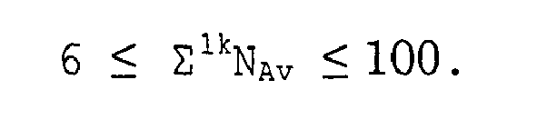
- The method of manufacturing a toner according to any one of Claims 1 to 3, wherein, when the volume of the slurry and the mixture filling the accumulation portion of the pth tandemly arranged continuous emulsification unit is represented by pV (kg) and K is an integer of 2 or more, the difference between any of the pV (Kg) in the k tandemly arranged continuous emulsification units is less than 10 (Kg).
- The method of manufacturing a toner according to any one of Claims 1 to 4, wherein, the difference between any one of circumference speed of the emulsification stirring blades provided in the k tandemly arranged continuous emulsification units is from 0 to 10 (m/sec).
- The method of manufacturing a toner according to any one of Claims 1 to 5, wherein, the circumference speed of any blade in the k tandemly arranged continuous smulsification units is from 10 to 24 (m/sec).
- The method of manufacturing a toner according to any one of Claims 1 to 6, wherein, the circulation portion in the continuous emulsification mechanism at least partially has a loop form.
- The method of manufacturing a toner according to any one of Claims 1 to 7, wherein, the emulsification is performed by a pipeline homomixer.
- The method of manufacturing a toner according to any one of Claims 1 to 8, wherein, the circulation portion in the continuous emulsification mechanism at least partially has a stocktank form.
- The method of manufacturing a toner according to any one of Claims 1 to 9, wherein the toner has a volume average particle diameter (Dv) of from 3 to 10 µm.
- The method of manufacturing a toner according to any one of Claims 1 to 10, wherein the value (Dv/Dn) obtained by dividing the volume average particle diameter (Dv) with the number average particle diameter (Dn) is from 1.05 to 1.25.
- A developer of developing electrostatic images comprising a toner and a carrier,
wherein the toner is manufactured by the method of any one of Claims 1 to 11. - An image forming method, comprising:forming a latent electrostatic image on an image bearing member;visualizing the latent electrostatic image with the toner manufactured by the method of manufacturing a toner of any one of Claims 1 to 11 or the developer of Claim 12;transferring the visualized image to a recording material; andfixing the visualized image.
- An image forming apparatus, comprising:an image bearing member;a charging device configured to charge the image bearing member;an irradiating device configured to irradiate the image bearing member to form a latent electrostatic image thereon;a developing device configured to develop the latent electrostatic image on the image bearing member with the toner manufactured by the method of manufacturing a toner of any one of Claims 1 to 11 or the developer of Claim 12;a cleaning device configured to remove residual toner remaining on the image bearing member;a transfer device configured to transfer the toner image to a recording material; anda fixing device configured to fix the toner image on the recording material.
- A process cartridge, comprising:an image bearing member;a developing device using the toner manufactured by the method of manufacturing a toner of any one of Claims 1 to 11 or the developer of Claim 12; andoptionally at least one of a charging device and a cleaning device;wherein the process cartridge is integrally and detachably attached to a main body of an image forming apparatus.
Applications Claiming Priority (1)
| Application Number | Priority Date | Filing Date | Title |
|---|---|---|---|
| JP2004264709 | 2004-09-10 |
Publications (2)
| Publication Number | Publication Date |
|---|---|
| EP1666975A1 true EP1666975A1 (en) | 2006-06-07 |
| EP1666975B1 EP1666975B1 (en) | 2018-11-07 |
Family
ID=35115921
Family Applications (1)
| Application Number | Title | Priority Date | Filing Date |
|---|---|---|---|
| EP05019566.8A Expired - Lifetime EP1666975B1 (en) | 2004-09-10 | 2005-09-08 | Method of manufacturing toner |
Country Status (1)
| Country | Link |
|---|---|
| EP (1) | EP1666975B1 (en) |
Citations (2)
| Publication number | Priority date | Publication date | Assignee | Title |
|---|---|---|---|---|
| US5264315A (en) * | 1992-04-20 | 1993-11-23 | Xerox Corporation | Process for the continuous preparation of encapsulated toner |
| JPH09311502A (en) * | 1996-03-21 | 1997-12-02 | Dainippon Ink & Chem Inc | Method for producing toner for developing electrostatic images |
-
2005
- 2005-09-08 EP EP05019566.8A patent/EP1666975B1/en not_active Expired - Lifetime
Patent Citations (2)
| Publication number | Priority date | Publication date | Assignee | Title |
|---|---|---|---|---|
| US5264315A (en) * | 1992-04-20 | 1993-11-23 | Xerox Corporation | Process for the continuous preparation of encapsulated toner |
| JPH09311502A (en) * | 1996-03-21 | 1997-12-02 | Dainippon Ink & Chem Inc | Method for producing toner for developing electrostatic images |
Also Published As
| Publication number | Publication date |
|---|---|
| EP1666975B1 (en) | 2018-11-07 |
Similar Documents
| Publication | Publication Date | Title |
|---|---|---|
| US7241548B2 (en) | Toner, method for preparing the toner, and image forming method and apparatus using the toner | |
| EP1835353B1 (en) | Toner | |
| US7294442B2 (en) | Toner for developing electrostatic image, method for manufacturing the toner, developer including the toner, container containing the toner, and color image forming method using the toner | |
| US6846604B2 (en) | Toner and image forming apparatus using the toner | |
| EP1580614B1 (en) | Toner and image forming device using the same | |
| EP1239334A1 (en) | Toner composition and method for manufacturing the toner composition | |
| US8192911B2 (en) | Method of manufacturing toner and toner | |
| US20040157146A1 (en) | Dry toner | |
| US20040131961A1 (en) | Toner, developer including the toner, and method for fixing toner image | |
| US20060172214A1 (en) | Toner, method of making, method of using | |
| US20040259013A1 (en) | Method for preparing functional particulate organic material, toner using the functional particulate organic material, and image forming method and apparatus using the toner | |
| EP1998226A1 (en) | Method of manufacturing toner and toner | |
| US20040106057A1 (en) | Toner and image forming apparatus using the toner | |
| US8492063B2 (en) | Method of manufacturing toner | |
| US8187785B2 (en) | Method of manufacturing toner | |
| US7585607B2 (en) | Method of manufacturing toner, the toner produced thereby, developer containing the toner and an image forming apparatus using the toner | |
| EP1640809B1 (en) | Toner manufacturing method, image forming method, image forming apparatus, and process cartridge | |
| EP2124106A1 (en) | Method of manufacturing a toner, apparatus of manufacturing a toner, a toner, an image forming method and an image forming apparatus | |
| EP1666975B1 (en) | Method of manufacturing toner | |
| JP4676845B2 (en) | Electrophotographic toner manufacturing apparatus, manufacturing method, and electrophotographic toner | |
| JP4037325B2 (en) | Toner for electrophotography and production method | |
| JP4657935B2 (en) | Toner for electrostatic image development | |
| JP4086240B2 (en) | Electrophotographic toner manufacturing apparatus, manufacturing method, and electrophotographic toner | |
| JP2006065197A (en) | Toner manufacturing apparatus and manufacturing method, toner, process cartridge, and image forming apparatus | |
| JP2012128446A (en) | Production method of toner, and developer, container containing toner, process cartridge, image forming apparatus and image forming method |
Legal Events
| Date | Code | Title | Description |
|---|---|---|---|
| PUAI | Public reference made under article 153(3) epc to a published international application that has entered the european phase |
Free format text: ORIGINAL CODE: 0009012 |
|
| AK | Designated contracting states |
Kind code of ref document: A1 Designated state(s): AT BE BG CH CY CZ DE DK EE ES FI FR GB GR HU IE IS IT LI LT LU LV MC NL PL PT RO SE SI SK TR |
|
| AX | Request for extension of the european patent |
Extension state: AL BA HR MK YU |
|
| 17P | Request for examination filed |
Effective date: 20061004 |
|
| AKX | Designation fees paid |
Designated state(s): DE FR GB |
|
| 17Q | First examination report despatched |
Effective date: 20091016 |
|
| GRAP | Despatch of communication of intention to grant a patent |
Free format text: ORIGINAL CODE: EPIDOSNIGR1 |
|
| INTG | Intention to grant announced |
Effective date: 20180323 |
|
| RIN1 | Information on inventor provided before grant (corrected) |
Inventor name: KADOTA, TAKAHIRO, RICOH COMPANY, LTD Inventor name: TAKAHASHI, HIROSHI, RICOH COMPANY, LTD Inventor name: KOHZU, OSAMU, RICOH COMPANY, LTD |
|
| GRAS | Grant fee paid |
Free format text: ORIGINAL CODE: EPIDOSNIGR3 |
|
| GRAA | (expected) grant |
Free format text: ORIGINAL CODE: 0009210 |
|
| AK | Designated contracting states |
Kind code of ref document: B1 Designated state(s): DE FR GB |
|
| REG | Reference to a national code |
Ref country code: GB Ref legal event code: FG4D |
|
| REG | Reference to a national code |
Ref country code: DE Ref legal event code: R096 Ref document number: 602005054931 Country of ref document: DE |
|
| REG | Reference to a national code |
Ref country code: DE Ref legal event code: R097 Ref document number: 602005054931 Country of ref document: DE |
|
| PLBE | No opposition filed within time limit |
Free format text: ORIGINAL CODE: 0009261 |
|
| STAA | Information on the status of an ep patent application or granted ep patent |
Free format text: STATUS: NO OPPOSITION FILED WITHIN TIME LIMIT |
|
| 26N | No opposition filed |
Effective date: 20190808 |
|
| P01 | Opt-out of the competence of the unified patent court (upc) registered |
Effective date: 20230522 |
|
| PGFP | Annual fee paid to national office [announced via postgrant information from national office to epo] |
Ref country code: DE Payment date: 20240918 Year of fee payment: 20 |
|
| PGFP | Annual fee paid to national office [announced via postgrant information from national office to epo] |
Ref country code: GB Payment date: 20240919 Year of fee payment: 20 |
|
| PGFP | Annual fee paid to national office [announced via postgrant information from national office to epo] |
Ref country code: FR Payment date: 20240924 Year of fee payment: 20 |
|
| REG | Reference to a national code |
Ref country code: DE Ref legal event code: R071 Ref document number: 602005054931 Country of ref document: DE |
|
| REG | Reference to a national code |
Ref country code: GB Ref legal event code: PE20 Expiry date: 20250907 |