EP1666857A1 - Spectroscopic device - Google Patents
Spectroscopic device Download PDFInfo
- Publication number
- EP1666857A1 EP1666857A1 EP04773004A EP04773004A EP1666857A1 EP 1666857 A1 EP1666857 A1 EP 1666857A1 EP 04773004 A EP04773004 A EP 04773004A EP 04773004 A EP04773004 A EP 04773004A EP 1666857 A1 EP1666857 A1 EP 1666857A1
- Authority
- EP
- European Patent Office
- Prior art keywords
- light
- dichroic mirror
- wavelength
- dichroic
- mirror
- Prior art date
- Legal status (The legal status is an assumption and is not a legal conclusion. Google has not performed a legal analysis and makes no representation as to the accuracy of the status listed.)
- Granted
Links
Images



Classifications
-
- G—PHYSICS
- G01—MEASURING; TESTING
- G01J—MEASUREMENT OF INTENSITY, VELOCITY, SPECTRAL CONTENT, POLARISATION, PHASE OR PULSE CHARACTERISTICS OF INFRARED, VISIBLE OR ULTRAVIOLET LIGHT; COLORIMETRY; RADIATION PYROMETRY
- G01J3/00—Spectrometry; Spectrophotometry; Monochromators; Measuring colours
- G01J3/02—Details
-
- G—PHYSICS
- G01—MEASURING; TESTING
- G01J—MEASUREMENT OF INTENSITY, VELOCITY, SPECTRAL CONTENT, POLARISATION, PHASE OR PULSE CHARACTERISTICS OF INFRARED, VISIBLE OR ULTRAVIOLET LIGHT; COLORIMETRY; RADIATION PYROMETRY
- G01J3/00—Spectrometry; Spectrophotometry; Monochromators; Measuring colours
- G01J3/02—Details
- G01J3/0205—Optical elements not provided otherwise, e.g. optical manifolds, diffusers, windows
- G01J3/021—Optical elements not provided otherwise, e.g. optical manifolds, diffusers, windows using plane or convex mirrors, parallel phase plates, or particular reflectors
-
- G—PHYSICS
- G01—MEASURING; TESTING
- G01J—MEASUREMENT OF INTENSITY, VELOCITY, SPECTRAL CONTENT, POLARISATION, PHASE OR PULSE CHARACTERISTICS OF INFRARED, VISIBLE OR ULTRAVIOLET LIGHT; COLORIMETRY; RADIATION PYROMETRY
- G01J3/00—Spectrometry; Spectrophotometry; Monochromators; Measuring colours
- G01J3/02—Details
- G01J3/0256—Compact construction
-
- G—PHYSICS
- G01—MEASURING; TESTING
- G01J—MEASUREMENT OF INTENSITY, VELOCITY, SPECTRAL CONTENT, POLARISATION, PHASE OR PULSE CHARACTERISTICS OF INFRARED, VISIBLE OR ULTRAVIOLET LIGHT; COLORIMETRY; RADIATION PYROMETRY
- G01J3/00—Spectrometry; Spectrophotometry; Monochromators; Measuring colours
- G01J3/28—Investigating the spectrum
- G01J3/30—Measuring the intensity of spectral lines directly on the spectrum itself
- G01J3/36—Investigating two or more bands of a spectrum by separate detectors
Definitions
- the present invention relates to a spectroscopic device for spectroscopically separating detected light into light of different wavelength ranges and detecting light of each wavelength range by a photodetector.
- Patent Document 1 discloses an example of this type of conventional spectroscopic device.
- a plurality of dichroic mirrors which are different in rising wavelength of reflectivity are arranged in increasing or decreasing order of the wavelength to thereby construct a dichroic mirror array.
- a planar mirror is disposed at the light reflection side of the dichroic mirror array so as to oppose the dichroic mirror array.
- a light-receiving element array having a plurality of light-receiving elements arranged along the arrangement direction of the dichroic mirrors is disposed at the light transmission side of the dichroic mirror array.
- each dichroic mirror In the spectroscopic device described above, light transmitted through each dichroic mirror is obliquely made incident to the light-receiving face of each light-receiving element, and thus there is a risk that cross-talk occurs between adjacent light-receiving elements.
- the present invention has been implemented under such circumstances, and has an object to provide a spectroscopic device that can suppress the occurrence of cross-talk when light beams having different wavelength ranges are detected.
- a spectroscopic device for spectroscopically separating detected light into light beams having different wavelength ranges and optically receiving light of each wavelength range by a light-receiving face of a photodetector is characterized by including a dichroic mirror array having a plurality of dichroic mirrors in which the long wavelength range sides thereof are light transmissible ranges and the shortest wavelengths of the light transmissible ranges are different from each other, and that are arranged along an oblique direction of a plane opposing a light-receiving face at a predetermined inclination angle to the light-receiving face in a decreasing order of the shortest wavelength so as to be substantially parallel to the plane, and a reflection member that is disposed at the light reflection side of the dichroic mirror array and equipped with a reflection face opposing the dichroic mirrors substantially parallel to the dichroic mirrors, wherein the plane is inclined so that the dichroic mirror side having the minimum shortest wavelength
- the detected light is made incident along the perpendicular direction of the light-receiving face of the photodetector to the dichroic mirror having the maximum shortest wavelength of the light transmissible range, and thus the light transmitted through the dichroic mirror is made incident substantially perpendicular to the light-receiving face.
- the light reflected from the dichroic mirror is reflected by the reflection face of the reflecting member disposed at the light reflection side of the dichroic mirror array.
- each dichroic mirror is disposed substantially parallel to the plane that is inclined so that the dichroic mirror side having the minimum shortest wavelength is nearer to the light-receiving face than the dichroic mirror side having the maximum shortest wavelength, and it opposes the reflection face of the reflecting member substantially parallel to the reflection face. Therefore, the light reflected from the reflection face is made incident to a dichroic mirror having the second maximum shortest wavelength of the light transmissible range along the perpendicular direction of the light-receiving face. Therefore, the light transmitted through the dichroic mirror having the second maximum shortest wavelength is also made incident substantially perpendicular to the light-receiving face.
- the light reflection and transmission is repeated until the light having the shortest wavelength of the light transmissible range reaches the minimum dichroic mirror, and all the light beams transmitted through the respective dichroic mirrors (the light beams different in wavelength range) are made incident substantially perpendicular to the light-receiving face of the photodetector. Accordingly, occurrence of cross-talk in the photodetector can be suppressed when the light beams having different wavelength ranges are optically received.
- the spectroscopic device for spectroscopically separating detected light into light beams having different wavelength ranges and optically receiving light of each wavelength range by a light-receiving face of a photodetector, is characterized by including a dichroic mirror array having a plurality of dichroic mirrors in which the short wavelength range sides thereof are light transmissible ranges and the longest wavelengths of the light transmissible ranges are different from each other, and that are arranged along an oblique direction of a plane opposing a light-receiving face at a predetermined inclination angle to the light-receiving face in an increasing order of the longest wavelength so as to be substantially parallel to the plane and a reflection member that is disposed at the light reflection side of the dichroic mirror array and equipped with a reflection face opposing the dichroic mirrors substantially parallel to the dichroic mirrors, wherein the plane is inclined so that the dichroic mirror side having the maximum longest wavelength is nearer to the light-receiving
- This spectroscopic device is different from the spectroscopic device using the dichroic mirrors whose long wavelength range side is a light transmissible range in that the spectroscopic device uses dichroic mirrors whose short wavelength range side is a light transmissible range. Accordingly, in the spectroscopic device, a plurality of dichroic mirrors which are different in the longest wavelength of the light transmissible range from one another are arranged in an increasing order of the longest wavelength, whereby the occurrence of cross-talk in the photodetector can be suppressed when light beams of different wavelength ranges are optically received as in the case of the above-described spectroscopic device.
- a band pass filter is disposed at the position corresponding to each of the dichroic mirrors in the perpendicular direction of the photoelectric surface between the photoelectric surface and the dichroic mirror array. Accordingly, the light transmitted through each dichroic mirror is also transmitted through the band pass filter, and thus wavelength discrimination can be enhanced. Accordingly, it is possible to enhance the resolution when the detected light is spectroscopically separated. In addition, the light transmitted through each dichroic mirror is made incident substantially perpendicular to the band pass filter, so that the wavelength area of the light transmitted through the band pass filter can be prevented from being shifted.
- the photodetector is a linear multi-anode type photomultiplier tube. Accordingly, the light of each wavelength range which is spectroscopically separated can be detected with high accuracy.
- occurrence of cross-talk can be suppressed when light beams having different wavelength ranges are optically received.
- FIG 1 is a cross-sectional view showing a first embodiment of a spectroscopic device according to the present invention.
- 1 spectroscopic device
- 2 photomultiplier tube (photodetector)
- 7 photoelectric surface (light-receiving face)
- 21 dichroic mirror array
- 23 reflecting member
- 23a main mirror surface (reflection face)
- 24 band pass filter
- DM n dichroic mirror
- p plane
- a spectroscopic device 1 is equipped with a linear multi-anode type photomultiplier tube (photodetector) 2.
- This photomultiplier tube 2 has a quadratic prism type metal side tube 3, and a rectangular light incident plate 4 formed of a light transmissible material such as glass is air-tightly fixed to the opening portion at one end side of the side tube 3 by fusion bonding or the like.
- the light incident plate 4 is partitioned at equal intervals by a plurality of light shielding plates 6 provided so as to extend in the perpendicular direction to the sheet surface (hereinafter referred to as "width direction") in FIG 2, whereby a plurality of light incident portions 4a extending in the width direction are formed in the light incident plate 4. Furthermore, a photoelectric surface (light-receiving face) 7 is formed on the inner surface of the light incident plate 4.
- a rectangular stem 8 formed of an insulating material such as glass is attached to the opening portion at the other end side of the side tube 3. More specifically, a metal surrounding member 9 for surrounding the side surface of the stem 8 is air-tightly fixed to the stem 8 by fusion bonding or the like, and a flange 9a formed at one end of the surrounding member 9 and a flange portion 3a formed at the other end of the side tube 3 are air-tightly joined to each other by resistance welding or the like.
- a metal channel dynode 12 having multilayered dynodes 11 is disposed in a vacuum space S formed by the side tube 3, the light incident plate 4, the stem 8, etc. Furthermore, a flat plate type converging electrode 13 is disposed between the metal channel dynode 12 and the photoelectric surface 7 in the vacuum space S. A plurality of slits 13a extending in the width direction are formed, and each slit 13a is opposed to each light incident portion 4a of the light incident plate 4 in the perpendicular direction to the photoelectric surface 7.
- a plurality of multi-anodes 14 extending in the width direction are linearly arranged between the metal channel dynode 12 and the stem 8 in the vacuum space S, and each multi-anode 14 is opposed to each light incident portion 4a of the light incident plate 4 in the perpendicular direction to the photoelectric surface 7.
- a partition wall 16 for insulating the adjacent multi-anodes 14, 14 from each other is erectly provided on the inner surface of the stem 8, and the occurrence of cross-talk is suppressed.
- one end of a stem pin 17 for taking out an output signal is connected to each multi-anode 14, and the other end of each stem pin 17 air-tightly penetrates through the stem 8 and projects outwardly.
- the photoelectron multiplying action will be described by focusing on one channel C m .
- light transmitted through the light incident portion 4a is irradiated to the photoelectric surface 7, electrons in the photoelectric surface 7 are excited, and photoelectrons are discharged into the vacuum space S.
- the discharged photoelectrons are passed through the slit 13 a of the convergent electrode 13 and converged to the dynode 11 at the foremost stage.
- the photoelectrons are multiplied by the metal channel dynode 12 while passing through the electron passage hole located between the light incident portion 4a and the multi-anode 14, and a secondary electron group is discharged from the dynode 12 at the last stage.
- This secondary electron group reaches the multi-anode 14 and an output signal is transmitted through the stem pin 17 connected to the multi-anode 14.
- each dichroic mirror is a light transmissible range, and the shortest wavelengths of the light transmissible ranges of the respective dichroic mirrors are different from one another.
- the dichroic mirrors are arranged in a decreasing order of the shortest wavelength along the inclination direction of the plane P.
- Each dichroic mirror DM n extends in the direction vertical to the sheet surface (hereinafter referred to as "width direction") in FIG 3, and it opposes each light incident portion 4a in the perpendicular direction to the photoelectric surface 7.
- the distance between the dichroic mirror DM 1 having the maximum shortest wavelength and the photoelectric surface 7 is larger than the distance between the minimum shortest wave wavelength and the photoelectric surface 7.
- the shortest wavelength of the light transmissible range when the long wavelength range side is a light transmissible range means the wavelength ⁇ n when the light transmission in each dichroic mirror DM n is equal to 50% as shown in FIG 4. It is assumed in the dichroic mirror array 21 that the shortest wavelength ⁇ n of the light transmissible range is gradually increased in the order of the dichroic mirrors DM 8 , DM 7 , DM 6 , ..., DM 1 .
- a block type glass reflecting member 23 is disposed at the light reflection side of the dichroic mirror array 21.
- the reflection member 23 is provided with a main mirror surface (reflection face) 23a opposing the dichroic mirror array 21 substantially parallel to the dichroic mirror array 21, and a light guiding mirror surface 23b which is inclined at an angle of 45 degrees with respect to the photoelectric surface 7 and opposes the dichroic mirror DM 1 in the perpendicular direction of the photoelectric surface 7.
- a band pass filter 24 extending in the width direction is disposed at the position corresponding to each dichroic mirror DM n in the perpendicular direction of the photoelectric surface 7 between the photoelectric surface 7 and the dichroic mirror array 21.
- Each band pass filter 24 is fixed to the outer surface of the light incident plate 4, and the adjacent band pass filters 24, 24 are partitioned by a light shielding plate 26 extending in the width direction.
- a light passage R is formed between the corresponding dichroic mirror DM n and band pass filter 24 in the perpendicular direction of the photoelectric surface 7, and the adjacent light passages R, R are partitioned by a light shielding member 27 extending in the width direction.
- the detected light which has been wave-shaped into collimated light is made incident to the light guiding mirror surface 23b of the reflecting member 23 parallel to the photoelectric surface 7 and along the arrangement direction of the light incident portion 4a.
- the light guiding mirror surface 23b is inclined at an angle of 45 degrees with respect to the photoelectric surface 7 and opposed the photoelectric surface 7 in the perpendicular direction of the photoelectric surface 7. Therefore, the detected light is reflected from the light guiding surface 23b so as to be bent by 90 degrees, and made incident to the dichroic mirror DM 1 along the perpendicular direction of the photoelectric surface 7. Therefore, the light transmitted through the dichroic mirror DM 1 (mainly, light of a longer wavelength range than the wavelength ⁇ 1 ) is transmitted through the band pass filter 24 and the light incident portion 4a, and then made incident substantially perpendicular to the photoelectric surface 7.
- the light reflected from the dichroic mirror DM 1 (mainly, light of a shorter wavelength range than the wavelength ⁇ 1 ) is reflected from the main mirror surface 23a of the reflecting member 23.
- the dichroic mirror array 21 is inclined so that the dichroic mirror DM 8 side having the minimum shortest wavelength is nearer to the photoelectric surface 7 than the dichroic mirror DM 1 side having the maximum shortest wavelength, and also it opposes the main mirror surface 23a substantially parallel to the main mirror surface 23a. Therefore, the light reflected from the main mirror surface 23a is made incident to the second largest shortest wavelength of the light transmissible range along the perpendicular direction of the photoelectric surface 7.
- the light transmitted through the dichroic mirror DM 2 (mainly, light whose wavelength range is shorter than the wavelength ⁇ 1 and longer than the wavelength ⁇ 2 ) is also transmitted through the band pass filter 24 and the light incident portion 4a and made incident substantially perpendicular to the photoelectric surface 7.
- the light reflection and transmission is repeated until the light reaches the dichroic mirror DM 8 having the minimum shortest wavelength of the light transmissible range, and all the light beams transmitted through the respective dichroic mirrors DM n (light beams which are different in wavelength range from one another) are transmitted through the band pass filter 24 and the light incident portion 4a and made incident substantially perpendicular to the photoelectric surface 7. Accordingly, occurrence of cross-talk in the photomultiplier tube 2 can be suppressed when light beams having different wavelength ranges are optically received, so that the output signal of each channel C m can be taken out with high accuracy.
- each dichroic mirror DM n is disposed on the plane P which is inclined at an inclination angle ⁇ of 12 degrees with respect to the photoelectric surface 7, and light is made incident to each dichroic mirror DM n along the perpendicular direction of the photoelectric surface 7, so that the incident angle of the light to each dichroic mirror DM n is equal to 12 degrees.
- the spectroscopic device 1 has high wavelength discrimination of each dichroic mirror DM n . From this point of view, it is preferable that the inclination angle ⁇ is equal to 15 degrees or less.
- the spectroscopic device 1 can be further miniaturized as compared with a spectroscopic device in which each dichroic mirror DM n is disposed to be inclined at 45 degrees with respect to the photoelectric surface 7.
- each diachronic mirror DM n is passed through the band pass filter 24, and thus the wavelength discrimination can be further enhanced. Accordingly, the resolution when the detected light is spectroscopically separated can be enhanced.
- the light transmitted through each dichroic mirror DM n is made incident substantially perpendicular to the band pass filter 24, so that the wavelength range of the light transmitted through the band pass filter 24 can be prevented from being shifted.
- a spectroscopic device 1 according to a second embodiment is different from the spectroscopic device 1 of the first embodiment in the constructions of the dichroic mirror array 21 and the reflecting member 23. Accordingly, the constructions of the dichroic mirror array 21 and the reflecting member 23 will be mainly described, and description of other constructions will be omitted.
- the spectroscopic device 1 has a dichroic mirror array 21 disposed at the light incident side of the light incident plate 4 of the photomultiplier tube 2.
- Each dichroic mirror DM n extends in the perpendicular direction to the sheet surface (hereinafter referred to as "width direction"), and opposes each light incident portion 4a in the perpendicular direction of the photoelectric surface 7.
- the plane P is inclined so that the dichroic mirror DM 8 having the minimum shortest wavelength is nearer to the photoelectric surface as compared with the dichroic mirror DM 1 side having the maximum shortest wavelength.
- a block-shaped glass reflecting member 23 is disposed at the light reflection side of the dichroic mirror array 21.
- the reflection member 23 is provided with a main mirror surface (reflection face) 23a opposing each dichroic mirror DM n substantially parallel, and a light guiding mirror surface 23b which is inclined at an angle of 45 degrees with respect to the photoelectric surface 7 and opposes the dichroic mirror DM 1 in the perpendicular direction of the photoelectric surface 7.
- the spectroscopic action of the detected light in the spectroscopic device 1 of the second embodiment that is constructed by the dichroic mirror array 21 and the reflecting member 23 as described above will be described.
- the detected light which has been wave-shaped into collimated light is made incident to the light guiding mirror surface 23b of the reflecting member 23 parallel to the photoelectric surface 7 and along the arrangement direction of the light incident portion 4a.
- the light guiding mirror surface 23b is inclined at an angle of 45 degrees with respect to the photoelectric surface 7 and also opposes the dichroic mirror DM 1 in the perpendicular direction of the photoelectric surface 7.
- the detected light is reflected by the light guiding surface 23b so as to be bent by 90 degrees, and made incident to the dichroic mirror DM 1 along the perpendicular direction of the photoelectric surface 7. Therefore, the light transmitted through the dichroic mirror DM 1 (mainly, light of a longer wavelength range than the wavelength ⁇ 1 ) is transmitted through the band pass filter 24 and the light incident portion 4a and made incident substantially perpendicular to the photoelectric surface 7.
- each dichroic mirror DM n is disposed substantially parallel to the plane P which is inclined so that the dichroic mirror DM 8 side having the minimum shortest wavelength is nearer to the light-receiving face than the dichroic mirror DM 1 side having the maximum shortest wavelength, and also it opposes each main mirror surface 23a of the reflecting member 23 substantially parallel.
- the light reflected from the main mirror surface 23a is made incident to the dichroic mirror DM 2 having the second largest shortest wavelength of the light transmissible range along the perpendicular direction of the photoelectric surface 7. Therefore, the light transmitted through the dichroic mirror DM 2 (mainly, light whose wavelength range is shorter than the wavelength ⁇ 1 and also longer than the wavelength ⁇ 2 ) is also transmitted through the band pass filter 24 and the light incident portion 4a and made incident substantially perpendicular to the photoelectric surface 7.
- the light reflection and transmission is repeated until the light reaches the dichroic mirror DM 8 having the minimum shortest wavelength of the light transmissible range, and all the light beams transmitted through each dichroic mirror DM n (light beams which are different in wavelength range from one another) are transmitted through the band pass filter 24 and the light incident portion 4a and made incident substantially perpendicular to the photoelectric surface 7. Accordingly, when the light beams of different wavelength ranges are optically received, occurrence of cross-talk in the photomultiplier tube 2 can be suppressed, and the output signal of each channel C m can be taken out with high accuracy.
- the distance between each dichroic mirror DM n and the photoelectric surface 7 is shorter than that in the spectroscopic device 1 of the first embodiment, and thus the optical path length of light transmitted through each dichroic mirror DM n is shorter. Accordingly, as compared with the spectroscopic device 1 of the first embodiment, the light scattering between each dichroic mirror DM n and the photoelectric surface 7 can be suppressed, and a reduction in cross-talk can be further promoted. In addition, as compared with the spectroscopic device 1 of the first embodiment, the distance between each dichroic mirror DM n and the photoelectric surface 7 is shorter, and thus the miniaturization of the spectroscopic device 1 can be further promoted.
- the present invention is not limited to the above embodiments.
- a plurality of dichroic mirrors DM n whose short wavelength range side is the light transmissible range and whose longest wavelengths of the light transmissible ranges are different from one another may be arranged in an increasing order of the longest wavelength on a plane P which is inclined at an inclination angle ⁇ with respect to the photoelectric surface 7 and opposes the photoelectric surface 7.
- the distance between the dichroic mirror DM 1 having the minimum longest wavelength and the photoelectric surface 7 is set to be larger than the distance between the dichroic mirror DM 8 having the maximum shortest wavelength and the photoelectric surface 7.
- the longest wavelength of the light transmissible range when the short wavelength range side is a light transmissible range means the wavelength ⁇ n when the light transmission in each dichroic mirror DM n is equal to 50%.
- the longest wavelength ⁇ n of the light transmissible range is gradually increased in the order of the dichroic mirror DM 1 , DM 2 , DM 3 , .., DM 8 .
- the spectroscopic device 1 of this case is different from the spectroscopic device 1 of the above embodiment using the dichroic mirror DM n whose long wavelength range side is a light transmissible range.
- a plurality of dichroic mirrors DM n whose long wavelengths of the light transmissible ranges are different from one another are arranged in an increasing order of the longest wavelength, whereby the occurrence of cross-talk in the photomultiplier tube 2 can be suppressed when light beams of different wavelength ranges are optically received as in the case of the spectroscopic device 1 of the above embodiment.
- the linear multi-anode type photomultiplier tube 2 is used as the photodetector in order to detect each spectroscopically separated wavelength range light with high accuracy, however, a photodiode array, a linear CCD or the like may be used as the photodetector.
Landscapes
- Physics & Mathematics (AREA)
- Spectroscopy & Molecular Physics (AREA)
- General Physics & Mathematics (AREA)
- Spectrometry And Color Measurement (AREA)
Abstract
Description
- The present invention relates to a spectroscopic device for spectroscopically separating detected light into light of different wavelength ranges and detecting light of each wavelength range by a photodetector.
- The
following Patent Document 1 discloses an example of this type of conventional spectroscopic device. In this spectroscopic device, a plurality of dichroic mirrors which are different in rising wavelength of reflectivity are arranged in increasing or decreasing order of the wavelength to thereby construct a dichroic mirror array. A planar mirror is disposed at the light reflection side of the dichroic mirror array so as to oppose the dichroic mirror array. Furthermore, a light-receiving element array having a plurality of light-receiving elements arranged along the arrangement direction of the dichroic mirrors is disposed at the light transmission side of the dichroic mirror array. - When collimated light is obliquely made incident from the planar mirror side to a dichroic mirror located at one end in the thus constructed spectroscopic device, light having wavelengths longer than the rising wavelength of the reflectivity of the dichroic mirror is reflected from the diachronic mirror, and light having wavelengths shorter than the rising wavelength is transmitted through the diachronic mirror. The reflected light is reflected from the planar mirror and made incident to the adjacent dichroic mirror. Subsequently, the light reflection and transmission is repeated until the light reaches the dichroic mirror located at the other end. As described above, light beams having different wavelength ranges are, respectively, transmitted through the respective dichroic mirrors, so that the collimated light is spectroscopically separated. The light transmitted through each dichroic mirror is optically received by the light-receiving elements arranged along the arrangement direction of the dichroic mirrors.
Patent Document 1: Japanese Published Unexamined Patent Application No. H10-62246 - However, in the spectroscopic device described above, light transmitted through each dichroic mirror is obliquely made incident to the light-receiving face of each light-receiving element, and thus there is a risk that cross-talk occurs between adjacent light-receiving elements.
- Therefore, the present invention has been implemented under such circumstances, and has an object to provide a spectroscopic device that can suppress the occurrence of cross-talk when light beams having different wavelength ranges are detected.
- In order to attain the above object, a spectroscopic device according to the present invention for spectroscopically separating detected light into light beams having different wavelength ranges and optically receiving light of each wavelength range by a light-receiving face of a photodetector is characterized by including a dichroic mirror array having a plurality of dichroic mirrors in which the long wavelength range sides thereof are light transmissible ranges and the shortest wavelengths of the light transmissible ranges are different from each other, and that are arranged along an oblique direction of a plane opposing a light-receiving face at a predetermined inclination angle to the light-receiving face in a decreasing order of the shortest wavelength so as to be substantially parallel to the plane, and a reflection member that is disposed at the light reflection side of the dichroic mirror array and equipped with a reflection face opposing the dichroic mirrors substantially parallel to the dichroic mirrors, wherein the plane is inclined so that the dichroic mirror side having the minimum shortest wavelength is nearer to the light-receiving face than the dichroic mirror side having the maximum shortest wavelength, the detected light is made incident to the dichroic mirror having the maximum shortest wavelength along the perpendicular direction of the light-receiving face.
- In this spectroscopic device, the detected light is made incident along the perpendicular direction of the light-receiving face of the photodetector to the dichroic mirror having the maximum shortest wavelength of the light transmissible range, and thus the light transmitted through the dichroic mirror is made incident substantially perpendicular to the light-receiving face. On the other hand, the light reflected from the dichroic mirror is reflected by the reflection face of the reflecting member disposed at the light reflection side of the dichroic mirror array. At this time, each dichroic mirror is disposed substantially parallel to the plane that is inclined so that the dichroic mirror side having the minimum shortest wavelength is nearer to the light-receiving face than the dichroic mirror side having the maximum shortest wavelength, and it opposes the reflection face of the reflecting member substantially parallel to the reflection face. Therefore, the light reflected from the reflection face is made incident to a dichroic mirror having the second maximum shortest wavelength of the light transmissible range along the perpendicular direction of the light-receiving face. Therefore, the light transmitted through the dichroic mirror having the second maximum shortest wavelength is also made incident substantially perpendicular to the light-receiving face. As described above, the light reflection and transmission is repeated until the light having the shortest wavelength of the light transmissible range reaches the minimum dichroic mirror, and all the light beams transmitted through the respective dichroic mirrors (the light beams different in wavelength range) are made incident substantially perpendicular to the light-receiving face of the photodetector. Accordingly, occurrence of cross-talk in the photodetector can be suppressed when the light beams having different wavelength ranges are optically received.
- Also, the spectroscopic device according to the present invention for spectroscopically separating detected light into light beams having different wavelength ranges and optically receiving light of each wavelength range by a light-receiving face of a photodetector, is characterized by including a dichroic mirror array having a plurality of dichroic mirrors in which the short wavelength range sides thereof are light transmissible ranges and the longest wavelengths of the light transmissible ranges are different from each other, and that are arranged along an oblique direction of a plane opposing a light-receiving face at a predetermined inclination angle to the light-receiving face in an increasing order of the longest wavelength so as to be substantially parallel to the plane and a reflection member that is disposed at the light reflection side of the dichroic mirror array and equipped with a reflection face opposing the dichroic mirrors substantially parallel to the dichroic mirrors, wherein the plane is inclined so that the dichroic mirror side having the maximum longest wavelength is nearer to the light-receiving face than the dichroic mirror side having the minimum longest wavelength, the detected light is made incident to the dichroic mirror having the minimum longest wavelength along the perpendicular direction of the light-receiving face.
- This spectroscopic device is different from the spectroscopic device using the dichroic mirrors whose long wavelength range side is a light transmissible range in that the spectroscopic device uses dichroic mirrors whose short wavelength range side is a light transmissible range. Accordingly, in the spectroscopic device, a plurality of dichroic mirrors which are different in the longest wavelength of the light transmissible range from one another are arranged in an increasing order of the longest wavelength, whereby the occurrence of cross-talk in the photodetector can be suppressed when light beams of different wavelength ranges are optically received as in the case of the above-described spectroscopic device.
- It is preferable that a band pass filter is disposed at the position corresponding to each of the dichroic mirrors in the perpendicular direction of the photoelectric surface between the photoelectric surface and the dichroic mirror array. Accordingly, the light transmitted through each dichroic mirror is also transmitted through the band pass filter, and thus wavelength discrimination can be enhanced. Accordingly, it is possible to enhance the resolution when the detected light is spectroscopically separated. In addition, the light transmitted through each dichroic mirror is made incident substantially perpendicular to the band pass filter, so that the wavelength area of the light transmitted through the band pass filter can be prevented from being shifted.
- It is preferable that the photodetector is a linear multi-anode type photomultiplier tube. Accordingly, the light of each wavelength range which is spectroscopically separated can be detected with high accuracy.
- According to the present invention, occurrence of cross-talk can be suppressed when light beams having different wavelength ranges are optically received.
- FIG 1 is a cross-sectional view showing a first embodiment of a spectroscopic device according to the present invention.
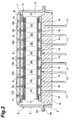
- FIG 2 is an enlarged cross-sectional view showing a photomultiplier tube of the spectroscopic device of FIG 1.
- FIG 3 is an enlarged cross-sectional view showing a dichroic mirror array peripheral portion of the spectroscopic device of FIG. 1.
- FIG 4 is a graph showing the minimum wavelength of a light transmissible range when a long wavelength range side is a light transmissible range.
- FIG 5 is a graph showing an example of a light transmission characteristic of every incident angle in the dichroic mirror.
- FIG 6 is a cross-sectional view showing a second embodiment of the spectroscopic device according to the present invention.
- FIG 7 is an enlarged cross-sectional view showing a dichroic mirror array peripheral portion of the spectroscopic device of FIG 6.
- FIG 8 is a graph showing the maximum wavelength of the light transmissible range when a short wavelength range side is a light transmissible range.
- 1: spectroscopic device, 2: photomultiplier tube (photodetector), 7: photoelectric surface (light-receiving face), 21: dichroic mirror array, 23: reflecting member, 23a: main mirror surface (reflection face), 24: band pass filter, DMn: dichroic mirror, p: plane
- Preferred embodiments according to the present invention will be described hereinafter in detail with reference to the drawings. In the description of the drawings, the same or corresponding parts are represented by the same reference numerals, and overlapping description is omitted.
- [First Embodiment]
As shown in FIG 1 and FIG 2, aspectroscopic device 1 is equipped with a linear multi-anode type photomultiplier tube (photodetector) 2. Thisphotomultiplier tube 2 has a quadratic prism typemetal side tube 3, and a rectangularlight incident plate 4 formed of a light transmissible material such as glass is air-tightly fixed to the opening portion at one end side of theside tube 3 by fusion bonding or the like. Thelight incident plate 4 is partitioned at equal intervals by a plurality oflight shielding plates 6 provided so as to extend in the perpendicular direction to the sheet surface (hereinafter referred to as "width direction") in FIG 2, whereby a plurality oflight incident portions 4a extending in the width direction are formed in thelight incident plate 4. Furthermore, a photoelectric surface (light-receiving face) 7 is formed on the inner surface of thelight incident plate 4. - A
rectangular stem 8 formed of an insulating material such as glass is attached to the opening portion at the other end side of theside tube 3. More specifically, ametal surrounding member 9 for surrounding the side surface of thestem 8 is air-tightly fixed to thestem 8 by fusion bonding or the like, and aflange 9a formed at one end of the surroundingmember 9 and aflange portion 3a formed at the other end of theside tube 3 are air-tightly joined to each other by resistance welding or the like. - As described above, a
metal channel dynode 12 havingmultilayered dynodes 11 is disposed in a vacuum space S formed by theside tube 3, thelight incident plate 4, thestem 8, etc. Furthermore, a flat platetype converging electrode 13 is disposed between themetal channel dynode 12 and thephotoelectric surface 7 in the vacuum space S. A plurality ofslits 13a extending in the width direction are formed, and eachslit 13a is opposed to eachlight incident portion 4a of thelight incident plate 4 in the perpendicular direction to thephotoelectric surface 7. - Furthermore, a plurality of multi-anodes 14 extending in the width direction are linearly arranged between the
metal channel dynode 12 and thestem 8 in the vacuum space S, and each multi-anode 14 is opposed to eachlight incident portion 4a of thelight incident plate 4 in the perpendicular direction to thephotoelectric surface 7. Apartition wall 16 for insulating the adjacent multi-anodes 14, 14 from each other is erectly provided on the inner surface of thestem 8, and the occurrence of cross-talk is suppressed. Furthermore, one end of astem pin 17 for taking out an output signal is connected to each multi-anode 14, and the other end of eachstem pin 17 air-tightly penetrates through thestem 8 and projects outwardly. - In the thus constructed
photomultiplier tube 2, a plurality of channels Cm (in this case, m= 1 to 8) are formed by the electron passing holes of themetal channel dynode 12 and theslits 13a of theconvergent electrode 13 located between thelight incident portions 4a which are opposed to one another in the perpendicular direction of thephotoelectric surface 7 and the multi-anodes 14. Accordingly, thephotoelectric multiplier tube 1 has a plurality of linearly arranged channels Cm. - Here, the photoelectron multiplying action will be described by focusing on one channel Cm. When light transmitted through the
light incident portion 4a is irradiated to thephotoelectric surface 7, electrons in thephotoelectric surface 7 are excited, and photoelectrons are discharged into the vacuum space S. The discharged photoelectrons are passed through theslit 13 a of theconvergent electrode 13 and converged to thedynode 11 at the foremost stage. Accordingly, the photoelectrons are multiplied by themetal channel dynode 12 while passing through the electron passage hole located between thelight incident portion 4a and the multi-anode 14, and a secondary electron group is discharged from thedynode 12 at the last stage. This secondary electron group reaches the multi-anode 14 and an output signal is transmitted through thestem pin 17 connected to the multi-anode 14. - As shown in FIG 1 and FIG 3, a
dichroic mirror array 21 is disposed at the light incident side of thelight incident plate 4 of thephotomultiplier tube 2 so as to be inclined at a predetermined inclination angle θ (here, θ = 12 degrees) along the arrangement direction of thelight incident portions 4a. In thedichroic mirror array 21, a plurality of dichroic mirrors DMn (in this case, n = 1 to 8) are arranged on a plane P which opposes thephotoelectric surface 7 at an inclination angle θ to thephotoelectric surface 7 along the inclination direction of the plane P. The long wavelength range side of each dichroic mirror is a light transmissible range, and the shortest wavelengths of the light transmissible ranges of the respective dichroic mirrors are different from one another. The dichroic mirrors are arranged in a decreasing order of the shortest wavelength along the inclination direction of the plane P. Each dichroic mirror DMn extends in the direction vertical to the sheet surface (hereinafter referred to as "width direction") in FIG 3, and it opposes eachlight incident portion 4a in the perpendicular direction to thephotoelectric surface 7. The distance between the dichroic mirror DM1 having the maximum shortest wavelength and thephotoelectric surface 7 is larger than the distance between the minimum shortest wave wavelength and thephotoelectric surface 7. - Here, the shortest wavelength of the light transmissible range when the long wavelength range side is a light transmissible range means the wavelength αn when the light transmission in each dichroic mirror DMn is equal to 50% as shown in FIG 4. It is assumed in the
dichroic mirror array 21 that the shortest wavelength αn of the light transmissible range is gradually increased in the order of the dichroic mirrors DM8, DM7, DM6, ..., DM1. - Furthermore, as shown in FIG 1 and FIG 3, a block type
glass reflecting member 23 is disposed at the light reflection side of thedichroic mirror array 21. Thereflection member 23 is provided with a main mirror surface (reflection face) 23a opposing thedichroic mirror array 21 substantially parallel to thedichroic mirror array 21, and a lightguiding mirror surface 23b which is inclined at an angle of 45 degrees with respect to thephotoelectric surface 7 and opposes the dichroic mirror DM1 in the perpendicular direction of thephotoelectric surface 7. - A
band pass filter 24 extending in the width direction is disposed at the position corresponding to each dichroic mirror DMn in the perpendicular direction of thephotoelectric surface 7 between thephotoelectric surface 7 and thedichroic mirror array 21. Eachband pass filter 24 is fixed to the outer surface of thelight incident plate 4, and the adjacent band pass filters 24, 24 are partitioned by alight shielding plate 26 extending in the width direction. A light passage R is formed between the corresponding dichroic mirror DMn andband pass filter 24 in the perpendicular direction of thephotoelectric surface 7, and the adjacent light passages R, R are partitioned by alight shielding member 27 extending in the width direction. - The spectroscopic action of the detected light in the thus constructed
spectroscopic device 1 will be described. As shown in FIG 1, the detected light which has been wave-shaped into collimated light is made incident to the light guidingmirror surface 23b of the reflectingmember 23 parallel to thephotoelectric surface 7 and along the arrangement direction of thelight incident portion 4a. The lightguiding mirror surface 23b is inclined at an angle of 45 degrees with respect to thephotoelectric surface 7 and opposed thephotoelectric surface 7 in the perpendicular direction of thephotoelectric surface 7. Therefore, the detected light is reflected from thelight guiding surface 23b so as to be bent by 90 degrees, and made incident to the dichroic mirror DM1 along the perpendicular direction of thephotoelectric surface 7. Therefore, the light transmitted through the dichroic mirror DM1 (mainly, light of a longer wavelength range than the wavelength α1) is transmitted through theband pass filter 24 and thelight incident portion 4a, and then made incident substantially perpendicular to thephotoelectric surface 7. - On the other hand, the light reflected from the dichroic mirror DM1 (mainly, light of a shorter wavelength range than the wavelength α1) is reflected from the
main mirror surface 23a of the reflectingmember 23. At this time, thedichroic mirror array 21 is inclined so that the dichroic mirror DM8 side having the minimum shortest wavelength is nearer to thephotoelectric surface 7 than the dichroic mirror DM1 side having the maximum shortest wavelength, and also it opposes themain mirror surface 23a substantially parallel to themain mirror surface 23a. Therefore, the light reflected from themain mirror surface 23a is made incident to the second largest shortest wavelength of the light transmissible range along the perpendicular direction of thephotoelectric surface 7. Therefore, the light transmitted through the dichroic mirror DM2 (mainly, light whose wavelength range is shorter than the wavelength α1 and longer than the wavelength α2) is also transmitted through theband pass filter 24 and thelight incident portion 4a and made incident substantially perpendicular to thephotoelectric surface 7. - As described above, the light reflection and transmission is repeated until the light reaches the dichroic mirror DM8 having the minimum shortest wavelength of the light transmissible range, and all the light beams transmitted through the respective dichroic mirrors DMn (light beams which are different in wavelength range from one another) are transmitted through the
band pass filter 24 and thelight incident portion 4a and made incident substantially perpendicular to thephotoelectric surface 7. Accordingly, occurrence of cross-talk in thephotomultiplier tube 2 can be suppressed when light beams having different wavelength ranges are optically received, so that the output signal of each channel Cm can be taken out with high accuracy. - It is common that light is made incident to the dichroic mirror at an incident angle of 45 degrees. However, when the incident angle is gradually reduced from 45 degrees, the rising portion of the light transmission characteristic is sharper and becomes linear as shown in FIG 5. This means that as the incident angle of light to the dichroic mirror is reduced, the wavelength discrimination is further enhanced. In the above-described
spectroscopic device 1, each dichroic mirror DMn is disposed on the plane P which is inclined at an inclination angle θ of 12 degrees with respect to thephotoelectric surface 7, and light is made incident to each dichroic mirror DMn along the perpendicular direction of thephotoelectric surface 7, so that the incident angle of the light to each dichroic mirror DMn is equal to 12 degrees. Accordingly, thespectroscopic device 1 has high wavelength discrimination of each dichroic mirror DMn. From this point of view, it is preferable that the inclination angle θ is equal to 15 degrees or less. By arranging the dichroic mirrors DMn on the plane P which is inclined at the inclination angle θ of 12 degrees with respect to thephotoelectric surface 7, thespectroscopic device 1 can be further miniaturized as compared with a spectroscopic device in which each dichroic mirror DMn is disposed to be inclined at 45 degrees with respect to thephotoelectric surface 7. - As described above, the light transmitted through each diachronic mirror DMn is passed through the
band pass filter 24, and thus the wavelength discrimination can be further enhanced. Accordingly, the resolution when the detected light is spectroscopically separated can be enhanced. In addition, the light transmitted through each dichroic mirror DMn is made incident substantially perpendicular to theband pass filter 24, so that the wavelength range of the light transmitted through theband pass filter 24 can be prevented from being shifted. - [Second Embodiment]
Aspectroscopic device 1 according to a second embodiment is different from thespectroscopic device 1 of the first embodiment in the constructions of thedichroic mirror array 21 and the reflectingmember 23. Accordingly, the constructions of thedichroic mirror array 21 and the reflectingmember 23 will be mainly described, and description of other constructions will be omitted. - As shown in FIG 6 and FIG 7, the
spectroscopic device 1 has adichroic mirror array 21 disposed at the light incident side of thelight incident plate 4 of thephotomultiplier tube 2. In thedichroic mirror array 21, a plurality of dichroic mirrors DMn (in this case, n = 1 to 8) whose long wavelength range sides are light transmissible ranges and which have the shortest wavelengths of the light transmissible ranges different from one another are arranged along an inclination direction of a plane P opposing thephotoelectric surface 7 at an inclination angle θ (in this case, θ=12 degrees) to thephotoelectric surface 7 in a decreasing order of the shortest wavelength so as to be substantially parallel to the plane P. Each dichroic mirror DMn extends in the perpendicular direction to the sheet surface (hereinafter referred to as "width direction"), and opposes eachlight incident portion 4a in the perpendicular direction of thephotoelectric surface 7. The plane P is inclined so that the dichroic mirror DM8 having the minimum shortest wavelength is nearer to the photoelectric surface as compared with the dichroic mirror DM1 side having the maximum shortest wavelength. - A block-shaped
glass reflecting member 23 is disposed at the light reflection side of thedichroic mirror array 21. Thereflection member 23 is provided with a main mirror surface (reflection face) 23a opposing each dichroic mirror DMn substantially parallel, and a lightguiding mirror surface 23b which is inclined at an angle of 45 degrees with respect to thephotoelectric surface 7 and opposes the dichroic mirror DM1 in the perpendicular direction of thephotoelectric surface 7. - As described above, the spectroscopic action of the detected light in the
spectroscopic device 1 of the second embodiment that is constructed by thedichroic mirror array 21 and the reflectingmember 23 as described above will be described. As shown in FIG 6, the detected light which has been wave-shaped into collimated light is made incident to the light guidingmirror surface 23b of the reflectingmember 23 parallel to thephotoelectric surface 7 and along the arrangement direction of thelight incident portion 4a. The lightguiding mirror surface 23b is inclined at an angle of 45 degrees with respect to thephotoelectric surface 7 and also opposes the dichroic mirror DM1 in the perpendicular direction of thephotoelectric surface 7. Therefore, the detected light is reflected by thelight guiding surface 23b so as to be bent by 90 degrees, and made incident to the dichroic mirror DM1 along the perpendicular direction of thephotoelectric surface 7. Therefore, the light transmitted through the dichroic mirror DM1 (mainly, light of a longer wavelength range than the wavelength α1) is transmitted through theband pass filter 24 and thelight incident portion 4a and made incident substantially perpendicular to thephotoelectric surface 7. - On the other hand, the light reflected from the dichroic mirror DM1 (mainly, light of a shorter wavelength range than the wavelength α1) is reflected from the
main mirror surface 23a opposing the dichroic mirror DM1 in the reflectingmember 23. At this time, each dichroic mirror DMn is disposed substantially parallel to the plane P which is inclined so that the dichroic mirror DM8 side having the minimum shortest wavelength is nearer to the light-receiving face than the dichroic mirror DM1 side having the maximum shortest wavelength, and also it opposes eachmain mirror surface 23a of the reflectingmember 23 substantially parallel. Therefore, the light reflected from themain mirror surface 23a is made incident to the dichroic mirror DM2 having the second largest shortest wavelength of the light transmissible range along the perpendicular direction of thephotoelectric surface 7. Therefore, the light transmitted through the dichroic mirror DM2 (mainly, light whose wavelength range is shorter than the wavelength α1 and also longer than the wavelength α2) is also transmitted through theband pass filter 24 and thelight incident portion 4a and made incident substantially perpendicular to thephotoelectric surface 7. - As described above, the light reflection and transmission is repeated until the light reaches the dichroic mirror DM8 having the minimum shortest wavelength of the light transmissible range, and all the light beams transmitted through each dichroic mirror DMn (light beams which are different in wavelength range from one another) are transmitted through the
band pass filter 24 and thelight incident portion 4a and made incident substantially perpendicular to thephotoelectric surface 7. Accordingly, when the light beams of different wavelength ranges are optically received, occurrence of cross-talk in thephotomultiplier tube 2 can be suppressed, and the output signal of each channel Cm can be taken out with high accuracy. - In the
spectroscopic device 1 of the second embodiment, the distance between each dichroic mirror DMn and thephotoelectric surface 7 is shorter than that in thespectroscopic device 1 of the first embodiment, and thus the optical path length of light transmitted through each dichroic mirror DMn is shorter. Accordingly, as compared with thespectroscopic device 1 of the first embodiment, the light scattering between each dichroic mirror DMn and thephotoelectric surface 7 can be suppressed, and a reduction in cross-talk can be further promoted. In addition, as compared with thespectroscopic device 1 of the first embodiment, the distance between each dichroic mirror DMn and thephotoelectric surface 7 is shorter, and thus the miniaturization of thespectroscopic device 1 can be further promoted. - The present invention is not limited to the above embodiments.
- For example, in the
dichroic mirror array 21, a plurality of dichroic mirrors DMn whose short wavelength range side is the light transmissible range and whose longest wavelengths of the light transmissible ranges are different from one another may be arranged in an increasing order of the longest wavelength on a plane P which is inclined at an inclination angle θ with respect to thephotoelectric surface 7 and opposes thephotoelectric surface 7. In this case, the distance between the dichroic mirror DM1 having the minimum longest wavelength and thephotoelectric surface 7 is set to be larger than the distance between the dichroic mirror DM8 having the maximum shortest wavelength and thephotoelectric surface 7. - Here, the longest wavelength of the light transmissible range when the short wavelength range side is a light transmissible range means the wavelength βn when the light transmission in each dichroic mirror DMn is equal to 50%. In this case, in the
dichroic mirror array 21, the longest wavelength βn of the light transmissible range is gradually increased in the order of the dichroic mirror DM1, DM2, DM3, .., DM8. - As described above, in the point that the dichroic mirror DMn whose short wavelength range side is a light transmissible range is used, the
spectroscopic device 1 of this case is different from thespectroscopic device 1 of the above embodiment using the dichroic mirror DMn whose long wavelength range side is a light transmissible range. Accordingly, in thespectroscopic device 1 of this case, a plurality of dichroic mirrors DMn whose long wavelengths of the light transmissible ranges are different from one another are arranged in an increasing order of the longest wavelength, whereby the occurrence of cross-talk in thephotomultiplier tube 2 can be suppressed when light beams of different wavelength ranges are optically received as in the case of thespectroscopic device 1 of the above embodiment. - Furthermore, in the above embodiment, the linear multi-anode
type photomultiplier tube 2 is used as the photodetector in order to detect each spectroscopically separated wavelength range light with high accuracy, however, a photodiode array, a linear CCD or the like may be used as the photodetector. - As described above, according to the present invention, when light beams of different wavelength ranges are optically received, occurrence of cross-talk can be suppressed.
Claims (4)
- A spectroscopic device for spectroscopically separating detected light into light beams having different wavelength ranges and optically receiving light of each wavelength range by a light-receiving face of a photodetector comprising:a dichroic mirror array having a plurality of dichroic mirrors in which the long wavelength range sides thereof are light transmissible ranges and the shortest wavelengths of the light transmissible ranges are different from each other, and that are arranged along an oblique direction of a plane opposing a light-receiving face at a predetermined inclination angle to the light-receiving face in a decreasing order of the shortest wavelength so as to be substantially parallel to the plane; anda reflection member that is disposed at the light reflection side of the dichroic mirror array and equipped with a reflection face opposing the dichroic mirrors substantially parallel to the dichroic mirrors, whereinthe plane is inclined so that the dichroic mirror side having the minimum shortest wavelength is nearer to the light-receiving face than the dichroic mirror side having the maximum shortest wavelength,the detected light is made incident to the dichroic mirror having the maximum shortest wavelength along the perpendicular direction of the light-receiving face.
- A spectroscopic device for spectroscopically separating detected light into light beams having different wavelength ranges and optically receiving light of each wavelength range by a light-receiving face of a photodetector, comprising:a dichroic mirror array having a plurality of dichroic mirrors in which the short wavelength range sides thereof are light transmissible ranges and the longest wavelengths of the light transmissible ranges are different from each other, and that are arranged along an oblique direction of a plane opposing a light-receiving face at a predetermined inclination angle to the light-receiving face in an increasing order of the longest wavelength so as to be substantially parallel to the plane; anda reflection member that is disposed at the light reflection side of the dichroic mirror array and equipped with a reflection face opposing the dichroic mirrors substantially parallel to the dichroic mirrors, whereinthe plane is inclined so that the dichroic mirror side having the maximum longest wavelength is nearer to the light-receiving face than the dichroic mirror side having the minimum longest wavelength,the detected light is made incident to the dichroic mirror having the minimum longest wavelength along the perpendicular direction of the light-receiving face.
- The spectroscopic device according to claim 1 or 2, wherein a band pass filter is disposed at the position corresponding to each of the dichroic mirrors in the perpendicular direction of the photoelectric surface between the photoelectric surface and the dichroic mirror array.
- The spectroscopic device according to any one of claims 1 to 3, wherein the photodetector is a linear multi-anode type photomultiplier tube.
Applications Claiming Priority (2)
| Application Number | Priority Date | Filing Date | Title |
|---|---|---|---|
| JP2003324978A JP4109174B2 (en) | 2003-09-17 | 2003-09-17 | Spectrometer |
| PCT/JP2004/013322 WO2005029018A1 (en) | 2003-09-17 | 2004-09-13 | Spectroscopic device |
Publications (3)
| Publication Number | Publication Date |
|---|---|
| EP1666857A1 true EP1666857A1 (en) | 2006-06-07 |
| EP1666857A4 EP1666857A4 (en) | 2010-07-07 |
| EP1666857B1 EP1666857B1 (en) | 2014-04-16 |
Family
ID=34372765
Family Applications (1)
| Application Number | Title | Priority Date | Filing Date |
|---|---|---|---|
| EP04773004.9A Expired - Lifetime EP1666857B1 (en) | 2003-09-17 | 2004-09-13 | Spectroscopic device |
Country Status (4)
| Country | Link |
|---|---|
| US (1) | US7623243B2 (en) |
| EP (1) | EP1666857B1 (en) |
| JP (1) | JP4109174B2 (en) |
| WO (1) | WO2005029018A1 (en) |
Cited By (1)
| Publication number | Priority date | Publication date | Assignee | Title |
|---|---|---|---|---|
| US7799575B2 (en) | 2006-11-07 | 2010-09-21 | Genetix Limited | Flow cytometers |
Families Citing this family (11)
| Publication number | Priority date | Publication date | Assignee | Title |
|---|---|---|---|---|
| WO2012003395A2 (en) * | 2010-07-01 | 2012-01-05 | Newport Corporation | Optical demultiplexing system |
| JP5706230B2 (en) * | 2011-05-16 | 2015-04-22 | 浜松ホトニクス株式会社 | Spectrometer |
| US9257478B2 (en) * | 2012-05-22 | 2016-02-09 | The Regents Of The University Of California | Spatially resolved spectral-imaging device |
| US9746412B2 (en) | 2012-05-30 | 2017-08-29 | Iris International, Inc. | Flow cytometer |
| CN110031384B (en) * | 2012-05-30 | 2023-03-10 | 艾瑞斯国际有限公司 | flow cytometer |
| WO2017145231A1 (en) | 2016-02-22 | 2017-08-31 | 株式会社日立ハイテクノロジーズ | Dichroic mirror array |
| JP7173978B2 (en) | 2017-02-27 | 2022-11-17 | ベクトン・ディキンソン・アンド・カンパニー | Light detection system and method of use |
| CN111465827B (en) * | 2017-12-13 | 2023-06-23 | 特里纳米克斯股份有限公司 | Spectrometer apparatus and system |
| JP7604100B2 (en) * | 2020-01-07 | 2024-12-23 | 浜松ホトニクス株式会社 | Spectroscopic Module |
| EP4381277A4 (en) | 2021-08-04 | 2024-12-04 | Becton, Dickinson and Company | LIGHT DETECTION SYSTEMS HAVING A FIRST AND A SECOND LIGHT RECEIVER, AND METHODS OF USING THE SAME |
| DE102022122543B4 (en) | 2022-09-06 | 2024-05-02 | Ernst-Abbe-Hochschule Jena, Körperschaft des öffentlichen Rechts | Filter-based spectrometer |
Family Cites Families (13)
| Publication number | Priority date | Publication date | Assignee | Title |
|---|---|---|---|---|
| JPS61198203A (en) | 1985-02-28 | 1986-09-02 | Toshiba Corp | Optical multiplexer and demultiplexer |
| US5760900A (en) * | 1989-03-18 | 1998-06-02 | Canon Kabushiki Kaisha | Method and apparatus for optically measuring specimen |
| US5600487A (en) * | 1994-04-14 | 1997-02-04 | Omron Corporation | Dichroic mirror for separating/synthesizing light with a plurality of wavelengths and optical apparatus and detecting method using the same |
| JP3689496B2 (en) | 1995-08-08 | 2005-08-31 | 技術研究組合医療福祉機器研究所 | Measuring device |
| JPH1062246A (en) | 1996-08-20 | 1998-03-06 | Yokogawa Electric Corp | Spectroscopic device and method for manufacturing dichroic mirror array of spectroscopic device |
| JPH1078353A (en) | 1996-09-02 | 1998-03-24 | Yokogawa Electric Corp | Spectroscopic device and method for manufacturing dichroic mirror array of spectroscopic device |
| JP3584170B2 (en) | 1998-11-10 | 2004-11-04 | 凸版印刷株式会社 | Print color tone change measuring device |
| US6252719B1 (en) * | 1999-03-19 | 2001-06-26 | Lucent Technologies Inc. | Beam splitter/combiner module |
| EP1247078A4 (en) | 1999-12-23 | 2008-07-09 | Jjl Technologies Llc | APPARATUS AND METHOD FOR MEASURING THE OPTICAL CHARACTERISTICS OF AN OBJECT OR MATERIAL |
| US6362888B1 (en) * | 1999-12-23 | 2002-03-26 | Lj Laboratories, L.L.C. | Spectrometer assembly |
| JP4515089B2 (en) * | 2001-08-13 | 2010-07-28 | 浜松ホトニクス株式会社 | Spectroscopic apparatus and spectral method |
| US6683314B2 (en) * | 2001-08-28 | 2004-01-27 | Becton, Dickinson And Company | Fluorescence detection instrument with reflective transfer legs for color decimation |
| WO2004076997A1 (en) | 2003-02-28 | 2004-09-10 | Hamamatsu Photonics K.K. | Spectroscope |
-
2003
- 2003-09-17 JP JP2003324978A patent/JP4109174B2/en not_active Expired - Lifetime
-
2004
- 2004-09-13 EP EP04773004.9A patent/EP1666857B1/en not_active Expired - Lifetime
- 2004-09-13 WO PCT/JP2004/013322 patent/WO2005029018A1/en not_active Ceased
- 2004-09-13 US US10/572,369 patent/US7623243B2/en not_active Expired - Lifetime
Cited By (1)
| Publication number | Priority date | Publication date | Assignee | Title |
|---|---|---|---|---|
| US7799575B2 (en) | 2006-11-07 | 2010-09-21 | Genetix Limited | Flow cytometers |
Also Published As
| Publication number | Publication date |
|---|---|
| EP1666857A4 (en) | 2010-07-07 |
| EP1666857B1 (en) | 2014-04-16 |
| US20070121112A1 (en) | 2007-05-31 |
| WO2005029018A1 (en) | 2005-03-31 |
| JP2005091163A (en) | 2005-04-07 |
| US7623243B2 (en) | 2009-11-24 |
| JP4109174B2 (en) | 2008-07-02 |
Similar Documents
| Publication | Publication Date | Title |
|---|---|---|
| EP1666857B1 (en) | Spectroscopic device | |
| US5936348A (en) | Photomultiplier tube with focusing electrode plate | |
| US7298478B2 (en) | Optical detector for a particle sorting system | |
| EP0392714A2 (en) | A semiconductor laser device | |
| JP7556757B2 (en) | Spectroscopic Module | |
| EP2987007B1 (en) | Filter array with reduced stray light | |
| JP7621986B2 (en) | Electron tubes and imaging devices | |
| CN102713541B (en) | Optical spectrometer having concave diffraction grating | |
| JPWO2003004982A1 (en) | Spectrometer | |
| JPH06150876A (en) | Photomultiplier and electron multiplier | |
| JPS63198251A (en) | Photoelectron multiplier tube | |
| JP5706230B2 (en) | Spectrometer | |
| JP2025000939A (en) | Spectroscopic Module | |
| JP3640464B2 (en) | Electron multiplier and photomultiplier tube | |
| JP3919332B2 (en) | Photomultiplier tube and spectrometer | |
| WO2004076997A1 (en) | Spectroscope | |
| ZA200601273B (en) | Optical detector for a particle sorting system | |
| CN101111923A (en) | Electron multiplier unit and photomultiplier including same | |
| JP4863931B2 (en) | Electron tube | |
| US20030123119A1 (en) | Optical performance monitoring device | |
| US7403286B2 (en) | Spectroscopic analyzing apparatus | |
| US11566940B2 (en) | Spectrometer module | |
| JP2005300197A (en) | Spectrometer, variable wavelength selector and variable equalizer | |
| KR20170083599A (en) | Photomultiplier tube(pmt) having a reflective photocathode array | |
| WO2020051185A1 (en) | Spectrograph recycling |
Legal Events
| Date | Code | Title | Description |
|---|---|---|---|
| PUAI | Public reference made under article 153(3) epc to a published international application that has entered the european phase |
Free format text: ORIGINAL CODE: 0009012 |
|
| 17P | Request for examination filed |
Effective date: 20060405 |
|
| AK | Designated contracting states |
Kind code of ref document: A1 Designated state(s): DE FR GB |
|
| DAX | Request for extension of the european patent (deleted) | ||
| RBV | Designated contracting states (corrected) |
Designated state(s): DE FR GB |
|
| A4 | Supplementary search report drawn up and despatched |
Effective date: 20100607 |
|
| RIC1 | Information provided on ipc code assigned before grant |
Ipc: G01J 3/36 20060101AFI20050401BHEP Ipc: G01J 3/02 20060101ALI20100531BHEP |
|
| 17Q | First examination report despatched |
Effective date: 20100622 |
|
| GRAP | Despatch of communication of intention to grant a patent |
Free format text: ORIGINAL CODE: EPIDOSNIGR1 |
|
| INTG | Intention to grant announced |
Effective date: 20131205 |
|
| GRAS | Grant fee paid |
Free format text: ORIGINAL CODE: EPIDOSNIGR3 |
|
| GRAA | (expected) grant |
Free format text: ORIGINAL CODE: 0009210 |
|
| AK | Designated contracting states |
Kind code of ref document: B1 Designated state(s): DE FR GB |
|
| REG | Reference to a national code |
Ref country code: GB Ref legal event code: FG4D |
|
| REG | Reference to a national code |
Ref country code: DE Ref legal event code: R096 Ref document number: 602004044852 Country of ref document: DE Effective date: 20140522 |
|
| REG | Reference to a national code |
Ref country code: DE Ref legal event code: R097 Ref document number: 602004044852 Country of ref document: DE |
|
| PLBE | No opposition filed within time limit |
Free format text: ORIGINAL CODE: 0009261 |
|
| STAA | Information on the status of an ep patent application or granted ep patent |
Free format text: STATUS: NO OPPOSITION FILED WITHIN TIME LIMIT |
|
| 26N | No opposition filed |
Effective date: 20150119 |
|
| REG | Reference to a national code |
Ref country code: DE Ref legal event code: R097 Ref document number: 602004044852 Country of ref document: DE Effective date: 20150119 |
|
| REG | Reference to a national code |
Ref country code: FR Ref legal event code: PLFP Year of fee payment: 13 |
|
| REG | Reference to a national code |
Ref country code: FR Ref legal event code: PLFP Year of fee payment: 14 |
|
| REG | Reference to a national code |
Ref country code: FR Ref legal event code: PLFP Year of fee payment: 15 |
|
| P01 | Opt-out of the competence of the unified patent court (upc) registered |
Effective date: 20230509 |
|
| PGFP | Annual fee paid to national office [announced via postgrant information from national office to epo] |
Ref country code: GB Payment date: 20230727 Year of fee payment: 20 |
|
| PGFP | Annual fee paid to national office [announced via postgrant information from national office to epo] |
Ref country code: FR Payment date: 20230808 Year of fee payment: 20 Ref country code: DE Payment date: 20230802 Year of fee payment: 20 |
|
| REG | Reference to a national code |
Ref country code: DE Ref legal event code: R071 Ref document number: 602004044852 Country of ref document: DE |
|
| REG | Reference to a national code |
Ref country code: GB Ref legal event code: PE20 Expiry date: 20240912 |
|
| PG25 | Lapsed in a contracting state [announced via postgrant information from national office to epo] |
Ref country code: GB Free format text: LAPSE BECAUSE OF EXPIRATION OF PROTECTION Effective date: 20240912 |
|
| PG25 | Lapsed in a contracting state [announced via postgrant information from national office to epo] |
Ref country code: GB Free format text: LAPSE BECAUSE OF EXPIRATION OF PROTECTION Effective date: 20240912 |