EP1666843A1 - Moving object position display device and method - Google Patents
Moving object position display device and method Download PDFInfo
- Publication number
- EP1666843A1 EP1666843A1 EP04772709A EP04772709A EP1666843A1 EP 1666843 A1 EP1666843 A1 EP 1666843A1 EP 04772709 A EP04772709 A EP 04772709A EP 04772709 A EP04772709 A EP 04772709A EP 1666843 A1 EP1666843 A1 EP 1666843A1
- Authority
- EP
- European Patent Office
- Prior art keywords
- moving object
- target
- object position
- user
- display device
- Prior art date
- Legal status (The legal status is an assumption and is not a legal conclusion. Google has not performed a legal analysis and makes no representation as to the accuracy of the status listed.)
- Granted
Links
- 238000000034 method Methods 0.000 title claims description 14
- 238000013459 approach Methods 0.000 claims abstract description 28
- 238000004891 communication Methods 0.000 claims description 6
- 235000012149 noodles Nutrition 0.000 description 12
- 238000001514 detection method Methods 0.000 description 8
- 238000012545 processing Methods 0.000 description 5
- 235000001630 Pyrus pyrifolia var culta Nutrition 0.000 description 4
- 240000002609 Pyrus pyrifolia var. culta Species 0.000 description 4
- 238000010586 diagram Methods 0.000 description 3
- 241000282326 Felis catus Species 0.000 description 2
- 238000012986 modification Methods 0.000 description 2
- 230000004048 modification Effects 0.000 description 2
- 244000144730 Amygdalus persica Species 0.000 description 1
- 235000017166 Bambusa arundinacea Nutrition 0.000 description 1
- 235000017491 Bambusa tulda Nutrition 0.000 description 1
- 240000008620 Fagopyrum esculentum Species 0.000 description 1
- 235000009419 Fagopyrum esculentum Nutrition 0.000 description 1
- 240000003296 Petasites japonicus Species 0.000 description 1
- 235000003823 Petasites japonicus Nutrition 0.000 description 1
- 244000082204 Phyllostachys viridis Species 0.000 description 1
- 235000015334 Phyllostachys viridis Nutrition 0.000 description 1
- 241001465382 Physalis alkekengi Species 0.000 description 1
- 235000006040 Prunus persica var persica Nutrition 0.000 description 1
- 241000220324 Pyrus Species 0.000 description 1
- 235000014443 Pyrus communis Nutrition 0.000 description 1
- 241000219094 Vitaceae Species 0.000 description 1
- 239000011425 bamboo Substances 0.000 description 1
- 235000001436 butterbur Nutrition 0.000 description 1
- 230000001413 cellular effect Effects 0.000 description 1
- 235000013305 food Nutrition 0.000 description 1
- 235000021021 grapes Nutrition 0.000 description 1
- 239000004973 liquid crystal related substance Substances 0.000 description 1
- 230000002093 peripheral effect Effects 0.000 description 1
Images


Classifications
-
- G—PHYSICS
- G08—SIGNALLING
- G08G—TRAFFIC CONTROL SYSTEMS
- G08G1/00—Traffic control systems for road vehicles
- G08G1/09—Arrangements for giving variable traffic instructions
- G08G1/0962—Arrangements for giving variable traffic instructions having an indicator mounted inside the vehicle, e.g. giving voice messages
- G08G1/0968—Systems involving transmission of navigation instructions to the vehicle
- G08G1/096805—Systems involving transmission of navigation instructions to the vehicle where the transmitted instructions are used to compute a route
- G08G1/096827—Systems involving transmission of navigation instructions to the vehicle where the transmitted instructions are used to compute a route where the route is computed onboard
-
- G—PHYSICS
- G01—MEASURING; TESTING
- G01C—MEASURING DISTANCES, LEVELS OR BEARINGS; SURVEYING; NAVIGATION; GYROSCOPIC INSTRUMENTS; PHOTOGRAMMETRY OR VIDEOGRAMMETRY
- G01C21/00—Navigation; Navigational instruments not provided for in groups G01C1/00 - G01C19/00
- G01C21/26—Navigation; Navigational instruments not provided for in groups G01C1/00 - G01C19/00 specially adapted for navigation in a road network
- G01C21/34—Route searching; Route guidance
- G01C21/36—Input/output arrangements for on-board computers
-
- G—PHYSICS
- G08—SIGNALLING
- G08G—TRAFFIC CONTROL SYSTEMS
- G08G1/00—Traffic control systems for road vehicles
- G08G1/09—Arrangements for giving variable traffic instructions
- G08G1/0962—Arrangements for giving variable traffic instructions having an indicator mounted inside the vehicle, e.g. giving voice messages
- G08G1/0968—Systems involving transmission of navigation instructions to the vehicle
- G08G1/0969—Systems involving transmission of navigation instructions to the vehicle having a display in the form of a map
Definitions
- the present invention relates to a moving object position display device and method which detect the current position of a moving object to read road map data corresponding to the moving object position and display a moving object mark on the road map displayed on the display to guide a route.
- a vehicle navigation device is given as an example of a moving object position display device.
- the related art navigation device detects the current position of a user's vehicle as a moving object by current position detection means such as a GPS (Global Positioning System) receiver.
- the navigation device reads road map data corresponding to the current position from a storage medium such as a DVD (Digital Versatile Disc)-ROM to display the map on the display.
- the navigation device searches for a recommended route to a destination set by the user using route search means.
- the navigation device displays the recommended route overlapped with the map on the display with a user' s vehicle mark, thereby guiding the user to the destination.
- Road traffic information such as traffic jam information on a route is obtained from a road beacon or FM multiplex broadcasting in VICS (Vehicle Information and Communication Systems) to be displayed on the display.
- VICS Vehicle Information and Communication Systems
- a user's vehicle mark displayed on the map on the display is very important for indicating the current position of a user' s vehicle.
- the displayed position of the user's vehicle mark is determined by map matching of the detected result of the current position detection means with the road map data.
- the user's vehicle mark will be displayed to be off the road or displayed on a different road.
- There has been proposed a navigation device which judges the position state of a user's vehicle mark and changes the display form of a display object (such as a facility, river, and one-way road) in which the user' s vehicle mark on a map display screen is positioned so that the user can easily recognize the current state see Japanese Patent Application Publication No. 2002-340590).
- the related art navigation device cannot be sufficient although an attempt to provide additional information to a user's vehicle mark itself has been made.
- a driving route from the current position to a destination is displayed.
- searching for a facility such as a restaurant during driving
- the user needs to stop the vehicle once to check it.
- a lot of location information or landmark information on the facility is displayed on the map screen displayed on the display. It is not preferable to search for it while driving.
- the present invention has been made in view of such related art problems and an object of the present invention is to provide a moving object position display device and method which enhance viewability of necessary information and improve convenience.
- a moving object position display device has moving object position detection means for detecting a moving object position; moving object position judgment means for judging whether or not the moving object position has made an approach to within a predetermined distance range from a predetermined target; and display control means for, when the moving object position has made an approach to within the predetermined distance range from the predetermined target, displaying a moving object mark indicating the moving obj ect position by marking information associated with the target.
- marking information associated with the target is displayed.
- the user can easily recognize that the user's vehicle position has made an approach to the target without searching for the target from the map display screen.
- the moving object position display device can contribute to safer driving and moving.
- the marking information associated with a target is icon information simply displaying the target or control information for flashing a moving object mark and the target at the same time, displaying them in the same color, linking them by a straight line, or linking them by a route.
- a moving object position display device has moving object position detection means for detecting a moving object position; moving obj ect position judgment means for judging whether or not the moving object position has entered the same screen as that of a predetermined target; and display control means for, when the moving object position has entered the same screen as that of the predetermined target, displaying a moving object mark indicating the moving object position by marking position associated with the target.
- the moving object position display device can contribute to safer driving and moving.
- the moving object position display device has input means for setting the predetermined target and setting an icon as the displayed marking information.
- a target which the user is going to or a target the user is searching for can be previously set and a favorite icon can be selected from plural icons associated with the target to be displayed.
- the display control means stores the type of the set target, and when the moving object position has made an approach to a target of the same type, displays an icon associated with the target. According to this configuration, an icon associated with a target of the same type can be automatically displayed without inputting and setting the target when the moving object position has made an approach to the target of the type.
- the display control means displays an icon about a product, a sightseeing spot, or an event representing the area in place of the moving object mark.
- the moving object position display device when the moving object position display device recognizes that the moving object position has entered a predetermined area based on prefectural boundary information in road map data, for example, when the moving object position has entered Akita Prefecture, it can display an icon of an Akita dog as a product of Akita Prefecture, an icon of a butterbur as a prefectural flower of Akita Prefecture, or an icon of Kanto (a tall bamboo pole that has lanterns attached to it) used for a summer festival of Akita Prefecture.
- Kanto a tall bamboo pole that has lanterns attached to it
- the display control means displays information on the target or area with the icon. According to this configuration, more specific information on the target or area can be obtained.
- information data including the marking information can be updated by a storage medium or communication means. According to this configuration, the latest information data can be obtained and a user's favorite icon can be selected.
- a moving object mark indicating the moving object position is displayed by marking information associated with the target.
- the moving object position display method can contribute to safer driving and moving.
- a moving object position display method in the moving object position display device which displays a detected moving object position on a map displayed on a screen to guide a route, when the moving object position has entered the same screen as that of a predetermined target, a moving object mark indicating the moving object position is displayed by marking information associated with the target.
- the moving object position display method can contribute to safer driving and moving.
- the moving object mark indicating the moving object position is changed to the marking information associated with the target to be displayed.
- the marking information associated with the target is displayed.
- the user can easily recognize that the moving obj ect position has made an approach to the target without searching for the target from the map display screen. Viewability of necessary information can be enhanced and convenience can be improved.
- the moving object position display method according to the present invention can contribute to safer driving and moving. Additional information is provided to the moving object mark which is seen on the display screen most often. Necessary information can be obtained to some extent simply by seeing the moving object mark. The utility value of the navigation device can be enhanced.
- FIG. 1 shows the schematic configuration of a vehicle navigation device as a moving object position display device according to an embodiment of the present invention.
- the vehicle navigation device will be described as an example of a moving object position display device and can be applied to a position display device of a general moving object (e.g., a cellular phone or a portable terminal) as well as of a vehicle.
- a general moving object e.g., a cellular phone or a portable terminal
- the navigation device has a direction sensor 1 detecting the moving direction of a moving object such as a vehicle, a vehicle speed sensor 2 detecting the speed of a vehicle and generating a pulse according to the number of revolutions of wheels to detect a vehicle speed, a sensor signal processing part 3 computation-processing a signal from the direction sensor 1 and the vehicle speed sensor 2, a GPS receiver 4 receiving a radio wave transmitted from a GPS (Global Positioning System) satellite, and an input part 5 performing various input settings.
- a direction sensor 1 detecting the moving direction of a moving object such as a vehicle
- a vehicle speed sensor 2 detecting the speed of a vehicle and generating a pulse according to the number of revolutions of wheels to detect a vehicle speed
- a sensor signal processing part 3 computation-processing a signal from the direction sensor 1 and the vehicle speed sensor 2
- a GPS receiver 4 receiving a radio wave transmitted from a GPS (Global Positioning System) satellite
- an input part 5 performing various input settings.
- the navigation device also has a display part 6 displaying a map and a user's vehicle mark, a map data obtaining part 7 obtaining road map data from an external device and a storage medium, an information data obtaining part 8 obtaining various pieces of information associated with map data from an external device and a storage medium, and a control part 9 controlling the operation of the navigation device.
- the direction sensor 1 detects the relative driving direction of an automobile and a vibration gyro is used therefor.
- the vehicle speed sensor 2 generates a pulse according to the number of revolutions of wheels to detect a vehicle speed.
- the sensor signal processing part 3 processes a sensor signal from the direction sensor 1 and the vehicle speed sensor 2 to compute the moving direction and mileage of a vehicle.
- the GPS receiver 4 receives a radio wave transmitted from plural GPS satellites for computation processing and determines the position (latitude and longitude) of a receiving point.
- the input part 5 is a touch panel and a remote control performing input setting of a destination and marking information and other input settings.
- the display part 6 is a liquid crystal display displaying information necessary for driving such as a map, a user's vehicle mark, and a driving route.
- the map data obtaining part 7 is a drive, an interface, or communication means obtaining road map data from a storage medium such as a DVD and a memory card or from an external device via a network.
- the information data obtaining part 8 is a drive, interface, or communication means obtaining position information and guide information on a target such as a facility and a sightseeing spot and an area such as a prefecture, city, town, and village and marking information such as an icon associated with a target or an area from a storage medium such as a DVD and a memory card or from an external device via a network.
- the control part 9 is a microprocessor controlling the entire navigation device and, in order to control the operation of the navigation device, has a position judgment part 10 judging in what position on a display screen a detected current position is located and the length of a distance between an inputted and set target and the current position, a route search part 11 searching for a route to an inputted and set destination, a map display control part 12 reading map data corresponding to the detected current position or required map data from the map data obtaining part 7 to display it on the display part 6, and a user's vehicle mark display control part 13 reading marking information corresponding to a target set by the user from the input part 5 from the information data obtaining part 8 to display it in place of or with a user's vehicle mark.
- outputs of the direction sensor 1 and the vehicle speed sensor 2 are sent via the sensor processing part 3 to the control part 9.
- Data from the GPS satellite received by the GPS receiver 4 is sent to the control part 9.
- the control part 9 computes the latitude and longitude of the current position of a user's vehicle from the data.
- Map data corresponding to the computed current position is read from the map data obtaining part 7.
- the read map data is converted to image data to be sent to the display part 6.
- the map within a predetermined range is displayed with the user's vehicle mark.
- the route to a destination searched for by the route search part 11 is displayed to be overlapped with the map.
- the user's vehicle position is changed according to the driving of the vehicle.
- the corresponding map data is sequentially read to update the map screen.
- a user's vehicle mark display control operation of the control part 9 will be described using FIG. 2.
- a user's vehicle drives on a route searched for by the route search part 11.
- a target is inputted and set (step S1) .
- the user stops the vehicle before starting or while driving to call the menu screen from the input part 5 and then selects the "User's vehicle position marking information" from the "Search” screen so that the facility types are displayed.
- the user selects "Eating” and then "Restaurant (Chinese food)”.
- the corresponding plural targets on the driving route are searched for from the information data obtaining part 8.
- Restaurant information such as a charge is stored in a memory in the control part 9 with its position information (step S2).
- the position judgment part 10 checks, for example, every five minutes whether there is a restaurant offering Chinese noodles as a target, e.g. , within 500 meters, from the user's vehicle position, that is, the position in which the user's vehicle mark is displayed (step 3).
- the user's vehicle mark display control part 13 displays an icon 23 of a Chinese noodles restaurant 22 as shown in FIG. 3B, and then, restaurant information 24 (step S4) . That the user's vehicle mark 21 has been changed to the icon 23 may be noticed to the user by sound.
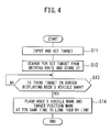
- a target is inputted and set (step S11), and then, the set target is searched for from the driving route to be stored (step S12).
- the position judgment part 10 checks, for example, every five minutes whether there is a restaurant offering Chinese noodles as a target within the same screen as that displaying the user's vehicle position, that is, the user's vehicle mark (step S13).
- the user' s vehicle mark display control part 13 displays the icon 23 of the Chinese noodles restaurant 22 as shown in FIG.
- step S14 links the icon 23 to the restaurant by a connecting line 25, and displays the icon 23 and the Chinese noodles restaurant 22 in the same noticeable color to flash them at the same time (step S14). Any one of linking the icon 23 with the Chinese noodles restaurant 22 by the connecting line 25, displaying the icon 23 and the Chinese noodles restaurant 22 in the same color, and flashing the icon 23 and the Chinese noodles restaurant 22 at the same time may be performed.
- the connecting line 25 may be a line along a road.
- the user's vehicle mark 21 remains the same without being changed to the icon 23.
- the user' s vehicle mark 21 and the Chinese noodles restaurant 22 are clearly associated with each other by the connecting line 25, the same color, and flashing at the same time.
- the Chinese noodles restaurant 22 can be easily grasped.
- the user's vehicle position detection means such as the direction sensor 1 detecting the current position of a user's vehicle, the vehicle speed sensor 2, and the GPS receiver 4, the information data obtaining part 8 obtaining information data including an icon associated with a target, the map data obtaining part 7 obtaining map data, the display part 6 displaying a map corresponding to the user's vehicle position detected by the user's vehicle position detection means with a user' s vehicle mark, and the user' s vehicle mark display control part 13 reading an icon and a description associated with the target from the information data obtaining part 8 to display it in place of the user's vehicle mark when a user's vehicle position has made an approach to within a predetermined distance range from a predetermined target or has entered the same screen.
- the information data obtaining part 8 obtaining information data including an icon associated with a target
- the map data obtaining part 7 obtaining map data
- the display part 6 displaying a map corresponding to the user's vehicle position detected by the user's vehicle position detection means with a user' s
- the target need not be searched for from the map display screen. Having made an approach to the target and its position and description can be easily recognized.
- the user's vehicle position has made an approach to the target, the user's vehicle mark is changed. Having made an approach to the target can be easily noticed.
- the Chinese noodles restaurant is set as the target.
- an icon of a dog or cat can be displayed in place of the user' s vehicle mark.
- the number of items and the contents of an information database may be fulfilled so as to select an icon of a dog or cat of the user's favorite type.
- the user's vehicle drives on the route set by the route search means 11.
- the user's vehicle is stopped once to perform peripheral facility search by narrowing down to a predetermined distance from a user's vehicle position, e.g., within the range of 5 or 10 kilometers.
- a predetermined distance e.g., within the range of 5 or 10 kilometers.
- the "user's vehicle position display marking information" is inputted and set because a target is different for each drive. In driving on the same route like a regularly running truck, the same target is often selected. In such a case, the inputted and set "user's vehicle position display marking information" is stored. Without inputting and setting it next time, when the user's vehicle position has made an approach to a target of the same type, an icon can be automatically displayed. In this case, the "user's vehicle position display marking information" can be stored for each inputted and set type and can be erased as necessary.
- an icon about a product, a sightseeing spot, and an event representing the area may be displayed in place of the user's vehicle mark.
- an icon of Mt. Yatsugatake as a sightseeing spot representing Yamanashi Prefecture is displayed.
- an icon of a pear, grapes, or a peach as a product representing Yamanashi Prefecture is sequentially displayed. The user can recognize that the user's vehicle position has entered Yamanashi Prefecture.
- Information data including marking information obtained by the information data obtaining part 8 is updated to a new version to use the latest information.
- the user's vehicle position display device and method according to the present invention can enhance the viewability of necessary information simply by seeing the user's vehicle mark.
- the user's vehicle position display device and method according to the present invention are useful for a route guiding device or a navigation device which detects the current position of a user's vehicle to read road map data corresponding to the user's vehicle position and displays the user's vehicle mark on the road map displayed on the display to guide a route.
- the user's vehicle position display device and method according to the present invention can be applied to a portable route guiding device.
Abstract

Description
- The present invention relates to a moving object position display device and method which detect the current position of a moving object to read road map data corresponding to the moving object position and display a moving object mark on the road map displayed on the display to guide a route.
- A vehicle navigation device is given as an example of a moving object position display device. The related art navigation device detects the current position of a user's vehicle as a moving object by current position detection means such as a GPS (Global Positioning System) receiver. The navigation device reads road map data corresponding to the current position from a storage medium such as a DVD (Digital Versatile Disc)-ROM to display the map on the display. The navigation device searches for a recommended route to a destination set by the user using route search means. The navigation device displays the recommended route overlapped with the map on the display with a user' s vehicle mark, thereby guiding the user to the destination. When the user's vehicle position makes an approach to a junction such as an intersection and an interchange, its enlarged view and three-dimensional view are displayed to guide a driving direction and a distance to a reaching point by voice. Road traffic information such as traffic jam information on a route is obtained from a road beacon or FM multiplex broadcasting in VICS (Vehicle Information and Communication Systems) to be displayed on the display.
- A user's vehicle mark displayed on the map on the display is very important for indicating the current position of a user' s vehicle. The displayed position of the user's vehicle mark is determined by map matching of the detected result of the current position detection means with the road map data. When there is a problem in the detection accuracy of the current position detection means, the user's vehicle mark will be displayed to be off the road or displayed on a different road. There has been proposed a navigation device which judges the position state of a user's vehicle mark and changes the display form of a display object (such as a facility, river, and one-way road) in which the user' s vehicle mark on a map display screen is positioned so that the user can easily recognize the current state (see Japanese Patent Application Publication No. 2002-340590). An attempt to provide additional information to a user' s vehicle mark itself has been made. There has been known a driving guiding device which changes the color of a user's vehicle mark in the case of detecting a user's vehicle position by radio navigation using a GPS receiver and of detecting a user's vehicle position by autonomous navigation using a direction sensor and a speed sensor (see Japanese Patent Application Publication No. Hei 03-131714).
- The related art navigation device cannot be sufficient although an attempt to provide additional information to a user's vehicle mark itself has been made. In driving using the navigation device, a driving route from the current position to a destination is displayed. When searching for a facility such as a restaurant during driving, the user needs to stop the vehicle once to check it. A lot of location information or landmark information on the facility is displayed on the map screen displayed on the display. It is not preferable to search for it while driving.
- The present invention has been made in view of such related art problems and an object of the present invention is to provide a moving object position display device and method which enhance viewability of necessary information and improve convenience.
- To address the above problems, a moving object position display device according to the present invention has moving object position detection means for detecting a moving object position; moving object position judgment means for judging whether or not the moving object position has made an approach to within a predetermined distance range from a predetermined target; and display control means for, when the moving object position has made an approach to within the predetermined distance range from the predetermined target, displaying a moving object mark indicating the moving obj ect position by marking information associated with the target.
- According to this configuration, when the user's vehicle position has made an approach to a target which the user is going to or a target the user is searching for, in place of the related art moving object mark or with the related art moving object mark, marking information associated with the target is displayed. The user can easily recognize that the user's vehicle position has made an approach to the target without searching for the target from the map display screen. The moving object position display device according to the present invention can contribute to safer driving and moving. The marking information associated with a target is icon information simply displaying the target or control information for flashing a moving object mark and the target at the same time, displaying them in the same color, linking them by a straight line, or linking them by a route.
- A moving object position display device according to the present invention has moving object position detection means for detecting a moving object position; moving obj ect position judgment means for judging whether or not the moving object position has entered the same screen as that of a predetermined target; and display control means for, when the moving object position has entered the same screen as that of the predetermined target, displaying a moving object mark indicating the moving object position by marking position associated with the target.
- According to this configuration, when a moving object position enters the same screen as that of a target which the user is going to or a target the user is searching for, in place of the related art moving object mark or with the related art moving object mark, marking information associated with the target is displayed. The user can easily recognize that the user's vehicle position has made an approach to the target without searching for the target from the map display screen. The moving object position display device according to the present invention can contribute to safer driving and moving.
- The moving object position display device according to the present invention has input means for setting the predetermined target and setting an icon as the displayed marking information. According to this configuration, a target which the user is going to or a target the user is searching for can be previously set and a favorite icon can be selected from plural icons associated with the target to be displayed.
- In the moving object position display device according to the present invention, the display control means stores the type of the set target, and when the moving object position has made an approach to a target of the same type, displays an icon associated with the target. According to this configuration, an icon associated with a target of the same type can be automatically displayed without inputting and setting the target when the moving object position has made an approach to the target of the type.
- In the moving object position display device according to the present invention, when the moving object position has entered a predetermined area, the display control means displays an icon about a product, a sightseeing spot, or an event representing the area in place of the moving object mark. According to this configuration, when the moving object position display device recognizes that the moving object position has entered a predetermined area based on prefectural boundary information in road map data, for example, when the moving object position has entered Akita Prefecture, it can display an icon of an Akita dog as a product of Akita Prefecture, an icon of a butterbur as a prefectural flower of Akita Prefecture, or an icon of Kanto (a tall bamboo pole that has lanterns attached to it) used for a summer festival of Akita Prefecture.
- In the moving object position display device according to the present invention, the display control means displays information on the target or area with the icon. According to this configuration, more specific information on the target or area can be obtained.
- In the moving object position display device according to the present invention, information data including the marking information can be updated by a storage medium or communication means. According to this configuration, the latest information data can be obtained and a user's favorite icon can be selected.
- In a moving object position display method according to the present invention, in the moving object position display device which displays a detected moving object position on a map displayed on a screen to guide a route, when the moving object position has made an approach to within a predetermined distance range from a predetermined target, a moving object mark indicating the moving object position is displayed by marking information associated with the target.
- According to this configuration, when the moving object position has made an approach to a target which the user is going to or a target the user is searching for, in place of the related art moving object mark or with the related art moving object mark, marking information associated with the target is displayed. The user can easily recognize that the moving object position has made an approach to the target without searching for the target from the map display screen. The moving object position display method according to the present invention can contribute to safer driving and moving.
- In a moving object position display method according to the present invention, in the moving object position display device which displays a detected moving object position on a map displayed on a screen to guide a route, when the moving object position has entered the same screen as that of a predetermined target, a moving object mark indicating the moving object position is displayed by marking information associated with the target.
- According to this configuration, when the moving object position has entered the same screen as that of a target which the user is going to or a target the user is searching for, in place of the related art moving object mark or with the related art moving object mark, marking information associated with the target is displayed. The user can easily recognize that the moving object position has made an approach to the target without searching for the target from the map display screen. The moving object position display method according to the present invention can contribute to safer driving and moving.
- According to the present invention, when the moving object position has made an approach to within a predetermined distance range from a predetermined target or has entered the same screen, the moving object mark indicating the moving object position is changed to the marking information associated with the target to be displayed. When the moving object position has made an approach to a target which the user is going to or a target the user is searching for, in place of the related art moving object mark or with the related art moving object mark, the marking information associated with the target is displayed. The user can easily recognize that the moving obj ect position has made an approach to the target without searching for the target from the map display screen. Viewability of necessary information can be enhanced and convenience can be improved. The moving object position display method according to the present invention can contribute to safer driving and moving. Additional information is provided to the moving object mark which is seen on the display screen most often. Necessary information can be obtained to some extent simply by seeing the moving object mark. The utility value of the navigation device can be enhanced.
- The above object and advantages of the present invention will be further apparent by the following embodiments described with reference to the drawings.
-
- FIG. 1 is a block diagram showing the schematic configuration of a navigation device according to an embodiment of the present invention;
- FIG. 2 is a flowchart showing a user's vehicle mark display control operation according to an embodiment of the present invention;
- FIG. 3 is a schematic diagram illustrating a user's vehicle mark display control operation according to an embodiment of the present invention;
- FIG. 4 is a flowchart showing another user's vehicle mark display control operation according to an embodiment of the present invention; and
- FIG. 5 is a schematic diagram illustrating another user's vehicle mark display control operation according to an embodiment of the present invention.
- Embodiments of the present invention will be described below using the drawings. FIG. 1 shows the schematic configuration of a vehicle navigation device as a moving object position display device according to an embodiment of the present invention. According to this embodiment, the vehicle navigation device will be described as an example of a moving object position display device and can be applied to a position display device of a general moving object (e.g., a cellular phone or a portable terminal) as well as of a vehicle.
- The navigation device has a
direction sensor 1 detecting the moving direction of a moving object such as a vehicle, avehicle speed sensor 2 detecting the speed of a vehicle and generating a pulse according to the number of revolutions of wheels to detect a vehicle speed, a sensorsignal processing part 3 computation-processing a signal from thedirection sensor 1 and thevehicle speed sensor 2, aGPS receiver 4 receiving a radio wave transmitted from a GPS (Global Positioning System) satellite, and aninput part 5 performing various input settings. The navigation device according to this embodiment also has adisplay part 6 displaying a map and a user's vehicle mark, a mapdata obtaining part 7 obtaining road map data from an external device and a storage medium, an informationdata obtaining part 8 obtaining various pieces of information associated with map data from an external device and a storage medium, and acontrol part 9 controlling the operation of the navigation device. - In FIG. 1, the
direction sensor 1 detects the relative driving direction of an automobile and a vibration gyro is used therefor. Thevehicle speed sensor 2 generates a pulse according to the number of revolutions of wheels to detect a vehicle speed. The sensorsignal processing part 3 processes a sensor signal from thedirection sensor 1 and thevehicle speed sensor 2 to compute the moving direction and mileage of a vehicle. TheGPS receiver 4 receives a radio wave transmitted from plural GPS satellites for computation processing and determines the position (latitude and longitude) of a receiving point. Theinput part 5 is a touch panel and a remote control performing input setting of a destination and marking information and other input settings. Thedisplay part 6 is a liquid crystal display displaying information necessary for driving such as a map, a user's vehicle mark, and a driving route. The mapdata obtaining part 7 is a drive, an interface, or communication means obtaining road map data from a storage medium such as a DVD and a memory card or from an external device via a network. The informationdata obtaining part 8 is a drive, interface, or communication means obtaining position information and guide information on a target such as a facility and a sightseeing spot and an area such as a prefecture, city, town, and village and marking information such as an icon associated with a target or an area from a storage medium such as a DVD and a memory card or from an external device via a network. Thecontrol part 9 is a microprocessor controlling the entire navigation device and, in order to control the operation of the navigation device, has aposition judgment part 10 judging in what position on a display screen a detected current position is located and the length of a distance between an inputted and set target and the current position, aroute search part 11 searching for a route to an inputted and set destination, a mapdisplay control part 12 reading map data corresponding to the detected current position or required map data from the mapdata obtaining part 7 to display it on thedisplay part 6, and a user's vehicle markdisplay control part 13 reading marking information corresponding to a target set by the user from theinput part 5 from the informationdata obtaining part 8 to display it in place of or with a user's vehicle mark. - The operation of the thus-configured navigation device will be described. The outline of the navigation operation will be described. In FIG. 1, outputs of the
direction sensor 1 and thevehicle speed sensor 2 are sent via thesensor processing part 3 to thecontrol part 9. Data from the GPS satellite received by theGPS receiver 4 is sent to thecontrol part 9. Thecontrol part 9 computes the latitude and longitude of the current position of a user's vehicle from the data. Map data corresponding to the computed current position is read from the mapdata obtaining part 7. The read map data is converted to image data to be sent to thedisplay part 6. The map within a predetermined range is displayed with the user's vehicle mark. The route to a destination searched for by theroute search part 11 is displayed to be overlapped with the map. The user's vehicle position is changed according to the driving of the vehicle. The corresponding map data is sequentially read to update the map screen. - The user's vehicle mark display control operation of the
control part 9 according to this embodiment will be described using FIG. 2. A user's vehicle drives on a route searched for by theroute search part 11. A target is inputted and set (step S1) . For example, when the user thinks that he/she is going to eat Chinese noodles (Chinese soba) for today's lunch, the user stops the vehicle before starting or while driving to call the menu screen from theinput part 5 and then selects the "User's vehicle position marking information" from the "Search" screen so that the facility types are displayed. The user selects "Eating" and then "Restaurant (Chinese food)". The corresponding plural targets on the driving route are searched for from the informationdata obtaining part 8. Restaurant information such as a charge is stored in a memory in thecontrol part 9 with its position information (step S2). When driving is started in this state, theposition judgment part 10 checks, for example, every five minutes whether there is a restaurant offering Chinese noodles as a target, e.g. , within 500 meters, from the user's vehicle position, that is, the position in which the user's vehicle mark is displayed (step 3). When there is one, in place of a user'svehicle mark 21 currently displayed as shown in FIG. 3A, the user's vehicle markdisplay control part 13 displays anicon 23 of aChinese noodles restaurant 22 as shown in FIG. 3B, and then, restaurant information 24 (step S4) . That the user'svehicle mark 21 has been changed to theicon 23 may be noticed to the user by sound. - Alternatively, as described above, as shown in FIG. 4, a target is inputted and set (step S11), and then, the set target is searched for from the driving route to be stored (step S12). The
position judgment part 10 checks, for example, every five minutes whether there is a restaurant offering Chinese noodles as a target within the same screen as that displaying the user's vehicle position, that is, the user's vehicle mark (step S13). When there is one, in place of the user's vehicle mark 21 currently displayed as shown in FIG. 5A, the user' s vehicle markdisplay control part 13 displays theicon 23 of theChinese noodles restaurant 22 as shown in FIG. 5B, links theicon 23 to the restaurant by a connectingline 25, and displays theicon 23 and theChinese noodles restaurant 22 in the same noticeable color to flash them at the same time (step S14). Any one of linking theicon 23 with theChinese noodles restaurant 22 by the connectingline 25, displaying theicon 23 and theChinese noodles restaurant 22 in the same color, and flashing theicon 23 and theChinese noodles restaurant 22 at the same time may be performed. The connectingline 25 may be a line along a road. In this example, the user'svehicle mark 21 remains the same without being changed to theicon 23. The user's vehicle mark 21 and theChinese noodles restaurant 22 are clearly associated with each other by the connectingline 25, the same color, and flashing at the same time. TheChinese noodles restaurant 22 can be easily grasped. - According to this embodiment, it has the user's vehicle position detection means such as the
direction sensor 1 detecting the current position of a user's vehicle, thevehicle speed sensor 2, and theGPS receiver 4, the informationdata obtaining part 8 obtaining information data including an icon associated with a target, the mapdata obtaining part 7 obtaining map data, thedisplay part 6 displaying a map corresponding to the user's vehicle position detected by the user's vehicle position detection means with a user' s vehicle mark, and the user' s vehicle markdisplay control part 13 reading an icon and a description associated with the target from the informationdata obtaining part 8 to display it in place of the user's vehicle mark when a user's vehicle position has made an approach to within a predetermined distance range from a predetermined target or has entered the same screen. The target need not be searched for from the map display screen. Having made an approach to the target and its position and description can be easily recognized. When the user's vehicle position has made an approach to the target, the user's vehicle mark is changed. Having made an approach to the target can be easily noticed. - According to the above embodiment, the Chinese noodles restaurant is set as the target. When searching for a pet shop in the same manner, an icon of a dog or cat can be displayed in place of the user' s vehicle mark. In this case, the number of items and the contents of an information database may be fulfilled so as to select an icon of a dog or cat of the user's favorite type.
- According to the above embodiment, the user's vehicle drives on the route set by the route search means 11. When the user's vehicle does not drive on the set route or drives without setting any route, the user's vehicle is stopped once to perform peripheral facility search by narrowing down to a predetermined distance from a user's vehicle position, e.g., within the range of 5 or 10 kilometers. After the position information obtained by this search is stored, as in the above embodiment, when the user's vehicle has entered within the range of 500 meters from the target or in the same screen, the user's vehicle mark can be changed.
- According to this embodiment, before starting driving or while driving, the "user's vehicle position display marking information" is inputted and set because a target is different for each drive. In driving on the same route like a regularly running truck, the same target is often selected. In such a case, the inputted and set "user's vehicle position display marking information" is stored. Without inputting and setting it next time, when the user's vehicle position has made an approach to a target of the same type, an icon can be automatically displayed. In this case, the "user's vehicle position display marking information" can be stored for each inputted and set type and can be erased as necessary.
- According to this embodiment, when prefectural boundary information on a prefecture, a city, a town, and a village included in the road map data and is obtained, an icon about a product, a sightseeing spot, and an event representing the area may be displayed in place of the user's vehicle mark. When the user's vehicle position enters Yamanashi Prefecture, an icon of Mt. Yatsugatake as a sightseeing spot representing Yamanashi Prefecture is displayed. Then, an icon of a pear, grapes, or a peach as a product representing Yamanashi Prefecture is sequentially displayed. The user can recognize that the user's vehicle position has entered Yamanashi Prefecture.
- Information data including marking information obtained by the information
data obtaining part 8 is updated to a new version to use the latest information. - As is apparent from the above description, the user's vehicle position display device and method according to the present invention can enhance the viewability of necessary information simply by seeing the user's vehicle mark. The user's vehicle position display device and method according to the present invention are useful for a route guiding device or a navigation device which detects the current position of a user's vehicle to read road map data corresponding to the user's vehicle position and displays the user's vehicle mark on the road map displayed on the display to guide a route. The user's vehicle position display device and method according to the present invention can be applied to a portable route guiding device.
- The present invention is described above based on the preferred embodiments shown in the drawings. It is apparent that those skilled in the art can easily make various changes and modifications without departing from the idea of the present invention. The present invention includes such modification examples.
Claims (14)
- A moving object position display device comprising: moving object position judgment means for judging whether or not a moving object position has made an approach to within a predetermined distance range from a predetermined target; and display control means for, when said moving object position has made an approach to within the predetermined distance range from the predetermined target, displaying a moving object mark indicating said moving object position by marking information associated with said target.
- A moving object position display device comprising: moving object position judgment means for judging whether or not a moving object position has entered the same screen as that of a predetermined target ; and display control means for, when said moving object position has entered the same screen as that of the predetermined target, displaying a moving object mark indicating the moving object position by marking information associated with said target.
- The moving object position display device according to claim 1, further comprising input means for setting said predetermined target and setting an icon as said displayed marking information.
- The moving object position display device according to claim 2, further comprising input means for setting said predetermined target and setting an icon as said displayed marking information.
- The moving object position display device according to claim 3, wherein said display control means stores the type of said set target, and when a user's vehicle position has made an approach to a target of the same type, displays an icon associated with said target.
- The moving object position display device according to claim 4, wherein said display control means stores the type of said set target, and when a user's vehicle position has made an approach to a target of the same type, displays an icon associated with said target.
- The moving object position display device according to claim 1, wherein said display control means, when a user's vehicle position has entered a predetermined area, displays an icon about a product, a sightseeing spot, and an event representing the area in place of a moving object mark.
- The moving object position display device according to claim 2, wherein said display control means, when a user's vehicle position has entered a predetermined area, displays an icon about a product, a sightseeing spot, and an event representing the area in place of a moving object mark.
- The moving object position display device according to claim 7, wherein said display control means displays information on said target or area with said icon.
- The moving object position display device according to claim 8, wherein said display control means displays information on said target or area with said icon.
- The moving object position display device according to claim 1, wherein information data including said marking information can be updated by a storage medium or communication means.
- The moving object position display device according to claim 2, wherein information data including said marking information can be updated by a storage medium or communication means.
- A moving object position display method comprising the steps of:displaying a map on a screen;detecting a moving object position;displaying a moving object mark indicating the detected moving object position on the map displayed on said screen to guide a route;searching for a predetermined target based on a driving route;detecting whether or not said moving object position has made an approach to within a predetermined distance range from said target; andwhen detecting that said moving obj ect position has made an approach to within the predetermined distance range from the predetermined target, displaying a moving object mark indicating the moving object position by marking information associated with said target.
- A moving object position display method comprising the steps of:displaying a map on a screen;detecting a moving object position;displaying a moving object mark indicating the detected moving object position on the map displayed on said screen to guide a route;searching for a predetermined target based on a driving route;detecting whether or not said moving object position has entered the same screen as that of said target; andwhen detecting that said moving object position has entered the same screen as that of the predetermined target, displaying a moving object mark indicating the moving object position by marking information associated with said target.
Applications Claiming Priority (2)
| Application Number | Priority Date | Filing Date | Title |
|---|---|---|---|
| JP2003309065 | 2003-09-01 | ||
| PCT/JP2004/012760 WO2005022086A1 (en) | 2003-09-01 | 2004-08-27 | Moving object position display device and method |
Publications (3)
| Publication Number | Publication Date |
|---|---|
| EP1666843A1 true EP1666843A1 (en) | 2006-06-07 |
| EP1666843A4 EP1666843A4 (en) | 2009-06-17 |
| EP1666843B1 EP1666843B1 (en) | 2010-11-03 |
Family
ID=34269542
Family Applications (1)
| Application Number | Title | Priority Date | Filing Date |
|---|---|---|---|
| EP04772709A Active EP1666843B1 (en) | 2003-09-01 | 2004-08-27 | Moving object position display device and method |
Country Status (6)
| Country | Link |
|---|---|
| US (1) | US7471215B2 (en) |
| EP (1) | EP1666843B1 (en) |
| JP (1) | JP4402047B2 (en) |
| CN (1) | CN1846115B (en) |
| DE (1) | DE602004029908D1 (en) |
| WO (1) | WO2005022086A1 (en) |
Cited By (1)
| Publication number | Priority date | Publication date | Assignee | Title |
|---|---|---|---|---|
| US10575135B2 (en) | 2016-05-24 | 2020-02-25 | Kyocera Corporation | Portable electronic device, method of controlling portable electronic device, and non-transitory computer-readable medium |
Families Citing this family (14)
| Publication number | Priority date | Publication date | Assignee | Title |
|---|---|---|---|---|
| US8285481B2 (en) * | 2006-08-10 | 2012-10-09 | Alpine Electronics, Inc. | Method and apparatus for associating brand icon with POI location for navigation system |
| JP5055006B2 (en) * | 2007-04-13 | 2012-10-24 | クラリオン株式会社 | In-vehicle map display device |
| WO2009014081A1 (en) * | 2007-07-23 | 2009-01-29 | Clarion Co., Ltd. | Navigation device |
| CN101413802B (en) * | 2007-10-19 | 2011-11-23 | 神达电脑股份有限公司 | Navigation system and structure for providing terminal user content |
| TWI402481B (en) * | 2009-10-16 | 2013-07-21 | Mitac Int Corp | Method for displaying activity information on a navigation device and related navigation device |
| JP5435046B2 (en) * | 2012-01-19 | 2014-03-05 | 横河電機株式会社 | Device information display apparatus and method |
| CN104134398B (en) * | 2013-05-03 | 2017-08-25 | 腾讯科技(深圳)有限公司 | A kind of method and device for showing map details information |
| DE112014003177T5 (en) * | 2013-07-08 | 2016-03-31 | Honda Motor Co., Ltd. | Object detection device |
| US9582886B2 (en) | 2013-07-08 | 2017-02-28 | Honda Motor Co., Ltd. | Object recognition device |
| KR102156021B1 (en) * | 2014-03-31 | 2020-09-16 | 현대엠엔소프트 주식회사 | Navigation route guidance system using avatars |
| JP6661883B2 (en) * | 2015-02-09 | 2020-03-11 | 株式会社デンソー | Vehicle display control device and vehicle display control method |
| CN105320749A (en) * | 2015-09-29 | 2016-02-10 | 小米科技有限责任公司 | Travel route generation method and apparatus |
| JP6833758B2 (en) * | 2018-04-26 | 2021-02-24 | 京セラ株式会社 | Portable electronic devices, portable electronic device control methods and portable electronic device control programs |
| CN111750892A (en) * | 2019-03-26 | 2020-10-09 | 阿里巴巴集团控股有限公司 | Electronic map display method and device, medium and terminal |
Citations (2)
| Publication number | Priority date | Publication date | Assignee | Title |
|---|---|---|---|---|
| EP0762362A2 (en) * | 1995-09-08 | 1997-03-12 | Aisin Aw Co., Ltd. | Navigation system for vehicles |
| US6321160B1 (en) * | 1999-03-31 | 2001-11-20 | Matsushita Electric Industrial Co., Ltd. | Navigation apparatus |
Family Cites Families (7)
| Publication number | Priority date | Publication date | Assignee | Title |
|---|---|---|---|---|
| JP2885849B2 (en) | 1989-10-17 | 1999-04-26 | マツダ株式会社 | Vehicle guidance system |
| US6388688B1 (en) * | 1999-04-06 | 2002-05-14 | Vergics Corporation | Graph-based visual navigation through spatial environments |
| KR100727903B1 (en) * | 2000-05-26 | 2007-06-14 | 삼성전자주식회사 | Apparatus for processing adjacent position information system and method thereof |
| JP2002257556A (en) * | 2001-02-27 | 2002-09-11 | Fujitsu Ten Ltd | Navigation system |
| JP4169491B2 (en) | 2001-05-11 | 2008-10-22 | 三菱電機株式会社 | Mobile navigation device |
| US6909968B2 (en) * | 2002-11-30 | 2005-06-21 | Alpine Electronics, Inc. | Arrival detection method for navigation system |
| US6968973B2 (en) * | 2003-05-31 | 2005-11-29 | Microsoft Corporation | System and process for viewing and navigating through an interactive video tour |
-
2004
- 2004-08-27 EP EP04772709A patent/EP1666843B1/en active Active
- 2004-08-27 WO PCT/JP2004/012760 patent/WO2005022086A1/en active Application Filing
- 2004-08-27 JP JP2005513540A patent/JP4402047B2/en not_active Expired - Fee Related
- 2004-08-27 CN CN2004800251095A patent/CN1846115B/en active Active
- 2004-08-27 DE DE602004029908T patent/DE602004029908D1/en active Active
- 2004-08-27 US US10/570,106 patent/US7471215B2/en active Active
Patent Citations (2)
| Publication number | Priority date | Publication date | Assignee | Title |
|---|---|---|---|---|
| EP0762362A2 (en) * | 1995-09-08 | 1997-03-12 | Aisin Aw Co., Ltd. | Navigation system for vehicles |
| US6321160B1 (en) * | 1999-03-31 | 2001-11-20 | Matsushita Electric Industrial Co., Ltd. | Navigation apparatus |
Non-Patent Citations (1)
| Title |
|---|
| See also references of WO2005022086A1 * |
Cited By (1)
| Publication number | Priority date | Publication date | Assignee | Title |
|---|---|---|---|---|
| US10575135B2 (en) | 2016-05-24 | 2020-02-25 | Kyocera Corporation | Portable electronic device, method of controlling portable electronic device, and non-transitory computer-readable medium |
Also Published As
| Publication number | Publication date |
|---|---|
| JP4402047B2 (en) | 2010-01-20 |
| CN1846115B (en) | 2011-12-14 |
| JPWO2005022086A1 (en) | 2006-10-26 |
| EP1666843B1 (en) | 2010-11-03 |
| US7471215B2 (en) | 2008-12-30 |
| EP1666843A4 (en) | 2009-06-17 |
| DE602004029908D1 (en) | 2010-12-16 |
| WO2005022086A1 (en) | 2005-03-10 |
| US20070109148A1 (en) | 2007-05-17 |
| CN1846115A (en) | 2006-10-11 |
Similar Documents
| Publication | Publication Date | Title |
|---|---|---|
| US9052212B2 (en) | Dynamic destination map display for navigation system | |
| US6574552B2 (en) | Navigation system and computer-readable information recorded medium in which navigation control program is recorded | |
| US6732049B2 (en) | Vehicle navigation system and method | |
| EP1666843B1 (en) | Moving object position display device and method | |
| US7813874B2 (en) | On-vehicle navigation system, route guide method, and computer-readable recording medium | |
| EP0833291A1 (en) | Vehicle navigation apparatus and storage medium | |
| JP2003247837A (en) | On-vehicle navigation system | |
| US20040002303A1 (en) | Data terminal device | |
| US7054744B2 (en) | Route provision apparatus, route provision method, navigation system, and computer program for route provision apparatus or navigation system | |
| JP2002342330A (en) | Navigation system | |
| JP2005326265A (en) | Display method for updated information of navigation system and running road | |
| JP2008122340A (en) | Navigation system | |
| JP2007256020A (en) | Navigation device, navigation method, and navigation program | |
| JP2005233972A (en) | Navigation device | |
| JPH07301543A (en) | Navigation device | |
| JP2004177199A (en) | Car navigation apparatus, car navigation method, program, and recording medium | |
| JP2003021527A (en) | Navigation device, display method and program | |
| JP2003207352A (en) | Navigation system and route search method | |
| KR100981179B1 (en) | Apparatus and method for providing point of interest based on time | |
| JP3879861B2 (en) | Navigation device and navigation method | |
| JP2005227293A (en) | Navigation system and method | |
| KR101089341B1 (en) | Car Navigation System and Method for Navigation Service of that | |
| KR20100137270A (en) | Method and apparatus for searching menu in a navigation device | |
| JPH11248469A (en) | Navigation device | |
| JP2013137247A (en) | Navigation device |
Legal Events
| Date | Code | Title | Description |
|---|---|---|---|
| PUAI | Public reference made under article 153(3) epc to a published international application that has entered the european phase |
Free format text: ORIGINAL CODE: 0009012 |
|
| 17P | Request for examination filed |
Effective date: 20060301 |
|
| AK | Designated contracting states |
Kind code of ref document: A1 Designated state(s): DE FR GB |
|
| DAX | Request for extension of the european patent (deleted) | ||
| RBV | Designated contracting states (corrected) |
Designated state(s): DE FR GB |
|
| RAP1 | Party data changed (applicant data changed or rights of an application transferred) |
Owner name: PANASONIC CORPORATION |
|
| A4 | Supplementary search report drawn up and despatched |
Effective date: 20090514 |
|
| RIC1 | Information provided on ipc code assigned before grant |
Ipc: G08G 1/0969 20060101ALI20050317BHEP Ipc: G01C 21/36 20060101AFI20090508BHEP |
|
| 17Q | First examination report despatched |
Effective date: 20091012 |
|
| GRAP | Despatch of communication of intention to grant a patent |
Free format text: ORIGINAL CODE: EPIDOSNIGR1 |
|
| GRAS | Grant fee paid |
Free format text: ORIGINAL CODE: EPIDOSNIGR3 |
|
| GRAA | (expected) grant |
Free format text: ORIGINAL CODE: 0009210 |
|
| AK | Designated contracting states |
Kind code of ref document: B1 Designated state(s): DE FR GB |
|
| REG | Reference to a national code |
Ref country code: GB Ref legal event code: FG4D |
|
| REF | Corresponds to: |
Ref document number: 602004029908 Country of ref document: DE Date of ref document: 20101216 Kind code of ref document: P |
|
| PLBE | No opposition filed within time limit |
Free format text: ORIGINAL CODE: 0009261 |
|
| STAA | Information on the status of an ep patent application or granted ep patent |
Free format text: STATUS: NO OPPOSITION FILED WITHIN TIME LIMIT |
|
| 26N | No opposition filed |
Effective date: 20110804 |
|
| REG | Reference to a national code |
Ref country code: DE Ref legal event code: R097 Ref document number: 602004029908 Country of ref document: DE Effective date: 20110804 |
|
| REG | Reference to a national code |
Ref country code: FR Ref legal event code: PLFP Year of fee payment: 13 |
|
| REG | Reference to a national code |
Ref country code: FR Ref legal event code: PLFP Year of fee payment: 14 |
|
| REG | Reference to a national code |
Ref country code: FR Ref legal event code: PLFP Year of fee payment: 15 |
|
| REG | Reference to a national code |
Ref country code: DE Ref legal event code: R084 Ref document number: 602004029908 Country of ref document: DE |
|
| PGFP | Annual fee paid to national office [announced via postgrant information from national office to epo] |
Ref country code: FR Payment date: 20221027 Year of fee payment: 20 |
|
| PGFP | Annual fee paid to national office [announced via postgrant information from national office to epo] |
Ref country code: GB Payment date: 20230706 Year of fee payment: 20 |
|
| PGFP | Annual fee paid to national office [announced via postgrant information from national office to epo] |
Ref country code: DE Payment date: 20221029 Year of fee payment: 20 |
|
| REG | Reference to a national code |
Ref country code: DE Ref legal event code: R081 Ref document number: 602004029908 Country of ref document: DE Owner name: PANASONIC AUTOMOTIVE SYSTEMS CO., LTD., YOKOHA, JP Free format text: FORMER OWNER: PANASONIC CORPORATION, KADOMA-SHI, OSAKA, JP |