EP1666784A1 - Fluid conduit wall inhibiting heat transfer and method for making - Google Patents
Fluid conduit wall inhibiting heat transfer and method for making Download PDFInfo
- Publication number
- EP1666784A1 EP1666784A1 EP04257586A EP04257586A EP1666784A1 EP 1666784 A1 EP1666784 A1 EP 1666784A1 EP 04257586 A EP04257586 A EP 04257586A EP 04257586 A EP04257586 A EP 04257586A EP 1666784 A1 EP1666784 A1 EP 1666784A1
- Authority
- EP
- European Patent Office
- Prior art keywords
- conduit
- wall
- coating
- fluid
- radially
- Prior art date
- Legal status (The legal status is an assumption and is not a legal conclusion. Google has not performed a legal analysis and makes no representation as to the accuracy of the status listed.)
- Granted
Links
- 239000012530 fluid Substances 0.000 title claims abstract description 79
- 238000000034 method Methods 0.000 title claims abstract description 13
- 230000002401 inhibitory effect Effects 0.000 title description 3
- 238000000576 coating method Methods 0.000 claims abstract description 133
- 239000011248 coating agent Substances 0.000 claims abstract description 113
- 238000009834 vaporization Methods 0.000 claims abstract description 6
- 230000008016 vaporization Effects 0.000 claims abstract description 6
- 229910052751 metal Inorganic materials 0.000 claims description 26
- 239000002184 metal Substances 0.000 claims description 26
- 239000002356 single layer Substances 0.000 claims description 17
- 229910052737 gold Inorganic materials 0.000 claims description 9
- 229910052697 platinum Inorganic materials 0.000 claims description 9
- 229910052742 iron Inorganic materials 0.000 claims description 6
- 229910001092 metal group alloy Inorganic materials 0.000 claims description 6
- 229910052759 nickel Inorganic materials 0.000 claims description 6
- 238000000151 deposition Methods 0.000 claims description 5
- 239000007789 gas Substances 0.000 description 10
- 238000009413 insulation Methods 0.000 description 9
- BASFCYQUMIYNBI-UHFFFAOYSA-N platinum Substances [Pt] BASFCYQUMIYNBI-UHFFFAOYSA-N 0.000 description 9
- 125000006850 spacer group Chemical group 0.000 description 9
- 238000011156 evaluation Methods 0.000 description 5
- 239000007788 liquid Substances 0.000 description 5
- 239000002243 precursor Substances 0.000 description 5
- 229910045601 alloy Inorganic materials 0.000 description 4
- 239000000956 alloy Substances 0.000 description 4
- 239000000463 material Substances 0.000 description 4
- 238000004519 manufacturing process Methods 0.000 description 3
- 229910000510 noble metal Inorganic materials 0.000 description 3
- 230000001627 detrimental effect Effects 0.000 description 2
- 238000010438 heat treatment Methods 0.000 description 2
- 238000010301 surface-oxidation reaction Methods 0.000 description 2
- KLFRPGNCEJNEKU-FDGPNNRMSA-L (z)-4-oxopent-2-en-2-olate;platinum(2+) Chemical compound [Pt+2].C\C([O-])=C\C(C)=O.C\C([O-])=C\C(C)=O KLFRPGNCEJNEKU-FDGPNNRMSA-L 0.000 description 1
- 238000010521 absorption reaction Methods 0.000 description 1
- 230000015572 biosynthetic process Effects 0.000 description 1
- 238000005219 brazing Methods 0.000 description 1
- 239000000919 ceramic Substances 0.000 description 1
- 238000005229 chemical vapour deposition Methods 0.000 description 1
- 239000000567 combustion gas Substances 0.000 description 1
- 239000000356 contaminant Substances 0.000 description 1
- 230000000694 effects Effects 0.000 description 1
- 230000002708 enhancing effect Effects 0.000 description 1
- 229910001119 inconels 625 Inorganic materials 0.000 description 1
- 239000011810 insulating material Substances 0.000 description 1
- 238000005304 joining Methods 0.000 description 1
- 239000010410 layer Substances 0.000 description 1
- 150000002736 metal compounds Chemical class 0.000 description 1
- 229910052755 nonmetal Inorganic materials 0.000 description 1
- 230000000149 penetrating effect Effects 0.000 description 1
- MBUJACWWYFPMDK-UHFFFAOYSA-N pentane-2,4-dione;platinum Chemical compound [Pt].CC(=O)CC(C)=O MBUJACWWYFPMDK-UHFFFAOYSA-N 0.000 description 1
- 230000000717 retained effect Effects 0.000 description 1
- 238000007493 shaping process Methods 0.000 description 1
- 239000002904 solvent Substances 0.000 description 1
- 230000003068 static effect Effects 0.000 description 1
- 239000000758 substrate Substances 0.000 description 1
Images
Classifications
-
- F—MECHANICAL ENGINEERING; LIGHTING; HEATING; WEAPONS; BLASTING
- F16—ENGINEERING ELEMENTS AND UNITS; GENERAL MEASURES FOR PRODUCING AND MAINTAINING EFFECTIVE FUNCTIONING OF MACHINES OR INSTALLATIONS; THERMAL INSULATION IN GENERAL
- F16L—PIPES; JOINTS OR FITTINGS FOR PIPES; SUPPORTS FOR PIPES, CABLES OR PROTECTIVE TUBING; MEANS FOR THERMAL INSULATION IN GENERAL
- F16L59/00—Thermal insulation in general
- F16L59/08—Means for preventing radiation, e.g. with metal foil
-
- F—MECHANICAL ENGINEERING; LIGHTING; HEATING; WEAPONS; BLASTING
- F16—ENGINEERING ELEMENTS AND UNITS; GENERAL MEASURES FOR PRODUCING AND MAINTAINING EFFECTIVE FUNCTIONING OF MACHINES OR INSTALLATIONS; THERMAL INSULATION IN GENERAL
- F16L—PIPES; JOINTS OR FITTINGS FOR PIPES; SUPPORTS FOR PIPES, CABLES OR PROTECTIVE TUBING; MEANS FOR THERMAL INSULATION IN GENERAL
- F16L11/00—Hoses, i.e. flexible pipes
- F16L11/20—Double-walled hoses
-
- F—MECHANICAL ENGINEERING; LIGHTING; HEATING; WEAPONS; BLASTING
- F16—ENGINEERING ELEMENTS AND UNITS; GENERAL MEASURES FOR PRODUCING AND MAINTAINING EFFECTIVE FUNCTIONING OF MACHINES OR INSTALLATIONS; THERMAL INSULATION IN GENERAL
- F16L—PIPES; JOINTS OR FITTINGS FOR PIPES; SUPPORTS FOR PIPES, CABLES OR PROTECTIVE TUBING; MEANS FOR THERMAL INSULATION IN GENERAL
- F16L59/00—Thermal insulation in general
- F16L59/06—Arrangements using an air layer or vacuum
- F16L59/07—Arrangements using an air layer or vacuum the air layer being enclosed by one or more layers of insulation
-
- F—MECHANICAL ENGINEERING; LIGHTING; HEATING; WEAPONS; BLASTING
- F16—ENGINEERING ELEMENTS AND UNITS; GENERAL MEASURES FOR PRODUCING AND MAINTAINING EFFECTIVE FUNCTIONING OF MACHINES OR INSTALLATIONS; THERMAL INSULATION IN GENERAL
- F16L—PIPES; JOINTS OR FITTINGS FOR PIPES; SUPPORTS FOR PIPES, CABLES OR PROTECTIVE TUBING; MEANS FOR THERMAL INSULATION IN GENERAL
- F16L9/00—Rigid pipes
- F16L9/18—Double-walled pipes; Multi-channel pipes or pipe assemblies
Definitions
- This invention relates to a conduit for the flow of a fluid and, more particularly, to a conduit including a low emissivity coating disposed to inhibit heat transfer through a wall of the conduit.
- Power generating apparatus for example an aircraft gas turbine engine, as well as various well-known flight vehicles, can be subject during operation to conditions producing undesirable atmospheric icing on components.
- icing can occur at and/or within such areas as an engine inlet or engine nacelle, as well as at various external surfaces of the vehicle.
- various anti-ice systems have been included in such apparatus.
- a heated fluid for example heated air from a turbine engine
- a complex conduit such as relatively long, spaced-apart double wall tubing including bends about other components
- an outer surface of a heated anti-ice conduit potentially can be subject to contact with flammable fluids, one example of which is hydraulic fluid, leaking from another component and having an auto-ignition temperature lower than the temperature of the outer surface of the heated conduit. In that example, should a failure occur in a system adjacent the conduit, flammable fluid contacting an outer surface of an anti-ice conduit at a temperature at or above such auto-ignition temperature can result in a fire within the apparatus.
- Provision of a conduit wall with a coating that is very thin, light weight and effectively can inhibit heat transfer through the conduit wall can increase apparatus operating efficiency.
- a coating that can be provided on the conduit wall prior to assembly in an apparatus can reduce apparatus assembly time and thereby reduce the cost of the apparatus.
- the present invention in one embodiment, provides a fluid conduit enclosing a hollow interior for the flow of fluid therein.
- the fluid conduit comprises a conduit wall of a metal alloy and a single layer metallic coating on a wall outer surface.
- the conduit wall includes a wall inner surface exposed to the fluid and a wall outer surface having a wall emissivity of at least about 0.4 prior to use.
- the single layer metallic coating on the wall outer surface is a low emissivity metallic coating having a coating emissivity of less than 0.2 and a coating thickness at least sufficient to provide the coating emissivity and a thickness of no greater than 5000 angstroms.
- the double wall structure comprises an outer wall having an inner surface and an inner wall having an outer surface.
- the method comprises assembling a pair of coaxial hollow conduit members disposed with a smaller inner member within and spaced-apart from a larger outer member. An inner surface of the wall of the outer member is maintained in a spaced-apart position from an outer surface of the wall of the inner member to define a gap therebetween. Then the low emissivity coating is deposited on the assembled conduit from within the gap concurrently on the inner surface of the outer member wall and the outer surface of the inner member wall.
- the assembled double walled fluid conduit is shaped with bends, prior to depositing the coating, for subsequent assembly about associated apparatus.
- bypass turbofan engines Some current commercial forms of aircraft gas turbine engines sometimes are referred to as bypass turbofan engines or, more simply, fan engines.
- such an engine includes a turbojet as a core of the engine and a duct enclosing a multi-blade fan radially outwardly of and surrounding the core.
- air is directed to flow through the core as well as through the outer duct.
- an engine nacelle Radially outward of the fan is an engine nacelle that can enclose flammable fluid carrying apparatus as well as long, hollow, appropriately shaped metallic anti-ice conduit or tubing.
- such a conduit has been constructed as a shaped, spaced-apart double wall structure with ambient, static air in a gap between inner and outer conduit members.
- spacers maintain the members in the spaced-apart relationship.
- a long conduit is provided in shaped segments that are joined during assembly, typically at cooperating flanges.
- heated air for example from the engine compressor at a temperature in the range of about 800 - 1200° F, flows through the long, complex shaped conduit hollow interior from the engine to selected engine or nacelle surfaces. Heated fluid in the anti-ice conduit heats such surfaces to avoid detrimental ice formation that can occur under certain low temperature operating conditions.
- the walls of the conduit typically are made of a metal having a wall surface emissivity of at least about 0.4 before use and up to about 0.8 or more after operation use as a result of surface oxidation.
- a metal having a wall surface emissivity of at least about 0.4 before use and up to about 0.8 or more after operation use as a result of surface oxidation.
- flammable fluid having a relatively low auto-ignition temperature for example as low as about 450° F, can come in contact with the insulation and ignite at the heated surface of the conduit.
- emissivity is used herein in accordance with accepted, well-known heat transfer theory in which emissivity is the ratio of emission of a surface to emission of a black body.
- a conduit wall outer surface of a low emissivity coating of a selected combination of emissivity and thickness can result, through inhibiting thermal emission from a wall surface, in reduction of the temperature of another surface to below a selected temperature.
- a selected temperature has been the auto-ignition temperature of a flammable fluid potentially contacting such surface, for example at about 700° F for a typical flammable hydraulic fluid.
- the coating has a coating emissivity of less than 0.2, preferably in the range of about 0.05 - 0.1, in combination with a thickness of no greater than 5000 angstroms, preferably in the range of about 1000 - 2000 angstroms.
- a coating emissivity of less than 0.2 can be achieved with a metal coating based on at least one noble metal such as Pt or Au or their combinations with a thickness in the range of about 1000 - 2000 angstroms. Because such coatings are costly, it is desirable to avoid their thickness being greater than is effective for providing the selected coating emissivity. Therefore, in one form according to the present invention, the low emissivity coating thickness is sufficient to provide a selected coating emissivity of less than 0.2, and for practical purposes no greater than 5000 angstroms. For gas turbine engine applications, it is preferred that the coating be stable at a temperature of at least about 800° F. Current, low emissivity coatings capable of meeting such requirements have been reported, for example coatings based on at least one noble metal, typically Pt or Au or their combination.
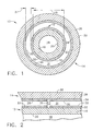
- Conduit 10 comprises a first member shown generally at 12 as a circular cross section tube disposed co-axially, radially within, second member shown generally at 14 as another circular cross section tube.
- First member 12 has an outside diameter 15.
- Such double wall structure provides added insurance for containment of fluid within first member 12 in the event of a rupture of first member 12.
- such structure enables provision, in accordance with the present invention, of the external surface temperature of conduit 10 to be below a selected auto-ignition temperature of a flammable fluid used in apparatus in the vicinity of the conduit.
- First member 12 comprises a metal first conduit wall 16 enclosing a hollow interior 18 for the flow of fluid axially therein.
- First wall 16 includes a first wall inner surface 20 and a first wall outer surface 22.
- Second member 14, disposed co-axially radially spaced-apart about first member 12 includes a metal second wall 26 having a second wall inner surface 28 and a second wall outer surface 30.
- Such disposition of the first and second members defines gap 31 therebetween.
- relatively long co-axial double wall conduit members or segments have been maintained spaced apart one from another by thin, ring-like, pronged spacers, one of which is shown in Figure 2. Such spacers are disposed between the members in gap 31 periodically, axially along the conduit length.
- co-axial members in relatively short conduit segments can be maintained spaced apart through joining at member ends, such as at flanges, without the use of spacers.
- the metal of first and second walls 16 and 26 typically is made of a high temperature alloy based on at least one of the elements Fe, Co and Ni.
- outer surface 22 of first wall 16 and inner surface 28 of second wall 26 each includes, respectively, a thin, single layer low emissivity first coating 32 and second coating 34 opposed to and facing one another across gap 31.
- first coating 32 and second coating 34 have a particular combination of properties. These include a coating low emissivity of less than 0.2 achieved at a thickness in the range of about 1000 - 2000 angstroms.
- a coating emissivity of 0.2 or above can allow a detrimental amount of heat to traverse the structure of conduit 10 and be emitted from second wall outer surface 30, heating outer surface 30 to an undesirable level.
- a typical, selected low emissivity coating for example an available coating based on a noble metal such as Pt and/or Au
- a coating thickness in the range of about 1000 - 2000 angstroms was sufficient to contain the heat within conduit 10.
- a greater coating thickness can be applied, for example up to about 5000 angstroms, such coating can be more costly and not required to achieve the coating emissivity of no greater than 0.2.
- wall 16 can operate at a temperature higher than it would with known insulation, generally reaching an equilibrium temperature with that of the fluid within hollow interior 18.
- a conduit system in accordance with the present invention transferring heat in a fluid from one point to another can operate at a higher efficiency than a conduit system with known thermal insulation about a conduit outer wall.
- FIG. 2 is an enlarged, fragmentary, diagrammatic sectional view axially along conduit 10 of Figure 1.
- a plurality of spacers one of which is shown at 36, is disposed in gap 31 between surfaces 22 and 28 during manufacture of the double wall structure shown and prior to application of first and second coatings 32 and 34.
- Other manufacturing methods for a relatively long expanse of conduit can dispose spacers 36 during assembly after coatings 32 and 34 are applied respectively to walls 22 and 28. Accordingly, to reduce potential heat transfer through spacers 36 when used, such spacers are of thin metal or of a material that resists thermal conduction, for example a material based on a non-metal or ceramic.
- anti-ice air within hollow interior 18 was at a temperature of about 1100° F.
- flammable hydraulic fluid used in apparatus in the vicinity of conduit 10 and which potentially could contact second wall outer surface 30 in the event of a hydraulic system leak, had an auto-ignition temperature of about 700° F. Therefore, because it was required in the operational conditions of this example to reduce the temperature of outer surface 30 to below such auto-ignition temperature, it was found that the combination of low emissivity coatings in juxtaposition across the gap between members in the embodiment of Figures 1 and 2 fulfilled such requirement.
- walls 16 and 26 respectively of first and second members 12 and 14 were made of a high temperature Ni base alloy commercially available as Inconel 625 alloy with an emissivity in the new or unused condition of about 0.4. After operation in a gas turbine engine, the emissivity of the surface of such alloy can increase to 0.8 or more, for example as a result of surface oxidation.
- First member 12 had a selected outside diameter 15 of about 1" and second member 14, disposed spaced apart about first member 12, had a selected inside diameter of about 1.4".
- Gap 31 with a radial length 37 of no greater than about 30% of the outside diameter 15 of first member 12 was found adequate to inhibit thermal reflection between portions of inner surface 28 of wall 26.
- radial length 37 of gap 31 between outer surface 22 of first member 12 and inner surface 28 of second member 14 was selected to be about 0.2", as small as practical based on available commercial tubing to enable assembly of the conduit.
- Such length 37 was less than 30% of outside diameter 15 of first member 12 and within a preferred range of about 0.1 - 0.25".
- first and second coatings 32 and 34 were deposited by a reactive vaporization as single layer coatings respectively on surfaces 22 and 28 from a coating material based on platinum acetylacetonate to a thickness of about 1000 angstroms, in the preferred range of about 1000 - 2000 angstroms.
- Coatings 32 and 34 had an emissivity of about 0.05, in preferred the range of about 0.05 - 0.1.
- reactive vaporization means a coating deposition method comprising providing a medium, for example a vapor or a liquid, carrying one or more coating elements, for example Pt, Au, or their combinations. The surface to be coated is contacted by the medium to deposit thereon a coating precursor.
- the coating precursor is treated, for example by heating under appropriate temperature and atmosphere conditions, to bond the coating element in the coating precursor to the surface to be coated.
- reactive vaporization is the commercially available and used chemical vapor deposition method.
- Another example contacts a surface to be coated with a liquid carrying the coating element to provide a coating precursor film on the surface. Then the film is heated to eliminate liquid and to bond the coating element to the surface.
- a pair of uncoated first and second members 12 and 14 of the above specific example were provided for assembly according to current practice co-axially into a conduit segment preform.
- a plurality of appropriately sized spacers 36 were disposed about outer surface 22 of first member 12 prior to assembly to maintain gap 31 between the members.
- smaller diameter first member 12 was secured, for example by brazing within and spaced-apart from larger diameter second member 14 to define gap 31 therebetween.
- Such assembly represented a conduit segment of a fluid conduit of greater length defined by a plurality of shaped segments joined at juxtaposed flanges.
- the preform was shaped into a conduit segment with at least one and typically with several bends, some at relatively sharp angles, appropriately for its location in the final conduit according to a predetermined design to pass about other engine or aircraft components.
- the conduit segment was cleaned with solvent to remove surface contaminants. Then a liquid carrying predominantly platinum acetylacetone as the coating element was disposed within gap 31 to contact and deposit a coating precursor film on surfaces 22 and 28. The conduit segment then was placed within a commercial oven and heated to remove liquid from the film and to bond the coating element Pt to surfaces 22 and 28.
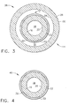
- FIG. 38 Another embodiment of the present invention, in the form of the spaced-apart double wall conduit described in connection with Figures 1 and 2 is shown generally at 38 in the diagrammatic sectional view of Figure 3. That embodiment represents one in which the temperature of fluid in hollow interior 18 and/or the desired temperature of wall outer surface 30 is sufficiently low to enable thermal control in accordance with the present invention through use of a single low emissivity coating 32 on surface 22 of first member 12.
- Such a conduit shown generally at 40 includes a single wall 16, as in first member 12 in Figures 1 - 3, having a single layer low emissivity coating 32 on wall outer surface 22.
- a single wall 16 as in first member 12 in Figures 1 - 3, having a single layer low emissivity coating 32 on wall outer surface 22.
- Such an embodiment can be used in applications to enhance the efficiency of systems in which elevated temperature fluids flow between locations.
- provision of the thin, single layer low emissivity coating according to the present invention on a conduit outer wall surface inhibits emission of thermal energy from such surface and maintains heat within the fluid.
- the conduit wall operates at a higher than normal temperature, requiring selection of a metallic wall material that can withstand such elevated temperature, the efficiency of the system is increased through use of the single layer low emissivity coating according to the present invention.
Landscapes
- Engineering & Computer Science (AREA)
- General Engineering & Computer Science (AREA)
- Mechanical Engineering (AREA)
- Chemically Coating (AREA)
Abstract
Description
- This invention relates to a conduit for the flow of a fluid and, more particularly, to a conduit including a low emissivity coating disposed to inhibit heat transfer through a wall of the conduit.
- Power generating apparatus, for example an aircraft gas turbine engine, as well as various well-known flight vehicles, can be subject during operation to conditions producing undesirable atmospheric icing on components. For example, such icing can occur at and/or within such areas as an engine inlet or engine nacelle, as well as at various external surfaces of the vehicle. To reduce or eliminate such icing conditions, various anti-ice systems have been included in such apparatus.
- In one form, a heated fluid, for example heated air from a turbine engine, is passed through a complex conduit, such as relatively long, spaced-apart double wall tubing including bends about other components, from a heat source to an area adjacent a potential icing site. For more efficient engine operation and use of such heated air, it is desirable to retain the heat in the air within the conduit during passage of the air from the heat source to the potential icing site. In addition, an outer surface of a heated anti-ice conduit potentially can be subject to contact with flammable fluids, one example of which is hydraulic fluid, leaking from another component and having an auto-ignition temperature lower than the temperature of the outer surface of the heated conduit. In that example, should a failure occur in a system adjacent the conduit, flammable fluid contacting an outer surface of an anti-ice conduit at a temperature at or above such auto-ignition temperature can result in a fire within the apparatus.
- One current arrangement to reduce such flammable fluid ignition potential as well as to retain heat within the conduit is to dispose an insulating material about the conduit outer walls and associated supports. However, such insulation is relatively heavy, adding to the total engine weight. This reduces engine efficiency to the extent engine power is required to lift and carry such insulation. In addition, such insulation requires additional assembly time, is relatively expensive, reduces clearances, and is susceptible to field damage.
- Various metallic and non-metallic coatings have been reported for use on external surfaces of components either for enhancing absorption of heat energy or for reflecting such energy from a surface. One type for thermal control surfaces of spacecraft is described in such U.S. Patents as 3,607,338 - Webb and 5,296,285 - Babel et al. Other types relate to hot operating components of turbine engines to reflect heat from an external surface of an article. One typical example is U.S. Patent 5,851,679 - Stowell et al. in which a multi-layer coating is provided on a substrate exposed to combustion gases.
- Provision of a conduit wall with a coating that is very thin, light weight and effectively can inhibit heat transfer through the conduit wall can increase apparatus operating efficiency. In addition such a coating that can be provided on the conduit wall prior to assembly in an apparatus can reduce apparatus assembly time and thereby reduce the cost of the apparatus.
- The present invention, in one embodiment, provides a fluid conduit enclosing a hollow interior for the flow of fluid therein. The fluid conduit comprises a conduit wall of a metal alloy and a single layer metallic coating on a wall outer surface. The conduit wall includes a wall inner surface exposed to the fluid and a wall outer surface having a wall emissivity of at least about 0.4 prior to use. The single layer metallic coating on the wall outer surface is a low emissivity metallic coating having a coating emissivity of less than 0.2 and a coating thickness at least sufficient to provide the coating emissivity and a thickness of no greater than 5000 angstroms.
- Another form of the present invention provides a method for making such a fluid conduit comprising spaced-apart double walls enclosing the hollow interior for the flow of fluid therein. The double wall structure comprises an outer wall having an inner surface and an inner wall having an outer surface. The method comprises assembling a pair of coaxial hollow conduit members disposed with a smaller inner member within and spaced-apart from a larger outer member. An inner surface of the wall of the outer member is maintained in a spaced-apart position from an outer surface of the wall of the inner member to define a gap therebetween. Then the low emissivity coating is deposited on the assembled conduit from within the gap concurrently on the inner surface of the outer member wall and the outer surface of the inner member wall. In one embodiment, the assembled double walled fluid conduit is shaped with bends, prior to depositing the coating, for subsequent assembly about associated apparatus.
- Embodiments of the invention will now be described, by way of example, with reference to the accompanying drawings, in which:
- Figure 1 is a diagrammatic sectional view of one embodiment according to the present invention of a fluid conduit including spaced-apart double walls each having a wall surface defining a gap therebetween, the wall surfaces each including a thin, low emissivity coating.
- Figure 2 is an enlarged, diagrammatic, fragmentary sectional view axially along the conduit of Figure 1.
- Figure 3 is diagrammatic sectional view of another embodiment, as in Figure 1, in which the conduit includes a single low emissivity coating on an outer surface of the wall of an inner member.
- Figure 4 is still another embodiment comprising a single wall conduit structure including a thin, low emissivity coating on an outer surface of the wall.
- Some current commercial forms of aircraft gas turbine engines sometimes are referred to as bypass turbofan engines or, more simply, fan engines. As is widely described in the art, such an engine includes a turbojet as a core of the engine and a duct enclosing a multi-blade fan radially outwardly of and surrounding the core. During engine operation, air is directed to flow through the core as well as through the outer duct. Radially outward of the fan is an engine nacelle that can enclose flammable fluid carrying apparatus as well as long, hollow, appropriately shaped metallic anti-ice conduit or tubing.
- Typically, for safety in containment of heated anti-ice air in aircraft turbine engine applications, such a conduit has been constructed as a shaped, spaced-apart double wall structure with ambient, static air in a gap between inner and outer conduit members. In longer conduits comprising relatively long conduits segments, spacers maintain the members in the spaced-apart relationship. For ease of assembly about other components, a long conduit is provided in shaped segments that are joined during assembly, typically at cooperating flanges. During engine operation, heated air, for example from the engine compressor at a temperature in the range of about 800 - 1200° F, flows through the long, complex shaped conduit hollow interior from the engine to selected engine or nacelle surfaces. Heated fluid in the anti-ice conduit heats such surfaces to avoid detrimental ice formation that can occur under certain low temperature operating conditions.
- In gas turbine engine applications, the walls of the conduit typically are made of a metal having a wall surface emissivity of at least about 0.4 before use and up to about 0.8 or more after operation use as a result of surface oxidation. To conserve heat within such a long, complex shaped conduit and to inhibit emission of heat from the conduit outer surface, it has been a practice to dispose thermal insulation about the conduit and associated hardware after assembly within the engine structure. As discussed above, lifting and carrying the added weight of such insulation during aircraft engine operation is at the expense of engine efficiency. In addition, in the event of a flammable fluid system leak in the vicinity of the anti-ice conduit, flammable fluid having a relatively low auto-ignition temperature, for example as low as about 450° F, can come in contact with the insulation and ignite at the heated surface of the conduit.
- It has been recognized through this invention that the relatively heavy and cumbersome insulation to inhibit heat transfer through a conduit wall can be eliminated. In addition, the structure to avoid such heat transfer or heat emission can be provided during manufacture of the conduit and before its assembly in an engine. The term "emissivity" is used herein in accordance with accepted, well-known heat transfer theory in which emissivity is the ratio of emission of a surface to emission of a black body.
- According to a form of the present invention, provision on a conduit wall outer surface of a low emissivity coating of a selected combination of emissivity and thickness can result, through inhibiting thermal emission from a wall surface, in reduction of the temperature of another surface to below a selected temperature. For example, such selected temperature has been the auto-ignition temperature of a flammable fluid potentially contacting such surface, for example at about 700° F for a typical flammable hydraulic fluid. To accomplish such emission control, the coating has a coating emissivity of less than 0.2, preferably in the range of about 0.05 - 0.1, in combination with a thickness of no greater than 5000 angstroms, preferably in the range of about 1000 - 2000 angstroms. During evaluation of the present invention, it has been recognized that a coating emissivity of less than 0.2 can be achieved with a metal coating based on at least one noble metal such as Pt or Au or their combinations with a thickness in the range of about 1000 - 2000 angstroms. Because such coatings are costly, it is desirable to avoid their thickness being greater than is effective for providing the selected coating emissivity. Therefore, in one form according to the present invention, the low emissivity coating thickness is sufficient to provide a selected coating emissivity of less than 0.2, and for practical purposes no greater than 5000 angstroms. For gas turbine engine applications, it is preferred that the coating be stable at a temperature of at least about 800° F. Current, low emissivity coatings capable of meeting such requirements have been reported, for example coatings based on at least one noble metal, typically Pt or Au or their combination.
- Forms of the present invention will be described in connection with an aircraft gas turbine engine anti-ice conduit in the shape of generally circular cross section tubing. The total extent of such anti-ice tubing or conduit, from heat source to anti-ice heat application location, generally is segmented, joined at flanges and shaped appropriately with bends to pass around other components. One embodiment of the fluid conduit of the present invention especially for aircraft gas turbine engine use is shown generally as radially spaced-apart
double wall conduit 10 in the diagrammatic sectional view of Figure 1.Conduit 10 comprises a first member shown generally at 12 as a circular cross section tube disposed co-axially, radially within, second member shown generally at 14 as another circular cross section tube.First member 12 has anoutside diameter 15. Such double wall structure provides added insurance for containment of fluid withinfirst member 12 in the event of a rupture offirst member 12. In addition, such structure enables provision, in accordance with the present invention, of the external surface temperature ofconduit 10 to be below a selected auto-ignition temperature of a flammable fluid used in apparatus in the vicinity of the conduit. -
First member 12 comprises a metalfirst conduit wall 16 enclosing ahollow interior 18 for the flow of fluid axially therein.First wall 16 includes a first wallinner surface 20 and a first wallouter surface 22.Second member 14, disposed co-axially radially spaced-apart aboutfirst member 12 includes a metalsecond wall 26 having a second wallinner surface 28 and a second wallouter surface 30. Such disposition of the first and second members definesgap 31 therebetween. Typical of current practice, relatively long co-axial double wall conduit members or segments have been maintained spaced apart one from another by thin, ring-like, pronged spacers, one of which is shown in Figure 2. Such spacers are disposed between the members ingap 31 periodically, axially along the conduit length. However, co-axial members in relatively short conduit segments can be maintained spaced apart through joining at member ends, such as at flanges, without the use of spacers. For relatively high temperature applications in a turbine engine in which the fluid inhollow interior 18 is at a relatively high temperature, for example in the range of about 800 - 1200° F as described above, the metal of first andsecond walls - According to the embodiment of the present invention in Figure 1,
outer surface 22 offirst wall 16 andinner surface 28 ofsecond wall 26 each includes, respectively, a thin, single layer low emissivityfirst coating 32 andsecond coating 34 opposed to and facing one another acrossgap 31. In order to retain heat withinhollow interior 18 effectively for typical aircraft gas turbine engine applications by inhibiting the emission of heat fromouter surface 22 offirst wall 16, acrossgap 31, and throughsecond wall 26 to second wallouter surface 30, it was recognized thatsingle layer coatings conduit 10 and be emitted from second wallouter surface 30, heatingouter surface 30 to an undesirable level. With a typical, selected low emissivity coating, for example an available coating based on a noble metal such as Pt and/or Au, it was recognized that a coating thickness in the range of about 1000 - 2000 angstroms was sufficient to contain the heat withinconduit 10. Although a greater coating thickness can be applied, for example up to about 5000 angstroms, such coating can be more costly and not required to achieve the coating emissivity of no greater than 0.2. Because heat from the fluid withinhollow interior 18 is contained inwall 16 by low emissivityfirst coating 32,wall 16 can operate at a temperature higher than it would with known insulation, generally reaching an equilibrium temperature with that of the fluid withinhollow interior 18. As a result, a conduit system in accordance with the present invention transferring heat in a fluid from one point to another can operate at a higher efficiency than a conduit system with known thermal insulation about a conduit outer wall. - Figure 2 is an enlarged, fragmentary, diagrammatic sectional view axially along
conduit 10 of Figure 1. In one type of relatively long assembly in accordance with a method form of the present invention, a plurality of spacers, one of which is shown at 36, is disposed ingap 31 betweensurfaces second coatings spacers 36 during assembly aftercoatings walls spacers 36 when used, such spacers are of thin metal or of a material that resists thermal conduction, for example a material based on a non-metal or ceramic. - During evaluation of the present invention, in one specific example of the embodiment of Figures 1 and 2 in an aircraft gas turbine engine, anti-ice air within
hollow interior 18 was at a temperature of about 1100° F. In addition, flammable hydraulic fluid used in apparatus in the vicinity ofconduit 10, and which potentially could contact second wallouter surface 30 in the event of a hydraulic system leak, had an auto-ignition temperature of about 700° F. Therefore, because it was required in the operational conditions of this example to reduce the temperature ofouter surface 30 to below such auto-ignition temperature, it was found that the combination of low emissivity coatings in juxtaposition across the gap between members in the embodiment of Figures 1 and 2 fulfilled such requirement. - In that example,
walls second members First member 12 had a selected outsidediameter 15 of about 1" andsecond member 14, disposed spaced apart aboutfirst member 12, had a selected inside diameter of about 1.4". During evaluation of the present invention, it was recognized that in an embodiment as in Figures 1 and 2 comprising the radially spaced apart double wall conduit, reflection was to be avoided or minimized between portions ofinner surface 28 ofwall 26.Gap 31 with aradial length 37 of no greater than about 30% of theoutside diameter 15 offirst member 12 was found adequate to inhibit thermal reflection between portions ofinner surface 28 ofwall 26. In this example,radial length 37 ofgap 31 betweenouter surface 22 offirst member 12 andinner surface 28 ofsecond member 14 was selected to be about 0.2", as small as practical based on available commercial tubing to enable assembly of the conduit.Such length 37 was less than 30% ofoutside diameter 15 offirst member 12 and within a preferred range of about 0.1 - 0.25". - During one evaluation, first and
second coatings surfaces Coatings - In this evaluation, with the fluid temperature within hollow interior at about 1100° F, it was found that the combination of juxtaposed,
single layer coatings gap 31 both were required withgap 31 to reduce the temperature ofouter surface 30 to below the auto-ignition temperature of about 700° F. In such combination, coating 32 onouter surface 22 offirst member wall 16 retained heat withinwall 16. Any thermal energy emitted from coatingsurface 33 ofcoating 32 passed acrossgap 31 and was reflected byouter surface 35 ofsecond coating 34 towardfirst member 12. In effect,second coating 34 providedgap 31 with a low emissivity coating. Thus thermal energy was inhibited from penetratingwall 26 ofsecond member 14 in an amount sufficient to increase in the temperature ofouter surface 30 ofsecond wall 26 to an undesirable amount, in this example 700° F. - According to a method form of the present invention, a pair of uncoated first and
second members sized spacers 36 were disposed aboutouter surface 22 offirst member 12 prior to assembly to maintaingap 31 between the members. Then smaller diameterfirst member 12 was secured, for example by brazing within and spaced-apart from larger diametersecond member 14 to definegap 31 therebetween. Such assembly represented a conduit segment of a fluid conduit of greater length defined by a plurality of shaped segments joined at juxtaposed flanges. After such assembly, the preform was shaped into a conduit segment with at least one and typically with several bends, some at relatively sharp angles, appropriately for its location in the final conduit according to a predetermined design to pass about other engine or aircraft components. - After shaping, the conduit segment was cleaned with solvent to remove surface contaminants. Then a liquid carrying predominantly platinum acetylacetone as the coating element was disposed within
gap 31 to contact and deposit a coating precursor film onsurfaces surfaces - This provided Pt-base single layer
low emissivity coatings surfaces - Another embodiment of the present invention, in the form of the spaced-apart double wall conduit described in connection with Figures 1 and 2 is shown generally at 38 in the diagrammatic sectional view of Figure 3. That embodiment represents one in which the temperature of fluid in
hollow interior 18 and/or the desired temperature of wallouter surface 30 is sufficiently low to enable thermal control in accordance with the present invention through use of a singlelow emissivity coating 32 onsurface 22 offirst member 12. - Another embodiment of the present invention is shown in the diagrammatic sectional view of Figure 4. Such a conduit shown generally at 40 includes a
single wall 16, as infirst member 12 in Figures 1 - 3, having a single layerlow emissivity coating 32 on wallouter surface 22. Such an embodiment can be used in applications to enhance the efficiency of systems in which elevated temperature fluids flow between locations. As was mentioned above, provision of the thin, single layer low emissivity coating according to the present invention on a conduit outer wall surface inhibits emission of thermal energy from such surface and maintains heat within the fluid. Although, the conduit wall operates at a higher than normal temperature, requiring selection of a metallic wall material that can withstand such elevated temperature, the efficiency of the system is increased through use of the single layer low emissivity coating according to the present invention. - For completeness, various aspects of the invention are set out in the following numbered clauses:
- 1. A multiple spaced-apart wall fluid conduit (10) enclosing a hollow interior (18) for the flow of a fluid therein, comprising:
- a metal first conduit wall (16) having a radially inner first surface (20) enclosing the hollow interior (18) and a radially outer second surface (22); and,
- a metal second conduit wall (26) spaced apart radially outwardly from the first conduit wall (16) and having a radially inner third surface (28) spaced apart radially in juxtaposition with the outer second surface (22) of the first wall (16) to define a gap (31) therebetween, wherein:
- the first conduit wall (16) includes on the outer second surface (22) a single layer first low emissivity metal coating (32), and the second conduit wall (26) includes on the inner third surface (28) a single layer second low emissivity metal coating (34);
- the first and second low emissivity coatings (32,34) each having a coating emissivity of less than 0.2 and a coating thickness at least sufficient to provide the coating emissivity.
- 2. The fluid conduit (10) of clause 1 in which the coating thickness is no greater than 5000 angstroms.
- 3. The fluid conduit (10) of clause 2 in which each of the first and second coatings (32,34) has:
- a coating emissivity in the range of about 0.05 - 0.1; and,
- a coating thickness in the range of about 1000 - 2000 angstroms.
- 4. The fluid conduit (10) of clause 1 in which:
- the first conduit wall (16) defines an inner first member (12) of substantially circular cross section and having a first member outside diameter (15);
- the second conduit wall (26) defines an outer second member (14) of substantially circular cross section disposed radially outwardly about the first member (12) and spaced apart from the first member (12) across the gap (31);
- the gap (31) having a radial gap length (37) of no greater than about 30% of the first member outside diameter (15).
- 5. The fluid conduit (10) of clause 4 in which the gap (31) has a radial length (37) of less than 0.3 inches.
- 6. he fluid conduit (10) of clause 5 in which the gap (31) has a radial length (37) in the range of about 0.1 - 0.25 inches.
- 7. The fluid conduit (10) of clause 4 in the form of an aircraft gas turbine engine anti-ice conduit segment, in which:
- the first conduit wall (16) and the second conduit wall (26) each has an emissivity of at least about 0.4 prior to use and is made of a metal alloy based on at least one element selected from the group consisting of Fe, Co, and Ni and capable of withstanding the flow of the fluid at a temperature of at least about 800° F; and,
- the first and second low emissivity coatings (32,34) each is based on an element selected from the group consisting of Pt, Au, and their combinations.
- 8. The fluid conduit (10) of clause 7 in which:
- the coating emissivity of each of the first and second coatings (32,34) is in the range of about 0.05 - 0.1;
- the gap radial length (37) is in the range of about 0.1 - 0.25 inches; and,
- the thickness of each of the first and second coatings (32,34) is in the range of about 1000 - 2000 angstroms.
- 9. A multiple spaced-apart wall fluid conduit (38) enclosing a hollow interior (18) for the flow of fluid therein, comprising:
- a metal first conduit wall (16) having a radially inner first surface (20) enclosing the hollow interior (18) and a radially outer second surface (22); and,
- a metal second conduit wall conduit wall (26) spaced apart radially outwardly from the first conduit wall (16) and having a radially inner third surface (28) spaced apart radially in juxtaposition with the outer second surface (22) of the first wall (16) to define a gap (31) therebetween, wherein:
- the first conduit wall (16) includes on the outer second surface (22) a single layer low emissivity metal coating (32);
- the low emissivity coating (32) having a coating emissivity of less than 0.2 and a coating thickness at least sufficient to provide the coating emissivity.
- 10. The fluid conduit (38) of clause 9 in which the coating thickness is no greater than 5000 angstroms.
- 11. The fluid conduit (38) of
clause 10 in which the low emissivity coating has:- a coating emissivity in the range of about 0.05 - 0.1; and,
- a coating thickness in the range of about 1000 - 2000 angstroms.
- 12. The fluid conduit (38) of clause 9 in which:
- the first conduit wall (16) defines an inner first member (12) of substantially circular cross section and having a first member outside diameter (15);
- the second conduit wall (26) defines an outer second member (14) of substantially circular cross section disposed radially outwardly about the first member (12) and spaced apart from the first member (12) across the gap (31);
- the gap (31) having a radial gap length (37) of no greater than about 30% of the first member outside diameter (15).
- 13. The fluid conduit (38) of
clause 12 in which the gap (31) has a radial length (37) of less than 0.3 inches. - 14. The fluid conduit (38) of clause 13 in which the gap (31) has a radial length (37) in the range of about 0.1 - 0.25 inches.
- 15. The fluid conduit (38) of clause 9 in which:
- the first and second conduit walls (16, 26) each is made of metal alloy based on at least one element selected from the group consisting of Fe, Co, and Ni; and,
- the low emissivity coating (32) is based on an element selected from the group consisting of Pt, Au, and their combinations.
- 16. The fluid conduit (38) of
clause 15 in which:- the coating emissivity is in the range of about 0.05 - 0.1;
- the gap radial length (37) is in the range of about 0.1 - 0.25 inches; and,
- the coating thickness is in the range of about 1000 - 2000 angstroms.
- 17. A fluid conduit (40) comprising a metal fluid conduit wall (16) enclosing a hollow interior (18) for the flow of a fluid therein, the fluid conduit wall (16) having a radially inner surface (20) enclosing the hollow interior (18) and a radially outer surface (22); wherein,
the radially outer surface (22) includes a single layer metal low emissivity coating (32) having a coating emissivity of less than 0.2 and a coating thickness at least sufficient to provide the coating emissivity. - 18. The fluid conduit (40) of clause 17 in which the coating thickness is no greater than 5000 angstroms.
- 19. The fluid conduit (40) of
clause 18 in which the coating (32) has:- a coating emissivity in the range of about 0.05 - 0.1; and,
- a coating thickness in the range of about 1000 - 2000 angstroms.
- 20. The fluid conduit (40) of clause 17 in which:
- the conduit wall (16) is made of metal alloy based on at least one element selected from the group consisting of Fe, Co, and Ni; and,
- the low emissivity coating (32) is based on an element selected from the group consisting of Pt, Au, and their combinations.
- 21. A method for making a multiple spaced-apart wall fluid conduit (10) enclosing a hollow interior (18) for the flow of fluid therein, comprising:
- providing a first conduit member (12) having a metal first wall (!6) including a radially inner first surface (20) defining the hollow interior (18) and a radially outer second surface (22) of a first radial diameter (15), and a second conduit member (14) having a metal second wall (26) including a radially inner third surface (28) of a second radial diameter greater than the first radial diameter (15);
- assembling the first conduit member (12) co-axially with and radially within the second conduit member (14) to provide an assembly with the outer first surface (20) of the first member (12) maintained radially spaced-apart from the inner third surface (28) of the second member (14) to define a gap (31) therebetween; and then,
- depositing a low emissivity coating (32,34) concurrently on each of the radially outer first surface (22) of the first member (12) and the radially inner third surface (28) of the second member (14) from within the gap (31).
- 22. The method of clause 21 in which, after providing the assembly of the first and second conduit members (12,14) and before depositing the coating (32,34), the assembly is shaped with bends for assembly about associated apparatus.
- 23. The method of clause 21 in which the low emissivity coating (32,34) is deposited by reactive vaporization to a thickness of no greater than 5000 angstroms.
- 24. The method of clause 23 in which the coating (32,34) is deposited from a metal compound based on an element selected from the group consisting of Pt, Au, and their combinations.
Claims (10)
- A multiple spaced-apart wall fluid conduit (10) enclosing a hollow interior (18) for the flow of a fluid therein, comprising:a metal first conduit wall (16) having a radially inner first surface (20) enclosing the hollow interior (18) and a radially outer second surface (22); and,a metal second conduit wall (26) spaced apart radially outwardly from the first conduit wall (16) and having a radially inner third surface (28) spaced apart radially in juxtaposition with the outer second surface (22) of the first wall (16) to define a gap (31) therebetween, wherein:the first conduit wall (16) includes on the outer second surface (22) a single layer first low emissivity metal coating (32), and the second conduit wall (26) includes on the inner third surface (28) a single layer second low emissivity metal coating (34);the first and second low emissivity coatings (32,34) each having a coating emissivity of less than 0.2 and a coating thickness at least sufficient to provide the coating emissivity.
- The fluid conduit (10) of claim 1 in which the coating thickness is no greater than 5000 angstroms.
- The fluid conduit (10) of claim 1 in which:the first conduit wall (16) defines an inner first member (12) of substantially circular cross section and having a first member outside diameter (15);the second conduit wall (26) defines an outer second member (14) of substantially circular cross section disposed radially outwardly about the first member (12) and spaced apart from the first member (12) across the gap (31);the gap (31) having a radial gap length (37) of no greater than about 30% of the first member outside diameter (15).
- The fluid conduit (10) of claim 3 in the form of an aircraft gas turbine engine anti-ice conduit segment, in which:the first conduit wall (16) and the second conduit wall (26) each has an emissivity of at least about 0.4 prior to use and is made of a metal alloy based on at least one element selected from the group consisting of Fe, Co, and Ni and capable of withstanding the flow of the fluid at a temperature of at least about 800° F; and,the first and second low emissivity coatings (32,34) each is based on an element selected from the group consisting of Pt, Au, and their combinations.
- A multiple spaced-apart wall fluid conduit (38) enclosing a hollow interior (18) for the flow of fluid therein, comprising:a metal first conduit wall (16) having a radially inner first surface (20) enclosing the hollow interior (18) and a radially outer second surface (22); and,a metal second conduit wall conduit wall (26) spaced apart radially outwardly from the first conduit wall (16) and having a radially inner third surface (28) spaced apart radially in juxtaposition with the outer second surface (22) of the first wall (16) to define a gap (31) therebetween, wherein:the first conduit wall (16) includes on the outer second surface (22) a single layer low emissivity metal coating (32);the low emissivity coating (32) having a coating emissivity of less than 0.2 and a coating thickness at least sufficient to provide the coating emissivity.
- The fluid conduit (38) of claim 5 in which the coating thickness is no greater than 5000 angstroms.
- The fluid conduit (38) of claim 5 in which:the first conduit wall (16) defines an inner first member (12) of substantially circular cross section and having a first member outside diameter (15);the second conduit wall (26) defines an outer second member (14) of substantially circular cross section disposed radially outwardly about the first member (12) and spaced apart from the first member (12) across the gap (31);the gap (31) having a radial gap length (37) of no greater than about 30% of the first member outside diameter (15).
- The fluid conduit (38) of claim 5 in which:the first and second conduit walls (16, 26) each is made of metal alloy based on at least one element selected from the group consisting of Fe, Co, and Ni; and,the low emissivity coating (32) is based on an element selected from the group consisting of Pt, Au, and their combinations.
- A method for making a multiple spaced-apart wall fluid conduit (10) enclosing a hollow interior (18) for the flow of fluid therein, comprising:providing a first conduit member (12) having a metal first wall (!6) including a radially inner first surface (20) defining the hollow interior (18) and a radially outer second surface (22) of a first radial diameter (15), and a second conduit member (14) having a metal second wall (26) including a radially inner third surface (28) of a second radial diameter greater than the first radial diameter (15);assembling the first conduit member (12) co-axially with and radially within the second conduit member (14) to provide an assembly with the outer first surface (20) of the first member (12) maintained radially spaced-apart from the inner third surface (28) of the second member (14) to define a gap (31) therebetween; and then,depositing a low emissivity coating (32,34) concurrently on each of the radially outer first surface (22) of the first member (12) and the radially inner third surface (28) of the second member (14) from within the gap (31).
- The method of claim 9 in which the low emissivity coating (32,34) is deposited by reactive vaporization to a thickness of no greater than 5000 angstroms.
Priority Applications (2)
| Application Number | Priority Date | Filing Date | Title |
|---|---|---|---|
| EP20040257586 EP1666784B1 (en) | 2004-12-06 | 2004-12-06 | Fluid conduit wall inhibiting heat transfer and method for making |
| DE200460019664 DE602004019664D1 (en) | 2004-12-06 | 2004-12-06 | Thermal conduction preventing fluid line wall and manufacturing process |
Applications Claiming Priority (1)
| Application Number | Priority Date | Filing Date | Title |
|---|---|---|---|
| EP20040257586 EP1666784B1 (en) | 2004-12-06 | 2004-12-06 | Fluid conduit wall inhibiting heat transfer and method for making |
Publications (2)
| Publication Number | Publication Date |
|---|---|
| EP1666784A1 true EP1666784A1 (en) | 2006-06-07 |
| EP1666784B1 EP1666784B1 (en) | 2009-02-25 |
Family
ID=34930888
Family Applications (1)
| Application Number | Title | Priority Date | Filing Date |
|---|---|---|---|
| EP20040257586 Expired - Lifetime EP1666784B1 (en) | 2004-12-06 | 2004-12-06 | Fluid conduit wall inhibiting heat transfer and method for making |
Country Status (2)
| Country | Link |
|---|---|
| EP (1) | EP1666784B1 (en) |
| DE (1) | DE602004019664D1 (en) |
Cited By (3)
| Publication number | Priority date | Publication date | Assignee | Title |
|---|---|---|---|---|
| WO2008015361A1 (en) * | 2006-08-04 | 2008-02-07 | Airbus France | Aircraft conduit |
| EP2354472A4 (en) * | 2008-11-27 | 2012-06-06 | Toshiba Kk | STEAM APPARATUS |
| WO2017024301A1 (en) * | 2015-08-06 | 2017-02-09 | Flexible Technologies, Inc. | Insulated duct with air gap and method of use |
Citations (6)
| Publication number | Priority date | Publication date | Assignee | Title |
|---|---|---|---|---|
| US4139024A (en) * | 1971-07-29 | 1979-02-13 | General Electric Company | Thermal insulation structure |
| US5658614A (en) * | 1994-10-28 | 1997-08-19 | Howmet Research Corporation | Platinum aluminide CVD coating method |
| US5851679A (en) * | 1996-12-17 | 1998-12-22 | General Electric Company | Multilayer dielectric stack coated part for contact with combustion gases |
| JP2000028078A (en) * | 1998-07-08 | 2000-01-25 | Ichimura Sanso Kk | Radiation heat reflecting sheet |
| US6207299B1 (en) * | 1996-10-10 | 2001-03-27 | Sollac | Sheet metal with an aluminum-containing coating having low emissivity |
| US20030075226A1 (en) * | 2000-01-07 | 2003-04-24 | Russell Codling | Insulated pipework system |
-
2004
- 2004-12-06 EP EP20040257586 patent/EP1666784B1/en not_active Expired - Lifetime
- 2004-12-06 DE DE200460019664 patent/DE602004019664D1/en not_active Expired - Lifetime
Patent Citations (6)
| Publication number | Priority date | Publication date | Assignee | Title |
|---|---|---|---|---|
| US4139024A (en) * | 1971-07-29 | 1979-02-13 | General Electric Company | Thermal insulation structure |
| US5658614A (en) * | 1994-10-28 | 1997-08-19 | Howmet Research Corporation | Platinum aluminide CVD coating method |
| US6207299B1 (en) * | 1996-10-10 | 2001-03-27 | Sollac | Sheet metal with an aluminum-containing coating having low emissivity |
| US5851679A (en) * | 1996-12-17 | 1998-12-22 | General Electric Company | Multilayer dielectric stack coated part for contact with combustion gases |
| JP2000028078A (en) * | 1998-07-08 | 2000-01-25 | Ichimura Sanso Kk | Radiation heat reflecting sheet |
| US20030075226A1 (en) * | 2000-01-07 | 2003-04-24 | Russell Codling | Insulated pipework system |
Non-Patent Citations (1)
| Title |
|---|
| PATENT ABSTRACTS OF JAPAN vol. 2000, no. 04 31 August 2000 (2000-08-31) * |
Cited By (8)
| Publication number | Priority date | Publication date | Assignee | Title |
|---|---|---|---|---|
| WO2008015361A1 (en) * | 2006-08-04 | 2008-02-07 | Airbus France | Aircraft conduit |
| FR2904677A1 (en) * | 2006-08-04 | 2008-02-08 | Airbus France Sas | AIRCRAFT CONDUIT |
| US7757719B2 (en) | 2006-08-04 | 2010-07-20 | Airbus France | Aircraft conduit |
| RU2442060C2 (en) * | 2006-08-04 | 2012-02-10 | Эрбюс Операсьон (Сас) | Aircraft pipeline |
| CN101553681B (en) * | 2006-08-04 | 2012-08-01 | 空中客车运营简化股份公司 | Aircraft conduit |
| EP2354472A4 (en) * | 2008-11-27 | 2012-06-06 | Toshiba Kk | STEAM APPARATUS |
| WO2017024301A1 (en) * | 2015-08-06 | 2017-02-09 | Flexible Technologies, Inc. | Insulated duct with air gap and method of use |
| US10295218B2 (en) | 2015-08-06 | 2019-05-21 | Flexible Technologies, Inc. | Insulated duct with air gap and method of use |
Also Published As
| Publication number | Publication date |
|---|---|
| DE602004019664D1 (en) | 2009-04-09 |
| EP1666784B1 (en) | 2009-02-25 |
Similar Documents
| Publication | Publication Date | Title |
|---|---|---|
| US6854487B2 (en) | Fluid conduit wall inhibiting heat transfer and method for making | |
| US20230073446A1 (en) | Hpc and hpt disks coated by atomic layer deposition | |
| CN106150569B (en) | System for turbine shroud to be thermally isolated | |
| US20050048305A1 (en) | Optical reflector for reducing radiation heat transfer to hot engine parts | |
| CN1740641A (en) | Combustor member and method for making a combustor assembly | |
| EP3577321B1 (en) | Coated flange bolt hole and methods of forming the same | |
| JP2004218639A (en) | Improved high-temperature turbine nozzle with reduced temperature due to optical reflection and method of manufacturing the same | |
| EP1435490B1 (en) | High temperature centerbody and process for manufacturing | |
| US20190284940A1 (en) | Turbine airfoil with internals coated by atomic layer deposition | |
| US10738648B2 (en) | Graphene discs and bores and methods of preparing the same | |
| EP1666784B1 (en) | Fluid conduit wall inhibiting heat transfer and method for making | |
| IE55883B1 (en) | Varying thickness thermal barrier for combustion turbine baskets | |
| US6884524B2 (en) | Low cost chrome and chrome/aluminide process for moderate temperature applications | |
| JP2977369B2 (en) | Moving and stationary blade surface layer | |
| US11225907B2 (en) | Gas turbine engine pipe cover | |
| US6884461B2 (en) | Turbine nozzle with heat rejection coats | |
| CA3001802A1 (en) | Thermal coating system with aluminide | |
| US7094446B2 (en) | Method for applying a coating system including a heat rejection layer to a substrate surface of a component | |
| EP3285005A2 (en) | Systems and methods for combustor panel of a gas turbine | |
| CN116752071A (en) | A low thermal conductivity, high reflectivity composite coating and preparation method | |
| US6893737B2 (en) | Low cost aluminide process for moderate temperature applications | |
| EP3693489B1 (en) | A combustor wall with bond coat layer and layer of networked ceramic nanofibers | |
| US20210348761A1 (en) | Panel burn through tolerant shell design | |
| Stickles et al. | Innovative high-temperature aircraft engine fuel nozzle design | |
| US20090317243A1 (en) | High reflectivity infrared coating applications for use in hirss applications |
Legal Events
| Date | Code | Title | Description |
|---|---|---|---|
| PUAI | Public reference made under article 153(3) epc to a published international application that has entered the european phase |
Free format text: ORIGINAL CODE: 0009012 |
|
| AK | Designated contracting states |
Kind code of ref document: A1 Designated state(s): AT BE BG CH CY CZ DE DK EE ES FI FR GB GR HU IE IS IT LI LT LU MC NL PL PT RO SE SI SK TR |
|
| AX | Request for extension of the european patent |
Extension state: AL BA HR LV MK YU |
|
| 17P | Request for examination filed |
Effective date: 20061207 |
|
| 17Q | First examination report despatched |
Effective date: 20070112 |
|
| AKX | Designation fees paid |
Designated state(s): DE FR GB |
|
| GRAP | Despatch of communication of intention to grant a patent |
Free format text: ORIGINAL CODE: EPIDOSNIGR1 |
|
| GRAS | Grant fee paid |
Free format text: ORIGINAL CODE: EPIDOSNIGR3 |
|
| GRAA | (expected) grant |
Free format text: ORIGINAL CODE: 0009210 |
|
| AK | Designated contracting states |
Kind code of ref document: B1 Designated state(s): DE FR GB |
|
| REG | Reference to a national code |
Ref country code: GB Ref legal event code: FG4D |
|
| REF | Corresponds to: |
Ref document number: 602004019664 Country of ref document: DE Date of ref document: 20090409 Kind code of ref document: P |
|
| PLBE | No opposition filed within time limit |
Free format text: ORIGINAL CODE: 0009261 |
|
| STAA | Information on the status of an ep patent application or granted ep patent |
Free format text: STATUS: NO OPPOSITION FILED WITHIN TIME LIMIT |
|
| 26N | No opposition filed |
Effective date: 20091126 |
|
| REG | Reference to a national code |
Ref country code: FR Ref legal event code: PLFP Year of fee payment: 12 |
|
| REG | Reference to a national code |
Ref country code: FR Ref legal event code: PLFP Year of fee payment: 13 |
|
| PGFP | Annual fee paid to national office [announced via postgrant information from national office to epo] |
Ref country code: GB Payment date: 20161228 Year of fee payment: 13 |
|
| PGFP | Annual fee paid to national office [announced via postgrant information from national office to epo] |
Ref country code: FR Payment date: 20161227 Year of fee payment: 13 |
|
| PGFP | Annual fee paid to national office [announced via postgrant information from national office to epo] |
Ref country code: DE Payment date: 20161229 Year of fee payment: 13 |
|
| REG | Reference to a national code |
Ref country code: DE Ref legal event code: R119 Ref document number: 602004019664 Country of ref document: DE |
|
| GBPC | Gb: european patent ceased through non-payment of renewal fee |
Effective date: 20171206 |
|
| REG | Reference to a national code |
Ref country code: FR Ref legal event code: ST Effective date: 20180831 |
|
| PG25 | Lapsed in a contracting state [announced via postgrant information from national office to epo] |
Ref country code: FR Free format text: LAPSE BECAUSE OF NON-PAYMENT OF DUE FEES Effective date: 20180102 Ref country code: DE Free format text: LAPSE BECAUSE OF NON-PAYMENT OF DUE FEES Effective date: 20180703 |
|
| PG25 | Lapsed in a contracting state [announced via postgrant information from national office to epo] |
Ref country code: GB Free format text: LAPSE BECAUSE OF NON-PAYMENT OF DUE FEES Effective date: 20171206 |