EP1666697A1 - Fluid operated pump for use in a wellbore - Google Patents
Fluid operated pump for use in a wellbore Download PDFInfo
- Publication number
- EP1666697A1 EP1666697A1 EP06110792A EP06110792A EP1666697A1 EP 1666697 A1 EP1666697 A1 EP 1666697A1 EP 06110792 A EP06110792 A EP 06110792A EP 06110792 A EP06110792 A EP 06110792A EP 1666697 A1 EP1666697 A1 EP 1666697A1
- Authority
- EP
- European Patent Office
- Prior art keywords
- bore
- valve assembly
- fluid
- housing
- pump
- Prior art date
- Legal status (The legal status is an assumption and is not a legal conclusion. Google has not performed a legal analysis and makes no representation as to the accuracy of the status listed.)
- Granted
Links
- 239000012530 fluid Substances 0.000 title claims abstract description 78
- 238000005086 pumping Methods 0.000 claims abstract description 9
- 238000000034 method Methods 0.000 claims description 12
- 230000015572 biosynthetic process Effects 0.000 claims description 6
- 238000003780 insertion Methods 0.000 claims description 6
- 230000037431 insertion Effects 0.000 claims description 6
- 230000013011 mating Effects 0.000 claims description 6
- 238000004519 manufacturing process Methods 0.000 claims description 5
- 230000014759 maintenance of location Effects 0.000 claims description 4
- 238000009825 accumulation Methods 0.000 claims description 3
- 230000000717 retained effect Effects 0.000 abstract description 2
- 238000005755 formation reaction Methods 0.000 description 5
- 238000002347 injection Methods 0.000 description 4
- 239000007924 injection Substances 0.000 description 4
- 238000004891 communication Methods 0.000 description 3
- 230000004888 barrier function Effects 0.000 description 2
- 229930195733 hydrocarbon Natural products 0.000 description 2
- 238000013022 venting Methods 0.000 description 2
- 241000251468 Actinopterygii Species 0.000 description 1
- 239000004215 Carbon black (E152) Substances 0.000 description 1
- 229910000831 Steel Inorganic materials 0.000 description 1
- 230000000712 assembly Effects 0.000 description 1
- 238000000429 assembly Methods 0.000 description 1
- 239000004020 conductor Substances 0.000 description 1
- 239000000835 fiber Substances 0.000 description 1
- 150000002430 hydrocarbons Chemical class 0.000 description 1
- 125000001183 hydrocarbyl group Chemical group 0.000 description 1
- 238000009434 installation Methods 0.000 description 1
- 238000002955 isolation Methods 0.000 description 1
- 238000007789 sealing Methods 0.000 description 1
- 239000010959 steel Substances 0.000 description 1
Images



Classifications
-
- F—MECHANICAL ENGINEERING; LIGHTING; HEATING; WEAPONS; BLASTING
- F04—POSITIVE - DISPLACEMENT MACHINES FOR LIQUIDS; PUMPS FOR LIQUIDS OR ELASTIC FLUIDS
- F04B—POSITIVE-DISPLACEMENT MACHINES FOR LIQUIDS; PUMPS
- F04B47/00—Pumps or pumping installations specially adapted for raising fluids from great depths, e.g. well pumps
- F04B47/06—Pumps or pumping installations specially adapted for raising fluids from great depths, e.g. well pumps having motor-pump units situated at great depth
- F04B47/08—Pumps or pumping installations specially adapted for raising fluids from great depths, e.g. well pumps having motor-pump units situated at great depth the motors being actuated by fluid
-
- E—FIXED CONSTRUCTIONS
- E21—EARTH OR ROCK DRILLING; MINING
- E21B—EARTH OR ROCK DRILLING; OBTAINING OIL, GAS, WATER, SOLUBLE OR MELTABLE MATERIALS OR A SLURRY OF MINERALS FROM WELLS
- E21B43/00—Methods or apparatus for obtaining oil, gas, water, soluble or meltable materials or a slurry of minerals from wells
- E21B43/12—Methods or apparatus for controlling the flow of the obtained fluid to or in wells
- E21B43/121—Lifting well fluids
- E21B43/129—Adaptations of down-hole pump systems powered by fluid supplied from outside the borehole
Definitions
- the present invention relates to a fluid operated pump for use in a wellbore.
- Oil and gas wells include a wellbore formed in the earth to access hydrocarbon-bearing formations.
- a borehole is initially formed and thereafter the borehole is lined with steel pipe, or casing in order to prevent cave in and facilitate the isolation of portions of the wellbore.
- steel pipe, or casing is lined with steel pipe, or casing in order to prevent cave in and facilitate the isolation of portions of the wellbore.
- at least one area of the wellbore casing is perforated to form a fluid path for the hydrocarbons to enter the wellbore.
- natural formation pressure is adequate to bring production fluid to the surface for collection. More commonly however, some form of artificial lift is necessary to retrieve the fluid.
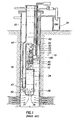
- FIG. 1 is a section view of a wellbore with a gas operated pump disposed therein.
- the pump 30 is located adjacent perforations in the wellbore 10.
- the pump operates with pressured gas injected from a high pressure gas vessel 24 into a gas supply line 80 to a valve assembly 40 disposed in a body of the pump 30.
- the valve assembly 40 consists of an injection control valve 70 for controlling the input of gas into an accumulation chamber 34 and a vent control valve 90 for controlling the venting of valve assemblies for a gas operated pump have an internal bypass passageway for injecting gas into the chamber.
- the internal bypass passageway must be a large enough diameter to facilitate a correct amount of gas flow into the chamber.
- US Patent 2336683 Hatfield discloses a method and apparatus for pumping well fluid from a well utilising gas as the lifting medium.
- a valve assembly is insertable on the end of a macaroni through well tubing into a seating member, and the valve assembly is then actuable by a weight bar that is lowered through the macaroni on the end of a wireline.
- the valve assembly can be subsequently withdrawn from the well to enable it to be replaced.
- a fluid operated pump for use in a wellbore, the pump comprising a housing with at least one longitudinal bore therethrough; a first fluid path formed in the housing and opening into the bore for communicating a pressurized fluid from the bore to an area below the housing; a second fluid path formed in the housing and opening into the bore for communicating an exhaust fluid from an area below the housing to the exterior of the housing; and a removable valve assembly axially insertable into the bore of the housing and having ports that are constructed and arranged in an outer valve surface to communicate with the first and second fluid paths when the valve assembly is inserted into the bore and to selectively direct the pressurized fluid and the exhaust fluid; characterised in that fluid actuating means is providing for communicating motive fluid to the bore in order to operate the valve assembly within the bore.
- the invention also provides a method of operating a fluid operated pump within a wellbore, the method utilizing a removable valve assembly within a longitudinal bore in a housing of the pump, wherein a first fluid path in the housing opening into the bore is provided for supply of pressurized fluid from the bore to an area of the pump below the housing, and a second fluid path in the housing opening into the bore is provided for an exhaust fluid from an area below the housing to the exterior of the housing, the method comprising lowering the valve assembly to a location in the wellbore proximate the bore in the housing; aligning the valve assembly with the bore; axially inserting the valve assembly into the bore such that ports in an outer valve surface communicate with the first and second fluid paths; and sealingly retaining the valve assembly in the bore during pumping of fluid by the pump; characterised in that the valve assembly is operated within the bore by motive fluid supplied to the bore by fluid actuating means.
- FIG. 2 is a sectional view through a housing 200 of a gas operated pump in accordance with a preferred embodiment of the invention.
- the housing 200 includes two longitudinal bores 215, 225 as well as a number of internally formed motive fluid paths to operate a valve and to direct gas through the pump. More particularly the housing 200 includes an internally threaded portion 205 at its upper end for connection to a string of tubulars (not shown) and an externally threaded portion 210 at its lower end for connection to an accumulator chamber (not shown).
- the housing 200 has a first longitudinal bore 215 therethrough having an internally threaded portion 220 at its lower end for connection to a diptube (not shown). In use, the bore 215 serves as a conduit for production fluid pumped towards the surface of the well.
- the housing 200 also has a second longitudinal bore 225.
- An aperture 235 formed in a wall of the housing 200 provides communication between the second longitudinal bore 225 and the exterior of the housing 200.
- a third bore 230 provides communication between an injection port 250 in the wall of the second longitudinal bore 225 and the lower end of the housing 200 for injection of pressurized gas into the accumulation chamber (not shown).
- the second longitudinal bore 225 further includes a first profile 240 and a second profile 245 formed within the bore 225 to receive a removable valve assembly (not shown) that is insertable in the upper end 255 of bore 225.
- the profiles 240, 245 are continuous grooves and are formed to permit mating formations of the valve assembly to mate therewith as will be more fully described herebelow.
- Figure 3 illustrates the removable valve assembly 300 disposed on the end of a coiled tubing string 325 for insertion into the housing 200 of Figure 2.
- the removable valve assembly 300 includes an inlet control valve 305, a vent control valve 310, a valve stem 315 and an actuator 320.
- the valve stem 315 is connected to both the inlet control valve 305 and the vent control valve 310.
- the actuator 320 moves the valve stem 315, alternatively opening and closing the inlet control valve 305 and the vent control valve 310.
- gas flows down the coiled tubing string 325 into the assembly 300 and out through a gas outlet port 330.
- vent control valve 310 when the vent control valve 310 is in the open position, gas enters a vent inlet port 340 and exits through a vent outlet port 335.
- a first control conduit 345 and a second control conduit 350 are housed inside the coiled tubing string 325.
- the first control conduit 345 and the second control conduit 350 are typically hydraulic control lines and are used to actuate the valve assembly 300.
- electrical power can be transmitted through the one or more of the control conduits 345, 350 to actuate the valve assembly 300.
- the valve assembly 300 may include data transmitting means to transmit data, such as pressure and temperature within the pump chamber, through the control conduits 345, 350 to the surface of the wellbore.
- the valve assembly 300 or the housing 200 may include sensors.
- the transmitting means can include fiber optic cable.
- a first seal 355, second seal 360, and third seal 365 are circumferentially mounted around an external surface of the valve assembly 300.
- the purpose of the seals is to isolate fluid paths between the valve assembly 300 and the housing 200 ( Figure 2) when the valve assembly 300 is inserted therein.
- the assembly 300 further includes a first key 370 and a second key 375 to secure the valve assembly 300 axially within the housing 200.
- the first key 370 and the second key 375 are outwardly biased and are designed to mate with the profiles in the interior surface of the housing 200 ( Figure 2).
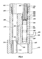
- FIG 4 is a sectional view of the valve assembly 300 disposed in the housing 200.
- the valve assembly 300 is shown at the end of the coiled tubing string 325 that provides a source of pressurized gas to operate the pump.
- the accumulator chamber 415 for collecting formation fluid is secured to the housing 200 by the externally threaded portion 210 at the lower end of the housing 200.
- the tubing string 405 is secured to the housing 200 at the internally threaded portion 205.
- a diptube 410 is secured to the housing 200 by way of the internally threaded portion 220 of the first longitudinal bore 215.
- a vent line 420 is secured to the housing 200 at the aperture 235 to provide a passageway for gas venting from the accumulator chamber 415.
- the removable valve assembly 300 is installed at an end of the coiled tubing string 325 and the string 325 is inserted in tubing string 405 at the top of the wellbore and the valve assembly 300 is lowered on the string 325 towards the housing 200.
- a profile means and guide orient and align the valve assembly 300 with the second longitudinal bore 225 which is offset from the center of the housing 200.
- Profile means and guides are well known in the art and typically include some mechanical means for orienting a device in a wellbore.
- the valve assembly 300 After insertion into the upper end 255 of the bore 225, the valve assembly 300 is urged downwards until the first key 370 and the second key 375 of the valve assembly 300 are secured in place in the first profile 240 and the second profile 245 of the housing 200. Mating angles on the keys and profiles permit the retention of the valve in the housing 200.
- the first seal 355 and the second seal 360 form a barrier on the top and bottom of the injection port 250 to prevent leakage of injected gas into the accumulator chamber 415.
- the second seal 360 and the third seal 365 provide a barrier on the top and bottom of the aperture 235 to prevent leakage of gas exiting the vent line 420.
- FIG. 5 is a sectional view of an alternative valve assembly 500 and Figure 6 is a sectional view of the valve assembly 500 installed in a housing 600 in accordance with a further embodiment of the invention.
- the housing 600 of Figure 6 includes additional fluid paths formed therein but is otherwise similar to the housing 200 of Figure 2 and the valve assembly 500 of Figure 6 includes additional fluid paths formed therein but is otherwise similar to the valve assembly 300 of Figure 3, and like reference numerals are therefore used in Figure 6 to denote similar parts in these figures.
- Hydraulic conduits 630, 635 are formed in the housing 600 and serve to carry hydraulic power fluid from an upper end of the housing 600 to the longitudinal bore 645 formed in the housing 600.
- conduits 630, 635 intersect the bore 645 at locations ensuring that they will communicate with the valve assembly 500 after it has been installed in the bore 645 and is retained therein with the retention means described with respect to Figure 4.
- an internal gas line 640 is also formed in the housing 600 providing communication between the upper end of the housing 600 and the bore 645.
- valve assembly 500 is installed in the bore 645 with a selective connector or gripping tool 607 that temporarily retains the valve assembly 500 by gripping a fish neck 580 formed at the upper end of the valve assembly 500.
- Gripping tools typically operate mechanically with inwardly movable fingers.
- a kickover tool can be utilized to align the valve assembly 500 with the offset bore 645. Kickover tools and gripping tools are well known in the art.
- the assembly 500 can be inserted and removed from the housing using wireline or slick line. After completion of the pumping operation and when it is required to withdraw the valve assembly 500 from the wellbore, the valve assembly 500 can simply be retrieved from the bore 645 in the housing 600 on the end of the wireline by exerting sufficient upward force on the wireline to overcome the sealing engagement of the valve assembly 500 within the bore 645.
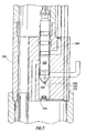
- FIG. 7 is a sectional view of a removable valve assembly 700 in a longitudinal bore 720 of a pump housing 705 with an electrical connection therebetween, in accordance with a further embodiment of the invention.
- the assembly 700 is illustrated only partially inserted into the housing 705.
- the housing 705 is electrically wired with conductors 710, 715 that lead to a lower portion of the longitudinal bore 720.
- a contact seat 725 is located within the bore 720 and is constructed and arranged to receive an electrode 730 protruding from the lower end of the valve assembly 700.
- the electrode 730 is seated in the contact seat 725 and an electrical connection between the housing 705 and the valve assembly 700 is made.
- valve assembly 700 may be actuated electrically through the use of a solenoid switch 735 disposed within the valve assembly 700.
- the housing includes flow paths formed therein that communicate with the valve assembly 700 and reduce the necessary bulk of the valve assembly 700.
Landscapes
- Engineering & Computer Science (AREA)
- Life Sciences & Earth Sciences (AREA)
- Geology (AREA)
- Mining & Mineral Resources (AREA)
- Physics & Mathematics (AREA)
- Environmental & Geological Engineering (AREA)
- Fluid Mechanics (AREA)
- General Life Sciences & Earth Sciences (AREA)
- Geochemistry & Mineralogy (AREA)
- Mechanical Engineering (AREA)
- General Engineering & Computer Science (AREA)
- Details Of Reciprocating Pumps (AREA)
Abstract
Description
- The present invention relates to a fluid operated pump for use in a wellbore.
- Oil and gas wells include a wellbore formed in the earth to access hydrocarbon-bearing formations. Typically, a borehole is initially formed and thereafter the borehole is lined with steel pipe, or casing in order to prevent cave in and facilitate the isolation of portions of the wellbore. To complete the well, at least one area of the wellbore casing is perforated to form a fluid path for the hydrocarbons to enter the wellbore. In some instances, natural formation pressure is adequate to bring production fluid to the surface for collection. More commonly however, some form of artificial lift is necessary to retrieve the fluid.
- Artificial lift methods are numerous and include various pumping arrangements. One common pump is a gas operated pump, as shown in Figure 1. Figure 1 is a section view of a wellbore with a gas operated pump disposed therein. The
pump 30 is located adjacent perforations in thewellbore 10. The pump operates with pressured gas injected from a highpressure gas vessel 24 into agas supply line 80 to avalve assembly 40 disposed in a body of thepump 30. Thevalve assembly 40 consists of aninjection control valve 70 for controlling the input of gas into anaccumulation chamber 34 and avent control valve 90 for controlling the venting of valve assemblies for a gas operated pump have an internal bypass passageway for injecting gas into the chamber. The internal bypass passageway must be a large enough diameter to facilitate a correct amount of gas flow into the chamber. These internal structures necessarily make the valve large and bulky. A bulky valve assembly is difficult to insert in a downhole pump because of space limitations in a wellbore and in a pump housing. - US Patent 2336683 Hatfield discloses a method and apparatus for pumping well fluid from a well utilising gas as the lifting medium. In one embodiment a valve assembly is insertable on the end of a macaroni through well tubing into a seating member, and the valve assembly is then actuable by a weight bar that is lowered through the macaroni on the end of a wireline. However, there is no suggestion that the valve assembly can be subsequently withdrawn from the well to enable it to be replaced.
- It is an object of the invention to provide a fluid operated pump having an improved valve assembly and operation.
- According to the present invention, there is provided a fluid operated pump for use in a wellbore, the pump comprising a housing with at least one longitudinal bore therethrough; a first fluid path formed in the housing and opening into the bore for communicating a pressurized fluid from the bore to an area below the housing; a second fluid path formed in the housing and opening into the bore for communicating an exhaust fluid from an area below the housing to the exterior of the housing; and a removable valve assembly axially insertable into the bore of the housing and having ports that are constructed and arranged in an outer valve surface to communicate with the first and second fluid paths when the valve assembly is inserted into the bore and to selectively direct the pressurized fluid and the exhaust fluid; characterised in that fluid actuating means is providing for communicating motive fluid to the bore in order to operate the valve assembly within the bore.
- The provision of such a removable valve assembly with actuating means for communicating motive fluid to the bore to operate the valve assembly within the bore enables particularly efficient operation of the valve assembly.
- The invention also provides a method of operating a fluid operated pump within a wellbore, the method utilizing a removable valve assembly within a longitudinal bore in a housing of the pump, wherein a first fluid path in the housing opening into the bore is provided for supply of pressurized fluid from the bore to an area of the pump below the housing, and a second fluid path in the housing opening into the bore is provided for an exhaust fluid from an area below the housing to the exterior of the housing, the method comprising lowering the valve assembly to a location in the wellbore proximate the bore in the housing; aligning the valve assembly with the bore; axially inserting the valve assembly into the bore such that ports in an outer valve surface communicate with the first and second fluid paths; and sealingly retaining the valve assembly in the bore during pumping of fluid by the pump; characterised in that the valve assembly is operated within the bore by motive fluid supplied to the bore by fluid actuating means.
- In order that the invention may be more fully understood, embodiments of the present invention will now be described, by way of example, with reference to the accompanying drawings, in which:
- Figure 1 is a sectional view of a prior art gas operated pump assembly in a well;
- Figure 2 is a sectional view of a housing for use in a first embodiment of the invention;
- Figure 3 illustrates a removable valve assembly disposed on a coiled tubing string for insertion into the housing of Figure 2;
- Figure 4 is a sectional view showing the removable valve assembly of Figure 3 disposed on coiled tubing and located in the bore of the housing of Figure 2;
- Figure 5 illustrates a removable valve assembly for a gas operated pump in accordance with an further embodiment of the invention;
- Figure 6 illustrates the valve assembly of Figure 5 inserted in a housing with an alignment tool being provided to install the valve assembly in the housing; and
- Figure 7 illustrates a removable valve assembly and a housing in a still further embodiment of the invention with an electrical connection means therebetween.
- Figure 2 is a sectional view through a
housing 200 of a gas operated pump in accordance with a preferred embodiment of the invention. Thehousing 200 includes twolongitudinal bores housing 200 includes an internally threadedportion 205 at its upper end for connection to a string of tubulars (not shown) and an externally threadedportion 210 at its lower end for connection to an accumulator chamber (not shown). Thehousing 200 has a firstlongitudinal bore 215 therethrough having an internally threadedportion 220 at its lower end for connection to a diptube (not shown). In use, thebore 215 serves as a conduit for production fluid pumped towards the surface of the well. Thehousing 200 also has a secondlongitudinal bore 225. Anaperture 235 formed in a wall of thehousing 200 provides communication between the secondlongitudinal bore 225 and the exterior of thehousing 200. Athird bore 230 provides communication between aninjection port 250 in the wall of the secondlongitudinal bore 225 and the lower end of thehousing 200 for injection of pressurized gas into the accumulation chamber (not shown). - The second
longitudinal bore 225 further includes afirst profile 240 and asecond profile 245 formed within thebore 225 to receive a removable valve assembly (not shown) that is insertable in theupper end 255 ofbore 225. In this arrangement, theprofiles - Figure 3 illustrates the
removable valve assembly 300 disposed on the end of a coiledtubing string 325 for insertion into thehousing 200 of Figure 2. Theremovable valve assembly 300 includes aninlet control valve 305, avent control valve 310, avalve stem 315 and anactuator 320. Thevalve stem 315 is connected to both theinlet control valve 305 and thevent control valve 310. Theactuator 320 moves thevalve stem 315, alternatively opening and closing theinlet control valve 305 and thevent control valve 310. When theinlet control valve 305 is in the open position, gas flows down the coiledtubing string 325 into theassembly 300 and out through agas outlet port 330. Alternatively, when thevent control valve 310 is in the open position, gas enters avent inlet port 340 and exits through avent outlet port 335. Afirst control conduit 345 and asecond control conduit 350 are housed inside the coiledtubing string 325. Thefirst control conduit 345 and thesecond control conduit 350 are typically hydraulic control lines and are used to actuate thevalve assembly 300. Additionally, electrical power can be transmitted through the one or more of thecontrol conduits valve assembly 300. Thevalve assembly 300 may include data transmitting means to transmit data, such as pressure and temperature within the pump chamber, through thecontrol conduits valve assembly 300 or thehousing 200 may include sensors. The transmitting means can include fiber optic cable. - A
first seal 355,second seal 360, andthird seal 365 are circumferentially mounted around an external surface of thevalve assembly 300. The purpose of the seals is to isolate fluid paths between thevalve assembly 300 and the housing 200 (Figure 2) when thevalve assembly 300 is inserted therein. Theassembly 300 further includes afirst key 370 and asecond key 375 to secure thevalve assembly 300 axially within thehousing 200. Thefirst key 370 and thesecond key 375 are outwardly biased and are designed to mate with the profiles in the interior surface of the housing 200 (Figure 2). - Figure 4 is a sectional view of the
valve assembly 300 disposed in thehousing 200. In the arrangement of Figure 4, thevalve assembly 300 is shown at the end of the coiledtubing string 325 that provides a source of pressurized gas to operate the pump. Theaccumulator chamber 415 for collecting formation fluid is secured to thehousing 200 by the externally threadedportion 210 at the lower end of thehousing 200. Thetubing string 405 is secured to thehousing 200 at the internally threadedportion 205. Adiptube 410 is secured to thehousing 200 by way of the internally threadedportion 220 of the firstlongitudinal bore 215. Avent line 420 is secured to thehousing 200 at theaperture 235 to provide a passageway for gas venting from theaccumulator chamber 415. - In operation, the
removable valve assembly 300 is installed at an end of the coiledtubing string 325 and thestring 325 is inserted intubing string 405 at the top of the wellbore and thevalve assembly 300 is lowered on thestring 325 towards thehousing 200. As thevalve assembly 300 reaches thehousing 200, a profile means and guide orient and align thevalve assembly 300 with the secondlongitudinal bore 225 which is offset from the center of thehousing 200. Profile means and guides are well known in the art and typically include some mechanical means for orienting a device in a wellbore. After insertion into theupper end 255 of thebore 225, thevalve assembly 300 is urged downwards until thefirst key 370 and thesecond key 375 of thevalve assembly 300 are secured in place in thefirst profile 240 and thesecond profile 245 of thehousing 200. Mating angles on the keys and profiles permit the retention of the valve in thehousing 200. Thefirst seal 355 and thesecond seal 360 form a barrier on the top and bottom of theinjection port 250 to prevent leakage of injected gas into theaccumulator chamber 415. Thesecond seal 360 and thethird seal 365 provide a barrier on the top and bottom of theaperture 235 to prevent leakage of gas exiting thevent line 420. - After such installation of the
valve assembly 300 the formation fluid supplied to theaccumulator chamber 415 is pumped by operation of theinlet control valve 305 and thevent control valve 310 by means of theactuator 320 in the manner already described. 7 - Figure 5 is a sectional view of an
alternative valve assembly 500 and Figure 6 is a sectional view of thevalve assembly 500 installed in ahousing 600 in accordance with a further embodiment of the invention. Thehousing 600 of Figure 6 includes additional fluid paths formed therein but is otherwise similar to thehousing 200 of Figure 2 and thevalve assembly 500 of Figure 6 includes additional fluid paths formed therein but is otherwise similar to thevalve assembly 300 of Figure 3, and like reference numerals are therefore used in Figure 6 to denote similar parts in these figures.Hydraulic conduits housing 600 and serve to carry hydraulic power fluid from an upper end of thehousing 600 to thelongitudinal bore 645 formed in thehousing 600. Theconduits bore 645 at locations ensuring that they will communicate with thevalve assembly 500 after it has been installed in thebore 645 and is retained therein with the retention means described with respect to Figure 4. Also formed in thehousing 600 is aninternal gas line 640 providing communication between the upper end of thehousing 600 and thebore 645. - By providing
hydraulic conduits gas line 640 internally within thehousing 600, there is no need for separate hydraulic lines or a gas supply line to remain attached at an upper end of thevalve assembly 500. As illustrated in Figure 6, thevalve assembly 500 is installed in thebore 645 with a selective connector orgripping tool 607 that temporarily retains thevalve assembly 500 by gripping afish neck 580 formed at the upper end of thevalve assembly 500. Gripping tools typically operate mechanically with inwardly movable fingers. A kickover tool can be utilized to align thevalve assembly 500 with the offsetbore 645. Kickover tools and gripping tools are well known in the art. Because no rigid conduits are needed between the surface of the well and the upper end of thevalve assembly 500, theassembly 500 can be inserted and removed from the housing using wireline or slick line. After completion of the pumping operation and when it is required to withdraw thevalve assembly 500 from the wellbore, thevalve assembly 500 can simply be retrieved from thebore 645 in thehousing 600 on the end of the wireline by exerting sufficient upward force on the wireline to overcome the sealing engagement of thevalve assembly 500 within thebore 645. - Figure 7 is a sectional view of a
removable valve assembly 700 in alongitudinal bore 720 of apump housing 705 with an electrical connection therebetween, in accordance with a further embodiment of the invention. For clarity, theassembly 700 is illustrated only partially inserted into thehousing 705. In the embodiment of Figure 7, thehousing 705 is electrically wired withconductors longitudinal bore 720. Acontact seat 725 is located within thebore 720 and is constructed and arranged to receive anelectrode 730 protruding from the lower end of thevalve assembly 700. As theassembly 700 is inserted into thebore 720 and is axially located therein, theelectrode 730 is seated in thecontact seat 725 and an electrical connection between thehousing 705 and thevalve assembly 700 is made. Thereafter, thevalve assembly 700 may be actuated electrically through the use of asolenoid switch 735 disposed within thevalve assembly 700. As in the other embodiment of the invention, the housing includes flow paths formed therein that communicate with thevalve assembly 700 and reduce the necessary bulk of thevalve assembly 700. After completion of the pumping operation and when it is required to withdraw thevalve assembly 700 from the wellbore, thevalve assembly 700 can simply be retrieved from thebore 720 in thehousing 705 on the end of the wireline.
Claims (18)
- A fluid operated pump for use in a wellbore, the pump comprising:a housing (200, 600, 705) with at least one longitudinal bore (225, 645, 720) therethrough;a first fluid path (250) formed in the housing (200, 600, 705) and opening into the bore (225, 645, 720) for communicating a pressurized fluid from the bore (225, 645, 720) to an area below the housing (200, 600, 705);a second fluid path (235) formed in the housing (200, 600, 705) and opening into the bore (225, 645, 720) for communicating an exhaust fluid from an area below the housing (200, 600, 705) to the exterior of the housing; anda removable valve assembly (300, 500, 700) axially insertable into the bore (225, 645, 720) of the housing (200, 600, 705) and having ports (330,335) that are constructed and arranged in an outer valve surface to communicate with the first and second fluid paths (250, 235) when the valve assembly (300, 500, 700) is inserted into the bore (225, 645, 720) and to selectively direct the pressurized fluid and the exhaust fluid;characterised in that fluid actuating means (345, 350, 630, 635) is providing for communicating motive fluid to the bore (225, 645, 720) in order to operate the valve assembly (300, 500, 700) within the bore (225, 645, 720).
- The pump of claim 1, wherein the area below the housing (200, 600, 705) comprises an accumulator chamber (415) for receiving production fluid to be pumped by the action of the pressurized fluid.
- The pump of claim 1 or 2, wherein the first fluid path (250) further includes a path extending from the bore (225, 645, 720) to an area above the housing (200, 600, 705) for communicating the pressurized fluid from the area above the housing (200, 600, 705) to the bore (225, 645, 720).
- The pump of any preceding claim, further including at least one seal member (360) between the valve assembly (300, 500, 700) and the bore (225, 645, 720) for isolating the first and second fluid paths (250, 235) from each other.
- The pump of any preceding claim, further including a retention assembly (240, 245, 370, 375) between the valve assembly (300, 500, 700) and the bore (225, 645, 720) for retaining the valve assembly (300, 500, 700) in a predetermined axial position within the bore (225, 645, 720).
- The pump of claim 5, wherein the retention assembly includes at least one outwardly biased formation (370, 375) extending radially from an outer surface of the valve assembly (300, 500, 700) and constructed and arranged to land in a profile (240, 245) formed on an inner surface of the bore (225, 645, 720), whereby, upon insertion in the bore (225, 645, 720), the valve assembly (300, 500, 700) seats in the bore (225, 645, 720) in the predetermined axial position.
- The pump of claim 5 or 6, wherein the first and second fluid paths (250, 235) are interruptably completed when the valve assembly (300, 500, 700) is in the predetermined axial position within the bore (225, 645, 720).
- The pump of any preceding claim, wherein the removable valve assembly (300) includes a coiled tubing string (325) extending from an upper end thereof, the string (325) serving as a conduit for the pressurized fluid.
- The pump of any preceding claim, wherein the pump further includes an electrical connection (725, 730) between the valve assembly (700) and the bore (720) for actuation of the shift the valve assembly (700).
- The pump of claim 9, wherein the electrical connection is made between a first mating member (730) on the valve assembly (700) and a second mating member (725) disposed in the bore (720), the mating members (725, 730) mating with one another as the valve assembly (700) is located in a predetermined axial position within the bore (720).
- The pump of any preceding claim, wherein the valve assembly (500, 700) is connected to a wireline by a selective connector (607) for insertion into the bore (645, 720), the valve assembly (500, 700) being subsequently releasable from the wireline by disconnection of the selective connector (607).
- The pump of claim 11, wherein the selective connector (607) is operable from the surface of the well.
- The pump of any preceding claim, further including an alignment member constructed and arranged to align the valve assembly (300, 500, 700) with the bore (225, 645, 720) prior to insertion of the valve assembly (300, 500, 700)) into the bore (225, 645, 720).
- A method of operating a fluid operated pump within a wellbore, the method utilizing a removable valve assembly (300, 500, 700) within a longitudinal bore (225, 645, 720) in a housing (200, 600, 705) of the pump, wherein a first fluid path (250) in the housing (200, 600, 705) opening into the bore (225, 645, 720) is provided for supply of pressurized fluid from the bore to an area of the pump below the housing, and a second fluid path (235) in the housing (200, 600, 705) opening into the bore (225, 645, 720) is provided for an exhaust fluid from an area below the housing to the exterior of the housing, the method comprising:lowering the valve assembly to a location in the wellbore proximate the bore (225, 645, 720) in the housing (200, 600, 705);aligning the valve assembly (300, 500, 700) with the bore (225, 645, 720);axially inserting the valve assembly (300, 500, 700) into the bore (225, 645, 720) such that ports in an outer valve surface communicate with the first and second fluid paths (250, 235) ; andsealingly retaining the valve assembly (300, 500, 700) in the bore (225, 645, 720) during pumping of fluid by the pump;characterised in that the valve assembly (300, 500, 700) is operated within the bore (225, 645, 720) by motive fluid supplied to the bore (225, 645, 720) by fluid actuating means (345, 350, 630, 635).
- The method of claim 14, wherein the pumping of fluid by the pump is effected by movement of the valve assembly (300, 500, 700) by motive fluid supplied to the bore (225, 645, 720).
- The method of claim 15, wherein the motive fluid is a hydraulic fluid supplied by hydraulic control conduit means (345, 350, 630, 635).
- The method of claim 14, 15 or 16, further including making an electrical connection (725, 730) between the valve assembly (700) and the bore (720).
- The method of any one of claims 14 to 17, wherein the pumping of fluid by the pump is effected by the accumulation of production fluid to be pumped in an accumulator chamber (415) and the supply of pressurized fluid to the accumulator chamber (415) to force the production fluid along the wellbore.
Applications Claiming Priority (2)
| Application Number | Priority Date | Filing Date | Title |
|---|---|---|---|
| US23940300P | 2000-10-11 | 2000-10-11 | |
| EP01974496A EP1325207B1 (en) | 2000-10-11 | 2001-10-11 | Gas operated pump for use in a wellbore |
Related Parent Applications (1)
| Application Number | Title | Priority Date | Filing Date |
|---|---|---|---|
| EP01974496A Division EP1325207B1 (en) | 2000-10-11 | 2001-10-11 | Gas operated pump for use in a wellbore |
Publications (2)
| Publication Number | Publication Date |
|---|---|
| EP1666697A1 true EP1666697A1 (en) | 2006-06-07 |
| EP1666697B1 EP1666697B1 (en) | 2008-07-02 |
Family
ID=36242283
Family Applications (1)
| Application Number | Title | Priority Date | Filing Date |
|---|---|---|---|
| EP06110792A Expired - Lifetime EP1666697B1 (en) | 2000-10-11 | 2001-10-11 | Fluid operated pump for use in a wellbore |
Country Status (1)
| Country | Link |
|---|---|
| EP (1) | EP1666697B1 (en) |
Citations (6)
| Publication number | Priority date | Publication date | Assignee | Title |
|---|---|---|---|---|
| US2336683A (en) * | 1940-06-25 | 1943-12-14 | Nat Supply Co | Gas lift pump |
| US3833060A (en) * | 1973-07-11 | 1974-09-03 | Union Oil Co | Well completion and pumping system |
| US3873238A (en) * | 1973-09-19 | 1975-03-25 | Johnnie A Elfarr | Method and apparatus for flowing crude oil from a well |
| US5325917A (en) * | 1991-10-21 | 1994-07-05 | Halliburton Company | Short stroke casing valve with positioning and jetting tools therefor |
| US5806598A (en) * | 1996-08-06 | 1998-09-15 | Amani; Mohammad | Apparatus and method for removing fluids from underground wells |
| US6068015A (en) * | 1996-08-15 | 2000-05-30 | Camco International Inc. | Sidepocket mandrel with orienting feature |
-
2001
- 2001-10-11 EP EP06110792A patent/EP1666697B1/en not_active Expired - Lifetime
Patent Citations (6)
| Publication number | Priority date | Publication date | Assignee | Title |
|---|---|---|---|---|
| US2336683A (en) * | 1940-06-25 | 1943-12-14 | Nat Supply Co | Gas lift pump |
| US3833060A (en) * | 1973-07-11 | 1974-09-03 | Union Oil Co | Well completion and pumping system |
| US3873238A (en) * | 1973-09-19 | 1975-03-25 | Johnnie A Elfarr | Method and apparatus for flowing crude oil from a well |
| US5325917A (en) * | 1991-10-21 | 1994-07-05 | Halliburton Company | Short stroke casing valve with positioning and jetting tools therefor |
| US5806598A (en) * | 1996-08-06 | 1998-09-15 | Amani; Mohammad | Apparatus and method for removing fluids from underground wells |
| US6068015A (en) * | 1996-08-15 | 2000-05-30 | Camco International Inc. | Sidepocket mandrel with orienting feature |
Also Published As
| Publication number | Publication date |
|---|---|
| EP1666697B1 (en) | 2008-07-02 |
Similar Documents
| Publication | Publication Date | Title |
|---|---|---|
| EP1325207B1 (en) | Gas operated pump for use in a wellbore | |
| RU2401936C1 (en) | Procedure and device for intrawell selective communication by means of fluid medium | |
| US6286594B1 (en) | Downhole valve | |
| US4425965A (en) | Safety system for submersible pump | |
| US8839850B2 (en) | Active integrated completion installation system and method | |
| RU2307920C1 (en) | Device and method for underground well completion | |
| EP2630326B1 (en) | Fluid injection device | |
| AU777219B2 (en) | Downhole well-control valve reservoir monitoring and drawdown optimization system | |
| US7823633B2 (en) | Valve apparatus | |
| US6508309B1 (en) | Valve assembly | |
| USRE40308E1 (en) | Multi-purpose injection and production well system | |
| US4350205A (en) | Work over methods and apparatus | |
| NO333804B1 (en) | Sand control method and apparatus | |
| EP2103776B1 (en) | System and method for selectively operating a hydraulic nipple | |
| GB2235228A (en) | Geothermal well chemical injection system | |
| EP1033470B1 (en) | Downhole hydraulic path selection | |
| WO1990000667A1 (en) | Plug for well logging operations | |
| AU2018293286B2 (en) | Valve system | |
| CA2641707C (en) | Valve apparatus | |
| EP2351906A2 (en) | Retrofit wellbore fluid injection system | |
| US11702913B2 (en) | Wellbore system having an annulus safety valve | |
| CA1209464A (en) | Well pumping apparatus and method | |
| EP1666697B1 (en) | Fluid operated pump for use in a wellbore | |
| US12590516B2 (en) | Contingency sealing option for surface controlled flow control device | |
| CA3065191C (en) | Valve system |
Legal Events
| Date | Code | Title | Description |
|---|---|---|---|
| PUAI | Public reference made under article 153(3) epc to a published international application that has entered the european phase |
Free format text: ORIGINAL CODE: 0009012 |
|
| 17P | Request for examination filed |
Effective date: 20060310 |
|
| AC | Divisional application: reference to earlier application |
Ref document number: 1325207 Country of ref document: EP Kind code of ref document: P |
|
| AK | Designated contracting states |
Kind code of ref document: A1 Designated state(s): AT BE BG CH CY CZ DE DK EE ES FI FR GB GR HU IE IS IT LI LT LU LV MC NL PL PT RO SE SI SK TR |
|
| AX | Request for extension of the european patent |
Extension state: AL BA HR MK YU |
|
| 17Q | First examination report despatched |
Effective date: 20060901 |
|
| 17Q | First examination report despatched |
Effective date: 20060901 |
|
| AKX | Designation fees paid |
Designated state(s): GB |
|
| REG | Reference to a national code |
Ref country code: DE Ref legal event code: 8566 |
|
| 17Q | First examination report despatched |
Effective date: 20060901 |
|
| GRAP | Despatch of communication of intention to grant a patent |
Free format text: ORIGINAL CODE: EPIDOSNIGR1 |
|
| GRAS | Grant fee paid |
Free format text: ORIGINAL CODE: EPIDOSNIGR3 |
|
| GRAA | (expected) grant |
Free format text: ORIGINAL CODE: 0009210 |
|
| AC | Divisional application: reference to earlier application |
Ref document number: 1325207 Country of ref document: EP Kind code of ref document: P |
|
| AK | Designated contracting states |
Kind code of ref document: B1 Designated state(s): GB |
|
| REG | Reference to a national code |
Ref country code: GB Ref legal event code: FG4D |
|
| PLBE | No opposition filed within time limit |
Free format text: ORIGINAL CODE: 0009261 |
|
| STAA | Information on the status of an ep patent application or granted ep patent |
Free format text: STATUS: NO OPPOSITION FILED WITHIN TIME LIMIT |
|
| 26N | No opposition filed |
Effective date: 20090403 |
|
| REG | Reference to a national code |
Ref country code: GB Ref legal event code: 732E Free format text: REGISTERED BETWEEN 20151022 AND 20151028 |
|
| PGFP | Annual fee paid to national office [announced via postgrant information from national office to epo] |
Ref country code: GB Payment date: 20151007 Year of fee payment: 15 |
|
| GBPC | Gb: european patent ceased through non-payment of renewal fee |
Effective date: 20161011 |
|
| PG25 | Lapsed in a contracting state [announced via postgrant information from national office to epo] |
Ref country code: GB Free format text: LAPSE BECAUSE OF NON-PAYMENT OF DUE FEES Effective date: 20161011 |