EP1666429A1 - Optical fiber processing system and method - Google Patents
Optical fiber processing system and method Download PDFInfo
- Publication number
- EP1666429A1 EP1666429A1 EP04747135A EP04747135A EP1666429A1 EP 1666429 A1 EP1666429 A1 EP 1666429A1 EP 04747135 A EP04747135 A EP 04747135A EP 04747135 A EP04747135 A EP 04747135A EP 1666429 A1 EP1666429 A1 EP 1666429A1
- Authority
- EP
- European Patent Office
- Prior art keywords
- optical fiber
- treatment
- processing apparatus
- fiber processing
- bobbins
- Prior art date
- Legal status (The legal status is an assumption and is not a legal conclusion. Google has not performed a legal analysis and makes no representation as to the accuracy of the status listed.)
- Withdrawn
Links
- 239000013307 optical fiber Substances 0.000 title claims abstract description 87
- 238000000034 method Methods 0.000 title claims abstract description 32
- 238000011282 treatment Methods 0.000 claims abstract description 122
- 239000007789 gas Substances 0.000 claims abstract description 34
- UFHFLCQGNIYNRP-VVKOMZTBSA-N Dideuterium Chemical compound [2H][2H] UFHFLCQGNIYNRP-VVKOMZTBSA-N 0.000 claims abstract description 26
- 239000000835 fiber Substances 0.000 claims abstract description 8
- 230000008878 coupling Effects 0.000 claims description 3
- 238000010168 coupling process Methods 0.000 claims description 3
- 238000005859 coupling reaction Methods 0.000 claims description 3
- 239000011261 inert gas Substances 0.000 abstract description 4
- 230000000452 restraining effect Effects 0.000 abstract description 2
- 238000004904 shortening Methods 0.000 abstract description 2
- 239000001257 hydrogen Substances 0.000 description 6
- 229910052739 hydrogen Inorganic materials 0.000 description 6
- 238000010586 diagram Methods 0.000 description 5
- IJGRMHOSHXDMSA-UHFFFAOYSA-N Atomic nitrogen Chemical compound N#N IJGRMHOSHXDMSA-UHFFFAOYSA-N 0.000 description 4
- UFHFLCQGNIYNRP-UHFFFAOYSA-N Hydrogen Chemical compound [H][H] UFHFLCQGNIYNRP-UHFFFAOYSA-N 0.000 description 4
- 230000000694 effects Effects 0.000 description 4
- 230000005540 biological transmission Effects 0.000 description 3
- 238000010521 absorption reaction Methods 0.000 description 2
- 230000007423 decrease Effects 0.000 description 2
- 239000006185 dispersion Substances 0.000 description 2
- 150000002431 hydrogen Chemical class 0.000 description 2
- 125000002887 hydroxy group Chemical group [H]O* 0.000 description 2
- 239000000463 material Substances 0.000 description 2
- 229910052757 nitrogen Inorganic materials 0.000 description 2
- 230000004308 accommodation Effects 0.000 description 1
- 230000032683 aging Effects 0.000 description 1
- 230000007547 defect Effects 0.000 description 1
- 238000006073 displacement reaction Methods 0.000 description 1
- 239000011521 glass Substances 0.000 description 1
- 239000002184 metal Substances 0.000 description 1
- 238000012986 modification Methods 0.000 description 1
- 230000004048 modification Effects 0.000 description 1
- 230000003287 optical effect Effects 0.000 description 1
- 230000008054 signal transmission Effects 0.000 description 1
- 229910001220 stainless steel Inorganic materials 0.000 description 1
- 239000010935 stainless steel Substances 0.000 description 1
- 238000006467 substitution reaction Methods 0.000 description 1
Images


Classifications
-
- G—PHYSICS
- G02—OPTICS
- G02B—OPTICAL ELEMENTS, SYSTEMS OR APPARATUS
- G02B6/00—Light guides; Structural details of arrangements comprising light guides and other optical elements, e.g. couplings
-
- C—CHEMISTRY; METALLURGY
- C03—GLASS; MINERAL OR SLAG WOOL
- C03C—CHEMICAL COMPOSITION OF GLASSES, GLAZES OR VITREOUS ENAMELS; SURFACE TREATMENT OF GLASS; SURFACE TREATMENT OF FIBRES OR FILAMENTS MADE FROM GLASS, MINERALS OR SLAGS; JOINING GLASS TO GLASS OR OTHER MATERIALS
- C03C25/00—Surface treatment of fibres or filaments made from glass, minerals or slags
- C03C25/60—Surface treatment of fibres or filaments made from glass, minerals or slags by diffusing ions or metals into the surface
- C03C25/607—Surface treatment of fibres or filaments made from glass, minerals or slags by diffusing ions or metals into the surface in the gaseous phase
-
- C—CHEMISTRY; METALLURGY
- C03—GLASS; MINERAL OR SLAG WOOL
- C03C—CHEMICAL COMPOSITION OF GLASSES, GLAZES OR VITREOUS ENAMELS; SURFACE TREATMENT OF GLASS; SURFACE TREATMENT OF FIBRES OR FILAMENTS MADE FROM GLASS, MINERALS OR SLAGS; JOINING GLASS TO GLASS OR OTHER MATERIALS
- C03C13/00—Fibre or filament compositions
-
- C—CHEMISTRY; METALLURGY
- C03—GLASS; MINERAL OR SLAG WOOL
- C03C—CHEMICAL COMPOSITION OF GLASSES, GLAZES OR VITREOUS ENAMELS; SURFACE TREATMENT OF GLASS; SURFACE TREATMENT OF FIBRES OR FILAMENTS MADE FROM GLASS, MINERALS OR SLAGS; JOINING GLASS TO GLASS OR OTHER MATERIALS
- C03C13/00—Fibre or filament compositions
- C03C13/04—Fibre optics, e.g. core and clad fibre compositions
-
- C—CHEMISTRY; METALLURGY
- C03—GLASS; MINERAL OR SLAG WOOL
- C03C—CHEMICAL COMPOSITION OF GLASSES, GLAZES OR VITREOUS ENAMELS; SURFACE TREATMENT OF GLASS; SURFACE TREATMENT OF FIBRES OR FILAMENTS MADE FROM GLASS, MINERALS OR SLAGS; JOINING GLASS TO GLASS OR OTHER MATERIALS
- C03C13/00—Fibre or filament compositions
- C03C13/04—Fibre optics, e.g. core and clad fibre compositions
- C03C13/045—Silica-containing oxide glass compositions
- C03C13/047—Silica-containing oxide glass compositions containing deuterium
-
- C—CHEMISTRY; METALLURGY
- C03—GLASS; MINERAL OR SLAG WOOL
- C03C—CHEMICAL COMPOSITION OF GLASSES, GLAZES OR VITREOUS ENAMELS; SURFACE TREATMENT OF GLASS; SURFACE TREATMENT OF FIBRES OR FILAMENTS MADE FROM GLASS, MINERALS OR SLAGS; JOINING GLASS TO GLASS OR OTHER MATERIALS
- C03C25/00—Surface treatment of fibres or filaments made from glass, minerals or slags
- C03C25/60—Surface treatment of fibres or filaments made from glass, minerals or slags by diffusing ions or metals into the surface
-
- C—CHEMISTRY; METALLURGY
- C03—GLASS; MINERAL OR SLAG WOOL
- C03B—MANUFACTURE, SHAPING, OR SUPPLEMENTARY PROCESSES
- C03B2201/00—Type of glass produced
- C03B2201/06—Doped silica-based glasses
- C03B2201/20—Doped silica-based glasses doped with non-metals other than boron or fluorine
- C03B2201/22—Doped silica-based glasses doped with non-metals other than boron or fluorine doped with deuterium
Definitions
- the present invention relates to a gas treatment of an optical fiber, and particularly relates to a gas treatment performed to improve a hydrogen-resistant characteristic of an optical fiber. More particularly, the present invention relates to an optical fiber processing apparatus and a process method performed by a gas including a heavy hydrogen.
- An optical fiber most used in optical transmission line is a single mode optical fiber having a zero dispersion wavelength near 1310 nm. Conventionally, this optical fiber has been used for the transmission of a signal light of 1310 nm. However, these days the optical fiber is used to transmit a signal light having other wavelengths due to the advance of a dispersion compensation technique.
- CWDM Coarse Wavelength Division, Multiplexing
- the transmission technique restrains the generation of crosstalk between each signal wavelength by broadening a wavelength interval to about 25 nm even if a cheap light source is used.
- a usable wavelength region is wide.
- an absorption loss peak hereinafter, referred to as an OH peak
- This wavelength region cannot be utilized.
- a low-moisture optical fiber is developed, and is prescribed as an International Standard in ITU-T G652 table C.
- Such an optical fiber initially requires a small OH peak and also requires a small OH peak after aging by hydrogen.
- a method for processing an optical fiber in heavy hydrogen as one method improving a hydrogen-resistant characteristic of an optical fiber.
- This method is a method having a characteristic that heavy hydrogen D reacts to a defect in an optical fiber in the same way as that of hydrogen H and yet an OD group does not cause an absorption loss peak in a wavelength area used as signal light because the OD group is different from an OH group. See, for example, Patent Documents 1, 2, and 3.
- a process of an optical fiber by heavy hydrogen as described above is performed for predetermined time in a state where an optical fiber is put in a container that can be sealed and the container is filled with heavy hydrogen to form an atmosphere containing heavy hydrogen. Since the heavy hydrogen is combustible gas similarly to hydrogen, the atmosphere in the container should be displaced with inert gas or the like such as nitrogen safely enough before filling with an atmosphere containing heavy hydrogen.
- a treatment container has been grown in size to process a large quantity of optical fiber.
- a conventional apparatus is shown in Fig. 5. This apparatus can process a large quantity of optical fiber at a time by arranging multiple bobbins, on which fiber to be processed is wound, on a plurality of shelves.
- a small quantity of optical fiber is processed, there has been a problem that it requires the same amount of heavy hydrogen and time as an amount and time when a large quantity of optical fiber is processed.
- an object of the present invention is to provide an optical fiber processing apparatus and a process method capable of shortening time required for replacing an atmosphere in a treatment container with inert gas and filling with heavy hydrogen and of restraining an amount used of expensive heavy hydrogen.
- the optical fiber processing apparatus of the present invention includes a plurality of containers for processing optical fiber that are spatially coupled by piping, each treatment container including a treatment chamber that can be sealed and accommodate one or more bobbins on which fiber to be processed is wound, in which the treatment chamber is supplied with treatment gas, and the optical fiber is processed by the gas.
- the treatment gas may be heavy hydrogen or gas including heavy hydrogen.
- the treatment container may arrange and accommodate the plurality of bobbins on a line in the axial direction in which the optical fiber is wound. Further, in the optical fiber processing apparatus, a cross section perpendicular to the direction in which the bobbins are arranged may have the substantially same magnitude as that of a cross section perpendicular to the direction in the bobbins, in the treatment chamber of the treatment container.
- the treatment container may have a transparent window through which whether the bobbins are accommodated in the treatment chamber can be comprehended from the outside. Further, in the optical fiber processing apparatus, the window may lengthwise be arranged in the direction in which the bobbins in the treatment container are arranged.
- the optical fiber processing apparatus may further include a detecting section that detects whether the bobbins are accommodated in the treatment chamber of the treatment container. Further, in the optical fiber processing apparatus, the detecting section may include a mass meter that measures mass of the treatment container.
- the treatment container according to the present invention may have a tubelike door of which one end can be opened or closed, a cross sectional shape of the treatment container may have a circle or a shape similar to the circle, and the treatment chamber of the treatment container may include a slidable tray therein.
- the treatment containers may be connected to one another by piping to be exhausted by a vacuum pump, the optical fiber processing apparatus may further include valves that are provided in the piping for coupling the plurality of treatment containers, in which some of the plurality of treatment containers are freely disconnected from or connected to other treatment containers and an air supply and exhaust system by the valves, and the optical fiber processing apparatus may further include a system that controls and manages a gas process for the optical fiber in each treatment container in an integrated fashion.
- a method for processing optical fiber according to the present invention uses the optical fiber processing apparatus.
- an optical fiber processing apparatus and a process method of the present invention it is possible to process a plurality of treatment containers under a gas atmosphere individually or in combination with one another using some containers, in concert with the number of bobbins on which fiber be processed is wound. Since time required for processing gas decreases and an amount used of heavy hydrogen decreases, a process cost is significantly reduced. Furthermore, it is possible to control and manage a gas process for optical fiber in each treatment container and thus reduce the required workforce.
- Fig. 1 is an explanation diagram exemplary showing an optical fiber processing apparatus of the present invention in which a plurality of treatment containers is spatially coupled by piping.
- Fig. 2 is a perspective view exemplary showing a bobbin on which fiber to be processed is wound.
- Fig. 3 is a schematic perspective diagram showing a state that a tray carrying a plurality of bobbins is taken out and put in a treatment container.
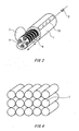
- Fig. 4 is a schematic perspective diagram showing an arrangement example of 15 treatment containers according to the present invention.
- Fig. 5 is a schematic perspective diagram showing a conventional optical fiber processing apparatus.
- the present invention can have a treatment container configuration suited to an amount of fiber to be processed using treatment containers individually or in combination with one another, by spatially coupling the plurality of independent treatment containers, which can respectively accommodate a few bobbins, by means of piping and disconnecting and connecting the containers from/to one another using the arrangement of valves.
- a treatment container configuration suited to an amount of fiber to be processed using treatment containers individually or in combination with one another, by spatially coupling the plurality of independent treatment containers, which can respectively accommodate a few bobbins, by means of piping and disconnecting and connecting the containers from/to one another using the arrangement of valves.
- Fig. 1 shows an optical fiber processing apparatus according to an embodiment of the present invention.
- the processing apparatus includes a plurality of tubular treatment containers 1 that is spatially coupled with one another by means of piping.
- Each treatment container 1 is piped so as to be able to control and manage an atmosphere individually and in an integrated fashion, and valves 2 for controlling an atmosphere in the treatment containers are provided on a path of piping.
- a vacuum pump for exhaust 3 is connected to the piping in order to efficiently perform displacement of heavy hydrogen D 2 source and nitrogen N 2 source, and further exhaust gas in the treatment containers via an air source and a flow controller (MFC).
- MFC flow controller
- Fig. 2 shows a bobbin 4 accommodated in the accommodation container 1.
- Optical fiber 5 is wound on the bobbin 4 as shown in Fig. 2.
- An outside diameter on a cross section perpendicular to an axial direction, in which the optical fiber 5 is wound, in the bobbin 4 is 340 mm.
- Fig. 3 shows the treatment container 1.
- the treatment container 1 has a treatment chamber that is made of metal such as stainless steel and is hollow and tubelike. Furthermore, the treatment container 1 has a door 7 for opening or closing the treatment chamber and a tray 6 for holding a plurality of bobbins 4.
- the bobbins 4 are accommodated in the treatment chamber of the treatment container 1 in a state that the bobbins are put in the tray 6, as shown in Fig. 3, and are taken out and put in the container by opening and closing of the door 7 in the style of sliding.
- the treatment container 1 arranges in line and accommodates the plurality of bobbins 4 in an axial direction in which the optical fiber 5 is wound.
- the treatment container has the magnitude capable of arranging in line and accommodating, e.g., ten bobbins 4 at a maximum.
- the shape of treatment container 1 has a circular cross section or a polygonal cross section similar to a circle, and thus enables exhaust by a vacuum pump with a relatively small quantity of material and thin wall material, and further minimization of unnecessary space around bobbin 4 as much as possible.
- the cross section perpendicular to the direction in which the bobbins 4 in the treatment chamber of the treatment container 1 are arranged is the substantially same magnitude as that of the cross section perpendicular to that direction in the bobbins 4. For example, when an outside diameter of the bobbin 4 is 340 mm, an inside diameter of a cross section of a treatment chamber is 400 mm.
- the treatment container 1 may have a transparent window 10 through which it can be watched from the outside whether the bobbins 4 are accommodated in the treatment chamber.
- the window 10 uses, e.g., a glass plate.
- the window 10 may further be provided in the direction in which the bobbins 4 in the treatment container 1 are arranged lengthwise.
- a point at which the window 10 is provided is not limited to this, it may be provide in the door 7. In this way, it is possible to know whether the bobbins 4 are accommodated in the treatment chamber of the treatment container 1 without opening or closing the door 7 in the treatment container 1. Therefore, it is possible to prevent the treatment container 1 in which the bobbins 4 are not accommodated from being unnecessarily exhausted or supplied with treatment gas.
- the door 7, the valve 2, the flow controller (MFC), and the vacuum pump for exhaust 3 in the treatment container 1. are controlled and managed in an integrated fashion by means of a control unit not shown, in order to perform a gas treatment. In this manner, since a state of each treatment container is controlled and managed in an integrated fashion, there are performed, without fail, elapsed time for treatment in each treatment container, an atmosphere in the treatment container, opening and closing of the treatment container, disconnecting and connecting of each treatment container from/to a gas supply and exhaust system, and so on.
- Fig. 4 is a schematic perspective diagram showing an arrangement example of 15 treatment containers 1.
- These 15 treatment containers 1 can have a treatment container configuration according to an amount of fiber to be processed, by using these treatment containers individually or using some containers in combination with one another.
- the optical fiber processing apparatus may include a mass meter for measuring mass of the treatment container 1 in place of the window 10 or in addition to the window 10 shown in Fig. 3.
- This mass meter is an example of a detecting section in the present invention.
- the optical fiber processing apparatus may display that effect on a display or the like.
- the optical fiber processing apparatus may prohibit the operation of valve 2 of the treatment container 1 for which that effect has been detected. In this way, it is possible to know whether the bobbins are accommodated in the treatment chamber of the treatment container 1 without opening or closing the door 7 of the treatment container 1. Therefore, it is possible to prevent the treatment container 1 in which the bobbins 4 are not accommodated from being unnecessarily exhausted or being supplied with treatment gas.
- the treatment of optical fiber requires three and half days. However, since the optical fiber is drawn and accumulated for this period, it is preferable that the heavy hydrogen treatment of the optical fiber is performed in parallel with the drawing.
- some treatment containers are filled with an atmosphere containing heavy hydrogen and is under a processed state, and other treatment containers takes out and puts in the optical fiber, exhausts treatment gas, and introduces gas. In this way, gas treatments in various process steps are performed in parallel.
- An optical fiber processing apparatus and a process method of the present invention can apply optical fiber to various gas treatments in a state that the optical fiber is wound on a bobbin, in addition to a gas treatment performed to improve a hydrogen-resistant characteristic of the optical fiber.
Landscapes
- Chemical & Material Sciences (AREA)
- Life Sciences & Earth Sciences (AREA)
- Organic Chemistry (AREA)
- Engineering & Computer Science (AREA)
- Chemical Kinetics & Catalysis (AREA)
- General Chemical & Material Sciences (AREA)
- Geochemistry & Mineralogy (AREA)
- Materials Engineering (AREA)
- Physics & Mathematics (AREA)
- Optics & Photonics (AREA)
- General Life Sciences & Earth Sciences (AREA)
- General Physics & Mathematics (AREA)
- Optical Fibers, Optical Fiber Cores, And Optical Fiber Bundles (AREA)
- Surface Treatment Of Glass Fibres Or Filaments (AREA)
- Treatment Of Fiber Materials (AREA)
- Filling Or Discharging Of Gas Storage Vessels (AREA)
Abstract
There is provide an optical fiber processing apparatus and a process method capable of shortening time required for replacing an atmosphere in a treatment container with inert gas and filling with heavy hydrogen and of restraining an amount used of expensive heavy hydrogen. An optical fiber processing apparatus includes a plurality of containers 1 for processing optical fiber that are spatially coupled by piping, each treatment container 1 including a treatment chamber that can be sealed and accommodate one or more bobbins 4 on which fiber to be processed is wound, in which the treatment chamber is supplied with treatment gas, and the optical fiber is processed by the gas. The treatment gas is heavy hydrogen or gas including the heavy hydrogen.
Description
- The present application also relates to the following application, the contents of which are incorporated herein by reference if applicable.
A Japanese Patent Application No. 2003-271859
Filed on: July 8, 2003. - The present invention relates to a gas treatment of an optical fiber, and particularly relates to a gas treatment performed to improve a hydrogen-resistant characteristic of an optical fiber. More particularly, the present invention relates to an optical fiber processing apparatus and a process method performed by a gas including a heavy hydrogen.
- An optical fiber most used in optical transmission line is a single mode optical fiber having a zero dispersion wavelength near 1310 nm. Conventionally, this optical fiber has been used for the transmission of a signal light of 1310 nm. However, these days the optical fiber is used to transmit a signal light having other wavelengths due to the advance of a dispersion compensation technique.
- In recent years, there has been developed a CWDM (Coarse Wavelength Division, Multiplexing) technique in order to comply with the increase of a transmission capacity to be requested at low cost. The transmission technique restrains the generation of crosstalk between each signal wavelength by broadening a wavelength interval to about 25 nm even if a cheap light source is used. In order to transmit much signal light using an optical fiber in the technique, it is desirable that a usable wavelength region is wide. However, in a conventional single mode optical fiber, there is an absorption loss peak (hereinafter, referred to as an OH peak) caused by an OH group in an optical fiber near 1383 nm. This wavelength region cannot be utilized. In order to use this region, a low-moisture optical fiber is developed, and is prescribed as an International Standard in ITU-T G652 table C.
- Such an optical fiber initially requires a small OH peak and also requires a small OH peak after aging by hydrogen. For this reason, there is a method for processing an optical fiber in heavy hydrogen as one method improving a hydrogen-resistant characteristic of an optical fiber. This method is a method having a characteristic that heavy hydrogen D reacts to a defect in an optical fiber in the same way as that of hydrogen H and yet an OD group does not cause an absorption loss peak in a wavelength area used as signal light because the OD group is different from an OH group. See, for example,
Patent Documents 1, 2, and 3. - [Patent Document 1] Japanese Patent Application publication No. 60-90852
- [Patent Document 2] Japanese Patent Application Publication No. 7-277770
- [Patent Document 3] Japanese Patent Application Publication No. 2000-148450
- A process of an optical fiber by heavy hydrogen as described above is performed for predetermined time in a state where an optical fiber is put in a container that can be sealed and the container is filled with heavy hydrogen to form an atmosphere containing heavy hydrogen. Since the heavy hydrogen is combustible gas similarly to hydrogen, the atmosphere in the container should be displaced with inert gas or the like such as nitrogen safely enough before filling with an atmosphere containing heavy hydrogen.
- Conventionally, a treatment container has been grown in size to process a large quantity of optical fiber. However, when a container grows in size, it takes time to displace components in the container with inert gas and fill with an atmosphere containing heavy hydrogen. A conventional apparatus is shown in Fig. 5. This apparatus can process a large quantity of optical fiber at a time by arranging multiple bobbins, on which fiber to be processed is wound, on a plurality of shelves. However, although a small quantity of optical fiber is processed, there has been a problem that it requires the same amount of heavy hydrogen and time as an amount and time when a large quantity of optical fiber is processed.
- In consideration of the problem, an object of the present invention is to provide an optical fiber processing apparatus and a process method capable of shortening time required for replacing an atmosphere in a treatment container with inert gas and filling with heavy hydrogen and of restraining an amount used of expensive heavy hydrogen.
- The optical fiber processing apparatus of the present invention includes a plurality of containers for processing optical fiber that are spatially coupled by piping, each treatment container including a treatment chamber that can be sealed and accommodate one or more bobbins on which fiber to be processed is wound, in which the treatment chamber is supplied with treatment gas, and the optical fiber is processed by the gas. The treatment gas may be heavy hydrogen or gas including heavy hydrogen.
- In the optical fiber processing apparatus, the treatment container may arrange and accommodate the plurality of bobbins on a line in the axial direction in which the optical fiber is wound. Further, in the optical fiber processing apparatus, a cross section perpendicular to the direction in which the bobbins are arranged may have the substantially same magnitude as that of a cross section perpendicular to the direction in the bobbins, in the treatment chamber of the treatment container.
- In the optical fiber processing apparatus, the treatment container may have a transparent window through which whether the bobbins are accommodated in the treatment chamber can be comprehended from the outside. Further, in the optical fiber processing apparatus, the window may lengthwise be arranged in the direction in which the bobbins in the treatment container are arranged.
- The optical fiber processing apparatus may further include a detecting section that detects whether the bobbins are accommodated in the treatment chamber of the treatment container. Further, in the optical fiber processing apparatus, the detecting section may include a mass meter that measures mass of the treatment container.
- The treatment container according to the present invention may have a tubelike door of which one end can be opened or closed, a cross sectional shape of the treatment container may have a circle or a shape similar to the circle, and the treatment chamber of the treatment container may include a slidable tray therein. The treatment containers may be connected to one another by piping to be exhausted by a vacuum pump, the optical fiber processing apparatus may further include valves that are provided in the piping for coupling the plurality of treatment containers, in which some of the plurality of treatment containers are freely disconnected from or connected to other treatment containers and an air supply and exhaust system by the valves, and the optical fiber processing apparatus may further include a system that controls and manages a gas process for the optical fiber in each treatment container in an integrated fashion.
In addition, a method for processing optical fiber according to the present invention uses the optical fiber processing apparatus. - The summary of the invention does not necessarily describe all necessary features of the present invention. The present invention may also be a sub-combination of the features described above.
- According to an optical fiber processing apparatus and a process method of the present invention, it is possible to process a plurality of treatment containers under a gas atmosphere individually or in combination with one another using some containers, in concert with the number of bobbins on which fiber be processed is wound. Since time required for processing gas decreases and an amount used of heavy hydrogen decreases, a process cost is significantly reduced. Furthermore, it is possible to control and manage a gas process for optical fiber in each treatment container and thus reduce the required workforce.
- Fig. 1 is an explanation diagram exemplary showing an optical fiber processing apparatus of the present invention in which a plurality of treatment containers is spatially coupled by piping.
- Fig. 2 is a perspective view exemplary showing a bobbin on which fiber to be processed is wound.
- Fig. 3 is a schematic perspective diagram showing a state that a tray carrying a plurality of bobbins is taken out and put in a treatment container.
- Fig. 4 is a schematic perspective diagram showing an arrangement example of 15 treatment containers according to the present invention.
- Fig. 5 is a schematic perspective diagram showing a conventional optical fiber processing apparatus.
- The invention will now be described based on the preferred embodiments, which do not intend to limit the scope of the present invention, but exemplify the invention. All of the features and the combinations thereof described in the embodiment are not necessarily essential to the invention.
- As a result of a repeated keen examination, the present invention can have a treatment container configuration suited to an amount of fiber to be processed using treatment containers individually or in combination with one another, by spatially coupling the plurality of independent treatment containers, which can respectively accommodate a few bobbins, by means of piping and disconnecting and connecting the containers from/to one another using the arrangement of valves. Hereinafter, it will specifically be described based on an embodiment.
- Fig. 1 shows an optical fiber processing apparatus according to an embodiment of the present invention. The processing apparatus includes a plurality of tubular treatment containers 1 that is spatially coupled with one another by means of piping. Each treatment container 1 is piped so as to be able to control and manage an atmosphere individually and in an integrated fashion, and valves 2 for controlling an atmosphere in the treatment containers are provided on a path of piping. A vacuum pump for
exhaust 3 is connected to the piping in order to efficiently perform displacement of heavy hydrogen D2 source and nitrogen N2 source, and further exhaust gas in the treatment containers via an air source and a flow controller (MFC). - Fig. 2 shows a
bobbin 4 accommodated in the accommodation container 1.Optical fiber 5 is wound on thebobbin 4 as shown in Fig. 2. An outside diameter on a cross section perpendicular to an axial direction, in which theoptical fiber 5 is wound, in thebobbin 4 is 340 mm. - Fig. 3 shows the treatment container 1. The treatment container 1 has a treatment chamber that is made of metal such as stainless steel and is hollow and tubelike. Furthermore, the treatment container 1 has a
door 7 for opening or closing the treatment chamber and atray 6 for holding a plurality ofbobbins 4. Thebobbins 4 are accommodated in the treatment chamber of the treatment container 1 in a state that the bobbins are put in thetray 6, as shown in Fig. 3, and are taken out and put in the container by opening and closing of thedoor 7 in the style of sliding. In this case, the treatment container 1 arranges in line and accommodates the plurality ofbobbins 4 in an axial direction in which theoptical fiber 5 is wound. The treatment container has the magnitude capable of arranging in line and accommodating, e.g., tenbobbins 4 at a maximum. The shape of treatment container 1 has a circular cross section or a polygonal cross section similar to a circle, and thus enables exhaust by a vacuum pump with a relatively small quantity of material and thin wall material, and further minimization of unnecessary space aroundbobbin 4 as much as possible. The cross section perpendicular to the direction in which thebobbins 4 in the treatment chamber of the treatment container 1 are arranged is the substantially same magnitude as that of the cross section perpendicular to that direction in thebobbins 4. For example, when an outside diameter of thebobbin 4 is 340 mm, an inside diameter of a cross section of a treatment chamber is 400 mm. Furthermore, when a plurality of treatment containers 1 that can accommodate several units therein is provided and coupled by piping, since the present processing apparatus has the same effect using small volume as compared with a conventional large-scale box-type processing apparatus that can process the same number ofbobbins 4, it is possible to shorten time required to supply and exhaust air and extremely reduce the use of expensive heavy hydrogen. Particularly, when the number ofbobbins 4 is small, since only the treatment containers of the desired number can be handled by the operation of the valves, it is possible to process optical fiber effectively. - Moreover, as shown in Fig. 3, the treatment container 1 may have a
transparent window 10 through which it can be watched from the outside whether thebobbins 4 are accommodated in the treatment chamber. In this case, thewindow 10 uses, e.g., a glass plate. Thewindow 10 may further be provided in the direction in which thebobbins 4 in the treatment container 1 are arranged lengthwise. In addition, a point at which thewindow 10 is provided is not limited to this, it may be provide in thedoor 7. In this way, it is possible to know whether thebobbins 4 are accommodated in the treatment chamber of the treatment container 1 without opening or closing thedoor 7 in the treatment container 1. Therefore, it is possible to prevent the treatment container 1 in which thebobbins 4 are not accommodated from being unnecessarily exhausted or supplied with treatment gas. - In addition, the
door 7, the valve 2, the flow controller (MFC), and the vacuum pump forexhaust 3 in the treatment container 1. are controlled and managed in an integrated fashion by means of a control unit not shown, in order to perform a gas treatment. In this manner, since a state of each treatment container is controlled and managed in an integrated fashion, there are performed, without fail, elapsed time for treatment in each treatment container, an atmosphere in the treatment container, opening and closing of the treatment container, disconnecting and connecting of each treatment container from/to a gas supply and exhaust system, and so on. - Fig. 4 is a schematic perspective diagram showing an arrangement example of 15 treatment containers 1. These 15 treatment containers 1 can have a treatment container configuration according to an amount of fiber to be processed, by using these treatment containers individually or using some containers in combination with one another.
- Moreover, the optical fiber processing apparatus may include a mass meter for measuring mass of the treatment container 1 in place of the
window 10 or in addition to thewindow 10 shown in Fig. 3. This mass meter is an example of a detecting section in the present invention. In this case, there is provided a threshold value between mass when thebobbins 4 on which theoptical fiber 5 is wound are not accommodated in the treatment chamber of the treatment container 1 and mass when the bobbins are accommodated, and the mass meter detects that thebobbins 4 on which theoptical fiber 5 is wound are not accommodated in the treatment container 1 when mass shown by the mass meter is smaller than this threshold value. When it is detected that the bobbins are not accommodated, the optical fiber processing apparatus may display that effect on a display or the like. Moreover, in that case, the optical fiber processing apparatus may prohibit the operation of valve 2 of the treatment container 1 for which that effect has been detected. In this way, it is possible to know whether the bobbins are accommodated in the treatment chamber of the treatment container 1 without opening or closing thedoor 7 of the treatment container 1. Therefore, it is possible to prevent the treatment container 1 in which thebobbins 4 are not accommodated from being unnecessarily exhausted or being supplied with treatment gas. - When processing optical fiber using gas, e.g., under an atmosphere including heavy hydrogen of 1% at normal temperature and pressure, the treatment of optical fiber requires three and half days. However, since the optical fiber is drawn and accumulated for this period, it is preferable that the heavy hydrogen treatment of the optical fiber is performed in parallel with the drawing. When using the processing apparatus according to the present invention in such a situation, some treatment containers are filled with an atmosphere containing heavy hydrogen and is under a processed state, and other treatment containers takes out and puts in the optical fiber, exhausts treatment gas, and introduces gas. In this way, gas treatments in various process steps are performed in parallel.
- Although the present invention has been described by way of an exemplary embodiment, it should be understood that those skilled in the art might make many changes and substitutions without departing from the spirit and the scope of the present invention. It is obvious from the definition of the appended claims that embodiments with such modifications also belong to the scope of the present invention.
- An optical fiber processing apparatus and a process method of the present invention can apply optical fiber to various gas treatments in a state that the optical fiber is wound on a bobbin, in addition to a gas treatment performed to improve a hydrogen-resistant characteristic of the optical fiber.
Claims (16)
- An optical fiber processing apparatus comprising a plurality of containers for processing optical fiber that are spatially coupled by piping, each treatment container comprising a treatment chamber that can be sealed and accommodate one or more bobbins on which fiber to be processed is wound, wherein the treatment chamber is supplied with treatment gas, and the optical fiber is processed by the gas.
- The optical fiber processing apparatus as claimed in claim 1, wherein the treatment gas is gas including heavy hydrogen.
- The optical fiber processing apparatus as claimed in claim 1, wherein the treatment gas is heavy hydrogen.
- The optical fiber processing apparatus as claimed in any one of claims 1 to 3, wherein the treatment container has a tubelike door of which one end can be opened or closed.
- The optical fiber processing apparatus as claimed in any one of claims 1 to 4, wherein a cross sectional shape of the treatment container has a circle or a shape similar to the circle.
- The optical fiber processing apparatus as claimed in any one of claims 1 to 5, wherein the treatment chamber of the treatment container comprises a slidable tray therein.
- The optical fiber processing apparatus as claimed in any one of claims 1 to 6, wherein the treatment containers are connected to one another by piping to be exhausted by a vacuum pump.
- The optical fiber processing apparatus as claimed in any one of claims 1 to 7, further comprising valves that are provided in the piping for coupling the plurality of treatment containers, wherein some of the plurality of treatment containers are freely disconnected from or connected to other treatment containers and an air supply and exhaust system by the valves.
- The optical fiber processing apparatus as claimed in any one of claims 1 to 8, further comprising a system that controls and manages a gas process for the optical fiber in each treatment container in an integrated fashion.
- The optical fiber processing apparatus as claimed in claim 1, wherein the treatment container arranges and accommodates the plurality of bobbins on a line in the axial direction in which the optical fiber is wound.
- The optical fiber processing apparatus as claimed in claim 10, wherein a cross section perpendicular to the direction in which the bobbins are arranged has the substantially same magnitude as that of a cross section perpendicular to the direction in the bobbins, in the treatment chamber of the treatment container.
- The optical fiber processing apparatus as claimed in claim 11, wherein the treatment container has a transparent window through which whether the bobbins are accommodated in the treatment chamber can be comprehended from the outside.
- The optical fiber processing apparatus as claimed in claim 12, wherein the window is lengthwise arranged in the direction in which the bobbins in the treatment container are arranged.
- The optical fiber processing apparatus as claimed in claim 1, further comprising a detecting section that detects whether the bobbins are accommodated in the treatment chamber of the treatment container.
- The optical fiber processing apparatus as claimed in claim 13, wherein the detecting section comprises a mass meter that measures mass of the treatment container.
- A method for processing optical fiber in which the optical fiber is processed by gas by means of an optical fiber processing apparatus as claimed in any one of claims 1 to 9.
Applications Claiming Priority (2)
| Application Number | Priority Date | Filing Date | Title |
|---|---|---|---|
| JP2003271859A JP4076156B2 (en) | 2003-07-08 | 2003-07-08 | Optical fiber processing apparatus and processing method |
| PCT/JP2004/009666 WO2005003051A1 (en) | 2003-07-08 | 2004-07-07 | Optical fiber processing system and method |
Publications (1)
| Publication Number | Publication Date |
|---|---|
| EP1666429A1 true EP1666429A1 (en) | 2006-06-07 |
Family
ID=33562680
Family Applications (1)
| Application Number | Title | Priority Date | Filing Date |
|---|---|---|---|
| EP04747135A Withdrawn EP1666429A1 (en) | 2003-07-08 | 2004-07-07 | Optical fiber processing system and method |
Country Status (7)
| Country | Link |
|---|---|
| US (1) | US20060179890A1 (en) |
| EP (1) | EP1666429A1 (en) |
| JP (1) | JP4076156B2 (en) |
| KR (1) | KR20060028777A (en) |
| CN (1) | CN1816500A (en) |
| TW (1) | TW200510801A (en) |
| WO (1) | WO2005003051A1 (en) |
Families Citing this family (2)
| Publication number | Priority date | Publication date | Assignee | Title |
|---|---|---|---|---|
| RU2333170C1 (en) | 2004-04-15 | 2008-09-10 | Фудзикура Лтд. | Device and method for optical fiber treatment with deuterium |
| KR100651528B1 (en) * | 2004-06-03 | 2006-11-29 | 삼성전자주식회사 | Method for reducing the hydrogen sensitivity of optical fiber |
Family Cites Families (2)
| Publication number | Priority date | Publication date | Assignee | Title |
|---|---|---|---|---|
| JP4062404B2 (en) * | 2000-12-05 | 2008-03-19 | 住友電気工業株式会社 | Optical fiber manufacturing method |
| JP2003137580A (en) * | 2001-11-06 | 2003-05-14 | Sumitomo Electric Ind Ltd | Optical fiber processing method, optical fiber manufacturing method, optical fiber |
-
2003
- 2003-07-08 JP JP2003271859A patent/JP4076156B2/en not_active Expired - Fee Related
-
2004
- 2004-07-07 KR KR1020057025171A patent/KR20060028777A/en not_active Withdrawn
- 2004-07-07 WO PCT/JP2004/009666 patent/WO2005003051A1/en not_active Ceased
- 2004-07-07 EP EP04747135A patent/EP1666429A1/en not_active Withdrawn
- 2004-07-07 CN CNA2004800192561A patent/CN1816500A/en active Pending
- 2004-07-08 TW TW093120430A patent/TW200510801A/en unknown
-
2006
- 2006-01-06 US US11/326,352 patent/US20060179890A1/en not_active Abandoned
Non-Patent Citations (1)
| Title |
|---|
| See references of WO2005003051A1 * |
Also Published As
| Publication number | Publication date |
|---|---|
| JP4076156B2 (en) | 2008-04-16 |
| WO2005003051A1 (en) | 2005-01-13 |
| TW200510801A (en) | 2005-03-16 |
| JP2005029438A (en) | 2005-02-03 |
| CN1816500A (en) | 2006-08-09 |
| US20060179890A1 (en) | 2006-08-17 |
| KR20060028777A (en) | 2006-04-03 |
Similar Documents
| Publication | Publication Date | Title |
|---|---|---|
| KR102232129B1 (en) | Substrate processing apparatus and substrate transfer method | |
| KR100910602B1 (en) | Substrate treatment system and substrate treatment method | |
| KR101519315B1 (en) | Charged particle beam apparatus | |
| Becker et al. | Study of mechanical compression of spin-polarized 3He gas | |
| US5310426A (en) | High-speed film forming method by microwave plasma chemical vapor deposition (CVD) under high pressure and an apparatus therefor | |
| CN110957249B (en) | Device front-end module | |
| US6119507A (en) | Method and apparatus for recovering helium after testing for leaks in a sample holder | |
| US11367642B2 (en) | Substrate processing apparatus and purging method | |
| US9400794B2 (en) | Group management apparatus, substrate processing system and method of managing files of substrate processing apparatus | |
| US8268238B2 (en) | System and method for recycling sterilant gas | |
| WO1997034132A1 (en) | Simultaneous multisample analysis and apparatus therefor | |
| US20080080999A1 (en) | System and method for recycling sterilant gas | |
| KR20200035687A (en) | Shelf assembly eanble to purge wafer and buffer module having the same | |
| US20060179890A1 (en) | Optical fiber processing apparatus an process method | |
| EP4390139A1 (en) | Lifting device, pump delivery method, and pump raising method | |
| KR102282693B1 (en) | Substrate processing apparatus, substrate processing system, and substrate processing method | |
| KR102225988B1 (en) | Method of manufacturing semiconductor device, method of managing parts, substrate processing apparatus and substrate processing program | |
| JP2016180479A (en) | Method and system for transferring liquid helium | |
| KR20200012763A (en) | Substrate processing apparatus, method of manufacturing semiconductor device, and recording medium | |
| KR20150022983A (en) | Charged particle beam device and sample observation method | |
| CN101523257A (en) | Optical fiber with reduced hydrogen-induced loss and method of manufacturing the same | |
| KR20060096441A (en) | Optical fiber processing apparatus, processing method and optical fiber | |
| EP1607377B1 (en) | Method for reducing hydrogen sensitivity of optical fiber | |
| KR930002666B1 (en) | Technique for fabricating a gas-in-glass fiber | |
| EP0779471B1 (en) | Fluid cylinder pressure check valve device |
Legal Events
| Date | Code | Title | Description |
|---|---|---|---|
| PUAI | Public reference made under article 153(3) epc to a published international application that has entered the european phase |
Free format text: ORIGINAL CODE: 0009012 |
|
| 17P | Request for examination filed |
Effective date: 20060131 |
|
| AK | Designated contracting states |
Kind code of ref document: A1 Designated state(s): DE FR GB |
|
| DAX | Request for extension of the european patent (deleted) | ||
| RBV | Designated contracting states (corrected) |
Designated state(s): DE FR GB |
|
| STAA | Information on the status of an ep patent application or granted ep patent |
Free format text: STATUS: THE APPLICATION IS DEEMED TO BE WITHDRAWN |
|
| 18D | Application deemed to be withdrawn |
Effective date: 20100202 |