EP1666299A2 - Transfer case with variably controlled torque coupling device - Google Patents
Transfer case with variably controlled torque coupling device Download PDFInfo
- Publication number
- EP1666299A2 EP1666299A2 EP05109917A EP05109917A EP1666299A2 EP 1666299 A2 EP1666299 A2 EP 1666299A2 EP 05109917 A EP05109917 A EP 05109917A EP 05109917 A EP05109917 A EP 05109917A EP 1666299 A2 EP1666299 A2 EP 1666299A2
- Authority
- EP
- European Patent Office
- Prior art keywords
- hydraulic
- transfer case
- assembly
- casing
- pressure
- Prior art date
- Legal status (The legal status is an assumption and is not a legal conclusion. Google has not performed a legal analysis and makes no representation as to the accuracy of the status listed.)
- Withdrawn
Links
Images


Classifications
-
- B—PERFORMING OPERATIONS; TRANSPORTING
- B60—VEHICLES IN GENERAL
- B60K—ARRANGEMENT OR MOUNTING OF PROPULSION UNITS OR OF TRANSMISSIONS IN VEHICLES; ARRANGEMENT OR MOUNTING OF PLURAL DIVERSE PRIME-MOVERS IN VEHICLES; AUXILIARY DRIVES FOR VEHICLES; INSTRUMENTATION OR DASHBOARDS FOR VEHICLES; ARRANGEMENTS IN CONNECTION WITH COOLING, AIR INTAKE, GAS EXHAUST OR FUEL SUPPLY OF PROPULSION UNITS IN VEHICLES
- B60K17/00—Arrangement or mounting of transmissions in vehicles
- B60K17/34—Arrangement or mounting of transmissions in vehicles for driving both front and rear wheels, e.g. four wheel drive vehicles
- B60K17/344—Arrangement or mounting of transmissions in vehicles for driving both front and rear wheels, e.g. four wheel drive vehicles having a transfer gear
-
- B—PERFORMING OPERATIONS; TRANSPORTING
- B60—VEHICLES IN GENERAL
- B60K—ARRANGEMENT OR MOUNTING OF PROPULSION UNITS OR OF TRANSMISSIONS IN VEHICLES; ARRANGEMENT OR MOUNTING OF PLURAL DIVERSE PRIME-MOVERS IN VEHICLES; AUXILIARY DRIVES FOR VEHICLES; INSTRUMENTATION OR DASHBOARDS FOR VEHICLES; ARRANGEMENTS IN CONNECTION WITH COOLING, AIR INTAKE, GAS EXHAUST OR FUEL SUPPLY OF PROPULSION UNITS IN VEHICLES
- B60K23/00—Arrangement or mounting of control devices for vehicle transmissions, or parts thereof, not otherwise provided for
- B60K23/08—Arrangement or mounting of control devices for vehicle transmissions, or parts thereof, not otherwise provided for for changing number of driven wheels, for switching from driving one axle to driving two or more axles
- B60K23/0808—Arrangement or mounting of control devices for vehicle transmissions, or parts thereof, not otherwise provided for for changing number of driven wheels, for switching from driving one axle to driving two or more axles for varying torque distribution between driven axles, e.g. by transfer clutch
-
- F—MECHANICAL ENGINEERING; LIGHTING; HEATING; WEAPONS; BLASTING
- F16—ENGINEERING ELEMENTS AND UNITS; GENERAL MEASURES FOR PRODUCING AND MAINTAINING EFFECTIVE FUNCTIONING OF MACHINES OR INSTALLATIONS; THERMAL INSULATION IN GENERAL
- F16D—COUPLINGS FOR TRANSMITTING ROTATION; CLUTCHES; BRAKES
- F16D48/00—External control of clutches
- F16D48/02—Control by fluid pressure
- F16D2048/0221—Valves for clutch control systems; Details thereof
-
- F—MECHANICAL ENGINEERING; LIGHTING; HEATING; WEAPONS; BLASTING
- F16—ENGINEERING ELEMENTS AND UNITS; GENERAL MEASURES FOR PRODUCING AND MAINTAINING EFFECTIVE FUNCTIONING OF MACHINES OR INSTALLATIONS; THERMAL INSULATION IN GENERAL
- F16D—COUPLINGS FOR TRANSMITTING ROTATION; CLUTCHES; BRAKES
- F16D2500/00—External control of clutches by electric or electronic means
- F16D2500/10—System to be controlled
- F16D2500/102—Actuator
- F16D2500/1026—Hydraulic
- F16D2500/1027—Details about the hydraulic valves
-
- F—MECHANICAL ENGINEERING; LIGHTING; HEATING; WEAPONS; BLASTING
- F16—ENGINEERING ELEMENTS AND UNITS; GENERAL MEASURES FOR PRODUCING AND MAINTAINING EFFECTIVE FUNCTIONING OF MACHINES OR INSTALLATIONS; THERMAL INSULATION IN GENERAL
- F16D—COUPLINGS FOR TRANSMITTING ROTATION; CLUTCHES; BRAKES
- F16D2500/00—External control of clutches by electric or electronic means
- F16D2500/10—System to be controlled
- F16D2500/104—Clutch
- F16D2500/10406—Clutch position
- F16D2500/10431—4WD Clutch dividing power between the front and the rear axle
-
- F—MECHANICAL ENGINEERING; LIGHTING; HEATING; WEAPONS; BLASTING
- F16—ENGINEERING ELEMENTS AND UNITS; GENERAL MEASURES FOR PRODUCING AND MAINTAINING EFFECTIVE FUNCTIONING OF MACHINES OR INSTALLATIONS; THERMAL INSULATION IN GENERAL
- F16D—COUPLINGS FOR TRANSMITTING ROTATION; CLUTCHES; BRAKES
- F16D2500/00—External control of clutches by electric or electronic means
- F16D2500/10—System to be controlled
- F16D2500/104—Clutch
- F16D2500/10443—Clutch type
- F16D2500/1045—Friction clutch
-
- F—MECHANICAL ENGINEERING; LIGHTING; HEATING; WEAPONS; BLASTING
- F16—ENGINEERING ELEMENTS AND UNITS; GENERAL MEASURES FOR PRODUCING AND MAINTAINING EFFECTIVE FUNCTIONING OF MACHINES OR INSTALLATIONS; THERMAL INSULATION IN GENERAL
- F16D—COUPLINGS FOR TRANSMITTING ROTATION; CLUTCHES; BRAKES
- F16D2500/00—External control of clutches by electric or electronic means
- F16D2500/30—Signal inputs
- F16D2500/31—Signal inputs from the vehicle
- F16D2500/3114—Vehicle wheels
- F16D2500/3115—Vehicle wheel speed
-
- F—MECHANICAL ENGINEERING; LIGHTING; HEATING; WEAPONS; BLASTING
- F16—ENGINEERING ELEMENTS AND UNITS; GENERAL MEASURES FOR PRODUCING AND MAINTAINING EFFECTIVE FUNCTIONING OF MACHINES OR INSTALLATIONS; THERMAL INSULATION IN GENERAL
- F16D—COUPLINGS FOR TRANSMITTING ROTATION; CLUTCHES; BRAKES
- F16D2500/00—External control of clutches by electric or electronic means
- F16D2500/50—Problem to be solved by the control system
- F16D2500/507—Relating the vehicle
- F16D2500/5075—Prevention or regulation of vehicle's wheel slip
-
- F—MECHANICAL ENGINEERING; LIGHTING; HEATING; WEAPONS; BLASTING
- F16—ENGINEERING ELEMENTS AND UNITS; GENERAL MEASURES FOR PRODUCING AND MAINTAINING EFFECTIVE FUNCTIONING OF MACHINES OR INSTALLATIONS; THERMAL INSULATION IN GENERAL
- F16D—COUPLINGS FOR TRANSMITTING ROTATION; CLUTCHES; BRAKES
- F16D2500/00—External control of clutches by electric or electronic means
- F16D2500/70—Details about the implementation of the control system
- F16D2500/704—Output parameters from the control unit; Target parameters to be controlled
- F16D2500/70402—Actuator parameters
- F16D2500/70418—Current
-
- F—MECHANICAL ENGINEERING; LIGHTING; HEATING; WEAPONS; BLASTING
- F16—ENGINEERING ELEMENTS AND UNITS; GENERAL MEASURES FOR PRODUCING AND MAINTAINING EFFECTIVE FUNCTIONING OF MACHINES OR INSTALLATIONS; THERMAL INSULATION IN GENERAL
- F16D—COUPLINGS FOR TRANSMITTING ROTATION; CLUTCHES; BRAKES
- F16D2500/00—External control of clutches by electric or electronic means
- F16D2500/70—Details about the implementation of the control system
- F16D2500/71—Actions
- F16D2500/7107—Others
- F16D2500/7109—Pulsed signal; Generating or processing pulsed signals; PWM, width modulation, frequency or amplitude modulation
Definitions
- the present invention provides an improved transfer case for a drivetrain of an all-wheel drive (AWD) or four-wheel drive (4WD) motor vehicle including an internal combustion engine coupled through a transmission to a transfer case distributing engine torque between a primary full-time drive axle assembly, and a selectively operable secondary, on-demand drive axle assembly.
- the transfer case of the present invention comprises an input shaft and an input member mounted about the input shaft, an output shaft spaced from the input shaft and an output member mounted about the output shaft, a mechanism for transmitting torque from the input member to the output member, and a torque-coupling device for selectively drivingly connecting the input shaft to the input member or the output member to the output shaft.
- the output shaft is drivingly connected to the secondary drive axle.
- the friction clutch assembly 42 includes sets of alternating outer friction plates 42a and inner friction plates 42b.
- an outer circumference of the outer friction plates 42a is provided with projections that non-rotatably engages corresponding grooves formed in the casing 44.
- an inner circumference of the inner friction plates 42b is provided with projections that non-rotatably engage corresponding grooves formed in the front output shaft 25.
- both the outer friction plates 42a and the inner friction plates 42b are slideable in the axial direction.
- the clutch plates 42a are adapted to frictionally engage the clutch plates 42b to form a torque coupling arrangement between the casing 44 and the front output shaft 25.
- variable pressure relief valve assembly 50 selectively sets the release pressure of the pressure relief valve 52 as a function of the electrical current supplied to the coil winding 64 and, subsequently, defines the magnitude of the pressure within the piston pressure chamber 48c.
- the armature 72 may have any appropriate shape in the cross-section.
- the armature 72 has a generally U-shaped cross-section with magnetic poles facing the coil housing 62, similar to those used in reluctance electric motors.
- the mutual geometric arrangement of the armature 72 and the coil housing 62 is such as to maintain a substantially constant axial force applied upon the valve closure member 60 by the electro-magnetic actuator 54 as it moves from its closed to open position. This is achieved by maintaining a proper "off-set" between the armature 72 and the coil housing 62 (and, consequently, the coil winding 64).
- the release pressure of the pressure relief check valve 52 may be set at any value between these limits by modulating the current applied to the coil winding 64 of the solenoid actuator 54.
- This provides the torque-coupling device 40 with an infinitely variable maximum pressure limit in which the amount of the limited slip available to the torque-coupling device 40 can be limited and optimized to match various vehicle operating conditions.
- This provides an opportunity to dynamically control the hydraulic pressure for traction enhancement. For example, if the release pressure is set at a low value, a control system can be used to sense wheel speeds or speed differences and allow for increased hydraulic pressure. The increase in pressure available may be a function of the speed difference. This will result in an optimized amount of limited slip between the fully “ON” and "OFF” conditions.
- the hydraulic clutch actuator 43 selectively actuates the clutch assembly 42.
- the hydraulic clutch actuator 43 includes a speed sensitive positive displacement hydraulic pump 46 providing a pressurized hydraulic fluid, a piston assembly 48 for axially loading the friction clutch assembly 42, and a variable pressure relief valve assembly 50 for selectively controlling a discharge pressure of the pump 46 and, subsequently, the friction clutch assembly 42.
- the friction clutch assembly 42 and the hydraulic clutch actuator 43 of the second exemplary embodiment of the present invention are unchanged from and function generally in the same way as in the first exemplary embodiment depicted in Figs. 5-7.
Landscapes
- Engineering & Computer Science (AREA)
- Mechanical Engineering (AREA)
- Chemical & Material Sciences (AREA)
- Combustion & Propulsion (AREA)
- Transportation (AREA)
- General Engineering & Computer Science (AREA)
- Physics & Mathematics (AREA)
- Fluid Mechanics (AREA)
- Arrangement And Driving Of Transmission Devices (AREA)
- Arrangement And Mounting Of Devices That Control Transmission Of Motive Force (AREA)
Abstract
Description
- The present invention relates to transfer cases for motor vehicles, and more particularly to a transfer case including torque-coupling device having an electronically controlled hydraulic actuator including an electro-magnetically actuated variable pressure relief valve for selectively activating a secondary drive axle of the motor vehicle.
- Many modem vehicles employ four-wheel drive systems. These systems have been marketed in two forms. Systems generally termed four-wheel drive (4WD) have a transfer case, which is controlled by the operator to select two wheel or four-wheel drive. If the operator selects the four-wheel drive condition, the vehicle drives all four wheels continuously. Some of these systems have employed overrunning clutches at two of the wheel to alleviate some of the disadvantages of 4WD which result from tire pressure differential and cornering to name a few.
- All wheel drive (AWD) systems also provide the benefits of a four-wheel drive vehicle and do not require the operator to intentionally select this condition. These systems often employ a viscous clutch in the transfer case to transfer torque to the drive wheels that are not sensed as slipping. In tight cornering situations and during towing, these AWD systems present a disadvantage. In cornering situations, noise and vibration can result from the AWD system being engaged. While this is not detrimental to the powertrain during short durations, it can be disconcerting to the operator.
- Hydraulic couplings are used in various vehicular drivetrain applications to limit slip and transfer drive torque between a pair of rotary members. In all-wheel drive applications, hydraulic couplings are used to automatically control the drive torque transferred from a driven member to a non-driven member in response to speed differentiation therebetween. In limited slip applications, couplings are used in association with a differential to automatically limit slip and bias the torque distribution between a pair of rotary members.
- Such hydraulic couplings conventionally use a frictional clutch between the rotary members. The frictional clutch may be selectively actuated by various hydraulic actuator assemblies, which are constructed of elements disposed inside the differential casing. The hydraulic actuator assemblies internal to the differential case often include displacement pumps disposed inside the differential casing and actuated in response to a relative rotation between the differential case and the output shaft. The displacement pumps are usually in the form of internal gear pumps, such as gerotor pumps adapted to convert rotational work to hydraulic work. In the internal gear pumps, an inner gear having outwardly directed teeth cooperates with an external gear having inwardly directed teeth so that fluid chambers therebetween increase and decrease in volume as the inner and outer gears rotate in a housing. By connecting the inlet and outlet of the device to the proper location along the sides of the gear set, the variable displacement chambers receive and discharge hydraulic fluid so that the device can function as a pump or motor. A shaft or other mechanical device can be connected to either the inner or outer gear depending upon the type of device. The hydraulic actuator assemblies further include a hydraulic piston member for frictionally loading the friction clutch.
- While known hydraulic couplings, including but not limited to those discussed above, have proven to be acceptable for various vehicular driveline applications, such devices are nevertheless susceptible to improvements that may enhance their performance and cost. With this in mind, a need exists to develop improved hydraulic couplings and driveline apparatuses that advance the art.
- Moreover, there is a problem with the current hydraulic coupling in that they do not have a simple on/off capability, which is separate and distinct from the hydraulic pressure supply/control circuit actuating the clutch assemblies. Therefore, it is the intent of this invention to overcome these shortcomings by providing an external control of the hydraulic pressure generated within a hydraulically actuated limited slip coupling in which the limited slip clutch can either be turned on or off, or set at any intermediate condition by controlling the maximum system hydraulic pressure limit.
- The present invention provides an improved transfer case for a drivetrain of an all-wheel drive (AWD) or four-wheel drive (4WD) motor vehicle including an internal combustion engine coupled through a transmission to a transfer case distributing engine torque between a primary full-time drive axle assembly, and a selectively operable secondary, on-demand drive axle assembly. The transfer case of the present invention comprises an input shaft and an input member mounted about the input shaft, an output shaft spaced from the input shaft and an output member mounted about the output shaft, a mechanism for transmitting torque from the input member to the output member, and a torque-coupling device for selectively drivingly connecting the input shaft to the input member or the output member to the output shaft. The output shaft is drivingly connected to the secondary drive axle.
- The torque coupling device provides an infinitely variable torque distribution between the primary and secondary axle assemblies of the AWD motor vehicle. The torque coupling device in accordance with the present invention includes a hollow casing, a friction clutch assembly and a hydraulic clutch actuator for selectively frictionally loading the friction clutch assembly. The friction clutch assembly includes at least one first member coupled to rotate with the input member or the output member, and at least one second member coupled to rotate with the input shaft or the output shaft. The hydraulic clutch actuator in turn comprises a hydraulic pump disposed within the hollow casing to generate a hydraulic pressure to frictionally load the friction clutch assembly, and a variable pressure relief valve assembly fluidly communicating with the hydraulic pump to selectively control the hydraulic pressure.
- Therefore, the selectively operable transfer case for the AWD motor vehicles in accordance with the present invention represents a novel arrangement of the transfer case including a hydraulically actuated torque-coupling device provided a variable pressure relief valve for allowing selective actuation of the secondary drive axle and infinitely variable torque distribution between the primary and secondary drive axles of the AWD motor vehicle.
- Other objects and advantages of the invention will become apparent from a study of the following specification when viewed in light of the accompanying drawings, wherein:
- Fig. 1 is a schematic diagram showing a drivetrain of an all-wheel drive motor vehicle in accordance with a first exemplary embodiment of the present invention;
- Fig. 2 is a side view of a transfer case in accordance with the first exemplary embodiment of the present invention;
- Fig. 3 is a front view of the transfer case in accordance with the first exemplary embodiment of the present invention;
- Fig. 4 is a sectional view of the transfer case in accordance with the first exemplary embodiment of the present invention taken along lines IV-IV in Fig. 3;
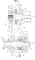
- Fig. 5 is a partial sectional view of the transfer case in accordance with the first exemplary embodiment of the present invention of Fig. 4 showing an enlarged sectional view of a hydraulically actuated torque-coupling device in accordance with the preferred embodiment of the present invention;
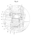
- Fig. 6 is an enlarged partial sectional view of a variable pressure relief valve assembly shown in a circle 'A' in Fig. 5;
- Fig. 7 is a graph showing an axial force applied upon a valve closure member by an electro-magnetic actuator as a function of "off-set" between a coil housing and an armature;
- Fig. 8 is a side view of a transfer case in accordance with a second exemplary embodiment of the present invention;
- Fig. 9 is a front view of the transfer case in accordance with the second exemplary embodiment of the present invention;
- Fig. 10 is a sectional view of the transfer case in accordance with the second exemplary embodiment of the present invention taken along lines X-X in Fig. 9;
- Fig. 11 is a partial sectional view of the transfer case in accordance with the second exemplary embodiment of the present invention of Fig. 10 showing an enlarged sectional view of the hydraulically actuated torque-coupling device in accordance with the preferred embodiment of the present invention.
- The preferred embodiments of the present invention will now be described with the reference to accompanying drawings.
- Fig. 1 schematically depicts a
drivetrain 1 of an all-wheel drive (AWD) or four-wheel drive (4WD) motor vehicle in accordance with the present invention. TheAWD drivetrain 1 comprises an internal combustion engine 2 (shown in phantom line) mounted to a front end of the motor vehicle and coupled to a transmission unit 4 (also shown in phantom line). - According to the first exemplary embodiment of the present invention, a
transfer case 20 is secured to the rear of the transmission unit 4. The transmission unit 4 is provided with an output shaft that is coupled to an input shaft (referred to below in Figs. 3 and 4 as 34) of thetransfer case 20. Thetransfer case 20 includes a rear output shaft oryoke 22 connected to a forward end of arear drive shaft 6 by means of a conventional universal joint coupling 8. The rearward end of therear drive shaft 6 is coupled to an input shaft oryoke 10 of arear differential 12 of a rear (primary) full-time axle assembly 11, by means of auniversal joint coupling 14. Therear differential 12 is adapted to provide torque from therear drive shaft 6 between rear wheels 15 (shown in phantom lines). - The
transfer case 20 is further provided with afront output yoke 24 that is coupled to a front output shaft (referred to below in Figs. 2 and 4 as 25) of thetransfer case 20 and connected to the rearward end of afront drive shaft 16 by means of a universaljoint coupling 18. Thefront drive shaft 16 has a forward end connected to an input shaft oryoke 26 of a frontdifferential unit 28 of a front (secondary) on-demand axle assembly 27 by means of auniversal joint coupling 29 and is adapted to divide torque received from thedrive shaft 16 between the vehicle front wheels 30 (shown in phantom lines). When configured as described, therear drive shaft 6 is adapted to rotate about an axis R, while thefront drive shaft 16 is adapted to rotate about an axis F. - The
transfer case 20 is provided for dividing the drive torque originating from the transmission unit 4 between the rear andfront propeller shafts rear propeller shaft 6. Thetransfer case 20 of the present invention is provided to selectively actuate the front, secondarydrive axle assembly 27 of the AWD motor vehicle. - As illustrated in Figs. 2-4, the
transfer case 20 comprises ahollow housing 32 secured to the transmission unit 4 (shown in Fig. 1), aninput shaft 34 drivingly coupled to the output shaft of the transmission unit 4, afront output shaft 25 drivingly coupled to thesecondary axle assembly 27 and selectively drivingly connectable to theinput shaft 34. Thehollow housing 32 generally comprises more than one section, the sections being held together by conventional fastening means, such as bolts. Theinput shaft 34 and thefront output shaft 25 are rotatably supported within thehousing 32 by appropriate support means, such as antifriction rolling bearing assemblies or the like and the openings through which theshafts housing 32 will be provided with appropriate seal assemblies, as are well known in the prior art. - Preferably, the
input shaft 34 is rotatably supported within thehousing 32 throughanti-friction bearings front output shaft 25 is rotatably supported within thehousing 32 through anti-friction bearing 33a and 33b. Likewise, all connections between theshafts - Torque transfer from the
input shaft 34 to thefront output shaft 25 occurs through adrive assembly 36. Preferably, thedrive assembly 36 is in the form of a chain drive assembly. Alternatively, gear drive assembly for transferring torque between theinput shaft 34 and thefront output shaft 25 may be employed. Thechain drive assembly 36 includes aninput sprocket 37 mounted about theinput shaft 34, anoutput sprocket 38 mounted about thefront output shaft 25, and anendless element 39 is provided to transmit a drive torque from theinput sprocket 37 to theoutput sprocket 38. Preferably, theendless element 39 is a chain. It will be appreciated that any other types of the endless torque-transmitting elements known in the prior art, such as a toothed belt, flat belt, V-belt, etc., may be employed. Theinput sprocket 37 is drivingly connected to theinput shaft 34 by any known means, such as through a spline connection. - The
output sprocket 38 is mounted about thefront output shaft 25 through a selectively operable, hydraulically actuated torque-couplingdevice 40 adapted to operatively and selectively actuate the front, secondarydrive axle assembly 27 of thedrivetrain 1 of the AWD motor vehicle only when needed, e.g. when slippage of thewheels 15 of the primary axle assembly 11 occurs. Specifically, the torque-couplingdevice 40 operatively and selectively connects theinput shaft 34 and thefront output shaft 25. More specifically, the torque-couplingdevice 40 of thetransfer case 20 according to the first exemplary embodiment of the present invention, is provided for selectively coupling theoutput sprocket 38 with hefront output shaft 25. - As illustrated in detail in Fig. 5, the torque-coupling
device 40 comprises a frictionclutch assembly 42 and a hydraulicclutch actuator 43 for selectively frictionally loading (actuating) the frictionclutch assembly 42. The frictionclutch assembly 42 is provided for engaging and disengaging theoutput sprocket 38, in turn positively coupled to theinput shaft 34, and thefront output shaft 25. The hydraulically actuated frictionclutch assembly 42 and the hydraulicclutch actuator 43 are disposed within ahollow casing 44 rotatably mounted within thehousing 32 and drivingly coupled to theoutput sprocket 38. Preferably, thecasing 44 is formed of twohalves - The friction
clutch assembly 42, well known in the prior art, includes sets of alternatingouter friction plates 42a andinner friction plates 42b. Conventionally, an outer circumference of theouter friction plates 42a is provided with projections that non-rotatably engages corresponding grooves formed in thecasing 44. Similarly, an inner circumference of theinner friction plates 42b is provided with projections that non-rotatably engage corresponding grooves formed in thefront output shaft 25. At the same time, both theouter friction plates 42a and theinner friction plates 42b are slideable in the axial direction. Theclutch plates 42a are adapted to frictionally engage theclutch plates 42b to form a torque coupling arrangement between thecasing 44 and thefront output shaft 25. - Furthermore, the hydraulic
clutch actuator 43 selectively actuates theclutch assembly 42. Preferably, the hydraulicclutch actuator 43 includes a speed sensitive positive displacementhydraulic pump 46 providing a pressurized hydraulic fluid, apiston assembly 48 for axially loading the frictionclutch assembly 42, and a variable pressurerelief valve assembly 50 for selectively controlling a discharge pressure of thepump 46 and, subsequently, the frictionclutch assembly 42. - The variable pressure
relief valve assembly 50 is operated by an electro-magnetic (preferably, solenoid) actuator electronically controlled by a coupling control module (CCM) 102 (shown in Fig. 1) based on one or more vehicle parameters ascontrol inputs 104, such as a vehicle speed, a wheel speed difference, vehicle yaw rate, a vehicle lateral acceleration, a steering angle, an engine throttle position, a brake application, an ice detection, a moisture detection, a vehicle driveline configuration, a vehicle yaw stability control system and an anti-lock brake system/traction control system (ABS/TCS). The CCM 102 is also connected to a source of an electric power supply, such as anelectric storage battery 106 mounted on the motor vehicle. When energized, the variable pressurerelief valve assembly 50 is capable of continuously modulating a discharge pressure of thepump 46 in a variable range from a minimum pressure to a maximum pressure, thereby selectively and variably controlling a drive torque applied from theinput shaft 34 to thefront output shaft 25 in a range from a minimum torque value to a maximum torque value. - The speed sensitive
hydraulic displacement pump 46 disposed within thecasing 44 actuates theclutch assembly 42 when the relative rotation between theinput shaft 34 and thefront output shaft 25 occurs. It will be appreciated that a hydraulic pressure generated by thepump 46 is substantially proportional to a rotational speed difference between theinput shaft 34 and thefront output shaft 25. Preferably, thehydraulic displacement pump 46 employed to provide pressurized hydraulic fluid to actuate theclutch assembly 42 is a bi-directional gerotor pump. Thegerotor pump 46 includes anouter ring member 46a, anouter rotor 46b, and aninner rotor 46c. Theinner rotor 46c drivingly coupled (i.e., keyed or splined) to thefront output shaft 25. Theinner rotor 46c has a plurality of external teeth that rotate concentrically relative to thefront output shaft 25. Theouter rotor 46b includes a plurality of internal teeth and has an outer circumferential edge surface that is rotatably supported within a circular internal bore formed in theouter ring member 46a. Preferably, theinner rotor 46c has one less tooth than theouter rotor 46b and when relative rotation between theinner rotor 46c and theouter ring member 46a occurs, it causes eccentric rotation of theouter rotor 46b, which can freely rotate within theouter ring member 46a eccentrically with respect to theinner rotor 46c, thus providing a series of decreasing and increasing volume fluid pockets by means of which fluid pressure is created. Therefore, when relative motion takes place between thefront output shaft 25 and theinput shaft 34, theinner rotor 46c of thegerotor pump 46 generates hydraulic fluid pressure. However, it will be appreciated that any other appropriate type of hydraulic pump generating the hydraulic pressure in response to the relative rotation between thefront output shaft 25 and theinput shaft 34 is within the scope of the present invention. - The
piston assembly 48 including a hydraulically actuatedpiston 48a disposed within apiston housing 48b, serves to compress theclutch assembly 42 and retard any speed differential between thefront output shaft 25 and theinput shaft 34. Pressurized hydraulic fluid to actuate thepiston 48a and engage theclutch assembly 42 is provided by thegerotor pump 46. In such an arrangement, when a speed difference between thefront output shaft 25 and theinput shaft 34 exists, the hydraulic fluid is drawn into thepump 46 through asuction passage 49. Thegerotor pump 46 pumps the pressurized fluid into apiston pressure chamber 48c defined between thepiston 48a and thepiston housing 48b to actuate theclutch assembly 42. As the speed difference increases, the pressure increases. The pressurized fluid in thepiston pressure chamber 48a creates an axial force upon the piston 28a for applying a compressive clutch engagement force on theclutch assembly 42, thereby transferring drive torque from theinput shaft 34 to thefront output shaft 25 through thecasing 44. The amount of torque transfer (i.e., the torque ratio or split) is progressive and continuously variable and is proportional to the magnitude of the clutch engagement force exerted by thepiston 48a on theclutch assembly 42 which, in turn, is a function of the fluid pressure within thepiston chamber 48a. Moreover, the magnitude of the fluid pressure withinpiston pressure chamber 48a, as delivered thereto by thehydraulic pump 46, is largely a function of the speed differential between thefront output shaft 25 and theinput shaft 34. - As noted above, in order to control the fluid pressure within the
piston pressure chamber 48a and, subsequently, the output torque distribution by the torque-couplingdevice 40 between the primary and auxiliarydrive axle assemblies 11 and 27 respectively, the hydraulicclutch actuator 43 is provided with the variable pressurerelief valve assembly 50. As illustrated in detail in Fig. 6, the variable pressurerelief valve assembly 50 according to the present invention is in the form of an electro-magnetic valve assembly mounted to thecasing 44 and comprises a pressurerelief check valve 52 controlled by an electro-magnetic actuator 54 that may be any appropriate electro-magnetic device well known in the art, such as a solenoid. - The
check valve 52 comprises afluid relief passageway 56 that is in fluid communication with thepiston pressure chamber 48c, a substantiallyconical valve seat 58 that is in open communication with thepassageway 56, and a spherical valve closure member 60 adapted to seat in thevalve seat 58 for sealing thefluid relief passageway 56. It will be appreciated that the valve closure member 60 may be in any appropriate form other than spherical, such as conical. Thevalve seat 58 is formed in an outer side surface of thehalf member 45b of thecasing 44. The valve closure member 60 is movable between a closed position when the valve closure member 60 engages the valve seat 58 (as shown in Fig. 6), and an open position when the valve closure member 60 is axially spaced from thevalve seat 58. - The electro-
magnetic actuator 54 comprises a substantiallyannular coil housing 62, a coil winding 64 wound about thecoil housing 62, and a substantiallyannular armature 72 axially movable in the direction toward and away from thevalve seat 58. Thearmature 52 is coaxial to the coil winding 64 and is radially spaced from thecoil housing 62, thus defining anair gap 76. Thecoil housing 62 is supported by thecasing 44 substantially coaxially to thefront output shaft 25 through acoil housing bushing 70 for rotation relative to thecasing 44. At the same time, thecoil housing 62 is non-rotatable relative tocasing 44. Thecoil housing 62 is preferably formed of a single or a plurality of laminations of a magnetically permeable material, such as conventional ferromagnetic materials. Thecoil housing bushing 70 is made of any appropriate non-magnetic material well known to those skilled in the art. - The
annular armature 72 is supported within anarmature bushing 74 for axial movement in the direction toward and away from thevalve seat 58. Thearmature bushing 74 is non-rotatably mounted to thecasing 44 by any appropriate means, such as press-fitting, adhesive bonding, etc. Preferably, thearmature bushing 74 is made of any appropriate non-magnetic material well known to those skilled in the art. - In the exemplary embodiment illustrated in Figs. 5 and 6, the
armature 72 is radially disposed outside thecoil housing 62 of the electro-magnetic actuator 54. Alternatively, thearmature 72 may be disposed within thecoil housing 62. - The valve closure member 60 is urged and held in place against the
valve seat 58 by anactuator plate 78. In turn, theactuator plate 78 is adapted to engage thearmature 72 of the electro-magnetic actuator 54 radially disposed outside thecoil housing 62 thereof. Preferably, theactuator plate 78 is in the shape of an annular segment and is made of any appropriate non-magnetic material well known to those skilled in the art. Furthermore, theactuator plate 78 is fastened to thearmature 72 by any appropriate means known in the art, such as threaded connectors, adhesive bonding, etc. - When electrical current is supplied to the coil winding 64, a magnetic flux is caused to flow through the
armature 72. The magnetic flux creates an axial force that axially displaces thearmature 72 relative to thecoil housing 62. Thearmature 72 urges the valve closure member 60 upon thevalve seat 58 with a predetermined axial retaining force that is a function of the electrical current supplied to the coil winding 64. It will be appreciated by those skilled in the art that the pressurized hydraulic fluid will not flow through thepressure relief valve 52 until the hydraulic pressure generated by thegerotor pump 46 results in a reaction force larger than the axial retaining force exerted to thearmature 72 by the magnetic flux generated by the coil winding 64, thereby pushing the valve closure member 60 out of thevalve seat 58. Therefore, such an arrangement creates a relief valve with a release pressure that is a function of the current supplied to the coil winding 64, and provides a predetermined pressure limit in the hydraulic system. Thus, the variable pressurerelief valve assembly 50 selectively sets the release pressure of thepressure relief valve 52 as a function of the electrical current supplied to the coil winding 64 and, subsequently, defines the magnitude of the pressure within thepiston pressure chamber 48c. - It will be appreciated by those skilled in the art that the
armature 72 may have any appropriate shape in the cross-section. Preferably, as illustrated in the exemplary embodiment of Fig. 6, thearmature 72 has a generally U-shaped cross-section with magnetic poles facing thecoil housing 62, similar to those used in reluctance electric motors. Moreover, the mutual geometric arrangement of thearmature 72 and thecoil housing 62 is such as to maintain a substantially constant axial force applied upon the valve closure member 60 by the electro-magnetic actuator 54 as it moves from its closed to open position. This is achieved by maintaining a proper "off-set" between thearmature 72 and the coil housing 62 (and, consequently, the coil winding 64). The term "off-set" is determined here as an amount of misalignment between thearmature 72 and thecoil housing 62, or a distance k between anoutward face 62' of thecoil housing 62 and an outward face 72' of thearmature 72, as illustrated in Fig. 6. - Fig. 7 depicts a graph showing the axial force applied upon the valve closure member 60 by the electro-
magnetic actuator 54 as a function of the "off-set" distance k while a constant magnitude of electric current is supplied to the coil winding 64. The graph is in the form of a curved line F having a substantially "flat" section FC wherein the axial force varies insignificantly with respect to the "off-set" distance k. However, operation outside of this section FC results in an abrupt change of the axial force. Thus, while the electro-magnetic actuator 54 of therelief valve assembly 50 is operated in the "flat" section FC, the axial force applied upon the valve closure member 60 by the electro-magnetic actuator 54 is substantially constant as it moves from its closed to open position, and is a function of the electrical current supplied to the coil winding 64. On the other hand, operation outside of this "flat" section FC results in the axial force being a function of both the current and the "off-set" distance k that would make control of the variable pressure relief valve more difficult requiring a closed loop feedback as to the valve's "off-set". Other, more traditional solenoid pole designs do not provide this "flat" section in the axial force versus "off-set" distance curve. - For the above described reason, the electro-
magnetic actuator 54 in accordance with the preferred embodiment of the present invention is arranged to provide the "off-set" distance k between thecoil housing 62 and thearmature 72 within the "flat" section FC of the axial force versus "off-set" distance curve so as to ensure that the axial force applied upon the valve closure member 60 by the electro-magnetic actuator 54 is substantially constant as it moves from its closed to open position, and is a function only of the electrical current supplied to the coil winding 64. - When a maximum current is applied to the coil winding 64 of the
solenoid actuator 54, the retaining force of the pressurerelief check valve 52 is at its maximum, thus a maximum release pressure is provided by the pressurerelief check valve 52. In this configuration, the maximum pressure attainable within thepiston pressure chamber 48c is sufficient to fully actuate the frictionclutch assembly 42 which results in fully engaging the friction clutch pack of the torque-couplingdevice 40, and the limited slip feature is in the fully "ON" condition. - The pressure limit of the pressure
relief check valve 52, i.e. the release pressure of the pressurerelief check valve 52, can be adjusted by controlling the current applied to the coil winding 64 of the electro-magnetic actuator 54. - As the less current is applied to the coil winding 64, the less axial retaining force is exerted to the pressure
relief check valve 52, thus the less is the release pressure provided by the pressurerelief check valve 52. This results in an adjustment mechanism for lowering the maximum system pressure attainable within thepiston pressure chamber 48c. - When a minimum current is applied to the coil winding 64 of the
solenoid actuator 54, the retaining force of the pressurerelief check valve 52 is at its minimum, thus a minimum release pressure is provided by the pressurerelief check valve 52. In this configuration, the limited slip feature is in the fully "OFF" condition in that the maximum pressure which can be obtained in thepiston pressure chamber 48c is not high enough to engage the frictionclutch assembly 42, thus effectively disabling theclutch assembly 42 and essentially disconnecting the torque-couplingdevice 40. - In between the "ON" and "OFF" conditions of the torque-coupling
device 40, the release pressure of the pressurerelief check valve 52 may be set at any value between these limits by modulating the current applied to the coil winding 64 of thesolenoid actuator 54. This provides the torque-couplingdevice 40 with an infinitely variable maximum pressure limit in which the amount of the limited slip available to the torque-couplingdevice 40 can be limited and optimized to match various vehicle operating conditions. This provides an opportunity to dynamically control the hydraulic pressure for traction enhancement. For example, if the release pressure is set at a low value, a control system can be used to sense wheel speeds or speed differences and allow for increased hydraulic pressure. The increase in pressure available may be a function of the speed difference. This will result in an optimized amount of limited slip between the fully "ON" and "OFF" conditions. - During normal operation, the torque-coupling
device 40 is in the "OFF" position as the minimum current is applied to the variable pressurerelief valve assembly 50, thus disabling theclutch assembly 42. However, if, for example, thewheels 15 of the primary axle assembly 11 loses traction, the CCM 102 issues a signal to the variable pressurerelief valve assembly 50 to set the torque-couplingdevice 40 in the "ON" position. This will set the maximum release pressure provided by the pressurerelief check valve 52. The differential speed between theinput shaft 34 and thefront output shaft 25 will result in thehydraulic pump 46 delivering pressurized fluid to thepiston 48a, and the frictionclutch assembly 42 will be engaged. With theclutch assembly 42 engaged, thewheels 30 of thesecondary axle assembly 27 of the vehicle will be driven. - Therefore, in accordance with the present invention, the AWD system is actuated only when the
vehicle input sensors 104 sense a reduction in traction at therear wheels 15. Also, the AWD system may by actuated manually by a vehicle operator. - Moreover, when energized, the solenoid-operated
valve assembly 50 is capable of modulating a pump discharge pressure in a variable range from a minimum pressure to a maximum pressure, thereby selectively and variably controlling a drive torque applied to the wheels of the auxiliary axle assembly in a range from a minimum torque value to a maximum torque value. Thus, the torque coupling in accordance with the present invention allows infinitely variable torque distribution between the primary axle assembly and the secondary axle assembly. - Figs. 8-11 of the drawings depict a second exemplary embodiment of the transfer case of the present invention generally designated with the
reference numeral 120. Components, which are unchanged from, or function in the same way as in the first exemplary embodiment depicted in Figs. 1-7 are labeled with the same reference numerals, sometimes without describing detail since similarities between the corresponding parts in the two embodiments will be readily perceived by the reader. - As illustrated in Figs. 8-10, the
transfer case 120 of the second exemplary embodiment of the present invention comprises ahollow housing 32 secured to the transmission unit 4, aninput shaft 34 drivingly coupled to the output shaft of the transmission unit, afront output shaft 25 drivingly coupled to thesecondary axle assembly 27 and selectively drivingly connectable to theinput shaft 34. Theinput shaft 34 and thefront output shaft 25 are rotatably supported within thehousing 32 by appropriate support means. - Torque transfer from the
input shaft 34 to thefront output shaft 25 occurs through adrive assembly 36. Preferably, thedrive assembly 36 is in the form of a chain drive assembly. Thechain drive assembly 36 includes aninput sprocket 37 mounted about theinput shaft 34, anoutput sprocket 38 mounted about thefront output shaft 25, and anendless element 39 is provided to transmit a drive torque from theinput sprocket 37 to theoutput sprocket 38. Theoutput sprocket 38 is drivingly connected to thefront output shaft 25 by any known means, such as through a spline connection. - The
input sprocket 37 is mounted about theinput shaft 34 through a selectively operable, hydraulically actuated torque-couplingdevice 40 adapted to operatively and selectively actuate the front, secondarydrive axle assembly 27 of the drivetrain of the AWD motor vehicle only when needed, e.g. when slippage of thewheels 15 of the primary axle assembly 11 occurs. Specifically, the torque-couplingdevice 40 operatively and selectively connects theinput shaft 34 and thefront output shaft 25. More specifically, the torque-couplingdevice 40 of thetransfer case 120 according to the second exemplary embodiment of the present invention is provided for selectively coupling theinput shaft 34 with theinput sprocket 37. Preferably, the hydraulically actuated torque-couplingdevice 40 of thetransfer case 120 according to the second exemplary embodiment of the present invention is substantially identical to the torque-coupling device of thetransfer case 20 according to the first exemplary embodiment of the present invention. - As further illustrated in Fig. 11, the torque-coupling
device 40 comprises a frictionclutch assembly 42 and a hydraulicclutch actuator 43 for selectively frictionally loading (actuating) the frictionclutch assembly 42. The frictionclutch assembly 42 is provided for engaging and disengaging theinput sprocket 37 to/from thefront output shaft 25. The hydraulically actuated frictionclutch assembly 42 and the hydraulicclutch actuator 43 are disposed within acasing 44 rotatably mounted within thehousing 32 and drivingly coupled to theinput sprocket 37. - The hydraulic
clutch actuator 43 selectively actuates theclutch assembly 42. Preferably, the hydraulicclutch actuator 43 includes a speed sensitive positive displacementhydraulic pump 46 providing a pressurized hydraulic fluid, apiston assembly 48 for axially loading the frictionclutch assembly 42, and a variable pressurerelief valve assembly 50 for selectively controlling a discharge pressure of thepump 46 and, subsequently, the frictionclutch assembly 42. Preferably, the frictionclutch assembly 42 and the hydraulicclutch actuator 43 of the second exemplary embodiment of the present invention are unchanged from and function generally in the same way as in the first exemplary embodiment depicted in Figs. 5-7. - Therefore, the selectively operable transfer case for the AWD motor vehicles in accordance with the present invention represents a novel arrangement of the hydraulically actuated AWD transfer case provided with a variable pressure relief valve assembly for allowing selective actuation of the auxiliary drive axle assembly and infinitely variable torque distribution between the primary and secondary drive axle assemblies of the AWD motor vehicle.
- The foregoing description of the preferred embodiments of the present invention has been presented for the purpose of illustration in accordance with the provisions of the Patent Statutes. It is not intended to be exhaustive or to limit the invention to the precise forms disclosed. Obvious modifications or variations are possible in light of the above teachings. The embodiments disclosed hereinabove were chosen in order to best illustrate the principles of the present invention and its practical application to thereby enable those of ordinary skill in the art to best utilize the invention in various embodiments and with various modifications as are suited to the particular use contemplated, as long as the principles described herein are followed. Thus, changes can be made in the above-described invention without departing from the intent and scope thereof. It is also intended that the scope of the present invention be defined by the claims appended thereto.
Claims (12)
- A transfer case for a motor vehicle having a selectively, on-demand actuatable secondary drive axle, said transfer case comprising:an input shaft and an input member mounted about said input shaft;an output shaft spaced from said input shaft and an output member mounted about said output shaft, said output shaft drivingly connected to said secondary drive axle;a mechanism for transmitting torque from said input member to said output member; anda torque-coupling device for selectively drivingly connecting one of said input shaft to said input member and said output member to said output shaft, said torque coupling device comprising:a hollow casing;a friction clutch assembly comprising at least one first member coupled to rotate with one of said input member and said output member and at least one second member coupled to rotate with one of said input shaft and said output shaft, said first and second members being frictionally engageable with one another; anda hydraulic clutch actuator for selectively frictionally loading said friction clutch assembly, said hydraulic clutch actuator comprising:a hydraulic pump disposed within said hollow casing to generate a hydraulic pressure to frictionally load said friction clutch assembly; anda variable pressure relief valve assembly fluidly communicating with said hydraulic pump to selectively control said hydraulic pressure.
- The transfer case as defined in claim 1, wherein said variable pressure relief valve assembly includes a valve closure member, a valve seat complementary to said valve closure member and an electro-magnetic actuator for engaging said valve closure member and urging thereof against said valve seat so as to selectively vary a release pressure of said pressure relief valve assembly based on a magnitude of an electric current supplied to said electro-magnetic actuator, said valve closure member is movable between a closed position when said valve closure member engages said valve seat and an open position when said valve closure member is axially spaced from said valve seat.
- The transfer case as defined in claim 2, wherein said electro-magnetic actuator including a coil winding wound about a coil housing mounted to said clutch casing and an armature radially spaced from said coil housing and axially movable relative thereto in response to a magnetic flux generated by said coil winding when said electrical current is supplied thereto, said armature engages said valve closure member and urges thereof against said valve seat with an axial force determined by said magnitude of said electric current for selectively setting up said release pressure of said valve closure member.
- The transfer case as defined in claim 3, wherein said coil housing is rotatably mounted to an outer peripheral surface of said clutch casing coaxially to an axis of rotation of said casing, and wherein said armature is non-rotatably coupled to said clutch casing, disposed outside said coil housing of said electro-magnetic actuator, substantially annular in shape, and mounted substantially coaxially to said coil housing.
- The transfer case as defined in claim 1, wherein each of said input and members is in the form of a sprocket, and wherein said mechanism for transmitting torque from said input member to said output member is in the form of an endless element transmitting torque from said input sprocket to said output sprocket, and wherein said friction clutch assembly is a friction clutch pack including a plurality of inner friction plates coupled to rotate with said input shaft and a plurality of outer friction plate coupled to rotate with said casing, said casing is drivingly coupled to said output shaft, said friction plates being frictionally engageable with one another, and wherein said casing is formed integrally with said output shaft, and wherein said casing houses said friction clutch assembly and said a hydraulic clutch actuator.
- The transfer case as defined in claim 1, wherein said hydraulic pump is a positive displacement hydraulic pump disposed within said casing, said hydraulic pump generates a hydraulic pressure in response to relative rotation between said casing and at least one of said output shafts, and wherein said pump is a bi-directional gerotor pump.
- The transfer case as defined in claim 1, wherein said variable pressure relief valve assembly is adapted to selectively set a maximum hydraulic pressure generated by said hydraulic pump between a maximum release pressure that enables complete actuation of said friction clutch assembly and a minimum release pressure that prevents actuation of said friction clutch assembly, wherein said maximum hydraulic pressure generated by said hydraulic pump is adjustable between said minimum release pressure and said maximum release pressure so as to enable partial actuation of said friction clutch assembly.
- The transfer case as defined in claim 1, wherein said hydraulic clutch actuator further including a piston assembly disposed within said clutch casing between said pump and said clutch assembly and defining a pressure chamber, wherein said variable pressure relief valve assembly selectively controls a maximum hydraulic pressure attainable within said pressure chamber, wherein said variable pressure relief valve assembly selectively controls said maximum pressure attainable within said pressure chamber between a maximum release pressure and a minimum release pressure, and wherein said minimum release pressure is at a level that prevents actuation of said friction clutch assembly, and wherein said maximum release pressure is at a level that enables complete actuation of said friction clutch assembly, and wherein said maximum hydraulic pressure attainable within said pressure chamber is adjustable between said minimum release pressure and said maximum release pressure so as to enable partial actuation of said friction clutch assembly.
- The transfer case as defined in claim 3, wherein said armature has a substantially U-shaped cross-section, wherein said coil housing is rotatably mounted to said casing, and wherein said armature is off-set from said coil housing to a distance that ensures that said axial force applied upon said valve closure member by said electro-magnetic actuator is substantially constant as said valve closure member moves from said closed position to said open position and said axial force is a function only of said electrical current supplied to said coil winding.
- The transfer case as defined in claim 1, wherein said variable pressure relief valve assembly selective controls said hydraulic pressure generated by hydraulic pump in response to at least one vehicle parameter selected from the group consisting of a vehicle speed, a wheel speed difference, a vehicle yaw rate, a steering angle, an engine throttle position, a vehicle lateral acceleration, a brake application, an ice detection, a moisture detection, a driveline configuration, an anti-lock brake system/traction control system actuation, and a vehicle yaw stability control system actuation.
- The transfer case as defined in claim 1, wherein said housing is fastened to one of an axle housing of said secondary drive axle assembly or a housing of a power transfer unit of said all-wheel-drive motor vehicle, and wherein said input shaft is drivingly coupled to a propeller shaft of said motor vehicle and said output shaft is a drive pinion shaft of said secondary drive axle assembly.
- The transfer case as defined in claim 2, wherein said valve seat is provided on said clutch casing.
Applications Claiming Priority (1)
| Application Number | Priority Date | Filing Date | Title |
|---|---|---|---|
| US10/986,793 US20060105883A1 (en) | 2004-11-15 | 2004-11-15 | Transfer case with variably controlled torque coupling device |
Publications (2)
| Publication Number | Publication Date |
|---|---|
| EP1666299A2 true EP1666299A2 (en) | 2006-06-07 |
| EP1666299A3 EP1666299A3 (en) | 2006-11-02 |
Family
ID=35840267
Family Applications (1)
| Application Number | Title | Priority Date | Filing Date |
|---|---|---|---|
| EP05109917A Withdrawn EP1666299A3 (en) | 2004-11-15 | 2005-10-24 | Transfer case with variably controlled torque coupling device |
Country Status (3)
| Country | Link |
|---|---|
| US (1) | US20060105883A1 (en) |
| EP (1) | EP1666299A3 (en) |
| AU (1) | AU2005232294A1 (en) |
Cited By (1)
| Publication number | Priority date | Publication date | Assignee | Title |
|---|---|---|---|---|
| EP3418098A4 (en) * | 2016-03-16 | 2019-10-02 | Xuzhou Heavy Machinery Co., Ltd. | ENGINE BRIDGE ASSEMBLY AND INDUSTRIAL VEHICLE |
Families Citing this family (9)
| Publication number | Priority date | Publication date | Assignee | Title |
|---|---|---|---|---|
| US9126598B2 (en) * | 2006-06-05 | 2015-09-08 | Deere & Company | Power management for infinitely variable transmission (IVT) equipped machines |
| US7853382B2 (en) * | 2006-09-29 | 2010-12-14 | Deere & Company | Loader boom control system |
| US8005589B2 (en) * | 2008-06-20 | 2011-08-23 | GM Global Technology Operations LLC | Method and system for addressing improper towing of a vehicle |
| EP3099569B1 (en) * | 2014-01-31 | 2021-01-27 | BorgWarner Sweden AB | A hydraulic system for a vehicle |
| US9579975B2 (en) * | 2014-05-05 | 2017-02-28 | Arvinmeritor Technology, Llc | System and method of controlling a drive axle system |
| US10330183B2 (en) | 2015-06-11 | 2019-06-25 | Magna Powertrain Of America, Inc. | Two-speed active transfer case |
| DE102020125415A1 (en) * | 2020-09-29 | 2022-03-31 | Deere & Company | Arrangement for releasing a coupling connection of a hydraulic quick coupler |
| JP7444087B2 (en) * | 2021-01-21 | 2024-03-06 | トヨタ自動車株式会社 | Hybrid vehicle control device |
| CN115978104A (en) * | 2023-03-21 | 2023-04-18 | 中国第一汽车股份有限公司 | Transfer case and have its vehicle |
Family Cites Families (17)
| Publication number | Priority date | Publication date | Assignee | Title |
|---|---|---|---|---|
| US4185723A (en) * | 1976-12-13 | 1980-01-29 | Borg-Warner Corporation | Automatic four-wheel drive transfer case |
| JPS56138019A (en) * | 1980-03-31 | 1981-10-28 | Aisin Warner Ltd | Automatic two-wheel/four-wheel drive change-over mechanism for four-wheel drive vehicle |
| US4762021A (en) * | 1983-09-27 | 1988-08-09 | Tochigifujisangyo Kabushikigaisha | Transfer case for four-wheel-drive vehicles |
| DE3621225C1 (en) * | 1986-06-25 | 1987-05-27 | Daimler Benz Ag | Control device for temporarily switching a vehicle drive from a single-axis drive via a permanently driven vehicle axis to a two-axis drive |
| US5334116A (en) * | 1992-12-31 | 1994-08-02 | Dana Corporation | All wheel drive transfer case having two wheel overdrive |
| JP3384167B2 (en) * | 1995-02-15 | 2003-03-10 | 日産自動車株式会社 | Transfer hydraulic control system for four-wheel drive vehicles |
| US5655983A (en) * | 1995-04-28 | 1997-08-12 | Dana Corporation | Hydromechanical system for limiting differential speed between differentially rotating members |
| US5704863A (en) * | 1996-07-01 | 1998-01-06 | New Venture Gear, Inc. | Two-speed transfer case with on-demand torque control having a coupling pump and a supply pump |
| US6112874A (en) * | 1999-01-12 | 2000-09-05 | New Venture Gear, Inc. | Hydromechanical coupling with torque-limiting and temperature-sensitive unloading features |
| US6626787B2 (en) * | 2001-04-02 | 2003-09-30 | New Venture Gear, Inc. | On-demand all-wheel drive system |
| US6953411B2 (en) * | 2001-04-02 | 2005-10-11 | Magna Drivetrain Of America, Inc. | Electronically-tuned hydromechanical coupling |
| US6733411B1 (en) * | 2002-01-31 | 2004-05-11 | Dana Corporation | Electronically controlled hydraulic actuator for limited slip differential assembly |
| US6692396B1 (en) * | 2002-02-27 | 2004-02-17 | Torque-Traction Technologies, Inc. | Solenoid actuated variable pressure relief valve assembly for limited slip differential assembly |
| US6699151B2 (en) * | 2002-03-27 | 2004-03-02 | Torque-Traction Technologies, Inc. | Solenoid valve controlled all-wheel drive hydraulic coupling assembly |
| US6725989B1 (en) * | 2002-04-24 | 2004-04-27 | Torque-Traction Technologies, Inc. | Variably controlled torque coupling device for on-demand all-wheel drive drivetrains |
| US7021445B2 (en) * | 2003-07-28 | 2006-04-04 | Magna Powertrain, Inc. | Low power hydraulic clutch actuation systems |
| US7004873B2 (en) * | 2004-01-22 | 2006-02-28 | Magna Powertrain, Inc. | Transfer case with electrohydraulic clutch actuator |
-
2004
- 2004-11-15 US US10/986,793 patent/US20060105883A1/en not_active Abandoned
-
2005
- 2005-10-24 EP EP05109917A patent/EP1666299A3/en not_active Withdrawn
- 2005-11-11 AU AU2005232294A patent/AU2005232294A1/en not_active Abandoned
Cited By (1)
| Publication number | Priority date | Publication date | Assignee | Title |
|---|---|---|---|---|
| EP3418098A4 (en) * | 2016-03-16 | 2019-10-02 | Xuzhou Heavy Machinery Co., Ltd. | ENGINE BRIDGE ASSEMBLY AND INDUSTRIAL VEHICLE |
Also Published As
| Publication number | Publication date |
|---|---|
| AU2005232294A1 (en) | 2006-06-01 |
| EP1666299A3 (en) | 2006-11-02 |
| US20060105883A1 (en) | 2006-05-18 |
Similar Documents
| Publication | Publication Date | Title |
|---|---|---|
| US6725989B1 (en) | Variably controlled torque coupling device for on-demand all-wheel drive drivetrains | |
| US6699151B2 (en) | Solenoid valve controlled all-wheel drive hydraulic coupling assembly | |
| US7857723B2 (en) | Transaxle unit with integrated power take-off unit and torque coupling device | |
| US6692396B1 (en) | Solenoid actuated variable pressure relief valve assembly for limited slip differential assembly | |
| US6733411B1 (en) | Electronically controlled hydraulic actuator for limited slip differential assembly | |
| US7210566B2 (en) | Friction coupling assembly with auxiliary clutch control of fluid pump | |
| US6513615B2 (en) | Full-time all-wheel drive power take-off unit for motor vehicle | |
| US7878933B2 (en) | Hydraulic coupling with disconnect pump clutch | |
| US20010035323A1 (en) | Active control of a hydra-mechanical traction control device | |
| EP1527938A2 (en) | Electronically-controlled rear drive module for all-wheel drive vehicle | |
| WO2008033180A1 (en) | Coupling assembly | |
| US7452301B2 (en) | Externally actuated torque coupling for drivetrain | |
| US7077779B2 (en) | Solenoid actuated variable pressure relief valve assembly for torque transfer assembly | |
| EP1666299A2 (en) | Transfer case with variably controlled torque coupling device | |
| US7448482B2 (en) | Electro-magnetic actuator for torque coupling with variable pressure-relief valve | |
| US7353928B2 (en) | Torque coupling assembly with venting passage | |
| US8763777B2 (en) | Hydraulic coupling | |
| US20080103009A1 (en) | Self-contained torque-coupling assembly | |
| US7413066B2 (en) | Hydraulically controlled torque coupling device |
Legal Events
| Date | Code | Title | Description |
|---|---|---|---|
| PUAI | Public reference made under article 153(3) epc to a published international application that has entered the european phase |
Free format text: ORIGINAL CODE: 0009012 |
|
| AK | Designated contracting states |
Kind code of ref document: A2 Designated state(s): AT BE BG CH CY CZ DE DK EE ES FI FR GB GR HU IE IS IT LI LT LU LV MC NL PL PT RO SE SI SK TR |
|
| AX | Request for extension of the european patent |
Extension state: AL BA HR MK YU |
|
| PUAL | Search report despatched |
Free format text: ORIGINAL CODE: 0009013 |
|
| AK | Designated contracting states |
Kind code of ref document: A3 Designated state(s): AT BE BG CH CY CZ DE DK EE ES FI FR GB GR HU IE IS IT LI LT LU LV MC NL PL PT RO SE SI SK TR |
|
| AX | Request for extension of the european patent |
Extension state: AL BA HR MK YU |
|
| RIC1 | Information provided on ipc code assigned before grant |
Ipc: B60K 17/344 20060101ALI20060927BHEP Ipc: B60K 17/346 20060101AFI20060301BHEP |
|
| 17P | Request for examination filed |
Effective date: 20070319 |
|
| 17Q | First examination report despatched |
Effective date: 20070420 |
|
| AKX | Designation fees paid |
Designated state(s): AT BE BG CH CY CZ DE DK EE ES FI FR GB GR HU IE IS IT LI LT LU LV MC NL PL PT RO SE SI SK TR |
|
| STAA | Information on the status of an ep patent application or granted ep patent |
Free format text: STATUS: THE APPLICATION IS DEEMED TO BE WITHDRAWN |
|
| 18D | Application deemed to be withdrawn |
Effective date: 20080501 |