EP1666168A1 - Tool for removing foreign object in pipe line - Google Patents
Tool for removing foreign object in pipe line Download PDFInfo
- Publication number
- EP1666168A1 EP1666168A1 EP04788181A EP04788181A EP1666168A1 EP 1666168 A1 EP1666168 A1 EP 1666168A1 EP 04788181 A EP04788181 A EP 04788181A EP 04788181 A EP04788181 A EP 04788181A EP 1666168 A1 EP1666168 A1 EP 1666168A1
- Authority
- EP
- European Patent Office
- Prior art keywords
- duct
- insertion tube
- removal instrument
- foreign body
- body removal
- Prior art date
- Legal status (The legal status is an assumption and is not a legal conclusion. Google has not performed a legal analysis and makes no representation as to the accuracy of the status listed.)
- Withdrawn
Links
Images


Classifications
-
- A—HUMAN NECESSITIES
- A61—MEDICAL OR VETERINARY SCIENCE; HYGIENE
- A61B—DIAGNOSIS; SURGERY; IDENTIFICATION
- A61B17/00—Surgical instruments, devices or methods
- A61B17/22—Implements for squeezing-off ulcers or the like on inner organs of the body; Implements for scraping-out cavities of body organs, e.g. bones; for invasive removal or destruction of calculus using mechanical vibrations; for removing obstructions in blood vessels, not otherwise provided for
-
- B—PERFORMING OPERATIONS; TRANSPORTING
- B08—CLEANING
- B08B—CLEANING IN GENERAL; PREVENTION OF FOULING IN GENERAL
- B08B9/00—Cleaning hollow articles by methods or apparatus specially adapted thereto
- B08B9/02—Cleaning pipes or tubes or systems of pipes or tubes
- B08B9/027—Cleaning the internal surfaces; Removal of blockages
- B08B9/04—Cleaning the internal surfaces; Removal of blockages using cleaning devices introduced into and moved along the pipes
-
- B—PERFORMING OPERATIONS; TRANSPORTING
- B08—CLEANING
- B08B—CLEANING IN GENERAL; PREVENTION OF FOULING IN GENERAL
- B08B9/00—Cleaning hollow articles by methods or apparatus specially adapted thereto
- B08B9/02—Cleaning pipes or tubes or systems of pipes or tubes
- B08B9/027—Cleaning the internal surfaces; Removal of blockages
- B08B9/04—Cleaning the internal surfaces; Removal of blockages using cleaning devices introduced into and moved along the pipes
- B08B9/043—Cleaning the internal surfaces; Removal of blockages using cleaning devices introduced into and moved along the pipes moved by externally powered mechanical linkage, e.g. pushed or drawn through the pipes
- B08B9/045—Cleaning the internal surfaces; Removal of blockages using cleaning devices introduced into and moved along the pipes moved by externally powered mechanical linkage, e.g. pushed or drawn through the pipes the cleaning devices being rotated while moved, e.g. flexible rotating shaft or "snake"
-
- A—HUMAN NECESSITIES
- A61—MEDICAL OR VETERINARY SCIENCE; HYGIENE
- A61B—DIAGNOSIS; SURGERY; IDENTIFICATION
- A61B17/00—Surgical instruments, devices or methods
- A61B17/22—Implements for squeezing-off ulcers or the like on inner organs of the body; Implements for scraping-out cavities of body organs, e.g. bones; for invasive removal or destruction of calculus using mechanical vibrations; for removing obstructions in blood vessels, not otherwise provided for
- A61B17/22004—Implements for squeezing-off ulcers or the like on inner organs of the body; Implements for scraping-out cavities of body organs, e.g. bones; for invasive removal or destruction of calculus using mechanical vibrations; for removing obstructions in blood vessels, not otherwise provided for using mechanical vibrations, e.g. ultrasonic shock waves
- A61B17/22012—Implements for squeezing-off ulcers or the like on inner organs of the body; Implements for scraping-out cavities of body organs, e.g. bones; for invasive removal or destruction of calculus using mechanical vibrations; for removing obstructions in blood vessels, not otherwise provided for using mechanical vibrations, e.g. ultrasonic shock waves in direct contact with, or very close to, the obstruction or concrement
-
- A—HUMAN NECESSITIES
- A61—MEDICAL OR VETERINARY SCIENCE; HYGIENE
- A61B—DIAGNOSIS; SURGERY; IDENTIFICATION
- A61B17/00—Surgical instruments, devices or methods
- A61B17/32—Surgical cutting instruments
- A61B17/3205—Excision instruments
- A61B17/3207—Atherectomy devices working by cutting or abrading; Similar devices specially adapted for non-vascular obstructions
- A61B17/320758—Atherectomy devices working by cutting or abrading; Similar devices specially adapted for non-vascular obstructions with a rotating cutting instrument, e.g. motor driven
-
- A—HUMAN NECESSITIES
- A61—MEDICAL OR VETERINARY SCIENCE; HYGIENE
- A61M—DEVICES FOR INTRODUCING MEDIA INTO, OR ONTO, THE BODY; DEVICES FOR TRANSDUCING BODY MEDIA OR FOR TAKING MEDIA FROM THE BODY; DEVICES FOR PRODUCING OR ENDING SLEEP OR STUPOR
- A61M25/00—Catheters; Hollow probes
- A61M2025/0019—Cleaning catheters or the like, e.g. for reuse of the device, for avoiding replacement
Definitions
- the present invention relates to an intraductal foreign body removal instrument used to remove fibrous foreign bodies out of ducts. More particularly, it relates to an intraductal foreign body removal instrument which can be suitably used as a catheter to remove fibrous occluding objects and the like out of intravital ducts such as blood vessels.
- JP10-175705A discloses an intraductal foreign body removal instrument, comprising a gripping mechanism which is attached to a main unit (foreign body removal instrument) to grip, for example, foreign bodies in a duct using claws, wherein a tip of a pull-up wire is attached to the main unit, and the other end of the wire is attached to a wire winder installed outside the duct.
- the main unit is fed into a duct until it gets close to a constriction caused by foreign bodies.
- the gripping mechanism is brought close to the foreign bodies and the claws are closed to grip the foreign bodies.
- the pull-up wire is wound by the winder, taking the main unit out of the duct, and thereby removing the foreign bodies.
- an intraductal foreign body removal instrument comprising a gripping mechanism, as is the case with the technique disclosed in JP10-175705A, involves feeding the gripping mechanism itself composed of a large number of parts into a duct, which increases resistance in the duct. Consequently, for example, elbows or similar bends increase resistance, causing a problem of limited feed. Also, to position the gripping mechanism in the duct and remove (grip) foreign bodies, it is necessary to control relative distance from the foreign bodies by subtly adjusting an actuator. This presents a problem of increased time required to remove the foreign bodies.
- a duct has a small diameter allowing a limited work area
- limited space may be available for use to open and close the gripping mechanism.
- the gripping mechanism itself cannot be fed to a constriction in the duct due to its size.
- Possible circumstances where a duct has a small diameter allowing a limited work area include an intravital duct from which foreign bodies are removed. When removing foreign bodies out of an intravital duct, which is small in diameter and twists turns intricately, without damaging body tissues, the above problems become more prominent.
- a catheter for example, is used to remove foreign bodies out of intravital ducts.
- the present invention has been made in view of the above problems and has an object to provide an intraductal foreign body removal instrument which can remove fibrous foreign bodies clogging elbows, narrowed parts, or other constrictions of pipes or similar ducts without requiring a large, complex equipment configuration.
- an intraductal foreignbody removal instrument which can be suitably used as a catheter to be inserted in intravital ducts such as blood vessels to remove fibrous occluding obj ects out of the duct.
- the present invention as set forth in claim 1 provides an intraductal foreign body removal instrument which removes fibrous foreign bodies out of a duct, characterized by comprising: a flexible insertion tube inserted in the duct; a wire made of flexible wire material and inserted in the insertion tube; and a rotating device which rotates the wire in the insertion tube.
- the invention set forth in claim 1 allows the insertion tube and the wire in the insertion tube to be reduced in diameter, making it possible to insert them easily in a duct.
- that side (hereinafter referred to as a free end side) of the intraductal foreign body removal instrument which is inserted in a duct is not equipped with any special mechanism (such as the gripping mechanism of the conventional example).
- the free end side is fed into the duct, but it does not encounter much resistance because it is only the insertion tube (and the wire in the insertion tube). Consequently, even elbows and similar bends, for example, do not offer high resistance.
- the instrument can be used even in small-diameter ducts. Also, feed limits of the intraductal foreign body removal instrument can be increased.
- fibrous foreign bodies can be tangled around the free end side of the intraductal foreign body removal instrument by rotating the wire by the rotating device. After the fibrous foreign bodies are tangled, they can be removed as the intraductal foreign body removal instrument is retrieved from the duct through insertion position.
- the mechanism by which fibrous foreign bodies can be tangled around the free end side of the intraductal foreign body removal instrument through rotation of the wire is not completely clear, but is presumed to be as follows.
- the intraductal foreign body removal instrument sets forth the intraductal foreign body removal instrument according to claim 1, characterized in that the intraductal foreign body removal instrument is a catheter inserted into an intravital duct.
- the invention set forth in claim 2 allows a small-diameter catheter with a simple mechanism to be constructed, making it possible to remove fibrous foreign bodies out of intravital ducts without damaging inner walls of the ducts.
- the intraductal foreign body removal instrument is less invasive to the patients.
- Claim 3 of the present invention sets forth the intraductal foreign body removal instrument according to claim 1 or 2, characterizedby further comprising a flexible guide tube which is inserted in the duct and into which the insertion tube is inserted loosely.
- the intraductal foreign body removal instrument according to the present invention is configured to be suitably used as a catheter inserted in an intravital duct to remove fibrous occluding objects out of the duct under circumstances, such as in a living body, where the duct is narrow and tortuous allowing a limited work area.
- fibrous occluding objects in intravital ducts include thrombus produced in blood vessels.
- FIG. 1 is a schematic block diagram of the intraductal foreign body removal instrument 10 according to the present invention.
- the figure shows a sectional view of an insertion tube and guide tube along the longitudinal axis.
- the intraductal foreign body removal instrument 10 comprises a flexible insertion tube 20 inserted in a duct, a wire 30 made of flexible wire material and passed through the insertion tube 20, and a rotating device 40 which rotates the wire 30 in the insertion tube 20.
- the intraductal foreign body removal instrument 10 comprises a guide tube 25 inserted into the duct together with the insertion tube 20 containing the wire 30.
- the insertion tube 20 containing the wire 30 is passed through the guide tube 25.
- the insertion tube 20 consists of annular cross sections extending continuously in the longitudinal direction and is open at both ends. It is a thin-walled, 0.5-mm diameter (outside diameter) tube formed of highly transparent fluororesin (PFA) with excellent heat and chemical resistance.
- PFA highly transparent fluororesin
- the wire 30 is made of wire material of a nickel-titanium alloy and is 0.2 mm in diameter. As shown in Figure 1, a roughly dogleg bend 30a is formed on that side (hereinafter referred to as a free end side) 10a of the wire 30 which is inserted into the target duct as the intraductal foreign body removal instrument 10 is inserted. Any actuator which can output a rotary motion can be suitably used as the rotating device 40. According to this embodiment, that end 30b of the wire 30 which is opposite to the bend 30a is connected to an output shaft of the rotating device 40 via a connection joint (not shown). Consequently the rotating device 40 can rotate the wire 30 in the insertion tube 20.
- the guide tube 25 consists of annular cross sections extending continuously in the longitudinal direction and is open at both ends. It is a thin-walled tube formed of highly transparent fluororesin (PFA) with excellent heat and chemical resistance.
- PFA highly transparent fluororesin
- the inside diameter of the guide tube 25 is larger than the outside diameter of the insertion tube 20 so that the insertion tube 20 can be inserted loosely into the guide tube 25 with a predetermined clearance.
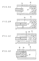
- Figures 2A to 2D are explanatory diagrams illustrating a process of removing fibrous foreign bodies out of a duct using the intraductal foreign body removal instrument 10.
- Figures 2A to 2D show sectional views of a duct 90 and the intraductal foreign body removal instrument 10 along the longitudinal axis. As shown in Figure 2A, first the free end side 10a of the intraductal foreign body removal instrument 10 is inserted through an opening of the duct 90 to or near a constriction caused by fibrous foreign bodies 80 in the duct 90.
- the guide tube 25 is inserted together, but made to wait a little behind the free end side 10a inserted to or near the constriction caused by the fibrous foreign bodies 80.
- the guide tube 25 is not shown in Figure 2A (the same is true in Figures 2B and 2C).
- the insertion of the free end side 10a into the duct 90 is conceptually indicated by an arrow near the free end side 10a.
- the insertion tube 20 tangled with the fibrous foreign bodies 80 and the wire 30 in the insertion tube 20 are stored once in the guide tube 25 together with the fibrous foreignbodies 80 before the entire intraductal foreign body removal instrument 10 is retrieved.
- the retrieval of the free end side 10a of the intraductal foreign body removal instrument 10 from the duct 90 is conceptually indicated by an arrow near the free end side 10a. In this way, the fibrous foreign bodies 80 can be removed from the duct 90.
- a catheter (intraductal foreign body removal instrument) is fed into the duct 90.
- the insertion tube 20 and the wire 30 in the insertion tube 20 have flexibility.
- the insertion tube 20 and the wire 30 in it can have small diameters. That is, the free end side 10a consists of only the insertion tube 20 (and the wire 30 in it) and does not have a special mechanism such as a gripping mechanism. This results in low resistance in the duct 90. Also, even elbows and similar bends do not offer high resistance. This in turn increases feed limits of the intraductal foreign body removal instrument 10 into the duct 90. Also, even if the duct 90 has a small diameter, the intraductal foreign body removal instrument 10 can be inserted easily into it. Thus, patient invasion can be reduced.
- the fibrous foreign bodies 80 After the fibrous foreign bodies 80 are tangled around the free end side 10a by the rotation of the wire 30 with the rotating device 40 as described above, they can be removed as the intraductal foreign body removal instrument 10 is retrieved from the duct 90 through the insertion position.
- the intraductal foreign body removal instrument 10 can be suitably used as a catheter to remove the fibrous foreign bodies 80 in the duct 90.
- the insertion tube 20 is loosely inserted into the guide tube 25. That is, the guide tube 25 and insertion tube 20 can move relative to each other in the longitudinal direction. Also, the insertion tube 20 is inserted into the guide tube 25 with a predetermined clearance which can accommodate fibrous foreign bodies 80 tangled around the free end side 10a. Consequently, the insertion tube 20 and the wire 30 in the insertion tube can be stored once in the guide tube 25 together with the foreign bodies 80 so that the free end side 10a is retrieved and foreign bodies are removed from the duct 90 through the insertion position. This suitably prevents the fibrous foreign bodies 80 from falling off the free end side as well as prevents them from damaging inner walls of the duct 90 during retrieval. Also, where the insertion tube 20 is covered by the guide tube 25, the vibration of the insertion tube 20 can be reduced by the guide tube 25.
- the intraductal foreign body removal instrument 10 can remove fibrous foreign bodies 80 (occluding objects such as thrombus) clogging constrictions in the duct 90, without damaging inner walls of the duct 90 using a simple mechanism which does not require a large, complex equipment configuration.
- the above-described intraductal foreign body removal instrument according to the present invention is not limited to the above embodiment and can be modified as required without departing from the spirit and scope of the present invention.
- the intraductal foreign body removal instrument according to the present invention is used as a catheter, the present invention is not limited to this and can also be used for other applications as long as it is used as an intraductal foreign body removal instrument to remove fibrous foreign bodies in ducts. For example, it canbe used to remove hairs (fibrous foreignbodies) clogging a drain pipe.
- the insertion tube 20 with the wire 30 in it is inserted into the guide tube 25, this is not restrictive and it is not strictly necessary to use the guide tube 25.
- the intraductal foreign body removal instrument is equipped with a guide tube to reduce vibration by means of the guide tube 25 in locations other than near the free end side 10a where convection caused by vibration is required, prevent the fibrous foreign bodies to be removed from falling off the free end side, and prevent the fibrous foreign bodies from damaging inner walls of the duct when they are retrieved.
- fluororesin PFA
- wire material of a nickel-titanium alloy is used for the wire 30 in the above embodiment, this is not restrictive and various materials are applicable as long as they are flexible.
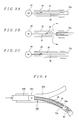
- the shapes of the insertion tube 20 and the wire 30 are not limited to those used in the above embodiment. For example, variations of the shapes of the insertion tube 20 and the wire 30 are shown in Figures 3A to 3C.
- the insertion tube 20 has a tubular shape with both longitudinal ends open, this is not restrictive and it may have a tubular shape with the free end side 10a closed as exemplified by a variation shown in Figure 3A.
- one or more holes may be made an appropriate distance away from the end on the free end side 10a of the insertion tube 20, thereby securing flow paths, as exemplified by a variation shown in Figure 3B.
- formation of the flow paths is conceptually indicated by arrows.
- the free end side 10a of the wire 30 is bent in a "dogleg shape" to form the bend 30a
- the bend is not limited to a dogleg shape and various shapes may be used.
- the wire 30 is made of a single filament of wire material, this is not restrictive and any wire will serve its purpose for the present invention as long as it can be rotated in the insertion tube.
- the intraductal foreign body removal instrument may employ a wire consisting of twisted filaments, or multiple untwisted filaments passed through the insertion tube 20 as the wire 30.
- the 0.5-mm diameter (outside diameter) insertion tube 20 and the 0.2-mm diameter wire 30 are used to reduce the diameter of the intraductal foreign body removal instrument 10, this is not restrictive and appropriate thickness may be selected depending on applications of the present invention.
- the rotating device 40 is placed outside the target duct and the insertion tube (together with the wire in it) is inserted into the duct
- the present invention is not limited to this.
- a microactuator insertable into a duct 90B in which an intraductal foreign body removal instrument 10B is used can be adopted as a rotating device 40B of the intraductal foreign body removal instrument 10B according to the present invention.
- One end of a flexible insertion tube 42B for pull-up is attached to the rotating device 40B.
- the other end of the flexible insertion tube 42B for pull-up is attached to a flexible-insertion-tube winder (not shown).
- the flexible insertion tube 42B is hollow and wiring or piping for use to drive the rotating device 40B is connected to the rotating device 40B, passing through the flexible insertion tube 42B.
- the configuration in Figure 4 is applicable, for example, when a duct has a relatively large opening and a large distance to a constriction with the bore of the duct getting narrower halfway. In such a case, if the free end side of the intraductal foreign body removal instrument is too long, the insertion tube and wire may get buckled and folded halfway through the duct, but the configuration in Figure 4 accommodates such a situation by making the free end side shorter.
- the intraductal foreign body removal instrument 10 although the axial lengths of the insertion tube 20 and wire 30 are shown in Figure 1 as being almost equal and the free end side 10a of the guide tube 25 is shown as being shorter than the insertion tube 20, this is not restrictive. These tubes and the like may have different lengths at least in the target duct as long as they serve their purpose for the present invention.
- the wire 30 alone may be increased in length on the side where the wire 30 is connected to the rotating device 40 while the guide tube 25 and insertion tube 20 have the same length.
- the intraductal foreign body removal instrument according to the present invention can have a large overall length because it allows a large amount of feed when feeding the free end side into the duct, but it can also be used for short-range applications.
- FIG. 5A is a schematic block diagram illustrating an overall experimental arrangement.
- a blood vessel model 50 was constructed of a glass tube to represent an intravital duct 90.
- the blood vessel model 50 could pump up water used to represent blood from a tank 70 and circulate it through the duct 90 using a circulation unit 60 equipped with a pump.
- a narrowed part 62 was provided to represent constriction caused by a thrombus by reducing the part of the glass tube in diameter.
- the center of a glass tube with an inside diameter D of 5.8 mm had its outside diameter d reduced to approximately 1 mm by heating with a burner.
- a thrombus (fibrous) formed of blood sampled from a rabbit was plugged into one end of the narrowed part 62 as fibrous foreign bodies 80.
- an elbow 64 was constituted of a pipe with multiple bends (two bends in the figure) and connected to one end of the narrowed part 62 to represent a blood vessel in a living body.
- a Y-shaped connecting pipe 66 was connected to the other end of the elbow 64, allowing a catheter (the intraductal foreign body removal instrument according to the above embodiment) to be inserted into one branch of the Y-shaped pipe (as indicated by arrow B in the figure).
- the wire 30 was rotated by the rotating device 40.
- the rotational speed of the rotating device 40 was ranged between 8,000 rpm and 18,000 rpm and an effect was observed in the entire range of rotational speed. It was found that as the rotational speed was increased, stronger convection (eddy) was produced, drawing the foreign bodies 80 more strongly to the free end side 10a. It was confirmed that after being tangled around the free end side 10a, the foreign bodies 80 could be removed by withdrawing the intraductal foreign body removal instrument 10 from the connecting pipe 66 serving as insertion position into the duct 90. Thus, it was confirmed that the intraductal foreign body removal instrument 10 according to the present invention could remove fibrous foreign bodies 80 out of the duct 90 without damaging inner walls of the duct 90 using a simple mechanism.
- the intraductal foreign body removal instrument according to the present invention can remove fibrous foreign bodies out of a duct without damaging inner walls of the duct using a simple mechanism.
Landscapes
- Health & Medical Sciences (AREA)
- Engineering & Computer Science (AREA)
- Surgery (AREA)
- Mechanical Engineering (AREA)
- Life Sciences & Earth Sciences (AREA)
- Biomedical Technology (AREA)
- Nuclear Medicine, Radiotherapy & Molecular Imaging (AREA)
- Vascular Medicine (AREA)
- Orthopedic Medicine & Surgery (AREA)
- Heart & Thoracic Surgery (AREA)
- Medical Informatics (AREA)
- Molecular Biology (AREA)
- Animal Behavior & Ethology (AREA)
- General Health & Medical Sciences (AREA)
- Public Health (AREA)
- Veterinary Medicine (AREA)
- Surgical Instruments (AREA)
- Cleaning In General (AREA)
Abstract
To provide an intraductal foreign body removal instrument which can remove fibrous foreign bodies 80 out of a duct 90 without damaging inner walls of the duct 90 using a simple mechanism. The instrument has a flexible insertion tube 20 inserted in the duct 90, a wire 30 made of flexible wire material and inserted in the insertion tube 20; and a rotating device 40 which rotates the wire 30 in the insertion tube 20. Furthermore, the instrument 10 has a flexible guide tube 25 which is inserted in the duct 90 and into which the insertion tube 20 is inserted loosely.
Description
- The present invention relates to an intraductal foreign body removal instrument used to remove fibrous foreign bodies out of ducts. More particularly, it relates to an intraductal foreign body removal instrument which can be suitably used as a catheter to remove fibrous occluding objects and the like out of intravital ducts such as blood vessels.
- Conventionally, intraductal foreign body removal instruments have been developed to remove fibrous foreign bodies clogging constrictions and the like in ducts through which a fluid passes.
A technique described in JP10-175705A discloses an intraductal foreign body removal instrument, comprising a gripping mechanism which is attached to a main unit (foreign body removal instrument) to grip, for example, foreign bodies in a duct using claws, wherein a tip of a pull-up wire is attached to the main unit, and the other end of the wire is attached to a wire winder installed outside the duct.
According to this technique, the main unit is fed into a duct until it gets close to a constriction caused by foreign bodies. Then the gripping mechanism is brought close to the foreign bodies and the claws are closed to grip the foreign bodies. Then the pull-up wire is wound by the winder, taking the main unit out of the duct, and thereby removing the foreign bodies. - However, an intraductal foreign body removal instrument comprising a gripping mechanism, as is the case with the technique disclosed in JP10-175705A, involves feeding the gripping mechanism itself composed of a large number of parts into a duct, which increases resistance in the duct. Consequently, for example, elbows or similar bends increase resistance, causing a problem of limited feed. Also, to position the gripping mechanism in the duct and remove (grip) foreign bodies, it is necessary to control relative distance from the foreign bodies by subtly adjusting an actuator. This presents a problem of increased time required to remove the foreign bodies.
- Furthermore, under circumstances where a duct has a small diameter allowing a limited work area, limited space may be available for use to open and close the gripping mechanism. Also, there may be cases in which the gripping mechanism itself cannot be fed to a constriction in the duct due to its size.
Possible circumstances where a duct has a small diameter allowing a limited work area include an intravital duct from which foreign bodies are removed. When removing foreign bodies out of an intravital duct, which is small in diameter and twists turns intricately, without damaging body tissues, the above problems become more prominent.
A catheter, for example, is used to remove foreign bodies out of intravital ducts. Although various catheters have been developed in pursuit of less invasive therapies for various diseases, they leave room for further studies. - For example, when removing a fibrous thrombus from a constricted blood vessel, there is a problem in that after a balloon catheter for percutaneous transluminal coronary angioplasty and the like is used mainly to dilate the constricted blood vessel, a retrieval catheter must be inserted separately to retrieve (remove) fine fragments of the thrombus produced when the constriction is dilated by the balloon.
The present invention has been made in view of the above problems and has an object to provide an intraductal foreign body removal instrument which can remove fibrous foreign bodies clogging elbows, narrowed parts, or other constrictions of pipes or similar ducts without requiring a large, complex equipment configuration. More particularly, it has an object to provide an intraductal foreignbody removal instrument which can be suitably used as a catheter to be inserted in intravital ducts such as blood vessels to remove fibrous occluding obj ects out of the duct. - To achieve the above object, the present invention as set forth in claim 1 provides an intraductal foreign body removal instrument which removes fibrous foreign bodies out of a duct, characterized by comprising: a flexible insertion tube inserted in the duct; a wire made of flexible wire material and inserted in the insertion tube; and a rotating device which rotates the wire in the insertion tube.
The invention set forth in claim 1 allows the insertion tube and the wire in the insertion tube to be reduced in diameter, making it possible to insert them easily in a duct. Besides, that side (hereinafter referred to as a free end side) of the intraductal foreign body removal instrument which is inserted in a duct is not equipped with any special mechanism (such as the gripping mechanism of the conventional example). That is, when removing fibrous foreign bodies out of a duct using the intraductal foreign body removal instrument, the free end side is fed into the duct, but it does not encounter much resistance because it is only the insertion tube (and the wire in the insertion tube). Consequently, even elbows and similar bends, for example, do not offer high resistance. Thus, the instrument can be used even in small-diameter ducts. Also, feed limits of the intraductal foreign body removal instrument can be increased. - When the free end side of the intraductal foreign body removal instrument is inserted to a desired position, fibrous foreign bodies can be tangled around the free end side of the intraductal foreign body removal instrument by rotating the wire by the rotating device. After the fibrous foreign bodies are tangled, they can be removed as the intraductal foreign body removal instrument is retrieved from the duct through insertion position.
The mechanism by which fibrous foreign bodies can be tangled around the free end side of the intraductal foreign body removal instrument through rotation of the wire is not completely clear, but is presumed to be as follows. - When the wire rotates, its whirling causes the insertion tube to vibrate. The vibration lowers static pressure near the free end side of the intraductal foreign body removal instrument. Consequently, fluid convection(eddy) toward the intraductal foreign body removal instrument occurs in the duct. The vibration and convection produce a force which moves the fibrous foreign bodies toward the free end side of the intraductal foreign body removal instrument, causing them to get tangled around the free end side.
In this way, the intraductal foreign body removal instrument according to the present invention can remove fibrous foreign bodies clogging elbows, narrowed parts, or other constrictions of pipes or similar ducts without requiring a large, complex equipment configuration.
Claim 2 of the present invention sets forth the intraductal foreign body removal instrument according to claim 1, characterized in that the intraductal foreign body removal instrument is a catheter inserted into an intravital duct. - The invention set forth in claim 2 allows a small-diameter catheter with a simple mechanism to be constructed, making it possible to remove fibrous foreign bodies out of intravital ducts without damaging inner walls of the ducts. Thus, the intraductal foreign body removal instrument is less invasive to the patients.
Claim 3 of the present invention sets forth the intraductal foreign body removal instrument according to claim 1 or 2, characterizedby further comprising a flexible guide tube which is inserted in the duct and into which the insertion tube is inserted loosely. - The invention set forth in claim 3, according to which the insertion tube is loosely inserted into the guide tube, allows the guide tube and insertion tube to move relative to each other in the longitudinal direction. If the clearance between the guide tube and insertion tube is designed to accommodate fibrous foreign bodies tangled around the free end side of the insertion tube, when withdrawing the intraductal foreign body removal instrument from the duct through insertion position, the wire inside insertion tube and insertion tube can be retrieved together with the fibrous foreign bodies after being stored in the guide tube. This suitably prevents the fibrous foreign bodies from falling off the free end side of the insertion tube as well as prevents them from damaging inner walls of the duct during retrieval. Also, where the insertion tube is covered by the guide tube, the vibration of the insertion tube can be reduced by the guide tube.
-
- Figure 1 is a schematic block diagram showing an embodiment of an intraductal foreign body removal instrument according to the present invention;
- Figures 2A to 2D are explanatory diagrams illustrating a process of removing fibrous foreign bodies out of a duct using the intraductal foreign body removal instrument according to the present invention;
- Figures 3A to 3C are explanatory diagrams illustrating a variation of the intraductal foreign body removal instrument according to the present invention;
- Figure 4 is an explanatory diagram illustrating a variation of the intraductal foreign body removal instrument according to the present invention; and
- Figures 5A and 5B are explanatory diagrams illustrating an example of (experiment with) the intraductal foreign body removal instrument according to the present invention, where Figure 5A is a schematic block diagram showing an overall view of an experimental arrangement and Figure 5B is an enlarged view of part A in Figure 5A.
-
- 10
- Intraductal foreign body removal instrument
- 20
- Insertion tube
- 25
- Guide tube
- 30
- Wire
- 40
- Rotating device
- 50
- Blood vessel model (experimental arrangement)
- 60
- Circulation unit
- 62
- Narrowed part
- 64
- Elbow
- 66
- Connecting pipe
- 70
- Tank
- 80
- (Fibrous) foreign bodies
- 90
- Duct
- An embodiment of an intraductal foreign body removal instrument according to the present invention will be described below by referring to drawings as required.
In this embodiment, the intraductal foreign body removal instrument according to the present invention is configured to be suitably used as a catheter inserted in an intravital duct to remove fibrous occluding objects out of the duct under circumstances, such as in a living body, where the duct is narrow and tortuous allowing a limited work area. Incidentally, examples of fibrous occluding objects in intravital ducts include thrombus produced in blood vessels. - Figure 1 is a schematic block diagram of the intraductal foreign
body removal instrument 10 according to the present invention. Incidentally, the figure shows a sectional view of an insertion tube and guide tube along the longitudinal axis.
As shown in the figure, the intraductal foreignbody removal instrument 10 comprises aflexible insertion tube 20 inserted in a duct, awire 30 made of flexible wire material and passed through theinsertion tube 20, and arotating device 40 which rotates thewire 30 in theinsertion tube 20. - Furthermore, the intraductal foreign
body removal instrument 10 comprises aguide tube 25 inserted into the duct together with theinsertion tube 20 containing thewire 30. Thus, theinsertion tube 20 containing thewire 30 is passed through theguide tube 25.
Specifically, theinsertion tube 20 consists of annular cross sections extending continuously in the longitudinal direction and is open at both ends. It is a thin-walled, 0.5-mm diameter (outside diameter) tube formed of highly transparent fluororesin (PFA) with excellent heat and chemical resistance. - The
wire 30 is made of wire material of a nickel-titanium alloy and is 0.2 mm in diameter. As shown in Figure 1, a roughlydogleg bend 30a is formed on that side (hereinafter referred to as a free end side) 10a of thewire 30 which is inserted into the target duct as the intraductal foreignbody removal instrument 10 is inserted.
Any actuator which can output a rotary motion can be suitably used as therotating device 40. According to this embodiment, thatend 30b of thewire 30 which is opposite to thebend 30a is connected to an output shaft of therotating device 40 via a connection joint (not shown). Consequently therotating device 40 can rotate thewire 30 in theinsertion tube 20. - As in the case of the
insertion tube 20, theguide tube 25 consists of annular cross sections extending continuously in the longitudinal direction and is open at both ends. It is a thin-walled tube formed of highly transparent fluororesin (PFA) with excellent heat and chemical resistance. The inside diameter of theguide tube 25 is larger than the outside diameter of theinsertion tube 20 so that theinsertion tube 20 can be inserted loosely into theguide tube 25 with a predetermined clearance.
Next, description will be given of how to use the intraductal foreignbody removal instrument 10 configured as described above as well as its operation and effect. - Figures 2A to 2D are explanatory diagrams illustrating a process of removing fibrous foreign bodies out of a duct using the intraductal foreign
body removal instrument 10. Figures 2A to 2D show sectional views of aduct 90 and the intraductal foreignbody removal instrument 10 along the longitudinal axis.
As shown in Figure 2A, first thefree end side 10a of the intraductal foreignbody removal instrument 10 is inserted through an opening of theduct 90 to or near a constriction caused by fibrousforeign bodies 80 in theduct 90. - At this time, the
guide tube 25 is inserted together, but made to wait a little behind thefree end side 10a inserted to or near the constriction caused by the fibrousforeign bodies 80. Thus, theguide tube 25 is not shown in Figure 2A (the same is true in Figures 2B and 2C). Incidentally, in Figure 2A, the insertion of thefree end side 10a into theduct 90 is conceptually indicated by an arrow near thefree end side 10a.
Next, as shown in Figure 2B, when thefree end side 10a of the intraductal foreignbody removal instrument 10 is inserted to a predetermined position (near the constriction in the figure) in theduct 90, thewire 30 is rotated in theinsertion tube 20 by the rotating device 40 (not shown in Figures 2A to 2D) . Incidentally, the rotation of thewire 30 in theinsertion tube 20 is conceptually indicated by an arrow around the wire 30 (the same is true hereinafter). - As shown in Figure 2C, when the
wire 30 rotates in theinsertion tube 20, its whirling causes theinsertion tube 20 to vibrate. Consequently, the fibrousforeign bodies 80 are drawn to thefree end side 10a from the constriction. Here, only thewire 30 is rotated directly by driving force of therotating device 40, and theinsertion tube 20 around thewire 30 is not rotated directly by the driving force of therotating device 40. Consequently, inner walls of theintravital duct 90 are hardly damaged. Incidentally, vibration of theinsertion tube 20 caused by the whirling of thewire 30 rotating in theinsertion tube 20 is conceptually indicated by wavy lines near the insertion tube 20 (the same is true hereinafter) . - Presumably, this phenomenon is explained as follows. The vibration of the
insertion tube 20 lowers static pressure around the intraductal foreignbody removal instrument 10. Consequently, fluid convection (eddy) toward the intraductal foreignbody removal instrument 10 occurs in theduct 90. The vibration and convection produce a force which moves the fibrousforeign bodies 80 toward thefree end side 10a of the intraductal foreignbody removal instrument 10.
Then, as shown in Figure 2D, the fibrousforeign bodies 80 drawn to thefree end side 10a get tangled around it. After the fibrousforeign bodies 80 are tangled, the intraductal foreignbody removal instrument 10 is retrieved from theduct 90 through insertion position. - In so doing, as shown in Figure 2D, the
insertion tube 20 tangled with the fibrousforeign bodies 80 and thewire 30 in theinsertion tube 20 are stored once in theguide tube 25 together with thefibrous foreignbodies 80 before the entire intraductal foreignbody removal instrument 10 is retrieved. This prevents the fibrousforeign bodies 80 from falling off the free end side as well as prevents them from damaging inner walls of theduct 90 when the intraductal foreignbody removal instrument 10 is retrieved. Incidentally, in the figure, the retrieval of thefree end side 10a of the intraductal foreignbody removal instrument 10 from theduct 90 is conceptually indicated by an arrow near thefree end side 10a. In this way, the fibrousforeign bodies 80 can be removed from theduct 90. - Thus, in the operation of removing the fibrous
foreign bodies 80 out of theintravital duct 90, a catheter (intraductal foreign body removal instrument) is fed into theduct 90. With the intraductal foreignbody removal instrument 10 according to the present invention, theinsertion tube 20 and thewire 30 in theinsertion tube 20 have flexibility. Besides, theinsertion tube 20 and thewire 30 in it can have small diameters. That is, thefree end side 10a consists of only the insertion tube 20 (and thewire 30 in it) and does not have a special mechanism such as a gripping mechanism. This results in low resistance in theduct 90. Also, even elbows and similar bends do not offer high resistance. This in turn increases feed limits of the intraductal foreignbody removal instrument 10 into theduct 90. Also, even if theduct 90 has a small diameter, the intraductal foreignbody removal instrument 10 can be inserted easily into it. Thus, patient invasion can be reduced. - After the fibrous
foreign bodies 80 are tangled around thefree end side 10a by the rotation of thewire 30 with therotating device 40 as described above, they can be removed as the intraductal foreignbody removal instrument 10 is retrieved from theduct 90 through the insertion position. Thus, even under circumstances where theduct 90 is narrow and tortuous allowing a limited work area, the intraductal foreignbody removal instrument 10 can be suitably used as a catheter to remove the fibrousforeign bodies 80 in theduct 90. - Furthermore, the
insertion tube 20 is loosely inserted into theguide tube 25. That is, theguide tube 25 andinsertion tube 20 can move relative to each other in the longitudinal direction. Also, theinsertion tube 20 is inserted into theguide tube 25 with a predetermined clearance which can accommodate fibrousforeign bodies 80 tangled around thefree end side 10a. Consequently, theinsertion tube 20 and thewire 30 in the insertion tube can be stored once in theguide tube 25 together with theforeign bodies 80 so that thefree end side 10a is retrieved and foreign bodies are removed from theduct 90 through the insertion position. This suitably prevents the fibrousforeign bodies 80 from falling off the free end side as well as prevents them from damaging inner walls of theduct 90 during retrieval. Also, where theinsertion tube 20 is covered by theguide tube 25, the vibration of theinsertion tube 20 can be reduced by theguide tube 25. - Thus, the intraductal foreign
body removal instrument 10 can remove fibrous foreign bodies 80 (occluding objects such as thrombus) clogging constrictions in theduct 90, without damaging inner walls of theduct 90 using a simple mechanism which does not require a large, complex equipment configuration.
Incidentally, the above-described intraductal foreign body removal instrument according to the present invention is not limited to the above embodiment and can be modified as required without departing from the spirit and scope of the present invention.
For example, although in the above embodiment, the intraductal foreign body removal instrument according to the present invention is used as a catheter, the present invention is not limited to this and can also be used for other applications as long as it is used as an intraductal foreign body removal instrument to remove fibrous foreign bodies in ducts. For example, it canbe used to remove hairs (fibrous foreignbodies) clogging a drain pipe. - Also, although in the above embodiment, the
insertion tube 20 with thewire 30 in it is inserted into theguide tube 25, this is not restrictive and it is not strictly necessary to use theguide tube 25. However, preferably the intraductal foreign body removal instrument is equipped with a guide tube to reduce vibration by means of theguide tube 25 in locations other than near thefree end side 10a where convection caused by vibration is required, prevent the fibrous foreign bodies to be removed from falling off the free end side, and prevent the fibrous foreign bodies from damaging inner walls of the duct when they are retrieved. - Also, although in the above embodiment, fluororesin (PFA) is used for the
insertion tube 20 and guidetube 25, this is not restrictive and various materials are applicable as long as they are flexible. Also, although wire material of a nickel-titanium alloy is used for thewire 30 in the above embodiment, this is not restrictive and various materials are applicable as long as they are flexible.
Also, the shapes of theinsertion tube 20 and thewire 30 are not limited to those used in the above embodiment. For example, variations of the shapes of theinsertion tube 20 and thewire 30 are shown in Figures 3A to 3C. - For example, although in the above embodiment, the
insertion tube 20 has a tubular shape with both longitudinal ends open, this is not restrictive and it may have a tubular shape with thefree end side 10a closed as exemplified by a variation shown in Figure 3A. However, to produce convection to thefree end side 10a efficiently, it is desirable to open up thefree end side 10a of theinsertion tube 20. Incidentally, to produce such convection more efficiently, one or more holes may be made an appropriate distance away from the end on thefree end side 10a of theinsertion tube 20, thereby securing flow paths, as exemplified by a variation shown in Figure 3B. Incidentally, in Figure 3B, formation of the flow paths is conceptually indicated by arrows. - Also, although in the above embodiment, for example, the
free end side 10a of thewire 30 is bent in a "dogleg shape" to form thebend 30a, this is not restrictive and thefree end side 10a may be straight as exemplified by a variation shown in Figure 3C instead of being bent. However, to produce convection to thefree end side 10a efficiently, it is desirable to form a bend on thefree end side 10a of thewire 30 as in the case of the above embodiment. Incidentally, the bend is not limited to a dogleg shape and various shapes may be used. - Also, although in the above embodiment, the
wire 30 is made of a single filament of wire material, this is not restrictive and any wire will serve its purpose for the present invention as long as it can be rotated in the insertion tube. For example, the intraductal foreign body removal instrument may employ a wire consisting of twisted filaments, or multiple untwisted filaments passed through theinsertion tube 20 as thewire 30.
Also, although in the above embodiment, the 0.5-mm diameter (outside diameter)insertion tube 20 and the 0.2-mm diameter wire 30 are used to reduce the diameter of the intraductal foreignbody removal instrument 10, this is not restrictive and appropriate thickness may be selected depending on applications of the present invention. - Also, although in the above embodiment of the intraductal foreign body removal instrument according to the present invention, the rotating
device 40 is placed outside the target duct and the insertion tube (together with the wire in it) is inserted into the duct, the present invention is not limited to this.
For example, as exemplified by a variation shown in Figure 4, a microactuator insertable into aduct 90B in which an intraductal foreignbody removal instrument 10B is used can be adopted as arotating device 40B of the intraductal foreignbody removal instrument 10B according to the present invention. One end of aflexible insertion tube 42B for pull-up is attached to therotating device 40B. The other end of theflexible insertion tube 42B for pull-up is attached to a flexible-insertion-tube winder (not shown). Theflexible insertion tube 42B is hollow and wiring or piping for use to drive therotating device 40B is connected to therotating device 40B, passing through theflexible insertion tube 42B. - According to this variation, the intraductal foreign
body removal instrument 10B itself is inserted into theduct 90B until it gets close to a constriction constricted by fibrousforeign bodies 80 in theduct 90B. Then, thefree end side 10a of the intraductal foreignbody removal instrument 10B is brought close to the fibrousforeign bodies 80, which then get tangled around theinsertion tube 20 as thewire 30 is rotated by therotating device 40B. Then, as theflexible insertion tube 42B is wound by the flexible-insertion-tube winder, the intraductal foreignbody removal instrument 10B is retrieved from theduct 90B to remove the fibrousforeign bodies 80. Incidentally, although noguide tube 25 is used in this variation, the intraductal foreignbody removal instrument 10B can be configured with aguide tube 25. - The configuration in Figure 4 is applicable, for example, when a duct has a relatively large opening and a large distance to a constriction with the bore of the duct getting narrower halfway. In such a case, if the free end side of the intraductal foreign body removal instrument is too long, the insertion tube and wire may get buckled and folded halfway through the duct, but the configuration in Figure 4 accommodates such a situation by making the free end side shorter.
- In the intraductal foreign
body removal instrument 10 according to the present invention, although the axial lengths of theinsertion tube 20 andwire 30 are shown in Figure 1 as being almost equal and thefree end side 10a of theguide tube 25 is shown as being shorter than theinsertion tube 20, this is not restrictive. These tubes and the like may have different lengths at least in the target duct as long as they serve their purpose for the present invention. For example, thewire 30 alone may be increased in length on the side where thewire 30 is connected to therotating device 40 while theguide tube 25 andinsertion tube 20 have the same length. Also, the intraductal foreign body removal instrument according to the present invention can have a large overall length because it allows a large amount of feed when feeding the free end side into the duct, but it can also be used for short-range applications. - Next, description will be given of an example (experiment) in which the intraductal foreign body removal instrument according to the present invention is used.
This example is a basic experiment conducted to check operation and effect of the intraductal foreign body removal instrument with the configuration of the above embodiment when it is used as a catheter inserted into an intravital duct. Incidentally, the intraductal foreign body removal instrument used in this experiment was the same as the intraductal foreignbody removal instrument 10 described above except that it was not equipped with theguide tube 25, and thus detailed description thereof will be omitted.
Figure 5A is a schematic block diagram illustrating an overall experimental arrangement.
As shown in the figure, ablood vessel model 50 was constructed of a glass tube to represent anintravital duct 90. Theblood vessel model 50 could pump up water used to represent blood from atank 70 and circulate it through theduct 90 using acirculation unit 60 equipped with a pump. - Specifically, as illustrated by the enlarged view of part A shown in Figure 5B, a
narrowed part 62 was provided to represent constriction caused by a thrombus by reducing the part of the glass tube in diameter. To produce thenarrowed part 62, the center of a glass tube with an inside diameter D of 5.8 mm had its outside diameter d reduced to approximately 1 mm by heating with a burner. Then, a thrombus (fibrous) formed of blood sampled from a rabbit was plugged into one end of the narrowedpart 62 as fibrousforeign bodies 80.
As shown in Figure 5A, anelbow 64 was constituted of a pipe with multiple bends (two bends in the figure) and connected to one end of the narrowedpart 62 to represent a blood vessel in a living body. A Y-shaped connectingpipe 66 was connected to the other end of theelbow 64, allowing a catheter (the intraductal foreign body removal instrument according to the above embodiment) to be inserted into one branch of the Y-shaped pipe (as indicated by arrow B in the figure). - An experiment to remove the fibrous
foreign bodies 80 clogging thenarrowed part 62 was conducted using the intraductal foreignbody removal instrument 10 on theblood vessel model 50 configured as described above.
First, the catheter (the intraductal foreign body removal instrument 10) was inserted in one branch of the Y-shaped connectingpipe 66 and passed through the multiple bends in theelbow 64. Since the 0.5-mm diameter (outside diameter)insertion tube 20 and 0.2-mm diameter wire 30 were used to reduce the diameter of the catheter (the intraductal foreign body removal instrument 10) as described in the above embodiment, the catheter could be fed easily to near one end of the narrowed part 62 (at the left of theforeign bodies 80 in Figure 5B). - Next, the
wire 30 was rotated by the rotatingdevice 40. As a result, it was observed that theforeign bodies 80 were drawn to thefree end side 10a of the intraductal foreignbody removal instrument 10 and tangled around it as described in the above embodiment. The rotational speed of therotating device 40 was ranged between 8,000 rpm and 18,000 rpm and an effect was observed in the entire range of rotational speed. It was found that as the rotational speed was increased, stronger convection (eddy) was produced, drawing theforeign bodies 80 more strongly to thefree end side 10a.
It was confirmed that after being tangled around thefree end side 10a, theforeign bodies 80 could be removed by withdrawing the intraductal foreignbody removal instrument 10 from the connectingpipe 66 serving as insertion position into theduct 90.
Thus, it was confirmed that the intraductal foreignbody removal instrument 10 according to the present invention could remove fibrousforeign bodies 80 out of theduct 90 without damaging inner walls of theduct 90 using a simple mechanism. - The intraductal foreign body removal instrument according to the present invention can remove fibrous foreign bodies out of a duct without damaging inner walls of the duct using a simple mechanism.
Claims (3)
- An intraductal foreign body removal instrument which removes fibrous foreign bodies out of a duct, characterized by comprising:a flexible insertion tube inserted in the duct; a wire made of flexible wire material and inserted in the insertion tube; and a rotating device which rotates the wire in the insertion tube.
- The intraductal foreign body removal instrument according to claim 1, characterized in that the intraductal foreign body removal instrument is a catheter inserted into an intravital duct.
- The intraductal foreign body removal instrument according to claim 1 or 2, characterized by further comprising a flexible guide tube which is inserted in the duct and into which the insertion tube is inserted loosely.
Applications Claiming Priority (2)
| Application Number | Priority Date | Filing Date | Title |
|---|---|---|---|
| JP2003335749A JP2005095839A (en) | 2003-09-26 | 2003-09-26 | Foreign matter removal instrument in pipeline |
| PCT/JP2004/014085 WO2005030408A1 (en) | 2003-09-26 | 2004-09-27 | Tool for removing foreign object in pipe line |
Publications (1)
| Publication Number | Publication Date |
|---|---|
| EP1666168A1 true EP1666168A1 (en) | 2006-06-07 |
Family
ID=34386074
Family Applications (1)
| Application Number | Title | Priority Date | Filing Date |
|---|---|---|---|
| EP04788181A Withdrawn EP1666168A1 (en) | 2003-09-26 | 2004-09-27 | Tool for removing foreign object in pipe line |
Country Status (5)
| Country | Link |
|---|---|
| US (1) | US20060276814A1 (en) |
| EP (1) | EP1666168A1 (en) |
| JP (1) | JP2005095839A (en) |
| CN (1) | CN1816400A (en) |
| WO (1) | WO2005030408A1 (en) |
Cited By (7)
| Publication number | Priority date | Publication date | Assignee | Title |
|---|---|---|---|---|
| WO2012078177A1 (en) * | 2010-12-09 | 2012-06-14 | Actuated Medical, Inc. | Devices for clearing blockages in in-situ artificial lumens |
| US9308348B2 (en) | 2007-11-21 | 2016-04-12 | Actuated Medical, Inc. | Devices and methods for clearing occlusions and for providing irrigation in in-situ artificial and natural lumens |
| US9352122B2 (en) | 2007-11-21 | 2016-05-31 | Actuated Medical, Inc. | Devices for clearing blockages in small bore in-situ artificial lumens |
| US9561337B2 (en) | 2012-10-11 | 2017-02-07 | Actuated Medical, Inc. | Active system for in-situ clearing of secretions and occlusions in tubes |
| US10307340B2 (en) | 2007-11-21 | 2019-06-04 | Actuated Medical, Inc. | Devices for clearing blockages in artificial and natural lumens |
| US10342902B2 (en) | 2015-10-19 | 2019-07-09 | Actuated Medical, Inc. | Device for in situ clearing of occlusions in tubing |
| US11147944B2 (en) | 2015-10-19 | 2021-10-19 | Actuated Medical, Inc. | Handset for occlusion clearing device |
Families Citing this family (16)
| Publication number | Priority date | Publication date | Assignee | Title |
|---|---|---|---|---|
| JP2008086900A (en) * | 2006-09-30 | 2008-04-17 | Nidec Sankyo Corp | Cleaner |
| US9795406B2 (en) | 2010-05-13 | 2017-10-24 | Rex Medical, L.P. | Rotational thrombectomy wire |
| US9023070B2 (en) | 2010-05-13 | 2015-05-05 | Rex Medical, L.P. | Rotational thrombectomy wire coupler |
| US8663259B2 (en) | 2010-05-13 | 2014-03-04 | Rex Medical L.P. | Rotational thrombectomy wire |
| US8764779B2 (en) | 2010-05-13 | 2014-07-01 | Rex Medical, L.P. | Rotational thrombectomy wire |
| CN113786548B (en) | 2014-02-17 | 2024-04-12 | 科里福罗公司 | Medical Tube Cleaning Equipment |
| US10974023B2 (en) | 2014-02-17 | 2021-04-13 | Clearflow, Inc. | Medical tube clearance |
| US9743943B2 (en) * | 2015-03-31 | 2017-08-29 | Terumo Kabushiki Kaisha | Method for removing calculus from an access sheath |
| WO2019222117A1 (en) * | 2018-05-14 | 2019-11-21 | Stryker Corporation | Inverting thrombectomy apparatuses and methods of use |
| AU2020206041A1 (en) * | 2019-01-11 | 2021-07-29 | Clearflow, Inc. | Medical tube clearance device |
| CN110193503B (en) * | 2019-06-03 | 2020-11-06 | 常州市第二人民医院 | side port branch artificial blood vessel |
| US11925745B1 (en) * | 2019-11-27 | 2024-03-12 | Clearflow, Inc. | Clearance system for medical tubes such as surgical drains |
| JP2024524693A (en) * | 2021-07-15 | 2024-07-05 | バード・アクセス・システムズ,インコーポレーテッド | Systems for targeted thrombolytic drug delivery - Patents.com |
| WO2023010066A1 (en) * | 2021-07-28 | 2023-02-02 | SonDance Solutions LLC | Methods and systems to remove obstructions in a conveyance pipe |
| NL2032146B9 (en) * | 2022-06-13 | 2024-01-15 | Nmgn Medical | Endoscopic tool |
| US20260083116A1 (en) * | 2024-09-25 | 2026-03-26 | Brian Jarvis | Poison depositing apparatus for reaching into gopher holes |
Family Cites Families (17)
| Publication number | Priority date | Publication date | Assignee | Title |
|---|---|---|---|---|
| US6106538A (en) * | 1984-05-14 | 2000-08-22 | Shiber; Samuel | Method for forming an internal coronary bypass |
| CA1266597C (en) * | 1984-09-10 | 1990-03-13 | Transluminal thrombectomy apparatus | |
| US4646736A (en) * | 1984-09-10 | 1987-03-03 | E. R. Squibb & Sons, Inc. | Transluminal thrombectomy apparatus |
| US5116350B1 (en) * | 1987-03-17 | 1997-06-17 | Cordis Corp | Catheter system having distal tip for opening obstructions |
| JPH0380872A (en) * | 1989-05-12 | 1991-04-05 | Samuel Shiber | Atelectomy apparatus |
| JP2548859Y2 (en) * | 1992-07-28 | 1997-09-24 | 三菱重工業株式会社 | Internal cleaning tool for small diameter pipes |
| JPH07124247A (en) * | 1993-11-04 | 1995-05-16 | Buaayu:Kk | Foreign object suction catheter |
| US5868754A (en) * | 1996-06-12 | 1999-02-09 | Target Therapeutics, Inc. | Medical retrieval device |
| US5785689A (en) * | 1996-07-18 | 1998-07-28 | Act Medical, Inc. | Endoscopic catheter sheath position control |
| US5908395A (en) * | 1997-03-17 | 1999-06-01 | Advanced Cardiovascular Systems, Inc. | Vibrating guidewire |
| US6824550B1 (en) * | 2000-04-06 | 2004-11-30 | Norbon Medical, Inc. | Guidewire for crossing occlusions or stenosis |
| JP2000126303A (en) * | 1998-10-26 | 2000-05-09 | Asahi Intecc Co Ltd | Multifunctional wire for vascular treatment |
| ATE424773T1 (en) * | 1999-02-02 | 2009-03-15 | Samuel Shiber | SYSTEM FOR A FLEXIBLE AGITATOR |
| US6143009A (en) * | 1999-02-02 | 2000-11-07 | Shiber; Samuel | Flexible-agitator system and method |
| US6702830B1 (en) * | 1999-09-17 | 2004-03-09 | Bacchus Vascular, Inc. | Mechanical pump for removal of fragmented matter and methods of manufacture and use |
| US6454775B1 (en) * | 1999-12-06 | 2002-09-24 | Bacchus Vascular Inc. | Systems and methods for clot disruption and retrieval |
| JP2002346496A (en) * | 2001-05-24 | 2002-12-03 | Mitsubishi Heavy Ind Ltd | Apparatus and method for removing foreign matter |
-
2003
- 2003-09-26 JP JP2003335749A patent/JP2005095839A/en active Pending
-
2004
- 2004-09-27 WO PCT/JP2004/014085 patent/WO2005030408A1/en not_active Ceased
- 2004-09-27 US US10/559,759 patent/US20060276814A1/en not_active Abandoned
- 2004-09-27 CN CN200480018772.2A patent/CN1816400A/en active Pending
- 2004-09-27 EP EP04788181A patent/EP1666168A1/en not_active Withdrawn
Non-Patent Citations (1)
| Title |
|---|
| See references of WO2005030408A1 * |
Cited By (15)
| Publication number | Priority date | Publication date | Assignee | Title |
|---|---|---|---|---|
| US9011606B2 (en) | 2007-11-21 | 2015-04-21 | Actuated Medical, Inc. | Method for clearing blockages in in-situ artificial lumens |
| US9101700B2 (en) | 2007-11-21 | 2015-08-11 | Actuated Medical, Inc. | Devices for clearing blockages in in-situ artificial lumens |
| US8574377B2 (en) | 2007-11-21 | 2013-11-05 | Actuated Medical, Inc. | Devices for clearing blockages in in-situ artificial lumens |
| US8603254B2 (en) | 2007-11-21 | 2013-12-10 | Actuated Medical, Inc. | Methods for clearing blockages in in-situ artificial lumens |
| US8690861B2 (en) | 2007-11-21 | 2014-04-08 | Actuated Medical, Inc. | Devices for clearing blockages in in-situ artificial lumens |
| US8906169B2 (en) | 2007-11-21 | 2014-12-09 | Actuated Medical, Inc. | Devices for clearing blockages in in-situ artificial lumens |
| US8262645B2 (en) | 2007-11-21 | 2012-09-11 | Actuated Medical, Inc. | Devices for clearing blockages in in-situ artificial lumens |
| US11890259B2 (en) | 2007-11-21 | 2024-02-06 | Actuated Medical, Inc. | Devices for clearing blockages in artificial and natural lumens |
| US10307340B2 (en) | 2007-11-21 | 2019-06-04 | Actuated Medical, Inc. | Devices for clearing blockages in artificial and natural lumens |
| US9352122B2 (en) | 2007-11-21 | 2016-05-31 | Actuated Medical, Inc. | Devices for clearing blockages in small bore in-situ artificial lumens |
| US9308348B2 (en) | 2007-11-21 | 2016-04-12 | Actuated Medical, Inc. | Devices and methods for clearing occlusions and for providing irrigation in in-situ artificial and natural lumens |
| WO2012078177A1 (en) * | 2010-12-09 | 2012-06-14 | Actuated Medical, Inc. | Devices for clearing blockages in in-situ artificial lumens |
| US9561337B2 (en) | 2012-10-11 | 2017-02-07 | Actuated Medical, Inc. | Active system for in-situ clearing of secretions and occlusions in tubes |
| US10342902B2 (en) | 2015-10-19 | 2019-07-09 | Actuated Medical, Inc. | Device for in situ clearing of occlusions in tubing |
| US11147944B2 (en) | 2015-10-19 | 2021-10-19 | Actuated Medical, Inc. | Handset for occlusion clearing device |
Also Published As
| Publication number | Publication date |
|---|---|
| WO2005030408A1 (en) | 2005-04-07 |
| JP2005095839A (en) | 2005-04-14 |
| CN1816400A (en) | 2006-08-09 |
| US20060276814A1 (en) | 2006-12-07 |
Similar Documents
| Publication | Publication Date | Title |
|---|---|---|
| US20060276814A1 (en) | Tool for removing foreign object in pipe line | |
| US5653696A (en) | Stent unclogging method | |
| CN102844071B (en) | Low profile guiding catheter for neurovascular applications | |
| US4857046A (en) | Drive catheter having helical pump drive shaft | |
| JP5694917B2 (en) | Catheter cleaning mandrel | |
| US6156046A (en) | Methods and systems for treating obstructions in a body lumen | |
| CN100469398C (en) | Guiding wire | |
| CN101448542A (en) | Catheter insertion sheath with adjustable flexibility | |
| JP2003534057A (en) | Multi-lumen biliary catheter with oblique guidewire exit | |
| AU2002354761A1 (en) | Torqueable soft tip medical device and method of usage | |
| WO2003004086A2 (en) | Troqueable soft tip medical device and method of usage | |
| JP2004024625A (en) | Catheter and medical tube | |
| EP0528948A4 (en) | Steerable guide wire for tubular cannulation | |
| JP2005125100A (en) | Guide wire having flexible tip part improved in torque characteristic | |
| JP2008546455A (en) | Sleeve steering and reinforcement | |
| US5830156A (en) | Slip resistant guidewire | |
| CN102202717B (en) | Navigation guideline capable of navigating through anatomy with branches | |
| KR20000011264A (en) | Apparatus and method for selectively positioning a device and manipulating it | |
| CN111212673B (en) | Guide wire | |
| EP1150612B1 (en) | Flexible-agitator system | |
| CN1317949A (en) | Device for grasping bodies | |
| WO2019073571A1 (en) | Guide wire | |
| CN201216801Y (en) | Medical instrument | |
| JP2016174811A (en) | Catheter system | |
| JP2002224221A (en) | Endoscope catheter |
Legal Events
| Date | Code | Title | Description |
|---|---|---|---|
| PUAI | Public reference made under article 153(3) epc to a published international application that has entered the european phase |
Free format text: ORIGINAL CODE: 0009012 |
|
| 17P | Request for examination filed |
Effective date: 20050914 |
|
| AK | Designated contracting states |
Kind code of ref document: A1 Designated state(s): AT BE BG CH CY CZ DE DK EE ES FI FR GB GR HU IE IT LI LU MC NL PL PT RO SE SI SK TR |
|
| DAX | Request for extension of the european patent (deleted) | ||
| RAP1 | Party data changed (applicant data changed or rights of an application transferred) |
Owner name: NIHON UNIVERSITY |
|
| STAA | Information on the status of an ep patent application or granted ep patent |
Free format text: STATUS: THE APPLICATION IS DEEMED TO BE WITHDRAWN |
|
| 18D | Application deemed to be withdrawn |
Effective date: 20100331 |