EP1664682B1 - Fibre-optic surveillance system - Google Patents
Fibre-optic surveillance system Download PDFInfo
- Publication number
- EP1664682B1 EP1664682B1 EP04768620A EP04768620A EP1664682B1 EP 1664682 B1 EP1664682 B1 EP 1664682B1 EP 04768620 A EP04768620 A EP 04768620A EP 04768620 A EP04768620 A EP 04768620A EP 1664682 B1 EP1664682 B1 EP 1664682B1
- Authority
- EP
- European Patent Office
- Prior art keywords
- fibre
- optic
- sensors
- sensor
- interrogation system
- Prior art date
- Legal status (The legal status is an assumption and is not a legal conclusion. Google has not performed a legal analysis and makes no representation as to the accuracy of the status listed.)
- Active
Links
- 239000000835 fiber Substances 0.000 claims description 25
- 239000013307 optical fiber Substances 0.000 claims description 18
- 230000003287 optical effect Effects 0.000 claims description 11
- 238000000034 method Methods 0.000 claims description 6
- 230000010363 phase shift Effects 0.000 claims description 2
- 238000013459 approach Methods 0.000 description 5
- 230000005855 radiation Effects 0.000 description 4
- 238000004458 analytical method Methods 0.000 description 3
- 238000001514 detection method Methods 0.000 description 3
- 230000008901 benefit Effects 0.000 description 2
- 238000000926 separation method Methods 0.000 description 2
- 230000001133 acceleration Effects 0.000 description 1
- 230000001668 ameliorated effect Effects 0.000 description 1
- 238000005452 bending Methods 0.000 description 1
- 230000005540 biological transmission Effects 0.000 description 1
- 238000013461 design Methods 0.000 description 1
- 238000011161 development Methods 0.000 description 1
- 238000006073 displacement reaction Methods 0.000 description 1
- 238000005516 engineering process Methods 0.000 description 1
- 238000012544 monitoring process Methods 0.000 description 1
- 230000035945 sensitivity Effects 0.000 description 1
- 230000002123 temporal effect Effects 0.000 description 1
Images
Classifications
-
- G—PHYSICS
- G01—MEASURING; TESTING
- G01L—MEASURING FORCE, STRESS, TORQUE, WORK, MECHANICAL POWER, MECHANICAL EFFICIENCY, OR FLUID PRESSURE
- G01L1/00—Measuring force or stress, in general
- G01L1/24—Measuring force or stress, in general by measuring variations of optical properties of material when it is stressed, e.g. by photoelastic stress analysis using infrared, visible light, ultraviolet
- G01L1/242—Measuring force or stress, in general by measuring variations of optical properties of material when it is stressed, e.g. by photoelastic stress analysis using infrared, visible light, ultraviolet the material being an optical fibre
-
- G—PHYSICS
- G01—MEASURING; TESTING
- G01D—MEASURING NOT SPECIALLY ADAPTED FOR A SPECIFIC VARIABLE; ARRANGEMENTS FOR MEASURING TWO OR MORE VARIABLES NOT COVERED IN A SINGLE OTHER SUBCLASS; TARIFF METERING APPARATUS; MEASURING OR TESTING NOT OTHERWISE PROVIDED FOR
- G01D5/00—Mechanical means for transferring the output of a sensing member; Means for converting the output of a sensing member to another variable where the form or nature of the sensing member does not constrain the means for converting; Transducers not specially adapted for a specific variable
- G01D5/26—Mechanical means for transferring the output of a sensing member; Means for converting the output of a sensing member to another variable where the form or nature of the sensing member does not constrain the means for converting; Transducers not specially adapted for a specific variable characterised by optical transfer means, i.e. using infrared, visible, or ultraviolet light
- G01D5/32—Mechanical means for transferring the output of a sensing member; Means for converting the output of a sensing member to another variable where the form or nature of the sensing member does not constrain the means for converting; Transducers not specially adapted for a specific variable characterised by optical transfer means, i.e. using infrared, visible, or ultraviolet light with attenuation or whole or partial obturation of beams of light
- G01D5/34—Mechanical means for transferring the output of a sensing member; Means for converting the output of a sensing member to another variable where the form or nature of the sensing member does not constrain the means for converting; Transducers not specially adapted for a specific variable characterised by optical transfer means, i.e. using infrared, visible, or ultraviolet light with attenuation or whole or partial obturation of beams of light the beams of light being detected by photocells
- G01D5/353—Mechanical means for transferring the output of a sensing member; Means for converting the output of a sensing member to another variable where the form or nature of the sensing member does not constrain the means for converting; Transducers not specially adapted for a specific variable characterised by optical transfer means, i.e. using infrared, visible, or ultraviolet light with attenuation or whole or partial obturation of beams of light the beams of light being detected by photocells influencing the transmission properties of an optical fibre
- G01D5/35303—Mechanical means for transferring the output of a sensing member; Means for converting the output of a sensing member to another variable where the form or nature of the sensing member does not constrain the means for converting; Transducers not specially adapted for a specific variable characterised by optical transfer means, i.e. using infrared, visible, or ultraviolet light with attenuation or whole or partial obturation of beams of light the beams of light being detected by photocells influencing the transmission properties of an optical fibre using a reference fibre, e.g. interferometric devices
-
- G—PHYSICS
- G01—MEASURING; TESTING
- G01D—MEASURING NOT SPECIALLY ADAPTED FOR A SPECIFIC VARIABLE; ARRANGEMENTS FOR MEASURING TWO OR MORE VARIABLES NOT COVERED IN A SINGLE OTHER SUBCLASS; TARIFF METERING APPARATUS; MEASURING OR TESTING NOT OTHERWISE PROVIDED FOR
- G01D5/00—Mechanical means for transferring the output of a sensing member; Means for converting the output of a sensing member to another variable where the form or nature of the sensing member does not constrain the means for converting; Transducers not specially adapted for a specific variable
- G01D5/26—Mechanical means for transferring the output of a sensing member; Means for converting the output of a sensing member to another variable where the form or nature of the sensing member does not constrain the means for converting; Transducers not specially adapted for a specific variable characterised by optical transfer means, i.e. using infrared, visible, or ultraviolet light
- G01D5/32—Mechanical means for transferring the output of a sensing member; Means for converting the output of a sensing member to another variable where the form or nature of the sensing member does not constrain the means for converting; Transducers not specially adapted for a specific variable characterised by optical transfer means, i.e. using infrared, visible, or ultraviolet light with attenuation or whole or partial obturation of beams of light
- G01D5/34—Mechanical means for transferring the output of a sensing member; Means for converting the output of a sensing member to another variable where the form or nature of the sensing member does not constrain the means for converting; Transducers not specially adapted for a specific variable characterised by optical transfer means, i.e. using infrared, visible, or ultraviolet light with attenuation or whole or partial obturation of beams of light the beams of light being detected by photocells
- G01D5/353—Mechanical means for transferring the output of a sensing member; Means for converting the output of a sensing member to another variable where the form or nature of the sensing member does not constrain the means for converting; Transducers not specially adapted for a specific variable characterised by optical transfer means, i.e. using infrared, visible, or ultraviolet light with attenuation or whole or partial obturation of beams of light the beams of light being detected by photocells influencing the transmission properties of an optical fibre
- G01D5/35383—Mechanical means for transferring the output of a sensing member; Means for converting the output of a sensing member to another variable where the form or nature of the sensing member does not constrain the means for converting; Transducers not specially adapted for a specific variable characterised by optical transfer means, i.e. using infrared, visible, or ultraviolet light with attenuation or whole or partial obturation of beams of light the beams of light being detected by photocells influencing the transmission properties of an optical fibre using multiple sensor devices using multiplexing techniques
-
- G—PHYSICS
- G08—SIGNALLING
- G08B—SIGNALLING OR CALLING SYSTEMS; ORDER TELEGRAPHS; ALARM SYSTEMS
- G08B13/00—Burglar, theft or intruder alarms
- G08B13/18—Actuation by interference with heat, light, or radiation of shorter wavelength; Actuation by intruding sources of heat, light, or radiation of shorter wavelength
- G08B13/181—Actuation by interference with heat, light, or radiation of shorter wavelength; Actuation by intruding sources of heat, light, or radiation of shorter wavelength using active radiation detection systems
- G08B13/183—Actuation by interference with heat, light, or radiation of shorter wavelength; Actuation by intruding sources of heat, light, or radiation of shorter wavelength using active radiation detection systems by interruption of a radiation beam or barrier
- G08B13/186—Actuation by interference with heat, light, or radiation of shorter wavelength; Actuation by intruding sources of heat, light, or radiation of shorter wavelength using active radiation detection systems by interruption of a radiation beam or barrier using light guides, e.g. optical fibres
Definitions
- the present invention relates to fibre-optic surveillance systems, particularly fibre-optic perimeter surveillance systems.
- optical fibres as sensing elements to detect pressure, strain etc, with conditions external to an optical fibre being inferred from changes in characteristics, such as amplitude, frequency or polarisation, in light output from the fibre.
- An example is the pressure sensor described in European Patent number 0 365 062.
- One approach to perimeter surveillance is to arrange a single length of optical fibre below ground level around a perimeter to be monitored, and to couple radiation from an LED or laser-diode into the fibre. Pressure on the fibre due to the weight of a person, vehicle or other object crossing a perimeter defined by the fibre causes a change in the amount of radiation back-scattered within the fibre (due to bending of the fibre), and hence the presence of an intruder can be detected.
- Optical fibre interferometric sensors can be used to detect pressure and vibration. When a length of optical fibre is subjected to an external pressure the fibre is deformed. This deformation alters the optical path length of the fibre, which can be detected as a change in phase of light passing along the fibre. As it is possible to analyse for very small changes in phase, optical fibre sensors are extremely sensitive to applied pressure. Such a sensor is described as an interferometric sensor. This high sensitivity allows optical fibre sensors to be used for example, in acoustic hydrophones where sound waves with intensities equivalent to a pressure of 10 -4 Pa are routinely detectable.
- Published UK patent application 2 262 803 describes an interferometric system having a serial array of distributed fibre-optic sensors, however such a system provides no accurate positional information about an intruder or information relating to the nature of the intruder.
- US patent US 5 140 154 discloses an inline fibre optic sensor array with intermediate fibre optic delay elements which temporally decouple signals received from the individual sensor units.
- a fibre-optic sensor array for a surveillance system characterised in that the sensor array comprises a at least two fibre-optic point sensors, in which each pair of successive point sensors are linked by a distributed fibre-optic sensor.
- Optical fibre sensors have the advantage that they can be multiplexed without recourse to local electronics.
- Interferometric sensors can also be formed into distributed sensors with a length sufficient to cover that of typical security zone perimeters (20-100m). By adopting this hybrid approach of point sensors and interstitial distributed sensors the system benefits from a high detection efficiency.
- a second aspect of the invention provides a fibre-optic surveillance system characterised in that the system comprises a fibre optic sensor of the invention connected to an interrogation system adapted to respond to an optical phase shift in at least one sensor of the array due to a force applied to that sensor and to establish the position the position at which said force is applied.
- the force could be applied by a person, animal, vehicle or other object crossing a path which is under surveillance, with the sensor array being positioned on or near the path, or underneath it.
- the fibre-optic sensor array may be connected to the interrogation system by a fibre-optic cable or alternatively by a transducer and a wire cable.
- the fibre-optic point sensors may comprise optical fibre wound into a flexural disc, or may for example be geophones.
- the fibre-optic point sensors may be fibre-optic accelerometers.
- Fibre optic technology has been applied to this particular field in the form of fibre-optic accelerometers based on interferometric techniques.
- the compliant cylinder approach to the design of a fibre-optic accelerometer is particularly effective when incorporated in such an interferometer.
- a seismic mass is held in place by two compliant cylinders and around the circumference of each cylinder there being wound a single mode optical fibre, which form the arms of an interferometer.
- a single compliant cylinder loaded with a seismic mass is wound circumferentially with an optical fibre.
- the distributed fibre optic sensors preferably comprise optical fibre packages for measuring pressure on, or bend, of the distributed sensors.
- the interrogation system comprises a reflectometric interferometric interrogation system, more preferably the interferometric interrogation system comprises a pulsed reflectometric interferometric interrogation system in which Time Division Multiplexing (TDM) is used to distinguish individual sensors.
- TDM Time Division Multiplexing
- WDM wavelength Division multiplexing
- the interferometric interrogation system may comprise a Rayleigh backscatter interferometric interrogation system, with a pulsed Rayleigh backscatter interferometric interrogation system being particularly preferred.
- a non-Rayleigh backscattering reflectometric system relies upon discrete reflectors between sensors. These are comparatively expensive components, which may add to the cost of the overall system. In contrast, Rayleigh backscattering relies on reflection of light from inhomogeneities in the optical fibre. This removes the need for discrete reflectors, reducing the overall cost of the system. However, the data collected from such a system requires more complex analysis than a reflectometric interrogation system.
- a third aspect of the invention provides a method of establishing the position at which an object moving on the earth's surface crosses a closed path, or an open path of fixed length, thereon, characterised in that the method comprises the steps of
- the optical signals are preferably analysed by measuring the delay between the signals received from adjacent fibre-optic points sensors along the array and combining these signals with the signal from the distributed fibre-optic array linking those fibre-optic point sensors to locate and confirm the said position.
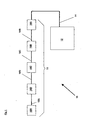
- a fibre-optic perimeter surveillance system is indicated generally by 10.
- the system 10 comprises a series of fibre-optic point sensors 16A, 16B, 16C, 16D, Vietnamese, 16N (in this example, geophones) optically linked by a series of distributed fibre-optic sensors 18B, 18C, 18D, Vietnamese, 18N to form a fibre-optic sensor array 15.
- a data link 14 couples the geophone 16A to an interrogation unit 12.
- the data link 14 may be a length of optical fibre, so that optical signals are passed to the interrogation unit 12, or alternatively it may comprise a detector which converts optical signals into electrical signals and either a fixed electrical, or wireless, link to the interrogation unit 12.
- the distributed fibre-optic sensors 18B, 18C, 18D, Vietnamese, 18N each have a physical length of 100m. There are 250 geophones in the array 15, so that the separation of geophones 16A, 16N may be up to approximately 24.9km.
- Each of the geophones 16A, 16B, 16C, 16D, Vietnamese, 16N comprises approximately 100m of optical fibre wound onto a flexural disc, and is able to measure acceleration and displacement via strain induced in the fibre.
- Each of the distributed sensors 18B, 18C, 18D, Vietnamese, 18N comprises 100m of optical fibre packaged within a cable and can measure pressure on, or bend of, the cable, also via strain induced on the fibre.
- the array 15 may be arranged in any desired configuration, for example it may be arranged around a closed path to provide perimeter surveillance for e.g. a building; alternatively it may be arranged in a linear manner to provide information on the location of a person/object crossing a straight line defined by the array 15.
- the system 10 operates as follows. When a person or object crosses a line or perimeter on or underneath which the array 15 is positioned, a force resulting from the person's or object's weight (plus possibly also a force resulting from a change in momentum if there is an impact) is applied to the sensor array. This causes radiation within a distributed fibre-optic sensor corresponding to the location where the person/object crosses to be reflected back to geophone 16A and a corresponding signal giving approximate location is passed to the interrogation unit 12. More particularly the interrogation unit 12 is able to identify that a crossing has occurred somewhere along the length of the array 15. Radiation is also reflected back from the geophones at either end of that distributed sensor, and corresponding signals are also passed to the interrogation unit 12.
- the interrogation unit 12 carries out triangulation of the signals received from the distributed sensor and the geophones at either end of it to accurately determine the location along the array 15 at which the person/object has crossed on the basis of the time at which signals are received.
- the point fibre-optic sensors are geophones, however other types of fibre-optic point sensor may be used.
- the number of point and distributed sensors may vary according to both the length of a perimeter or path which is desired to be monitored, and the accuracy with which it is desired to locate intruder events.
- the simplest fibre-optic sensor of the invention would comprise a single distributed sensor having a point sensor at each end.
- the known distance is between 20m and 50m.
- the known distance refers to the physical separation of the fibre optic sensors and is defined by the optical path length of the optical fibre between each sensor and the length of fibre used in each accelerometer.
Abstract
Description
- The present invention relates to fibre-optic surveillance systems, particularly fibre-optic perimeter surveillance systems.
- It is known to use optical fibres as sensing elements to detect pressure, strain etc, with conditions external to an optical fibre being inferred from changes in characteristics, such as amplitude, frequency or polarisation, in light output from the fibre. An example is the pressure sensor described in European Patent number 0 365 062.
- One approach to perimeter surveillance is to arrange a single length of optical fibre below ground level around a perimeter to be monitored, and to couple radiation from an LED or laser-diode into the fibre. Pressure on the fibre due to the weight of a person, vehicle or other object crossing a perimeter defined by the fibre causes a change in the amount of radiation back-scattered within the fibre (due to bending of the fibre), and hence the presence of an intruder can be detected. However, such a system has three significant disadvantages, namely (i) the position at which an intruder crosses the perimeter cannot be determined accurately, (ii) a significant false-alarm rate, (iii) no information is given about the nature if the intruding person or object and (iv) an inability to multiplex multiple sensing zones on a single fibre. Alternatively, the transmission of the fibre may be monitored as described in US patent 4 812 645. This types of system has similar drawbacks.
- Optical fibre interferometric sensors can be used to detect pressure and vibration. When a length of optical fibre is subjected to an external pressure the fibre is deformed. This deformation alters the optical path length of the fibre, which can be detected as a change in phase of light passing along the fibre. As it is possible to analyse for very small changes in phase, optical fibre sensors are extremely sensitive to applied pressure. Such a sensor is described as an interferometric sensor. This high sensitivity allows optical fibre sensors to be used for example, in acoustic hydrophones where sound waves with intensities equivalent to a pressure of 10-4 Pa are routinely detectable. Published UK patent application 2 262 803 describes an interferometric system having a serial array of distributed fibre-optic sensors, however such a system provides no accurate positional information about an intruder or information relating to the nature of the intruder.
- Published UK patent application 2 176 364 discloses a serial array of localised fibre-optic sensors. This system is only able to provide detection if an intruding person, vehicle etc passes one of the localised sensors.
- US patent US 5 140 154 discloses an inline fibre optic sensor array with intermediate fibre optic delay elements which temporally decouple signals received from the individual sensor units.
- According to a first aspect of the invention, these problems are ameliorated by a fibre-optic sensor array for a surveillance system characterised in that the sensor array comprises a at least two fibre-optic point sensors, in which each pair of successive point sensors are linked by a distributed fibre-optic sensor.
- Optical fibre sensors have the advantage that they can be multiplexed without recourse to local electronics. Interferometric sensors can also be formed into distributed sensors with a length sufficient to cover that of typical security zone perimeters (20-100m). By adopting this hybrid approach of point sensors and interstitial distributed sensors the system benefits from a high detection efficiency.
- A second aspect of the invention provides a fibre-optic surveillance system characterised in that the system comprises a fibre optic sensor of the invention connected to an interrogation system adapted to respond to an optical phase shift in at least one sensor of the array due to a force applied to that sensor and to establish the position the position at which said force is applied.
- The force could be applied by a person, animal, vehicle or other object crossing a path which is under surveillance, with the sensor array being positioned on or near the path, or underneath it.
- This provides a low cost, reliable fibre-optic surveillance system which is suitable for perimeter monitoring and which can be highly multiplexed. Remote interrogation is possible so neither local electronics nor local electrical power are required.
- The fibre-optic sensor array may be connected to the interrogation system by a fibre-optic cable or alternatively by a transducer and a wire cable.
- The fibre-optic point sensors may comprise optical fibre wound into a flexural disc, or may for example be geophones.
- Alternatively the fibre-optic point sensors may be fibre-optic accelerometers. The need to monitor extremely low levels of vibration in security and seismic survey has spurred the development of ever more sensitive accelerometers. Fibre optic technology has been applied to this particular field in the form of fibre-optic accelerometers based on interferometric techniques. The compliant cylinder approach to the design of a fibre-optic accelerometer is particularly effective when incorporated in such an interferometer. In one known approach a seismic mass is held in place by two compliant cylinders and around the circumference of each cylinder there being wound a single mode optical fibre, which form the arms of an interferometer. In another approach, a single compliant cylinder loaded with a seismic mass is wound circumferentially with an optical fibre.
- The distributed fibre optic sensors preferably comprise optical fibre packages for measuring pressure on, or bend, of the distributed sensors.
- Preferably, the interrogation system comprises a reflectometric interferometric interrogation system, more preferably the interferometric interrogation system comprises a pulsed reflectometric interferometric interrogation system in which Time Division Multiplexing (TDM) is used to distinguish individual sensors. This is a very efficient multiplexing architecture that can be used with distributed and point sensors. Furthermore wavelength Division multiplexing (WDM) can be used to increasing the number of sensors multiplexed on a single fibre further.
- Alternatively, the interferometric interrogation system may comprise a Rayleigh backscatter interferometric interrogation system, with a pulsed Rayleigh backscatter interferometric interrogation system being particularly preferred.
- A non-Rayleigh backscattering reflectometric system relies upon discrete reflectors between sensors. These are comparatively expensive components, which may add to the cost of the overall system. In contrast, Rayleigh backscattering relies on reflection of light from inhomogeneities in the optical fibre. This removes the need for discrete reflectors, reducing the overall cost of the system. However, the data collected from such a system requires more complex analysis than a reflectometric interrogation system.
- A third aspect of the invention provides a method of establishing the position at which an object moving on the earth's surface crosses a closed path, or an open path of fixed length, thereon, characterised in that the method comprises the steps of
- (i) positioning a sensor according to claim 1 on or below said path; and
- (ii) analysing optical signals received from the sensor to establish the position of the object along the path, or the position at which the object has crossed said path.
- The optical signals are preferably analysed by measuring the delay between the signals received from adjacent fibre-optic points sensors along the array and combining these signals with the signal from the distributed fibre-optic array linking those fibre-optic point sensors to locate and confirm the said position.
- An embodiment of the invention are described below by way of example only and with reference to the accompanying drawing in which schematically illustrates a fibre-optic perimeter surveillance system according to the invention.
- In Figure 1, a fibre-optic perimeter surveillance system according to the invention is indicated generally by 10. The
system 10 comprises a series of fibre-optic point sensors optic sensors optic sensor array 15. Adata link 14 couples thegeophone 16A to an interrogation unit 12. Thedata link 14 may be a length of optical fibre, so that optical signals are passed to the interrogation unit 12, or alternatively it may comprise a detector which converts optical signals into electrical signals and either a fixed electrical, or wireless, link to the interrogation unit 12. - The distributed fibre-
optic sensors array 15, so that the separation ofgeophones - Each of the
geophones distributed sensors - The
array 15 may be arranged in any desired configuration, for example it may be arranged around a closed path to provide perimeter surveillance for e.g. a building; alternatively it may be arranged in a linear manner to provide information on the location of a person/object crossing a straight line defined by thearray 15. - The
system 10 operates as follows. When a person or object crosses a line or perimeter on or underneath which thearray 15 is positioned, a force resulting from the person's or object's weight (plus possibly also a force resulting from a change in momentum if there is an impact) is applied to the sensor array. This causes radiation within a distributed fibre-optic sensor corresponding to the location where the person/object crosses to be reflected back togeophone 16A and a corresponding signal giving approximate location is passed to the interrogation unit 12. More particularly the interrogation unit 12 is able to identify that a crossing has occurred somewhere along the length of thearray 15. Radiation is also reflected back from the geophones at either end of that distributed sensor, and corresponding signals are also passed to the interrogation unit 12. The interrogation unit 12 carries out triangulation of the signals received from the distributed sensor and the geophones at either end of it to accurately determine the location along thearray 15 at which the person/object has crossed on the basis of the time at which signals are received. By using data from both types of sensor, it is possible to provide much more accurate classification of the person/object than is achievable through use of one sensor type alone. Improved classification results in a lower false-alarm rate. - In the
example system 10, the point fibre-optic sensors are geophones, however other types of fibre-optic point sensor may be used. - The number of point and distributed sensors may vary according to both the length of a perimeter or path which is desired to be monitored, and the accuracy with which it is desired to locate intruder events. The simplest fibre-optic sensor of the invention would comprise a single distributed sensor having a point sensor at each end.
- Given that the detection range of a person walking using a ground mounted fibre optic accelerometer can be >30m in certain ground types, an array of accelerometers positioned say 40m apart will ensure full coverage of a perimeter.
- By comparing signals received on adjacent accelerometers and measuring the time difference between common features on the signal it is possible to accurately calculate the position of the intrusion along the length of the interstitial fibre.
- Further temporal and frequency analysis of the accelerometer signals and the singles received from the distributed interstitial sensing cable enable intrusion classification , thereby reducing the system false alarm rate.
- Suitably, the known distance is between 20m and 50m. The known distance refers to the physical separation of the fibre optic sensors and is defined by the optical path length of the optical fibre between each sensor and the length of fibre used in each accelerometer.
Claims (16)
- A fibre-optic sensor array (15) for a surveillance system (10) characterised in that the sensor array comprises at least two fibre-optic point sensors (16), in which each pair of successive point sensors is linked by a distributed fibre-optic sensor (18).
- A fibre-optic surveillance system (10) characterised in that the system comprises a fibre optic sensor array (15) according to claim 1 connected to an interrogation system (12) which is adapted to respond to an optical phase shift in at least one sensor of the array due to a force applied to that sensor and to establish the position at which said force is applied.
- A fibre-optic surveillance system according to claim 2 wherein the fibre-optic sensor array is connected to the interrogation system by a fibre-optic cable.
- A fibre-optic surveillance system according to claim 2 wherein the fibre-optic sensor array is connected to the interrogation system by a transducer and a wire cable.
- A fibre-optic surveillance system according to claim 2 wherein the fibre-optic points sensors comprise optical fibre wound into a flexural disc.
- A fibre-optic surveillance system according to claim 2 wherein the fibre-optic points sensors are geophones.
- A fibre-optic surveillance system according to claim 2 wherein each fibre-optic point sensors comprises a fibre-optic accelerometer.
- A fibre-optic surveillance system according to claim 2 wherein the distributed fibre optic sensors comprise optical fibre packages within a cable to measure pressure on or bend of the cable.
- The system of claim 2 wherein the interrogation system comprises an interferometric interrogation system.
- The system of claim 9 wherein the interferometric interrogation system comprises a reflectometric interferometric interrogation system.
- The system of claim 10 wherein the reflectometric interferometric interrogation system comprises a pulsed reflectometric interferometric interrogation system.
- The system of claim 11 wherein the pulsed reflectometric interferometric interrogation system employs time-division multiplexing to distinguish individual sensors.
- The system of claim 2 wherein the interrogation system comprises a Rayleigh-backscatter interrogation system.
- The system of claim 13 wherein the Rayleigh-backscatter interrogation system comprises a pulsed Rayleigh-backscatter interrogation system.
- A method of establishing the position at which an object moving on a surface crosses a closed path, or an open path of fixed length, thereon, characterised in that the method comprises the steps of(i) positioning a sensor according to claim 1 on or below said path; and(ii) analysing optical signals received from the sensor to establish the position of the object along the path, or the position at which the object has crossed said path.
- A method according to claim 15 wherein the optical signals are analysed by measuring the delay between the signals received from adjacent fibre-optic points sensors along the array and combining these signals with the signal from the distributed fibre-optic array linking those fibre-optic point sensors to locate and confirm the said position.
Applications Claiming Priority (2)
| Application Number | Priority Date | Filing Date | Title |
|---|---|---|---|
| GB0322351A GB2406376A (en) | 2003-09-24 | 2003-09-24 | Surveillance system including serial array of fiber optic point sensors |
| PCT/GB2004/004076 WO2005031270A1 (en) | 2003-09-24 | 2004-09-24 | Fibre-optic surveillance system |
Publications (2)
| Publication Number | Publication Date |
|---|---|
| EP1664682A1 EP1664682A1 (en) | 2006-06-07 |
| EP1664682B1 true EP1664682B1 (en) | 2007-03-07 |
Family
ID=29266572
Family Applications (1)
| Application Number | Title | Priority Date | Filing Date |
|---|---|---|---|
| EP04768620A Active EP1664682B1 (en) | 2003-09-24 | 2004-09-24 | Fibre-optic surveillance system |
Country Status (9)
| Country | Link |
|---|---|
| US (1) | US7965909B2 (en) |
| EP (1) | EP1664682B1 (en) |
| JP (1) | JP4526537B2 (en) |
| CN (1) | CN100516781C (en) |
| AT (1) | ATE356337T1 (en) |
| DE (1) | DE602004005224T2 (en) |
| GB (1) | GB2406376A (en) |
| IL (1) | IL174411A (en) |
| WO (1) | WO2005031270A1 (en) |
Families Citing this family (15)
| Publication number | Priority date | Publication date | Assignee | Title |
|---|---|---|---|---|
| GB0401053D0 (en) * | 2004-01-17 | 2004-02-18 | Qinetiq Ltd | Improvements in and relating to accelerometers |
| CA2610375A1 (en) * | 2005-05-23 | 2006-11-30 | Lxsix Photonics Inc. | Methods and apparatuses for obtaining information regarding sensors in optical paths |
| CN102123899B (en) | 2008-06-17 | 2013-09-25 | 韦尔-琼斯工程顾问有限公司 | System and method for detecting rock fall |
| GB2473785B (en) * | 2008-12-22 | 2014-08-20 | Perimeter Security Ind Pty Ltd | Intruder detection system |
| CA2760662C (en) | 2009-05-27 | 2017-04-25 | Qinetiq Limited | Fracture monitoring |
| US8345229B2 (en) * | 2009-09-28 | 2013-01-01 | At&T Intellectual Property I, L.P. | Long distance optical fiber sensing system and method |
| GB0917150D0 (en) * | 2009-09-30 | 2009-11-11 | Qinetiq Ltd | Phase based sensing |
| GB201112161D0 (en) * | 2011-07-15 | 2011-08-31 | Qinetiq Ltd | Portal monitoring |
| CN107976709B (en) * | 2011-12-15 | 2019-07-16 | 国际壳牌研究有限公司 | (DAS) combine detection transverse direction acoustical signal is sensed with optical fiber distributed acoustic |
| GB201122229D0 (en) | 2011-12-23 | 2012-02-01 | Qinetiq Ltd | Seismic monitoring |
| CN103489275B (en) * | 2013-08-29 | 2016-12-28 | 广东复安科技发展有限公司 | A kind of monitoring circuit improving optical fiber distance monitoring positioning precision and method |
| CN103743421B (en) * | 2013-12-31 | 2016-05-18 | 上海华魏光纤传感技术有限公司 | Based on many method for sensing of single optical fibre |
| WO2021106025A1 (en) * | 2019-11-25 | 2021-06-03 | 日本電気株式会社 | Position detection device and position detection method |
| US11619541B2 (en) * | 2020-04-14 | 2023-04-04 | Nec Corporation | Vehicle speed, direction, and size measurement using temporal distributed fiber optic sensing |
| CN112432694B (en) * | 2020-11-06 | 2021-11-02 | 中冶建筑研究总院有限公司 | Industrial plant power monitoring method based on distributed optical fiber sensor |
Family Cites Families (24)
| Publication number | Priority date | Publication date | Assignee | Title |
|---|---|---|---|---|
| US4812645A (en) * | 1981-08-24 | 1989-03-14 | G2 Systems Corporation | Structural monitoring system using fiber optics |
| EP0082820A3 (en) * | 1981-12-21 | 1984-03-21 | Battelle Memorial Institute | Optical fibre pressure detector |
| US5991479A (en) * | 1984-05-14 | 1999-11-23 | Kleinerman; Marcos Y. | Distributed fiber optic sensors and systems |
| GB8514858D0 (en) * | 1985-06-12 | 1985-07-17 | Gen Electric Co Plc | Sensor devices |
| FR2637080B1 (en) * | 1988-09-27 | 1990-11-09 | Labo Electronique Physique | FIBER OPTIC PRESSURE SENSOR |
| JPH02242119A (en) * | 1989-03-15 | 1990-09-26 | Sumitomo Electric Ind Ltd | Optical fiber displacement measuring system |
| US5140154A (en) * | 1991-01-16 | 1992-08-18 | The United States Of America As Represented By The Secretary Of The Navy | Inline fiber optic sensor arrays with delay elements coupled between sensor units |
| US5134386A (en) * | 1991-01-31 | 1992-07-28 | Arbus Inc. | Intruder detection system and method |
| GB2262803A (en) * | 1991-12-24 | 1993-06-30 | Marconi Gec Ltd | An optical fibre sensor array |
| US5451772A (en) * | 1994-01-13 | 1995-09-19 | Mechanical Technology Incorporated | Distributed fiber optic sensor |
| US5710648A (en) * | 1995-12-29 | 1998-01-20 | Lucent Technologies Inc. | Optical communication system and remote sensor interrogation |
| US6449400B1 (en) * | 1996-06-21 | 2002-09-10 | Kabushiki Gaisha Inter Action | Sensing optical fiber and sensor system |
| TW323415B (en) * | 1996-11-29 | 1997-12-21 | Defence Dept Chung Shan Inst | The time-division multiplexing of polarization-insensitive fiber optic Michelson interferometric sensors |
| GB9700269D0 (en) * | 1997-01-08 | 1997-02-26 | York Sensors Ltd | Improvements to optical time domain reflectometry |
| US6691584B2 (en) * | 1999-07-02 | 2004-02-17 | Weatherford/Lamb, Inc. | Flow rate measurement using unsteady pressures |
| US6575033B1 (en) * | 1999-10-01 | 2003-06-10 | Weatherford/Lamb, Inc. | Highly sensitive accelerometer |
| US6813962B2 (en) * | 2000-03-07 | 2004-11-09 | Weatherford/Lamb, Inc. | Distributed sound speed measurements for multiphase flow measurement |
| US6498769B1 (en) * | 2000-08-04 | 2002-12-24 | Input/Output, Inc. | Method and apparatus for a non-oil-filled towed array with a novel hydrophone design and uniform buoyancy technique |
| GB0103665D0 (en) * | 2001-02-15 | 2001-03-28 | Secr Defence | Road traffic monitoring system |
| JP3860488B2 (en) * | 2002-03-01 | 2006-12-20 | 東京電力株式会社 | Wide-area strain distribution measurement system |
| GB2386183A (en) * | 2002-03-05 | 2003-09-10 | Qinetiq Ltd | Optical sensor assembly |
| US7187620B2 (en) * | 2002-03-22 | 2007-03-06 | Schlumberger Technology Corporation | Method and apparatus for borehole sensing |
| WO2004020789A2 (en) * | 2002-08-30 | 2004-03-11 | Sensor Highway Limited | Method and apparatus for logging a well using a fiber optic line and sensors |
| US7036601B2 (en) * | 2002-10-06 | 2006-05-02 | Weatherford/Lamb, Inc. | Apparatus and method for transporting, deploying, and retrieving arrays having nodes interconnected by sections of cable |
-
2003
- 2003-09-24 GB GB0322351A patent/GB2406376A/en not_active Withdrawn
-
2004
- 2004-09-24 US US10/573,671 patent/US7965909B2/en active Active
- 2004-09-24 CN CNB2004800276209A patent/CN100516781C/en active Active
- 2004-09-24 WO PCT/GB2004/004076 patent/WO2005031270A1/en active IP Right Grant
- 2004-09-24 AT AT04768620T patent/ATE356337T1/en not_active IP Right Cessation
- 2004-09-24 DE DE602004005224T patent/DE602004005224T2/en active Active
- 2004-09-24 EP EP04768620A patent/EP1664682B1/en active Active
- 2004-09-24 JP JP2006527475A patent/JP4526537B2/en not_active Expired - Fee Related
-
2006
- 2006-03-20 IL IL174411A patent/IL174411A/en active IP Right Grant
Also Published As
| Publication number | Publication date |
|---|---|
| IL174411A (en) | 2010-04-29 |
| EP1664682A1 (en) | 2006-06-07 |
| DE602004005224T2 (en) | 2007-06-21 |
| WO2005031270A1 (en) | 2005-04-07 |
| JP4526537B2 (en) | 2010-08-18 |
| CN1856694A (en) | 2006-11-01 |
| IL174411A0 (en) | 2006-08-01 |
| ATE356337T1 (en) | 2007-03-15 |
| JP2007506960A (en) | 2007-03-22 |
| CN100516781C (en) | 2009-07-22 |
| US20060257066A1 (en) | 2006-11-16 |
| US7965909B2 (en) | 2011-06-21 |
| GB0322351D0 (en) | 2003-10-22 |
| DE602004005224D1 (en) | 2007-04-19 |
| GB2406376A (en) | 2005-03-30 |
Similar Documents
| Publication | Publication Date | Title |
|---|---|---|
| IL174411A (en) | Fibre-optic surveillance system | |
| Allwood et al. | Optical fiber sensors in physical intrusion detection systems: A review | |
| US8755643B2 (en) | Fibre optic sensor package | |
| CA2780673C (en) | Fibre optic distributed sensing | |
| US9599272B2 (en) | Monitoring of the position of a pipe inspection tool in a pipeline | |
| US10352763B2 (en) | Detection of moving objects | |
| EP2499471B1 (en) | Improvements in distributed sensing | |
| RU2518978C2 (en) | Fibre-optic acoustic measurement | |
| CA2859092C (en) | Seismic monitoring | |
| EA022899B1 (en) | Improvements in distributed fibre optic sensing | |
| JP2010515094A (en) | Fault-tolerant distributed optical fiber intrusion detection | |
| US7122783B1 (en) | Seismic activity monitor based on optical fiber Bragg gratings | |
| US5021766A (en) | Intrusion detection system | |
| Zhang et al. | Fiber Bragg grating sensors for seismic wave detection | |
| US20060239603A1 (en) | Distributed sensor system coupled with a plurality of secondary sensors | |
| Zhang et al. | Unattended ground sensor based on fiber Bragg grating technology | |
| Abdallah et al. | Low-cost real-time fiber optic sensor for intrusion detection | |
| Kirkendall | Distributed acoustic and seismic sensing | |
| CN113295259A (en) | Distributed optical fiber sensing system |
Legal Events
| Date | Code | Title | Description |
|---|---|---|---|
| PUAI | Public reference made under article 153(3) epc to a published international application that has entered the european phase |
Free format text: ORIGINAL CODE: 0009012 |
|
| 17P | Request for examination filed |
Effective date: 20060324 |
|
| AK | Designated contracting states |
Kind code of ref document: A1 Designated state(s): AT BE BG CH CY CZ DE DK EE ES FI FR GB GR HU IE IT LI LU MC NL PL PT RO SE SI SK TR |
|
| GRAP | Despatch of communication of intention to grant a patent |
Free format text: ORIGINAL CODE: EPIDOSNIGR1 |
|
| DAX | Request for extension of the european patent (deleted) | ||
| GRAS | Grant fee paid |
Free format text: ORIGINAL CODE: EPIDOSNIGR3 |
|
| GRAA | (expected) grant |
Free format text: ORIGINAL CODE: 0009210 |
|
| AK | Designated contracting states |
Kind code of ref document: B1 Designated state(s): AT BE BG CH CY CZ DE DK EE ES FI FR GB GR HU IE IT LI LU MC NL PL PT RO SE SI SK TR |
|
| PG25 | Lapsed in a contracting state [announced via postgrant information from national office to epo] |
Ref country code: SI Free format text: LAPSE BECAUSE OF FAILURE TO SUBMIT A TRANSLATION OF THE DESCRIPTION OR TO PAY THE FEE WITHIN THE PRESCRIBED TIME-LIMIT Effective date: 20070307 Ref country code: BE Free format text: LAPSE BECAUSE OF FAILURE TO SUBMIT A TRANSLATION OF THE DESCRIPTION OR TO PAY THE FEE WITHIN THE PRESCRIBED TIME-LIMIT Effective date: 20070307 Ref country code: NL Free format text: LAPSE BECAUSE OF FAILURE TO SUBMIT A TRANSLATION OF THE DESCRIPTION OR TO PAY THE FEE WITHIN THE PRESCRIBED TIME-LIMIT Effective date: 20070307 Ref country code: AT Free format text: LAPSE BECAUSE OF FAILURE TO SUBMIT A TRANSLATION OF THE DESCRIPTION OR TO PAY THE FEE WITHIN THE PRESCRIBED TIME-LIMIT Effective date: 20070307 Ref country code: PL Free format text: LAPSE BECAUSE OF FAILURE TO SUBMIT A TRANSLATION OF THE DESCRIPTION OR TO PAY THE FEE WITHIN THE PRESCRIBED TIME-LIMIT Effective date: 20070307 Ref country code: FI Free format text: LAPSE BECAUSE OF FAILURE TO SUBMIT A TRANSLATION OF THE DESCRIPTION OR TO PAY THE FEE WITHIN THE PRESCRIBED TIME-LIMIT Effective date: 20070307 Ref country code: CH Free format text: LAPSE BECAUSE OF FAILURE TO SUBMIT A TRANSLATION OF THE DESCRIPTION OR TO PAY THE FEE WITHIN THE PRESCRIBED TIME-LIMIT Effective date: 20070307 Ref country code: LI Free format text: LAPSE BECAUSE OF FAILURE TO SUBMIT A TRANSLATION OF THE DESCRIPTION OR TO PAY THE FEE WITHIN THE PRESCRIBED TIME-LIMIT Effective date: 20070307 |
|
| REG | Reference to a national code |
Ref country code: GB Ref legal event code: FG4D |
|
| REG | Reference to a national code |
Ref country code: CH Ref legal event code: EP |
|
| REF | Corresponds to: |
Ref document number: 602004005224 Country of ref document: DE Date of ref document: 20070419 Kind code of ref document: P |
|
| REG | Reference to a national code |
Ref country code: IE Ref legal event code: FG4D |
|
| PG25 | Lapsed in a contracting state [announced via postgrant information from national office to epo] |
Ref country code: SE Free format text: LAPSE BECAUSE OF FAILURE TO SUBMIT A TRANSLATION OF THE DESCRIPTION OR TO PAY THE FEE WITHIN THE PRESCRIBED TIME-LIMIT Effective date: 20070607 |
|
| PG25 | Lapsed in a contracting state [announced via postgrant information from national office to epo] |
Ref country code: ES Free format text: LAPSE BECAUSE OF FAILURE TO SUBMIT A TRANSLATION OF THE DESCRIPTION OR TO PAY THE FEE WITHIN THE PRESCRIBED TIME-LIMIT Effective date: 20070618 |
|
| PG25 | Lapsed in a contracting state [announced via postgrant information from national office to epo] |
Ref country code: PT Free format text: LAPSE BECAUSE OF FAILURE TO SUBMIT A TRANSLATION OF THE DESCRIPTION OR TO PAY THE FEE WITHIN THE PRESCRIBED TIME-LIMIT Effective date: 20070807 |
|
| ET | Fr: translation filed | ||
| NLV1 | Nl: lapsed or annulled due to failure to fulfill the requirements of art. 29p and 29m of the patents act | ||
| REG | Reference to a national code |
Ref country code: CH Ref legal event code: PL |
|
| PG25 | Lapsed in a contracting state [announced via postgrant information from national office to epo] |
Ref country code: SK Free format text: LAPSE BECAUSE OF FAILURE TO SUBMIT A TRANSLATION OF THE DESCRIPTION OR TO PAY THE FEE WITHIN THE PRESCRIBED TIME-LIMIT Effective date: 20070307 |
|
| PG25 | Lapsed in a contracting state [announced via postgrant information from national office to epo] |
Ref country code: CZ Free format text: LAPSE BECAUSE OF FAILURE TO SUBMIT A TRANSLATION OF THE DESCRIPTION OR TO PAY THE FEE WITHIN THE PRESCRIBED TIME-LIMIT Effective date: 20070307 Ref country code: RO Free format text: LAPSE BECAUSE OF FAILURE TO SUBMIT A TRANSLATION OF THE DESCRIPTION OR TO PAY THE FEE WITHIN THE PRESCRIBED TIME-LIMIT Effective date: 20070307 |
|
| PLBE | No opposition filed within time limit |
Free format text: ORIGINAL CODE: 0009261 |
|
| STAA | Information on the status of an ep patent application or granted ep patent |
Free format text: STATUS: NO OPPOSITION FILED WITHIN TIME LIMIT |
|
| PG25 | Lapsed in a contracting state [announced via postgrant information from national office to epo] |
Ref country code: DK Free format text: LAPSE BECAUSE OF FAILURE TO SUBMIT A TRANSLATION OF THE DESCRIPTION OR TO PAY THE FEE WITHIN THE PRESCRIBED TIME-LIMIT Effective date: 20070307 |
|
| 26N | No opposition filed |
Effective date: 20071210 |
|
| PG25 | Lapsed in a contracting state [announced via postgrant information from national office to epo] |
Ref country code: GR Free format text: LAPSE BECAUSE OF FAILURE TO SUBMIT A TRANSLATION OF THE DESCRIPTION OR TO PAY THE FEE WITHIN THE PRESCRIBED TIME-LIMIT Effective date: 20070608 Ref country code: MC Free format text: LAPSE BECAUSE OF NON-PAYMENT OF DUE FEES Effective date: 20070930 |
|
| PG25 | Lapsed in a contracting state [announced via postgrant information from national office to epo] |
Ref country code: IE Free format text: LAPSE BECAUSE OF NON-PAYMENT OF DUE FEES Effective date: 20070924 |
|
| PG25 | Lapsed in a contracting state [announced via postgrant information from national office to epo] |
Ref country code: EE Free format text: LAPSE BECAUSE OF FAILURE TO SUBMIT A TRANSLATION OF THE DESCRIPTION OR TO PAY THE FEE WITHIN THE PRESCRIBED TIME-LIMIT Effective date: 20070307 |
|
| PG25 | Lapsed in a contracting state [announced via postgrant information from national office to epo] |
Ref country code: CY Free format text: LAPSE BECAUSE OF FAILURE TO SUBMIT A TRANSLATION OF THE DESCRIPTION OR TO PAY THE FEE WITHIN THE PRESCRIBED TIME-LIMIT Effective date: 20070307 |
|
| PG25 | Lapsed in a contracting state [announced via postgrant information from national office to epo] |
Ref country code: LU Free format text: LAPSE BECAUSE OF NON-PAYMENT OF DUE FEES Effective date: 20070924 Ref country code: BG Free format text: LAPSE BECAUSE OF FAILURE TO SUBMIT A TRANSLATION OF THE DESCRIPTION OR TO PAY THE FEE WITHIN THE PRESCRIBED TIME-LIMIT Effective date: 20070607 |
|
| PG25 | Lapsed in a contracting state [announced via postgrant information from national office to epo] |
Ref country code: HU Free format text: LAPSE BECAUSE OF FAILURE TO SUBMIT A TRANSLATION OF THE DESCRIPTION OR TO PAY THE FEE WITHIN THE PRESCRIBED TIME-LIMIT Effective date: 20070908 Ref country code: TR Free format text: LAPSE BECAUSE OF FAILURE TO SUBMIT A TRANSLATION OF THE DESCRIPTION OR TO PAY THE FEE WITHIN THE PRESCRIBED TIME-LIMIT Effective date: 20070307 |
|
| REG | Reference to a national code |
Ref country code: DE Ref legal event code: R081 Ref document number: 602004005224 Country of ref document: DE Owner name: OPTASENSE HOLDINGS LTD., GB Free format text: FORMER OWNER: QINETIQ LTD., LONDON, GB Effective date: 20121122 Ref country code: DE Ref legal event code: R082 Ref document number: 602004005224 Country of ref document: DE Representative=s name: BEETZ & PARTNER PATENT- UND RECHTSANWAELTE, DE Effective date: 20121122 Ref country code: DE Ref legal event code: R081 Ref document number: 602004005224 Country of ref document: DE Owner name: OPTASENSE HOLDINGS LTD., FARNBOROUGH, GB Free format text: FORMER OWNER: QINETIQ LTD., LONDON, GB Effective date: 20121122 Ref country code: DE Ref legal event code: R082 Ref document number: 602004005224 Country of ref document: DE Representative=s name: BEETZ & PARTNER MBB, DE Effective date: 20121122 Ref country code: DE Ref legal event code: R082 Ref document number: 602004005224 Country of ref document: DE Representative=s name: BEETZ & PARTNER MBB PATENT- UND RECHTSANWAELTE, DE Effective date: 20121122 |
|
| REG | Reference to a national code |
Ref country code: FR Ref legal event code: CA Effective date: 20130218 Ref country code: FR Ref legal event code: TP Owner name: OPTASENSE HOLDINGS LIMITED, GB Effective date: 20130218 |
|
| REG | Reference to a national code |
Ref country code: GB Ref legal event code: 732E Free format text: REGISTERED BETWEEN 20130926 AND 20131002 |
|
| REG | Reference to a national code |
Ref country code: FR Ref legal event code: PLFP Year of fee payment: 12 |
|
| REG | Reference to a national code |
Ref country code: FR Ref legal event code: PLFP Year of fee payment: 13 |
|
| REG | Reference to a national code |
Ref country code: FR Ref legal event code: PLFP Year of fee payment: 14 |
|
| REG | Reference to a national code |
Ref country code: FR Ref legal event code: PLFP Year of fee payment: 15 |
|
| PGFP | Annual fee paid to national office [announced via postgrant information from national office to epo] |
Ref country code: IT Payment date: 20190909 Year of fee payment: 16 |
|
| PG25 | Lapsed in a contracting state [announced via postgrant information from national office to epo] |
Ref country code: IT Free format text: LAPSE BECAUSE OF NON-PAYMENT OF DUE FEES Effective date: 20200924 |
|
| PGFP | Annual fee paid to national office [announced via postgrant information from national office to epo] |
Ref country code: GB Payment date: 20230914 Year of fee payment: 20 |
|
| PGFP | Annual fee paid to national office [announced via postgrant information from national office to epo] |
Ref country code: FR Payment date: 20230906 Year of fee payment: 20 Ref country code: DE Payment date: 20230916 Year of fee payment: 20 |
|
| REG | Reference to a national code |
Ref country code: DE Ref legal event code: R081 Ref document number: 602004005224 Country of ref document: DE Owner name: OPTASENSE HOLDINGS LTD., CAMBERLEY, GB Free format text: FORMER OWNER: OPTASENSE HOLDINGS LTD., FARNBOROUGH, HAMPSHIRE, GB |