EP1664622B1 - Reflector - Google Patents
Reflector Download PDFInfo
- Publication number
- EP1664622B1 EP1664622B1 EP04716079A EP04716079A EP1664622B1 EP 1664622 B1 EP1664622 B1 EP 1664622B1 EP 04716079 A EP04716079 A EP 04716079A EP 04716079 A EP04716079 A EP 04716079A EP 1664622 B1 EP1664622 B1 EP 1664622B1
- Authority
- EP
- European Patent Office
- Prior art keywords
- shell
- area
- reflector
- wall
- thickness
- Prior art date
- Legal status (The legal status is an assumption and is not a legal conclusion. Google has not performed a legal analysis and makes no representation as to the accuracy of the status listed.)
- Expired - Lifetime
Links
- 238000003780 insertion Methods 0.000 claims abstract description 18
- 230000037431 insertion Effects 0.000 claims abstract description 18
- 239000000463 material Substances 0.000 claims abstract description 16
- 239000000945 filler Substances 0.000 claims description 12
- 229920000515 polycarbonate Polymers 0.000 claims description 5
- 239000004417 polycarbonate Substances 0.000 claims description 5
- 229920001169 thermoplastic Polymers 0.000 claims description 5
- 229920000642 polymer Polymers 0.000 claims description 3
- 229920006125 amorphous polymer Polymers 0.000 claims description 2
- 239000003795 chemical substances by application Substances 0.000 claims description 2
- 230000000694 effects Effects 0.000 abstract description 8
- 230000006872 improvement Effects 0.000 abstract description 5
- 230000007774 longterm Effects 0.000 abstract description 2
- 238000012546 transfer Methods 0.000 description 12
- 230000008719 thickening Effects 0.000 description 7
- 230000003247 decreasing effect Effects 0.000 description 6
- 238000004519 manufacturing process Methods 0.000 description 6
- 238000009833 condensation Methods 0.000 description 4
- 230000005494 condensation Effects 0.000 description 4
- 230000004907 flux Effects 0.000 description 4
- 238000001746 injection moulding Methods 0.000 description 4
- 230000003287 optical effect Effects 0.000 description 4
- 239000000243 solution Substances 0.000 description 3
- 238000013459 approach Methods 0.000 description 2
- 239000011521 glass Substances 0.000 description 2
- 239000012212 insulator Substances 0.000 description 2
- 238000000034 method Methods 0.000 description 2
- 229920001601 polyetherimide Polymers 0.000 description 2
- 230000008569 process Effects 0.000 description 2
- 230000005855 radiation Effects 0.000 description 2
- 230000003068 static effect Effects 0.000 description 2
- 239000000126 substance Substances 0.000 description 2
- 208000018672 Dilatation Diseases 0.000 description 1
- 238000009825 accumulation Methods 0.000 description 1
- 239000000853 adhesive Substances 0.000 description 1
- 230000001070 adhesive effect Effects 0.000 description 1
- 238000001816 cooling Methods 0.000 description 1
- 229920001577 copolymer Polymers 0.000 description 1
- 238000007599 discharging Methods 0.000 description 1
- 230000005670 electromagnetic radiation Effects 0.000 description 1
- 239000011810 insulating material Substances 0.000 description 1
- 238000009413 insulation Methods 0.000 description 1
- 239000004922 lacquer Substances 0.000 description 1
- 238000005259 measurement Methods 0.000 description 1
- 239000012528 membrane Substances 0.000 description 1
- 238000002203 pretreatment Methods 0.000 description 1
- 238000012545 processing Methods 0.000 description 1
- 229920013730 reactive polymer Polymers 0.000 description 1
- 230000009467 reduction Effects 0.000 description 1
- 230000003014 reinforcing effect Effects 0.000 description 1
- 230000006641 stabilisation Effects 0.000 description 1
- 238000011105 stabilization Methods 0.000 description 1
- 230000035882 stress Effects 0.000 description 1
- 230000008646 thermal stress Effects 0.000 description 1
- 239000004416 thermosoftening plastic Substances 0.000 description 1
- 238000001771 vacuum deposition Methods 0.000 description 1
- XLYOFNOQVPJJNP-UHFFFAOYSA-N water Substances O XLYOFNOQVPJJNP-UHFFFAOYSA-N 0.000 description 1
Images

Classifications
-
- F—MECHANICAL ENGINEERING; LIGHTING; HEATING; WEAPONS; BLASTING
- F21—LIGHTING
- F21V—FUNCTIONAL FEATURES OR DETAILS OF LIGHTING DEVICES OR SYSTEMS THEREOF; STRUCTURAL COMBINATIONS OF LIGHTING DEVICES WITH OTHER ARTICLES, NOT OTHERWISE PROVIDED FOR
- F21V29/00—Protecting lighting devices from thermal damage; Cooling or heating arrangements specially adapted for lighting devices or systems
- F21V29/50—Cooling arrangements
- F21V29/502—Cooling arrangements characterised by the adaptation for cooling of specific components
- F21V29/505—Cooling arrangements characterised by the adaptation for cooling of specific components of reflectors
-
- F—MECHANICAL ENGINEERING; LIGHTING; HEATING; WEAPONS; BLASTING
- F21—LIGHTING
- F21S—NON-PORTABLE LIGHTING DEVICES; SYSTEMS THEREOF; VEHICLE LIGHTING DEVICES SPECIALLY ADAPTED FOR VEHICLE EXTERIORS
- F21S41/00—Illuminating devices specially adapted for vehicle exteriors, e.g. headlamps
- F21S41/30—Illuminating devices specially adapted for vehicle exteriors, e.g. headlamps characterised by reflectors
- F21S41/37—Illuminating devices specially adapted for vehicle exteriors, e.g. headlamps characterised by reflectors characterised by their material, surface treatment or coatings
-
- F—MECHANICAL ENGINEERING; LIGHTING; HEATING; WEAPONS; BLASTING
- F21—LIGHTING
- F21V—FUNCTIONAL FEATURES OR DETAILS OF LIGHTING DEVICES OR SYSTEMS THEREOF; STRUCTURAL COMBINATIONS OF LIGHTING DEVICES WITH OTHER ARTICLES, NOT OTHERWISE PROVIDED FOR
- F21V7/00—Reflectors for light sources
- F21V7/22—Reflectors for light sources characterised by materials, surface treatments or coatings, e.g. dichroic reflectors
- F21V7/24—Reflectors for light sources characterised by materials, surface treatments or coatings, e.g. dichroic reflectors characterised by the material
-
- F—MECHANICAL ENGINEERING; LIGHTING; HEATING; WEAPONS; BLASTING
- F21—LIGHTING
- F21V—FUNCTIONAL FEATURES OR DETAILS OF LIGHTING DEVICES OR SYSTEMS THEREOF; STRUCTURAL COMBINATIONS OF LIGHTING DEVICES WITH OTHER ARTICLES, NOT OTHERWISE PROVIDED FOR
- F21V7/00—Reflectors for light sources
- F21V7/22—Reflectors for light sources characterised by materials, surface treatments or coatings, e.g. dichroic reflectors
- F21V7/28—Reflectors for light sources characterised by materials, surface treatments or coatings, e.g. dichroic reflectors characterised by coatings
Definitions
- the present invention relates to reflectors of headlights, fog lamps and other lighting means for vehicles, while in the field of commonly illuminating the invention relates to controlling thermal conditions in the interior of the reflector, meaningfully at least cooling the reflector, and actually also avoiding the inadmissible temperature difference between the hotest and coolest zone within the reflector.
- the invention is based on the problem, how to concieve a reflector, which should enable achieving a required luminous intensity and optical characteristics and should consist of a polymeric material, which would enable achieving an essential improvement of thermal conditions in its interior, so that despite to long-term operation the wall thereof, which consists of a polymeric material, could not be overheated in the hotest zone in the upper area above the bulb, and moreover also the negative effects, which result from the presence of an essentially cooler zone in the lower area below the bulb, would also have to be avoided.
- the term reflector describes a part of a headlight, which is mounted within a housing of such headlight or similar lighting means, and surrounds a bulb.
- the headlight namely comprises, in addition to the said reflector and a bulb, also an appropriate casing, by which in the area of its casing in appropriate manner the reflector is attached, and moreover also a translucide covering glass sheet, which is placed over the reflector in order to protect it against the influences from the outside.
- Reflector may be either spherical or elliptical or even otherwise shaped, which means that the reflection area of the reflector is formed onto a portion of surface, which belongs to a sphere, an ellipsoid or any other appropriate geometrical object.
- the reflector is a body, which is a shell from quite geometrical point of view, having a desired thickness of the wall in the radial direction thereof.
- a bulb is inserted within the reflector on a desired location, so that the heat beams, which are emitted by the bulb, are then reflected on the surface of the reflector in a desired direction.
- the term reflector for the purposes of this application relates exclusively to reflectors, which consist of polymeric materials. Such version of reflectors is intended for mass production in a relatively simple and economic manner.
- the bulb In addition to the luminiscence, the bulb also generates an essential amount of heat energy.
- two main areas may be determined within the reflector, namely the lower area below the horizontal i.e. equatorial plane, in which the bulb is placed, as well as the upper area above the said plane of the bulb.
- Reflector to which the present invention relates, consists of a polymeric material and is foreseen for headlights with housing and translucide covering glass and is merely intended for use in various vehicles.
- Polymeric reflectors which may be coated with reflection layer without any previous treatment, represent an attractive and simple solution for vehicle headlights.
- Reflection layer on the reflector is ordinary a thin metallic i.e. metallized layer, which is obtained by means of vacuum deposition.
- small lighting means e.g. by fog lamps
- the use of polymeric reflectors is limited by high temperature, which occurs on the reflector, more precisely in the upper area of the reflector, due to hot convective air column, which is moved upwards above the lighting body i.e. the bulb. This relates especially to reflectors with very small and hot surface.
- Such lighting bodies are all kinds of bulbs with filament as well as modem discharging lamps.
- the problem may occur, which relates to presence of the so-called cold zone in the lower area below the light source.
- Such zone is mostly the coolest surface within the complete headlight housing.
- the vaporized substances are condensed, which are before that evaporated from hot portions of the polymeric casing or also from the adhesive on the headlight housing.
- a certain quantity of condensed water may be present.
- Such phenomena is a consequence of the lack of heat accumulation in the lower area of the reflector, which is then the first cooled below the condensation point of the moisture, which is present in the air.
- the present invention relates to a reflector, which consists of a polymeric material, which is resistant with respect to possible deviations of form and dimensions when being exposed to an increased temperature, and comprises an internal surface, which extends adjacent to the bulb and is provided with a reflection layer.
- the said bulb is placed in the central area, where a stable insertion of such bulb is ensured by means of sufficient thickness of the wall.
- the thickness of the wall in the upper area of the shell of the reflector, which is placed above the area of insertion the bulb is smaller than the thickness of the wall in the lower area of the shell, which lies below the area of insertion the bulb.
- the thickness of the wall in the lower area of the shell of the reflector below the area of insertion the bulb is 1,5-times do 2-times greater than the thickness of the wall in the upper area of the shell of the reflector above the area of insertion the bulb.
- the reflector according to the invention is characterized in that at least a portion thereof, namely at least the wall thereof, consists of a thermoplastic polymer either without filling agents or with filling agents, which are smaller than 3 ⁇ m, by which appropriate resistance with respect to deviations in geometry due to increasing the temperature is ensured at least up to temperature value of 120°C.
- the reflector according to the invention is characterized in that at least a portion thereof, namely at least the wall thereof, consists of an amorphous polymer without filling agents, which belongs to the group of polycarbonates, polyethersulphones or polyeterimides.
- the said reflection layer on the internal surface of the shell is a metallized layer, especially vacuum deposited, in particular vaporized layer.
- the thickness of the wall in the upper area of the shell of the reflector above the area of insertion the bulb is 1 to 2 mm, preferably 1,4 to 1,8 mm, while the thickness of the wall in the lower area of the shell of the reflector below the area of insertion the bulb is 1,6 to 4 mm, preferably 2,2 to 3 mm.
- the reflector is suggested, by which at least two areas are characteristic, namely the upper area, in which the thickness of the wall is smaller than the thickness of the wall in the central area of the reflector, as well as the lower area, in which the thickness of the wall is greater than the thickness in the central area of the reflector, in which the bulb is inserted and which in common remains the same as by the previously known reflectors.
- the upper area in which the thickness of the wall is smaller than the thickness of the wall in the central area of the reflector
- the lower area in which the thickness of the wall is greater than the thickness in the central area of the reflector, in which the bulb is inserted and which in common remains the same as by the previously known reflectors.
- Still another embodiment of the reflector according to invention is equipped with relatively rigid carrying ring, which is either continously or discontinously arranged arround the shell of the reflector with various thickness of the wall, and which serves for attachment of the reflector within each belonging housing, so that due to the presence of the said ring an upwardly closed wedge-shaped is formed, in which then hot air may be collected.
- the said ring or also an appropriate connecting element between the said ring and the shell is equipped with at least one opening or similar passage.
- the said opening are foreseen, which may either be arranged in the top area of the carrying ring in a position, which is situated at the maximum distance above the equatorial plane, or adjacent to this area, or also in the top area of the connecting element when available between the shell and the carrying ring, or even in the top area of the said ring and in the top area of the said the carrying element between the ring and the shell, by which the thickness of the wall of the shell in the area above the equatorial plane is smaller than the thickness of the wall of the shell in the area below the equatorial plane.
- the opening may be formed either as a single opening or may also consist of a desired number of separately arranged openings.
- Still further measure in course of efficient heat transfer includes determining of appropriate roughness on the external surface of the reflector shell, which should in accordance with the invention be between 0,003 and 0,01 mm. Such roughness should be ensured on the external surface of the shell at least in the upper area of the reflector above the horizontal i.e. equatorial plane, at least essentially adjacent to the location of the bulb. Such roughness is achieved by means of presence of punctiform and/or line shaped cavities and/or projections of relatively slope triangular or trapezoidal longitudinal cross-section on the said surface.
- the thickness D 0 of the wall 10 of the shell 3 should be 2,2 mm along the complete circumference, and the heat conductivity is 0,24 W/mK; when by such thermally stressed reflector 1 the measured temperature on the external surface 14 is 168°C, then the temperature on the internal surface 13 may be spiritualally calculated, and is 204,7°C.
- a reflector 1 with equal optical characteristics and dimensions at the one hand has smaller thickness D, of the wall 10 of the reflector 1 in its upper area 11 on the other hand, by which this thickness D, is e.g. 1,7 mm, and when the measured external temperature is 167°C (which means practically the same thermal stresses), then the temperature on the internal surface 13 of the reflector 13 may be evaluated on the basis of thickness D, of the wall 10 as well as of the thermal conductivity, and should be only 195°C.
- the wall 10 is thinned along the complete upper area 11, i.e. within the complete top half of the reflector 1 above the bulb 4, then the heat flux is distributed from the hotest zone above the bulb 4 towards the other surfaces, which are available adjacent to the hotest zone.
- the most desired embodiment of the upper area 11 of the shell 3 of the reflector 3 is a thinn membrane, which is in the praxis however not really applicable.
- Manufacturing of such headlight is ordinary carried out by means of injection molding, which is bound to certain limitations, so that by smaller reflectors 1 the minimum thickness D, of the wall 10 should be at least 1 mm.
- Manufacturing by means of injection molding is no doubt the optimum choice, which should not be changed due to any other creations and requirements in reflector, which do not relate to heat transfer.
- the minimum thickness D, of the wall 10 may be varied depending on diameter of the reflector 1, requirements with respect to adaquately precise directing the light rays, or also on thermal expansion coefficient in corelation with the module of elasticity, which correspond to the material used.
- the thickness D, the wall 10 in amount of at least 1,5 mm is still acceptable, however by taking into account, that the bulb 4 is built within a rigid central area 100 and/or a lower area 12 of the reflector 1, which should however not represent any serious obstacle in course of successfully realization of the invention.
- Effects related to thickening the lower area 12 of the shell 3 of the reflector 1 may also be illustrated by means of an embodiment of reflector 1, which consists of polyetherimid and has diameter of 75 mm.
- reflector 1 completely corrresponds to the above mentioned reflector 1, in connection to which the effects related to thinning the wall 10 in the upper area 11 of the shell 3 have already been described, by taking into account, that in this case the thickness D 2 of the wall 10 is 2.2. mm and that thermal conductivity is 0,22 W/mK, which is a consequence of some lower temperature in this lower area 12 of the shell 3.
- the measured temperature on its external surface 14 is 70°C.
- the internal temperature 81.5°C is spiritualally calculated.
- the measured temperature on the external surface 14 in the lower area 12 of the shell 3 is 69°C, which is a consequence of reduction of the heat flux, whilst the temperature 83°C on the internal wall 10 within the same area 12 of the shell 3 of the reflector 1 is spiritualally calculated.
- the thickness D 2 of the wall 10 in the lower area 12 of the reflector 1 would exceed a double thickness D, of the wall 10 in the upper area 11 of the reflector 1, addition problems would arise in course of disturbances during filling the mould cavity with the melted material due to insufficient hydraulic resistance in direction towards the thicker lower area 12 of the reflector 1. Of that reason, the thickness D 2 of the wall 10 in the lower area 12 of the reflector 1 shall not exceed a double thickness D, of the wall 10 in the upper area 11 of the reflector 1.
- Combination of benefits which are obtained by means of thinning the upper area 11 and thickening the lower area 12 of the shell 3 of the reflector 1, may be analysed on the basis of a comparable reflector 1 having a diameter of 75 mm (which is the same reflector 1 as in the previously discussed embodiments, at least with respect to optical characteristics and dimensions), by which the thickness D 2 of the wall 10 in the lower area 12 is 2,8 mm, and the thickness D 1 of the wall 10 in the upper area 11 is 1,7 mm, while the thickness D 0 of the wall 10 in the central area 100 in the level of the bulb 4 i.e. in the so-called equatorial plane, is 2,2 mm.
- the measured temperature on the external surface 14 of the lower area 12 of the shell 3, which is thinned upwards and thicked downwards, is 66°C. Additional decreasing of temperature for 3°C is a consequence of thinning the upper area 11. This is no doubt valuable, since thinning the wall 10 in the upper area 11 of the shell 3 results in decreasing the temperature also in other portions, where potential sources of vaporized substances may be present, which are normally condensed in the lower part 12 of the reflector 1.
- Thickening the lower area 12 of the reflector 1 among others also leads to establishing much more stable fixation of the bulb 4 in the central area 100 and preventing its deviations from the correct position due to extension of the warmed upper area 11 of the reflector 1.
- each desired thickness D 0 , D 1 , D 2 of the wall 10 of the reflector 1 may be determined depending on local temperature. Accordingly, smaller thickness D 0 , D 1 , D 2 of the wall 10 may be foreseen in the area with higher temperature.
- the reflector 1 consists of a polymer without filling agents, or exceptionally also with filling agents, the dimensions of which do not exceed 3 ⁇ m.
- Such polymeres may namely be coated in vacuum by a metallic reflection layer 2 without applying a lacque onto the internal surface 13 before that.
- Reflector 1 by which a desired heat transfer is achieved by means of determining appropriate values of thickness D 0 , D 1 , D 2 in certain areas 11, 12, 100 of the wall 10, may no doubt also consist of reactive polymeres. These are normally filed with rough filling agents. During the manufacturing of the reflector 1, the presence of such agents normally requires appropriate pre-treatment of the inner surface 13 by applying a lacquer.
- thermoplastic polycarbonates co-polymeres of polycarbonates, polyether-sulphones and polyetherimides, all of them without any filling agents.
- thermoplastic polymeres which excel in appropriate behaviour during processing thereof by injection molding, and may moreover be regenerated i.e. recycled.
- a further embodiment which is shown in Figs. 3 to 5 , relates to a reflector 1 as well, which is manufactured of a polymeric material and consists of a carrying ring 2 and a shell 3, wherein the last one comprises a concave internal surface 13, on which appropriate reflecticve layer is foreseen, as well as a convex external surface 14.
- the said ring 2 is essentially cyllindric or thoroidal, and may be either continued or discontinued, so that it is formed of more segments, extending in the circumferential direction.
- the shell 3 of the reflector 1 comprises a tube-like projection 33, which includes appropriate opening, into which the bulb 4 is inserted with its base or bracket, which is arranged in the horizontal equatorial plane 30 and is not shown in the drawing.
- the thickness of the wall 10 in the upper area 11 of the shell 3 above the equatorial plane 30 of the reflector 1 i.e. above the bulb 4, as shown in Fig. 1 or 2 may be smaller than the thickness in the lower area 12 of the shell 3 below the said plane 30 i.e. the bulb 4, by which the heat transfer from the inside of the reflector 1 towards the outside thereof may be much more intensive, especially the transfer from the upper area 11 of the shell 3 above the said plane 30 towards the area adjacent to the external surface 14 above the said plane 30.
- an upwardly closed wedge-shaped space 23 is present between the carrying ring 2 and the outer surface 14 of the shell 3.
- the shell 3 is connected to the said ring 2 by means of a relatively thin connecting element 21, which extends continuously along the curcumference thereof.
- At least one opening 22 is foreseen at least in the upper area of the connecting element 21 between the bearing ring 2 and the shell 3, which is situated at a maximum distance from the equatorial plane 30 and enables draining of heated air, which is collected within the said wedge-shaped space 23.
- a desired decreasing of temperature within the said space 23 may be achieved, by means of which also the difference between the temperature of the internal surface 13 and the temperature of the external surface 14 is increased, on the basis of which the heat transfer from the inside of the reflector 1 towards the outside thereof becomes adequately more intensive.
- FIG. 6 A still further measurement in course of improvement the thermic conditions in the reflector 1 is shown in Fig. 6 .
- the outward surface 14 at least in the upper area 11 of the shell 3 is characterized by appropriate, in advance determined roughness, which means, that it includes cavities and projections having determined dimensions.
- a characteristic rough surface 14 is carried out in such a manner, that it includes adequately slope cavities or projections in form of pyramid and/or truncated pyramid and/or cone and/or truncated cone of appropriate depth or height ⁇ , by which such roughness essentially improves emissivity of electromagnetic radiation.
- the temperature of the wall 10 in the upper area 11 of the shell 3 is approx. 400 K, and the majority of energy, which is radiated by the reflector 1, represents radiation in the area of wavelengths between 3,5 in 25 ⁇ m.
- Appropriate roughness, which leads to improvement of emisiveness, corresponds to approximately a tenth of the maximum wavelength, which means, that the minimal depth/height ⁇ of the said cavities/projections on the surface 14 should be approximately 0,003 mm.
- roughness of the external surface 14 may also lead to forming a static air layer, which is in fact a heat insulating layer on the external surface 14 of the shell 3.
- the roughness ⁇ of the external surface 14 of the shell 3 in the upper area 11 of the reflector 1 at least adjacent to the area 100 of insertion a bulb 4 and in the neigborhood thereof should be between 0,003 and 0,01 mm.
- appropriate roughness ⁇ in the area between 0,003 and 0,01 mm on the external surface 14 of the shell 3 of the reflector 1 may be obtained by means of relatively slope punctiform cavities and/or projections, which are triangular or trapezoidal in their longitudinal cross-section and are arranged on the said surface 14.
- such cavities or projections may also be line shaped i.e. elongated, like grooves, recesses, ribs or the like.
Landscapes
- Engineering & Computer Science (AREA)
- General Engineering & Computer Science (AREA)
- Non-Portable Lighting Devices Or Systems Thereof (AREA)
- Arrangement Of Elements, Cooling, Sealing, Or The Like Of Lighting Devices (AREA)
- Aerials With Secondary Devices (AREA)
Abstract
Description
- In the field of lighting equipment for vehicles the present invention relates to reflectors of headlights, fog lamps and other lighting means for vehicles, while in the field of commonly illuminating the invention relates to controlling thermal conditions in the interior of the reflector, meaningfully at least cooling the reflector, and actually also avoiding the inadmissible temperature difference between the hotest and coolest zone within the reflector.
- The invention is based on the problem, how to concieve a reflector, which should enable achieving a required luminous intensity and optical characteristics and should consist of a polymeric material, which would enable achieving an essential improvement of thermal conditions in its interior, so that despite to long-term operation the wall thereof, which consists of a polymeric material, could not be overheated in the hotest zone in the upper area above the bulb, and moreover also the negative effects, which result from the presence of an essentially cooler zone in the lower area below the bulb, would also have to be avoided.
- For the purposes of further discussion, the term reflector describes a part of a headlight, which is mounted within a housing of such headlight or similar lighting means, and surrounds a bulb. The headlight namely comprises, in addition to the said reflector and a bulb, also an appropriate casing, by which in the area of its casing in appropriate manner the reflector is attached, and moreover also a translucide covering glass sheet, which is placed over the reflector in order to protect it against the influences from the outside. Reflector may be either spherical or elliptical or even otherwise shaped, which means that the reflection area of the reflector is formed onto a portion of surface, which belongs to a sphere, an ellipsoid or any other appropriate geometrical object. In addition, the reflector is a body, which is a shell from quite geometrical point of view, having a desired thickness of the wall in the radial direction thereof. A bulb is inserted within the reflector on a desired location, so that the heat beams, which are emitted by the bulb, are then reflected on the surface of the reflector in a desired direction. Still further, the term reflector for the purposes of this application relates exclusively to reflectors, which consist of polymeric materials. Such version of reflectors is intended for mass production in a relatively simple and economic manner.
- In addition to the luminiscence, the bulb also generates an essential amount of heat energy. When bearing in mind the thermal conditions within the reflector, two main areas may be determined within the reflector, namely the lower area below the horizontal i.e. equatorial plane, in which the bulb is placed, as well as the upper area above the said plane of the bulb.
- Reflector, to which the present invention relates, consists of a polymeric material and is foreseen for headlights with housing and translucide covering glass and is merely intended for use in various vehicles. Polymeric reflectors, which may be coated with reflection layer without any previous treatment, represent an attractive and simple solution for vehicle headlights. Reflection layer on the reflector is ordinary a thin metallic i.e. metallized layer, which is obtained by means of vacuum deposition. By small lighting means, e.g. by fog lamps, the use of polymeric reflectors is limited by high temperature, which occurs on the reflector, more precisely in the upper area of the reflector, due to hot convective air column, which is moved upwards above the lighting body i.e. the bulb. This relates especially to reflectors with very small and hot surface. Such lighting bodies are all kinds of bulbs with filament as well as modem discharging lamps.
- In addition, by certain embodiments of headlights also the problem may occur, which relates to presence of the so-called cold zone in the lower area below the light source. Such zone is mostly the coolest surface within the complete headlight housing. In such cold zone then the vaporized substances are condensed, which are before that evaporated from hot portions of the polymeric casing or also from the adhesive on the headlight housing. Especially upon several switching-on and switching-off the headlight in the cold and wet weather conditions, in such zone also a certain quantity of condensed water may be present. Such phenomena is a consequence of the lack of heat accumulation in the lower area of the reflector, which is then the first cooled below the condensation point of the moisture, which is present in the air.
- Constructors of headlights with polymeric housings as well as polymeric reflectors according to the state of the art have normally tried to avoid the problem related to hot zone above the bulb by inserting special bulbs, which generate less heat, or also by using much more expensive polymeric materials, which are resistant to higher temperature. A solution is also known, by which an aperture is foreseen on the hotest portion of the reflector, by means of which the hot air column is left away. Such approach is inadmissible by reflectors, which are intended for hermetically covering the last portion of the headlight, or also from quite aesthetical point of view. The applicant could not find any relevant patent literature, in which such problems related to the said cold zone would be described.
- By taking into account the previously exposed facts and also the known solutions, which belong to the prior art, there no doubt exists a challenge in course of appropriate stabilization of heat conditions within the polymeric reflector, however without any essential reconstruction and disturbing the existing luminiscence and other characteristics of such reflector. Accordingly, the present invention relates to a reflector, which consists of a polymeric material, which is resistant with respect to possible deviations of form and dimensions when being exposed to an increased temperature, and comprises an internal surface, which extends adjacent to the bulb and is provided with a reflection layer. The said bulb is placed in the central area, where a stable insertion of such bulb is ensured by means of sufficient thickness of the wall. According to the invention, the thickness of the wall in the upper area of the shell of the reflector, which is placed above the area of insertion the bulb, is smaller than the thickness of the wall in the lower area of the shell, which lies below the area of insertion the bulb. In a preferred embodiment, the thickness of the wall in the lower area of the shell of the reflector below the area of insertion the bulb is 1,5-times do 2-times greater than the thickness of the wall in the upper area of the shell of the reflector above the area of insertion the bulb. In addition, the reflector according to the invention is characterized in that at least a portion thereof, namely at least the wall thereof, consists of a thermoplastic polymer either without filling agents or with filling agents, which are smaller than 3 µm, by which appropriate resistance with respect to deviations in geometry due to increasing the temperature is ensured at least up to temperature value of 120°C. Furthermore, the reflector according to the invention is characterized in that at least a portion thereof, namely at least the wall thereof, consists of an amorphous polymer without filling agents, which belongs to the group of polycarbonates, polyethersulphones or polyeterimides. The said reflection layer on the internal surface of the shell is a metallized layer, especially vacuum deposited, in particular vaporized layer. In addition, the thickness of the wall in the upper area of the shell of the reflector above the area of insertion the bulb is 1 to 2 mm, preferably 1,4 to 1,8 mm, while the thickness of the wall in the lower area of the shell of the reflector below the area of insertion the bulb is 1,6 to 4 mm, preferably 2,2 to 3 mm.
- According to the invention, a quite new concept of the reflector is suggested, by which at least two areas are characteristic, namely the upper area, in which the thickness of the wall is smaller than the thickness of the wall in the central area of the reflector, as well as the lower area, in which the thickness of the wall is greater than the thickness in the central area of the reflector, in which the bulb is inserted and which in common remains the same as by the previously known reflectors. By means of thinning the wall in the upper area the heat transfer is essentially increased from the area above the bulb, which is in contact with the hot air. Polymeric material, of which the reflector consists, is namely a heat insulator. Accordingly, by thinning the wall is then the thickness of the insulator essentially reduced. On the contrary, by thickening the wall in the lower area an opposite effect is achieved, since the insulation in this area is increased. Thickening the wall in the lower area results in increasing the heat capacity in this lower area, so that condensation by switching-off the headlight is slowed-down or even displaced to other locations.
- Still another embodiment of the reflector according to invention is equipped with relatively rigid carrying ring, which is either continously or discontinously arranged arround the shell of the reflector with various thickness of the wall, and which serves for attachment of the reflector within each belonging housing, so that due to the presence of the said ring an upwardly closed wedge-shaped is formed, in which then hot air may be collected. In this connection, the said ring or also an appropriate connecting element between the said ring and the shell is equipped with at least one opening or similar passage. By means of the said opening the said wedge-shaped space above the external surface of the shell and above the carrying ring is connected with the exterior outside of the external circumference of the said ring or the connecting element, respectivelly. Various possible arrangements of the said opening are foreseen, which may either be arranged in the top area of the carrying ring in a position, which is situated at the maximum distance above the equatorial plane, or adjacent to this area, or also in the top area of the connecting element when available between the shell and the carrying ring, or even in the top area of the said ring and in the top area of the said the carrying element between the ring and the shell, by which the thickness of the wall of the shell in the area above the equatorial plane is smaller than the thickness of the wall of the shell in the area below the equatorial plane. The opening may be formed either as a single opening or may also consist of a desired number of separately arranged openings.
- Still further measure in course of efficient heat transfer includes determining of appropriate roughness on the external surface of the reflector shell, which should in accordance with the invention be between 0,003 and 0,01 mm. Such roughness should be ensured on the external surface of the shell at least in the upper area of the reflector above the horizontal i.e. equatorial plane, at least essentially adjacent to the location of the bulb. Such roughness is achieved by means of presence of punctiform and/or line shaped cavities and/or projections of relatively slope triangular or trapezoidal longitudinal cross-section on the said surface.
- Efficiency of the improved concept of the reflector in course of controlling the thermal conditions is presented by means of embodiments, which will be explained in more detail in connection with the enclosed drawings, wherein
-
Fig. 1 is a vertical cross-section of an embodiment of a circular reflector, which belongs to a fog lamp; -
Fig. 2 is a cross-section of the reflector along the plane A - A; -
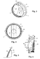
Fig. 3 is a perspective view of a further embodiment of a reflector; -
Fig. 4 is a front view of the reflector according toFig. 3 ; -
Fig. 5 is a vertical cross-section of the reflector according toFig. 3 ; and -
Fig. 6 is a detail B according toFig. 5 , from which a further possible approach as well as a corresponding embodiment may be derived. - The
metallized reflection layer 101 on theinternal surface 13 of the observed embodiment of thereflector 1, which has a diameter 75 mm and is manufactured of polyethermide, is capable to withstand a short-term temperature stress up to 200°C. By currently usedreflectors 1 having the above specified diameter, the thickness D0 of thewall 10 of theshell 3 should be 2,2 mm along the complete circumference, and the heat conductivity is 0,24 W/mK; when by such thermally stressedreflector 1 the measured temperature on theexternal surface 14 is 168°C, then the temperature on theinternal surface 13 may be matematically calculated, and is 204,7°C. When assuming, that thesame reflector 1, i.e. areflector 1 with equal optical characteristics and dimensions at the one hand, has smaller thickness D, of thewall 10 of thereflector 1 in itsupper area 11 on the other hand, by which this thickness D, is e.g. 1,7 mm, and when the measured external temperature is 167°C (which means practically the same thermal stresses), then the temperature on theinternal surface 13 of thereflector 13 may be evaluated on the basis of thickness D, of thewall 10 as well as of the thermal conductivity, and should be only 195°C. When thewall 10 is thinned along the completeupper area 11, i.e. within the complete top half of thereflector 1 above the bulb 4, then the heat flux is distributed from the hotest zone above the bulb 4 towards the other surfaces, which are available adjacent to the hotest zone. Due to improved taking-away the heat, such thinning thewall 10 in theupper area 11 of theshell 3 of thereflector 1 then results in decreasing temperature within the complete interior of the casing of a headlight and therefore indirectly in additional decreasing temperature within the hotest zone above the bulb 4. - If the
wall 10 in theupper area 11 of theshell 3 is thinned only locally in the hotest zone thereof, then increasing temperature occurs on theexternal surface 14, since the heat flux through the said area is increased. - When bearing in mind exclusively the aspects related to heat transfer, the most desired embodiment of the
upper area 11 of theshell 3 of thereflector 3 is a thinn membrane, which is in the praxis however not really applicable. Manufacturing of such headlight is ordinary carried out by means of injection molding, which is bound to certain limitations, so that bysmaller reflectors 1 the minimum thickness D, of thewall 10 should be at least 1 mm. Manufacturing by means of injection molding is no doubt the optimum choice, which should not be changed due to any other creations and requirements in reflector, which do not relate to heat transfer. However, even by manufacturing the products with thickness of thewall 10 of approx. 1 mm may still lead to serious problems, especially to inadmissible vaulting of extremely heatedinternal surface 13 in theupper area 11 of theshell 3, which is intended for receipt of thereflection layer 101. The said vaulking is a consequence of thermal dilatations in theupper area 11 of theshell 3 of the reflector in respect to less warmedcircumferential area 15 of theshell 3 of thereflector 1. On such basis, appropriate choice with respect to minimum thickness D, D1, D2 of thewall 10 of theshell 3 enables achieving a desired stiffness of thereflector 1. Providing various reinforcing means like ribs or similar additional elements on theexternal surface 14 of thereflector 1 should not be taken into account, since such ribs consist of a heat-insulating material any may therefore essentially hinder a desired heat transfer. The minimum thickness D, of thewall 10 may be varied depending on diameter of thereflector 1, requirements with respect to adaquately precise directing the light rays, or also on thermal expansion coefficient in corelation with the module of elasticity, which correspond to the material used. Nevertheless, on the basis of obtained results it may be stated, that by appropriate geometric properties of thereflector 1, the thickness D, thewall 10 in amount of at least 1,5 mm is still acceptable, however by taking into account, that the bulb 4 is built within a rigidcentral area 100 and/or alower area 12 of thereflector 1, which should however not represent any serious obstacle in course of successfully realization of the invention. - Effects related to thickening the
lower area 12 of theshell 3 of thereflector 1 may also be illustrated by means of an embodiment ofreflector 1, which consists of polyetherimid and has diameter of 75 mm. In fact,such projector 1 completely corrresponds to the above mentionedreflector 1, in connection to which the effects related to thinning thewall 10 in theupper area 11 of theshell 3 have already been described, by taking into account, that in this case the thickness D2 of thewall 10 is 2.2. mm and that thermal conductivity is 0,22 W/mK, which is a consequence of some lower temperature in thislower area 12 of theshell 3. When theshell 3 is thermally stressed, the measured temperature on itsexternal surface 14 is 70°C. The internal temperature 81.5°C is matematically calculated. By enlarging the thickness D2 of thewall 10 up to 2.8 mm, the measured temperature on theexternal surface 14 in thelower area 12 of theshell 3 is 69°C, which is a consequence of reduction of the heat flux, whilst the temperature 83°C on theinternal wall 10 within thesame area 12 of theshell 3 of thereflector 1 is matematically calculated. In each case this means at least certain improvement of conditions, especially, since the condensation process depends on small temperature differences, in particular when the operating conditions are very close to conditions, where such undesired condensation is started, which often occurs in the practice. - When bearing in mind the heat transfer, it would be ideal to ensure such temperature D2 of the
wall 10 in thelower area 12 of theshell 3 of thereflector 1, that the temperature on theinternal surface 13 of thereflector 1 would be increased up to such degree, that this temperature would not be the lowest temperature within the casing of thereflector 1. In such a way, the problem of the so-called "cold zone" might be avoid, e.g. displaced to any other area of the casing ofreflector 1, which is not so much exposed and important as the visible surface in thelower area 12 of thereflector 1. It can also be assumed, that such problem might be solved by exposing the thickest part of the casing as the low-temperature zone. However, this is in the practice unfortunately not possible, since this portion and also some other portions of the casing are due to optical or quite esthetical reasons manufactured in dark colour. These dark surfacess then intensively absorbe radiation of the light source (infra-red and visible light), so that the temperatures in the lower part of the casing of thereflector 1 are regularly higher than in thelower area 12 of thereflector 1. It may also be stated in the practice, that due to technologic limitations resulting from the process of injection molding by the most economic thickness of approx. 3,5 mm, increasing the temperature in thearea 12 cannot be achieved in a sufficient extent. If the thickness D2 of thewall 10 in thelower area 12 of thereflector 1 would exceed a double thickness D, of thewall 10 in theupper area 11 of thereflector 1, addition problems would arise in course of disturbances during filling the mould cavity with the melted material due to insufficient hydraulic resistance in direction towards the thickerlower area 12 of thereflector 1. Of that reason, the thickness D2 of thewall 10 in thelower area 12 of thereflector 1 shall not exceed a double thickness D, of thewall 10 in theupper area 11 of thereflector 1. - Combination of benefits, which are obtained by means of thinning the
upper area 11 and thickening thelower area 12 of theshell 3 of thereflector 1, may be analysed on the basis of acomparable reflector 1 having a diameter of 75 mm (which is thesame reflector 1 as in the previously discussed embodiments, at least with respect to optical characteristics and dimensions), by which the thickness D2 of thewall 10 in thelower area 12 is 2,8 mm, and the thickness D1 of thewall 10 in theupper area 11 is 1,7 mm, while the thickness D0 of thewall 10 in thecentral area 100 in the level of the bulb 4 i.e. in the so-called equatorial plane, is 2,2 mm. Additional thickening of thewall 10 in thelower area 12 has a very small influence with respect to the heat transfer, so that consequently any effect of the thickening of thelower area 12 cannot be measured in theupper area 11 at all. It is namely estimated, that three to five times more heat is transferred through theupper area 11 of areflector 1 than through thewall 10 in thelower area 12 of theshell 3. However, this effect of increasing the heat conductivity in the top half of thereflector 1 may be measured also in the bottom half thereof. Increased heat transfer on the top side of thereflector 1 namely leads to essentially decreasing the temperature within the whole casing and consequently also in thelower area 12 of thereflector 1. When being thermally stressed, the measured temperature on theexternal surface 14 of thelower area 12 of theshell 3, which is thinned upwards and thicked downwards, is 66°C. Additional decreasing of temperature for 3°C is a consequence of thinning theupper area 11. This is no doubt valuable, since thinning thewall 10 in theupper area 11 of theshell 3 results in decreasing the temperature also in other portions, where potential sources of vaporized substances may be present, which are normally condensed in thelower part 12 of thereflector 1. - Thickening the
lower area 12 of thereflector 1 among others also leads to establishing much more stable fixation of the bulb 4 in thecentral area 100 and preventing its deviations from the correct position due to extension of the warmedupper area 11 of thereflector 1. - Whenever the temperarure field is known, each desired thickness D0, D1, D2 of the
wall 10 of thereflector 1 may be determined depending on local temperature. Accordingly, smaller thickness D0, D1, D2 of thewall 10 may be foreseen in the area with higher temperature. - In the practice it is estimated to be economic, if the
reflector 1 consists of a polymer without filling agents, or exceptionally also with filling agents, the dimensions of which do not exceed 3µm. Such polymeres may namely be coated in vacuum by ametallic reflection layer 2 without applying a lacque onto theinternal surface 13 before that.Reflector 1, by which a desired heat transfer is achieved by means of determining appropriate values of thickness D0, D1, D2 incertain areas wall 10, may no doubt also consist of reactive polymeres. These are normally filed with rough filling agents. During the manufacturing of thereflector 1, the presence of such agents normally requires appropriate pre-treatment of theinner surface 13 by applying a lacquer. - The most suitable materials for manufacturing the said
reflectors 1 are thermoplastic polycarbonates, co-polymeres of polycarbonates, polyether-sulphones and polyetherimides, all of them without any filling agents. These materials are thermoplastic polymeres, which excel in appropriate behaviour during processing thereof by injection molding, and may moreover be regenerated i.e. recycled. - A further indirect effect, which results from the use of the reflector according to the invention, is evident in the possibility of use less sophisticated and correspondingly cheaper bulbs 4, by which during the use thereof much more heat is generated and released like e.g. by more sophisticated and more expensive bulbs 4, so that the use thereof without taking into account the proposed measures would not be admitted.
- A further embodiment, which is shown in
Figs. 3 to 5 , relates to areflector 1 as well, which is manufactured of a polymeric material and consists of a carryingring 2 and ashell 3, wherein the last one comprises a concaveinternal surface 13, on which appropriate reflecticve layer is foreseen, as well as a convexexternal surface 14. The saidring 2 is essentially cyllindric or thoroidal, and may be either continued or discontinued, so that it is formed of more segments, extending in the circumferential direction. - The
shell 3 of thereflector 1 comprises a tube-like projection 33, which includes appropriate opening, into which the bulb 4 is inserted with its base or bracket, which is arranged in the horizontalequatorial plane 30 and is not shown in the drawing. The thickness of thewall 10 in theupper area 11 of theshell 3 above theequatorial plane 30 of thereflector 1 i.e. above the bulb 4, as shown inFig. 1 or 2 , may be smaller than the thickness in thelower area 12 of theshell 3 below the saidplane 30 i.e. the bulb 4, by which the heat transfer from the inside of thereflector 1 towards the outside thereof may be much more intensive, especially the transfer from theupper area 11 of theshell 3 above the saidplane 30 towards the area adjacent to theexternal surface 14 above the saidplane 30. - As evident in the
Fig. 3 , an upwardly closed wedge-shapedspace 23 is present between the carryingring 2 and theouter surface 14 of theshell 3. In this embodiment, theshell 3 is connected to the saidring 2 by means of a relatively thin connectingelement 21, which extends continuously along the curcumference thereof. - When the
reflector 1 is in operation, a certain quantity of heat is released in the area of the bulb 4, the most of which is then in theupper area 11 above theequatorial plane 30 of thereflector 1 conducted from the internal surface 31 of theshell 3 through thewall 10 of the saidshell 3 to theouter surface 14 of theshell 3. On theouter surface 14 this heat is then transferred to the air, which is collected within the said wedge-shapedspace 23 between theouter surface 14 of theshell 3 and thering 2 or the connectingelement 21 between thering 2 and theshell 3, respectivelly. According to the invention, at least oneopening 22 is foreseen at least in the upper area of the connectingelement 21 between thebearing ring 2 and theshell 3, which is situated at a maximum distance from theequatorial plane 30 and enables draining of heated air, which is collected within the said wedge-shapedspace 23. In such a way a desired decreasing of temperature within the saidspace 23 may be achieved, by means of which also the difference between the temperature of theinternal surface 13 and the temperature of theexternal surface 14 is increased, on the basis of which the heat transfer from the inside of thereflector 1 towards the outside thereof becomes adequately more intensive. - A still further measurement in course of improvement the thermic conditions in the
reflector 1 is shown inFig. 6 . In fact, still another embodiment of thereflector 1 according to the invention is shown quite simply and schematically, by which theoutward surface 14 at least in theupper area 11 of theshell 3 is characterized by appropriate, in advance determined roughness, which means, that it includes cavities and projections having determined dimensions. Actually, a characteristicrough surface 14 is carried out in such a manner, that it includes adequately slope cavities or projections in form of pyramid and/or truncated pyramid and/or cone and/or truncated cone of appropriate depth or height Δ, by which such roughness essentially improves emissivity of electromagnetic radiation. - When taking into account conditions during operation of the
reflector 1, the temperature of thewall 10 in theupper area 11 of theshell 3 is approx. 400 K, and the majority of energy, which is radiated by thereflector 1, represents radiation in the area of wavelengths between 3,5 in 25 µm. Appropriate roughness, which leads to improvement of emisiveness, corresponds to approximately a tenth of the maximum wavelength, which means, that the minimal depth/height Δ of the said cavities/projections on thesurface 14 should be approximately 0,003 mm. On the contrary, roughness of theexternal surface 14 may also lead to forming a static air layer, which is in fact a heat insulating layer on theexternal surface 14 of theshell 3. Despite to that, by correspondingly determined roughness such static air layer still has no essential influence, so that e.g. byreflector 1 of the fog lamp for motor vehicles, where the heat flux is 0,5 W/cm2, a determined roughness should be 0,01 mm. - According to the invention, the roughness Δ of the
external surface 14 of theshell 3 in theupper area 11 of thereflector 1 at least adjacent to thearea 100 of insertion a bulb 4 and in the neigborhood thereof should be between 0,003 and 0,01 mm. - It should therefore be stated, that appropriate roughness Δ in the area between 0,003 and 0,01 mm on the
external surface 14 of theshell 3 of thereflector 1 may be obtained by means of relatively slope punctiform cavities and/or projections, which are triangular or trapezoidal in their longitudinal cross-section and are arranged on the saidsurface 14. In certain cases, such cavities or projections may also be line shaped i.e. elongated, like grooves, recesses, ribs or the like.
Claims (21)
- Reflector, which consists of a polymeric material, which is resistant with resp ect to possible deviations of form and dimensions when being exposed to an increased temperature, and comprises a continued or discontinued ring (2), which is intended for mounting the reflector (1) into corresponding casing and by which a shell (3) is surrounded in the circumferential direction, by which the shell (3) includes a tubular member intended for insertion of a bulb (4) in its central area (100) and comprises an internal surface (13), which extends adjacent to the bulb (4) and is provided with a reflection layer (101), and the thickness (D0) of the wall (10) of the shell (3) in the said central area (100) is sufficient for stable fixation of the bulb (4), characterized in that the thickness (D1) of the wall (10) in the upper area (11) of the shell (3) of the reflector (1), which is placed above the area (100) of insertion the bulb (4), is smaller than the thickness (D2) of the wall (10) in the lower area (12) of the shell (3), which lies below the area (100) of insertion the bulb (4).
- Reflector according to Claim 1, characterized in that, the thickness (D2) of the wall (10) in the lower area (12) of the shell (3) of the reflector (1) below the area (100) of insertion of the bulb (4) is 1,5-times do 2-times greater than the thickness (D1) of the wall (10) in the upper area (11) of the shell (3) of the reflector (1) above the area (100) of insertion the bulb (4).
- Reflector according to Claim 1 or 2, characterized in that it consists of a thermoplastic polymer either without filling agents or with filling agents, which are smaller than 3 µm, by which appropriate resistance with respect to deviations in geometry due to increasing the temperature is ensured at least up to temperature value of 120°C.
- Reflector according to Claim 1 or 2, characterized in that at least a portion thereof, namely the area of the wall (10) of the shell (3), consists of a thermoplastic polymer either without filling agents or with filling agents, which are smaller than 3 µm, by which appropriate resistance with respect to deviations in geometry due to increasing the temperature is ensured at least up to temperature value of 120°C.
- Reflector according to Claims 1 or 2, consisting of amorphous polymer without filing agents, which belongs to the group of polycarbonates, polyethersulphones or polyeterimides.
- Reflector according to Claim 1 or 2, consisting at least essentially, namely in the area of the wall (10) of the shell (3), of an amorpheous polymer without filling agents which belongs to the group of polycarbonates, polyethersulphones or polyeterimides.
- Reflector according to one of Claims I to 6, characterized in that the reflection layer (101) on the internal surface (13) of the shell (3) is a metallized layer.
- Reflector according to one of Claims 1 to 7, characterized in that, the thickness (D1) of the wall (10) in the upper area (11) of the shell (3) of the reflector (1) above the area (100) of insertion the bulb (4) is 1 to 2 mm, while the thickness (D2) of the wall (10) in the lower area (12) of the shell (3) of the reflector (1) below the area (100) of insertion the bulb (4) is 1,6 do 4 mm.
- Reflector according to one of Claims 1 to 7, characterized in that the thickness (D1) of the wall (10) in the upper area (11) of the shell (3) of the reflector (1) above the area (100) of insertion of the bulb (4) is 1,4 to 1,8 mm, while the thickness (D2) of the wall (10) in the lower area (12) of the shell (3) of the reflector (1) below the area (100) of insertion the bulb (4) is 2,2 do 3 mm.
- Reflector according to one of the preceding Claims, characterized in that it includes at least one opening (22) or similar passage, which is arranged in the upper area (11) in a position, which is situated at the maximum distance above the equatorial plane (30), or adjacent to this area, namely either within a connecting element (31) when available between the shell (3) and the carrying ring (2) or even within the said ring (2) above the convex external surface (32) of the shell (3), where the upwardly closed wedge-shaped space (23) is available, so that by means of the said opening (22) the said wedge-shaped space (23) above the external surface (32) of the shell (3) and above the carrying ring (2) is connected with the exterior outside of the external circumference of the said ring (2) or the connecting element (21), respectivelly.
- Reflector according to Claim 10, characterized in that the opening (22) is foreseen in the top area of the carrying ring (2), which is positioned at the maximum distance from the equatorial plane (30), or adjacent to such position, and that the thickness (D1) of the wall (10) of the shell (3) in the area (11) above the equatorial plane (30) is smaller than the thickness (D2) of the wall (10) of the shell (3) in the area (12) below the equatorial plane (30).
- Reflector according to Claim 10, characterized in that the opening (22) is foreseen in the top area of the connecting element (21) between the carrying ring (2) and the shell (3), which is positioned at the maximum distance from the equatorial plane (30), and that the thickness (D1) of the wall (10) of the shell (3) in the area (11) above the equatorial plane (30) is smaller than the thickness (D2) of the wall (10) of the shell (3) in the area (12) below the equatorial plane (30).
- Reflector according to Claim 10, characterized in that, the opening (22) is foreseen in the top area of the carrying ring (2) and also in the top area of the connecting element (21), which are positioned at the maximum distance from the equatorial plane (30), or adjacent to such position, and that the thickness (D1) of the wall (10) of the shell (3) in the area (11) above the equatorial plane (30) is smaller than the thickness (D2) of the wall (10) of the shell (3) in the area (12) below the equatorial plane (30).
- Reflector according to one of Claims 10 to 13, characterized in that the opening (22) is a single opening. ,
- Reflector according to one of Claims 10 - 13, characterized in that the opening (22) consists of a desired number of separately arranged openings.
- Reflector according to one of the preceding Claims, characterized in that the roughness (Δ) of the external surface (14) of the shell (3) is between 0,003 and 0,01 mm.
- Reflector according to Claim 16, characterized in that the roughness (Δ) of the external surface (14) of the shell (3) at least in the upper area (11) of the reflector (1) above the equatorial plane (30) is between 0,003 and 0,01 mm.
- Reflector according to Claim 16 or 17, characterized in that the roughness (Δ) of the external surface (14) of the shell (3) at least in the upper area (11) of the reflector (1) above the equatorial plane (30), at least essentially adjacent to the location of the bulb (4), is between 0,003 and 0,01 mm.
- Reflector according to one of Claims 16 to 18, characterized in that the roughness (Δ) on the external surface (14) of the shell (3) of the reflector (1) is achieved by means of presence of punctiform cavities and/or projections of relativelly slope triangular or trapezoidal longitudinal cross-section on the said surface (14).
- Reflector according to one of Claims 16 to 18, characterized in that the roughness (Δ) on the external surface (14) of the shell (3) of the reflector (1) is achieved by means of presence of line shaped cavities and/or projections of relatively sloped triangular or trapezoidal longitudinal cross-section on the said surface (14).
- Reflector according to one of Claims 16 to 18, characterized in that the roughness (Δ) on the external surface (14) of the shell (3) of the reflector (1) is achieved by means of presence of punctiform and line shaped cavities and/or projections of relatively sloped triangular or trapezoidal longitudinal cross-section on the said surface (14).
Applications Claiming Priority (4)
| Application Number | Priority Date | Filing Date | Title |
|---|---|---|---|
| SI200300240A SI21609A (en) | 2003-09-23 | 2003-09-23 | Illuminant reflector |
| SI200300307A SI21649A (en) | 2003-12-17 | 2003-12-17 | Illumnant reflector for motor vehicles |
| SI200400041A SI21610A (en) | 2003-09-23 | 2004-02-06 | Reflector |
| PCT/SI2004/000012 WO2005028952A1 (en) | 2003-09-23 | 2004-03-01 | Reflector |
Publications (2)
| Publication Number | Publication Date |
|---|---|
| EP1664622A1 EP1664622A1 (en) | 2006-06-07 |
| EP1664622B1 true EP1664622B1 (en) | 2008-04-16 |
Family
ID=34381810
Family Applications (1)
| Application Number | Title | Priority Date | Filing Date |
|---|---|---|---|
| EP04716079A Expired - Lifetime EP1664622B1 (en) | 2003-09-23 | 2004-03-01 | Reflector |
Country Status (5)
| Country | Link |
|---|---|
| EP (1) | EP1664622B1 (en) |
| AT (1) | ATE392584T1 (en) |
| DE (1) | DE602004013167T2 (en) |
| SI (1) | SI21610A (en) |
| WO (1) | WO2005028952A1 (en) |
Families Citing this family (1)
| Publication number | Priority date | Publication date | Assignee | Title |
|---|---|---|---|---|
| FR3137154B1 (en) * | 2022-06-22 | 2024-07-05 | Valeo Vision | AUTOMOTIVE LIGHTING MODULE WITH PARTIALLY GRAINED SURFACE REFLECTOR |
Family Cites Families (6)
| Publication number | Priority date | Publication date | Assignee | Title |
|---|---|---|---|---|
| FR1302549A (en) * | 1961-07-18 | 1962-08-31 | Improvement in reflectors, more particularly reflectors for automotive headlights | |
| FR1310630A (en) * | 1961-10-17 | 1962-11-30 | Further development of headlamps, especially for motor vehicles | |
| DE1169865B (en) * | 1961-10-17 | 1964-05-14 | Pierre Cibie | Headlights, especially for motor vehicles |
| FR2420718A1 (en) * | 1978-03-20 | 1979-10-19 | Sev Marchal | PLASTIC LIGHTING PROJECTOR REFLECTOR AND CORRESPONDING PROJECTOR |
| FR2798986A1 (en) * | 1999-09-28 | 2001-03-30 | Valeo Vision | Reflector for an automobile lamp/flashing direction indicators, is of plastics materials in a double-wall structure with an intermediate air layer linked to the ambient environment through passage holes for reflector cooling |
| US6550938B2 (en) * | 2000-02-09 | 2003-04-22 | Lexalite International Corporation | Lighting fixture employing a partially reflective partially transmittive polymeric reflector |
-
2004
- 2004-02-06 SI SI200400041A patent/SI21610A/en not_active IP Right Cessation
- 2004-03-01 DE DE602004013167T patent/DE602004013167T2/en not_active Expired - Lifetime
- 2004-03-01 AT AT04716079T patent/ATE392584T1/en active
- 2004-03-01 EP EP04716079A patent/EP1664622B1/en not_active Expired - Lifetime
- 2004-03-01 WO PCT/SI2004/000012 patent/WO2005028952A1/en not_active Ceased
Also Published As
| Publication number | Publication date |
|---|---|
| ATE392584T1 (en) | 2008-05-15 |
| WO2005028952A1 (en) | 2005-03-31 |
| SI21610A (en) | 2005-04-30 |
| DE602004013167T2 (en) | 2009-06-18 |
| EP1664622A1 (en) | 2006-06-07 |
| DE602004013167D1 (en) | 2008-05-29 |
Similar Documents
| Publication | Publication Date | Title |
|---|---|---|
| KR102578548B1 (en) | Light module for motor vehicle headlight | |
| US5138541A (en) | Lamp with ventilated housing | |
| US8414171B2 (en) | Vehicle lighting device | |
| CA1324118C (en) | Heat shield | |
| US20120267357A1 (en) | Heating installation and reflecting device for a heating installation | |
| CA2069788A1 (en) | Electric reflector lamp | |
| US4555748A (en) | Truncated motor vehicle headlamp | |
| US5646473A (en) | Electric reflector lamp | |
| GB2130353A (en) | Truncated motor vehicle headlamp | |
| US5993035A (en) | Combined light shield and heat shield for headlight | |
| WO2005028952A1 (en) | Reflector | |
| CA2083013A1 (en) | Electric reflector lamp | |
| US7559685B2 (en) | Vehicle lamp with increased thermal stability | |
| KR20170117717A (en) | Headlamp for vehicles | |
| SI21609A (en) | Illuminant reflector | |
| SU1194292A3 (en) | Plastic reflector of automobile head light | |
| EP2136133B1 (en) | Vehicle light comprising a reflector consisting of a polymeric material | |
| JP2591964Y2 (en) | Vehicle lighting | |
| JP3983959B2 (en) | Room lamp | |
| EP0435318A1 (en) | Luminaire provided with a reflector made of synthetic resin | |
| JPH10255504A (en) | Vehicle lighting | |
| JP2527241B2 (en) | Automotive headlamp | |
| JPH09320341A (en) | Floodlight device | |
| JP4183230B2 (en) | Vehicle headlamp | |
| US20090103305A1 (en) | High-pressure gas discharge lamp |
Legal Events
| Date | Code | Title | Description |
|---|---|---|---|
| PUAI | Public reference made under article 153(3) epc to a published international application that has entered the european phase |
Free format text: ORIGINAL CODE: 0009012 |
|
| 17P | Request for examination filed |
Effective date: 20050329 |
|
| AK | Designated contracting states |
Kind code of ref document: A1 Designated state(s): AT BE BG CH CY CZ DE DK EE ES FI FR GB GR HU IE IT LI LU MC NL PL PT RO SE SI SK TR |
|
| DAX | Request for extension of the european patent (deleted) | ||
| GRAP | Despatch of communication of intention to grant a patent |
Free format text: ORIGINAL CODE: EPIDOSNIGR1 |
|
| GRAS | Grant fee paid |
Free format text: ORIGINAL CODE: EPIDOSNIGR3 |
|
| GRAA | (expected) grant |
Free format text: ORIGINAL CODE: 0009210 |
|
| RAP1 | Party data changed (applicant data changed or rights of an application transferred) |
Owner name: HELLA LUX SLOVENIJA, PROIZVODNJA SVETLOBNE OPREME |
|
| AK | Designated contracting states |
Kind code of ref document: B1 Designated state(s): AT BE BG CH CY CZ DE DK EE ES FI FR GB GR HU IE IT LI LU MC NL PL PT RO SE SI SK TR |
|
| REG | Reference to a national code |
Ref country code: CH Ref legal event code: EP |
|
| REG | Reference to a national code |
Ref country code: IE Ref legal event code: FG4D |
|
| REF | Corresponds to: |
Ref document number: 602004013167 Country of ref document: DE Date of ref document: 20080529 Kind code of ref document: P |
|
| ET | Fr: translation filed | ||
| PG25 | Lapsed in a contracting state [announced via postgrant information from national office to epo] |
Ref country code: SI Free format text: LAPSE BECAUSE OF FAILURE TO SUBMIT A TRANSLATION OF THE DESCRIPTION OR TO PAY THE FEE WITHIN THE PRESCRIBED TIME-LIMIT Effective date: 20080416 |
|
| NLV1 | Nl: lapsed or annulled due to failure to fulfill the requirements of art. 29p and 29m of the patents act | ||
| PG25 | Lapsed in a contracting state [announced via postgrant information from national office to epo] |
Ref country code: BG Free format text: LAPSE BECAUSE OF FAILURE TO SUBMIT A TRANSLATION OF THE DESCRIPTION OR TO PAY THE FEE WITHIN THE PRESCRIBED TIME-LIMIT Effective date: 20080716 Ref country code: PT Free format text: LAPSE BECAUSE OF FAILURE TO SUBMIT A TRANSLATION OF THE DESCRIPTION OR TO PAY THE FEE WITHIN THE PRESCRIBED TIME-LIMIT Effective date: 20080916 Ref country code: ES Free format text: LAPSE BECAUSE OF FAILURE TO SUBMIT A TRANSLATION OF THE DESCRIPTION OR TO PAY THE FEE WITHIN THE PRESCRIBED TIME-LIMIT Effective date: 20080727 Ref country code: FI Free format text: LAPSE BECAUSE OF FAILURE TO SUBMIT A TRANSLATION OF THE DESCRIPTION OR TO PAY THE FEE WITHIN THE PRESCRIBED TIME-LIMIT Effective date: 20080416 Ref country code: NL Free format text: LAPSE BECAUSE OF FAILURE TO SUBMIT A TRANSLATION OF THE DESCRIPTION OR TO PAY THE FEE WITHIN THE PRESCRIBED TIME-LIMIT Effective date: 20080416 |
|
| PG25 | Lapsed in a contracting state [announced via postgrant information from national office to epo] |
Ref country code: PL Free format text: LAPSE BECAUSE OF FAILURE TO SUBMIT A TRANSLATION OF THE DESCRIPTION OR TO PAY THE FEE WITHIN THE PRESCRIBED TIME-LIMIT Effective date: 20080416 |
|
| PG25 | Lapsed in a contracting state [announced via postgrant information from national office to epo] |
Ref country code: CZ Free format text: LAPSE BECAUSE OF FAILURE TO SUBMIT A TRANSLATION OF THE DESCRIPTION OR TO PAY THE FEE WITHIN THE PRESCRIBED TIME-LIMIT Effective date: 20080416 Ref country code: SE Free format text: LAPSE BECAUSE OF FAILURE TO SUBMIT A TRANSLATION OF THE DESCRIPTION OR TO PAY THE FEE WITHIN THE PRESCRIBED TIME-LIMIT Effective date: 20080716 Ref country code: DK Free format text: LAPSE BECAUSE OF FAILURE TO SUBMIT A TRANSLATION OF THE DESCRIPTION OR TO PAY THE FEE WITHIN THE PRESCRIBED TIME-LIMIT Effective date: 20080416 |
|
| PLBE | No opposition filed within time limit |
Free format text: ORIGINAL CODE: 0009261 |
|
| STAA | Information on the status of an ep patent application or granted ep patent |
Free format text: STATUS: NO OPPOSITION FILED WITHIN TIME LIMIT |
|
| PG25 | Lapsed in a contracting state [announced via postgrant information from national office to epo] |
Ref country code: RO Free format text: LAPSE BECAUSE OF FAILURE TO SUBMIT A TRANSLATION OF THE DESCRIPTION OR TO PAY THE FEE WITHIN THE PRESCRIBED TIME-LIMIT Effective date: 20080416 Ref country code: BE Free format text: LAPSE BECAUSE OF FAILURE TO SUBMIT A TRANSLATION OF THE DESCRIPTION OR TO PAY THE FEE WITHIN THE PRESCRIBED TIME-LIMIT Effective date: 20080416 Ref country code: SK Free format text: LAPSE BECAUSE OF FAILURE TO SUBMIT A TRANSLATION OF THE DESCRIPTION OR TO PAY THE FEE WITHIN THE PRESCRIBED TIME-LIMIT Effective date: 20080416 |
|
| 26N | No opposition filed |
Effective date: 20090119 |
|
| PG25 | Lapsed in a contracting state [announced via postgrant information from national office to epo] |
Ref country code: EE Free format text: LAPSE BECAUSE OF FAILURE TO SUBMIT A TRANSLATION OF THE DESCRIPTION OR TO PAY THE FEE WITHIN THE PRESCRIBED TIME-LIMIT Effective date: 20080416 |
|
| REG | Reference to a national code |
Ref country code: FR Ref legal event code: CD |
|
| PG25 | Lapsed in a contracting state [announced via postgrant information from national office to epo] |
Ref country code: CY Free format text: LAPSE BECAUSE OF FAILURE TO SUBMIT A TRANSLATION OF THE DESCRIPTION OR TO PAY THE FEE WITHIN THE PRESCRIBED TIME-LIMIT Effective date: 20080416 |
|
| PG25 | Lapsed in a contracting state [announced via postgrant information from national office to epo] |
Ref country code: MC Free format text: LAPSE BECAUSE OF NON-PAYMENT OF DUE FEES Effective date: 20090331 |
|
| REG | Reference to a national code |
Ref country code: CH Ref legal event code: PL |
|
| GBPC | Gb: european patent ceased through non-payment of renewal fee |
Effective date: 20090301 |
|
| PG25 | Lapsed in a contracting state [announced via postgrant information from national office to epo] |
Ref country code: IE Free format text: LAPSE BECAUSE OF NON-PAYMENT OF DUE FEES Effective date: 20090302 Ref country code: CH Free format text: LAPSE BECAUSE OF NON-PAYMENT OF DUE FEES Effective date: 20090331 Ref country code: LI Free format text: LAPSE BECAUSE OF NON-PAYMENT OF DUE FEES Effective date: 20090331 |
|
| PG25 | Lapsed in a contracting state [announced via postgrant information from national office to epo] |
Ref country code: GB Free format text: LAPSE BECAUSE OF NON-PAYMENT OF DUE FEES Effective date: 20090301 |
|
| PG25 | Lapsed in a contracting state [announced via postgrant information from national office to epo] |
Ref country code: GR Free format text: LAPSE BECAUSE OF FAILURE TO SUBMIT A TRANSLATION OF THE DESCRIPTION OR TO PAY THE FEE WITHIN THE PRESCRIBED TIME-LIMIT Effective date: 20080717 |
|
| PG25 | Lapsed in a contracting state [announced via postgrant information from national office to epo] |
Ref country code: LU Free format text: LAPSE BECAUSE OF NON-PAYMENT OF DUE FEES Effective date: 20090301 |
|
| PG25 | Lapsed in a contracting state [announced via postgrant information from national office to epo] |
Ref country code: HU Free format text: LAPSE BECAUSE OF FAILURE TO SUBMIT A TRANSLATION OF THE DESCRIPTION OR TO PAY THE FEE WITHIN THE PRESCRIBED TIME-LIMIT Effective date: 20081017 |
|
| PG25 | Lapsed in a contracting state [announced via postgrant information from national office to epo] |
Ref country code: TR Free format text: LAPSE BECAUSE OF FAILURE TO SUBMIT A TRANSLATION OF THE DESCRIPTION OR TO PAY THE FEE WITHIN THE PRESCRIBED TIME-LIMIT Effective date: 20080416 |
|
| PGFP | Annual fee paid to national office [announced via postgrant information from national office to epo] |
Ref country code: IT Payment date: 20120302 Year of fee payment: 9 |
|
| PGFP | Annual fee paid to national office [announced via postgrant information from national office to epo] |
Ref country code: AT Payment date: 20120221 Year of fee payment: 9 |
|
| REG | Reference to a national code |
Ref country code: AT Ref legal event code: MM01 Ref document number: 392584 Country of ref document: AT Kind code of ref document: T Effective date: 20130301 |
|
| PG25 | Lapsed in a contracting state [announced via postgrant information from national office to epo] |
Ref country code: AT Free format text: LAPSE BECAUSE OF NON-PAYMENT OF DUE FEES Effective date: 20130301 |
|
| PG25 | Lapsed in a contracting state [announced via postgrant information from national office to epo] |
Ref country code: IT Free format text: LAPSE BECAUSE OF NON-PAYMENT OF DUE FEES Effective date: 20130301 |
|
| PGFP | Annual fee paid to national office [announced via postgrant information from national office to epo] |
Ref country code: FR Payment date: 20140327 Year of fee payment: 11 |
|
| REG | Reference to a national code |
Ref country code: FR Ref legal event code: ST Effective date: 20151130 |
|
| PG25 | Lapsed in a contracting state [announced via postgrant information from national office to epo] |
Ref country code: FR Free format text: LAPSE BECAUSE OF NON-PAYMENT OF DUE FEES Effective date: 20150331 |
|
| PGFP | Annual fee paid to national office [announced via postgrant information from national office to epo] |
Ref country code: DE Payment date: 20180326 Year of fee payment: 15 |
|
| REG | Reference to a national code |
Ref country code: DE Ref legal event code: R119 Ref document number: 602004013167 Country of ref document: DE |
|
| PG25 | Lapsed in a contracting state [announced via postgrant information from national office to epo] |
Ref country code: DE Free format text: LAPSE BECAUSE OF NON-PAYMENT OF DUE FEES Effective date: 20191001 |