EP1662608A1 - Antenna device and radio communication apparatus - Google Patents
Antenna device and radio communication apparatus Download PDFInfo
- Publication number
- EP1662608A1 EP1662608A1 EP05110875A EP05110875A EP1662608A1 EP 1662608 A1 EP1662608 A1 EP 1662608A1 EP 05110875 A EP05110875 A EP 05110875A EP 05110875 A EP05110875 A EP 05110875A EP 1662608 A1 EP1662608 A1 EP 1662608A1
- Authority
- EP
- European Patent Office
- Prior art keywords
- antenna
- antenna device
- main body
- feeding points
- electricity feeding
- Prior art date
- Legal status (The legal status is an assumption and is not a legal conclusion. Google has not performed a legal analysis and makes no representation as to the accuracy of the status listed.)
- Withdrawn
Links
- 238000004891 communication Methods 0.000 title claims description 10
- 230000005611 electricity Effects 0.000 claims abstract description 30
- 239000004020 conductor Substances 0.000 claims description 10
- 230000005540 biological transmission Effects 0.000 claims description 6
- 230000035945 sensitivity Effects 0.000 claims description 4
- 230000001413 cellular effect Effects 0.000 description 4
- 230000003111 delayed effect Effects 0.000 description 4
- 230000005855 radiation Effects 0.000 description 4
- 230000010287 polarization Effects 0.000 description 3
- 238000010295 mobile communication Methods 0.000 description 2
- 230000001934 delay Effects 0.000 description 1
- 230000009977 dual effect Effects 0.000 description 1
- 238000000034 method Methods 0.000 description 1
- 238000012986 modification Methods 0.000 description 1
- 230000004048 modification Effects 0.000 description 1
- 238000004088 simulation Methods 0.000 description 1
Images




Classifications
-
- H—ELECTRICITY
- H01—ELECTRIC ELEMENTS
- H01Q—ANTENNAS, i.e. RADIO AERIALS
- H01Q3/00—Arrangements for changing or varying the orientation or the shape of the directional pattern of the waves radiated from an antenna or antenna system
- H01Q3/26—Arrangements for changing or varying the orientation or the shape of the directional pattern of the waves radiated from an antenna or antenna system varying the relative phase or relative amplitude of energisation between two or more active radiating elements; varying the distribution of energy across a radiating aperture
-
- H—ELECTRICITY
- H01—ELECTRIC ELEMENTS
- H01Q—ANTENNAS, i.e. RADIO AERIALS
- H01Q1/00—Details of, or arrangements associated with, antennas
- H01Q1/12—Supports; Mounting means
- H01Q1/22—Supports; Mounting means by structural association with other equipment or articles
- H01Q1/24—Supports; Mounting means by structural association with other equipment or articles with receiving set
- H01Q1/241—Supports; Mounting means by structural association with other equipment or articles with receiving set used in mobile communications, e.g. GSM
- H01Q1/242—Supports; Mounting means by structural association with other equipment or articles with receiving set used in mobile communications, e.g. GSM specially adapted for hand-held use
- H01Q1/243—Supports; Mounting means by structural association with other equipment or articles with receiving set used in mobile communications, e.g. GSM specially adapted for hand-held use with built-in antennas
-
- H—ELECTRICITY
- H01—ELECTRIC ELEMENTS
- H01Q—ANTENNAS, i.e. RADIO AERIALS
- H01Q21/00—Antenna arrays or systems
- H01Q21/06—Arrays of individually energised antenna units similarly polarised and spaced apart
- H01Q21/20—Arrays of individually energised antenna units similarly polarised and spaced apart the units being spaced along or adjacent to a curvilinear path
-
- H—ELECTRICITY
- H01—ELECTRIC ELEMENTS
- H01Q—ANTENNAS, i.e. RADIO AERIALS
- H01Q9/00—Electrically-short antennas having dimensions not more than twice the operating wavelength and consisting of conductive active radiating elements
- H01Q9/04—Resonant antennas
- H01Q9/0407—Substantially flat resonant element parallel to ground plane, e.g. patch antenna
- H01Q9/0421—Substantially flat resonant element parallel to ground plane, e.g. patch antenna with a shorting wall or a shorting pin at one end of the element
Definitions
- the present invention relates to an antenna device, and more particularly to an antenna device capable of controlling its directivity, and a radio communication apparatus using the antenna device.
- cellular phones as an example of mobile communication terminals, have come to have a large number of functions. Those functions include website browsing, video telephone, photographing still images or moving images, navigation using the global positioning system, and authentication and checkout using a radio frequency identification technique. In order to implement such various functions, excellent antenna characteristics must be maintained irrespective of the use states of the cellular phones.
- a single patch antenna can form a desired radiation area.
- the patch antenna has a first electricity feeding point and a second electricity feeding point on an X-axis and a Y-axis, respectively, the X-axis and the Y-axis being orthogonal to each other on a conductor patch. Electrical signals fed to these electricity feeding points are different in at least one of amplitude and phase.
- the patch antenna resonates in directions parallel to the X-axis and also parallel to the Y-axis.
- the radio wave of a radio signal which includes two types of linear polarization orthogonal to each other having the same resonance frequency, is radiated in a Z-axis direction which is opposite to a grounded conductor.
- Inthepatchantenna,Verticalpolarization and horizontal polarization are always orthogonal to each other, and the direction of the directivity is always in the vertical direction (z-axis direction). Accordingly, in the patch antenna, only the polarization planes change, and the direction of the directivity does not change.
- patch antenna plural patch antennas are arranged in an array in order to incline the direction of the directivity from the vertical direction to the horizontal direction. It is difficult to change the direction of the directivity with the use of only a single patch antenna.
- An object of the present invention is to provide an antenna device, which is capable of controlling its directivity, and is small in size, and a radio communication apparatus having the antenna device.
- the antenna device includes an antenna main body having at least three electricity feeding points and a feeder circuit for feeding an electrical signal to the antenna main body.
- the feeder circuit feeds electrical signals different in at least one of amplitude and phase to the electricity feeding points.
- a radio communication apparatus has a transmission and reception section, an antenna device.
- the antenna device includes the antenna main body having at least three electricity feeding points and the feeder circuit for feeding an electrical signal to the antenna main body.
- the feeder circuit feeds electrical signals different in at least one of amplitude and phase to the electricity feeding points.
- the directivity it is possible to control the directivity with the use of a single antenna. Further, the use of a single antenna allows the antenna device to be so small that the antenna device can be built in cellular phones or the like. Furthermore, it is possible to optimally set the directivity according to communication states.
- An antenna device includes an antenna main body 1 having plural layers, and a feeder circuit 2 for feeding an electrical signal to the antenna main body 1.
- the antenna main body 1 has an antenna element 11 serving as an upper layer, a ground layer 12 serving as a lower layer, and a dielectric layer 13 disposed between the upper layer and the lower layer. Disposed on the antenna element 11 are three electricity feeding points 15-1, 15-2, and 15-3.
- the antenna main body 1 is a patch antenna having a planar inverted-F antennas structure.
- the antenna main body 1 further includes: a cylindrical conductor 14, namely, a center post, for connecting a center part of the antenna element 11 to a center part of the ground layer 12; and three feeder conductors 16-1, 16-2, and 16-3 which are respectively provided for the electricity feeding points 15-1, 15-2, and 15-3 and connected to the antenna element 11.
- the antenna main body 1 has a disc shape.
- the feeder conductors 16-1, 16-2, and 16-3 are not connected to the ground layer 12.
- the electricity feeding points 15-1, 15-2, and 15-3 are respectively supplied with electrical signals which are different in at least one of amplitude and phase.
- the ground layer 12 includes end portions for the feeder conductors, an outer ring-like portion, and a center circular portion.
- the three electricity feeding points are preferably arranged at regular intervals on the circumference of a concentric circle of the circular antenna element 11.
- Four or more electricity feeding points can be provided.
- the electricity feeding points may not be arranged at regular intervals. When four or more electricity feeding points are provided, they are not necessarily arranged on an identical circle.
- FIG. 2 shows the feeder circuit 2 according to this example.
- the feeder circuit 2 includes: a dividing conductor 21 for dividing an input electrical signal into three electrical signals to be transferred to electricity feeding points; strip lines 22-1, 22-2, and 22-3 for transferring the divided electrical signals to the three electricity feeding points, respectively; and phase switches 23-1, 23-2, and 23-3 for switching the phases of the electrical signals.
- the phase switches switch between a first path 31 and a second path 32.
- an electrical signal passing through the second path 32 has a phase delay of 180 degrees.
- the second path may cause different phase delays.
- the phase switches for example, single pole dual throw (SPDT) switches can be used.
- the phase switches are controlled by a control section (not shown).
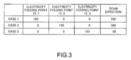
- FIG. 3 shows an operation example of the antenna device.
- the amplitude of each of three electrical signals input to the electricity feeding points is constant.
- the phase of one electrical signal is delayed by 180 degrees compared with those of the other two electrical signals. Specifically, the electrical signal with its phase being delayed by 180 degrees is fed to the electricity feeding point 15-1 in a case 1, the electrical signal with its phase being delayed by 180 degrees is fed to the electricity feeding point 15-2 in a case 2, and the electrical signal with its phase being delayed by 180 degrees is fed to the electricity feeding point 15-3 in a case 3.
- the beam directions show 180 degrees in the case 1, 300 degrees in the case 2, and 60 degrees in the case 3.
- FIG. 4 shows simulation results of the radiation characteristics shown in FIG. 3 on the horizontal plane of the antenna device.
- FIG. 4 shows the radiation characteristics obtained when the center frequency is 2.3 GHz, a radius r1 of the antenna element 11 is 18 mm, a radius r2 of the cylindrical conductor 14 is 4 mm, a thickness h of the antenna main body 1 is 4 mm, and the dielectric constant of the dielectric layer 13 is 2.2.
- Those characteristics indicate that the antenna device according to the exemplary embodiment of the present invention can operate as a sector antenna having three sectors.
- the feeder circuit 2 can switch the phase of an electrical signal according to at least one of the reception sensitivity, the signal quality, and the error rate of the signal received by the antenna device.
- the control section (not shown) monitors the reception sensitivity, the signal quality, and the error rate, controls the switches 23-1, 23-2, and 23-3 to improve those characteristics, and switches the phase of the electric signal to thereby obtain the optimal directivity. Such operations can improve the reception sensitivity and eliminate interferences caused by other terminals.
- a transmission characteristic for example, a transmission power
- the directivity can be finely changed.
- the antenna main body may have any other shape besides a disc shape.
- the antenna device of the present invention can be applied to antennas to be provided for known cellular telephones, radio communication apparatuses for wireless local area networks, and communication apparatuses for radio frequency identification.
- the above radio communication apparatuses each have a control section 30 and a transmission and reception section 31 in addition to the above-described antenna main body 1 and feeder circuit 2, as illustrated in FIG. 5.
Landscapes
- Engineering & Computer Science (AREA)
- Computer Networks & Wireless Communication (AREA)
- Variable-Direction Aerials And Aerial Arrays (AREA)
- Waveguide Aerials (AREA)
Abstract
Description
- The present invention relates to an antenna device, and more particularly to an antenna device capable of controlling its directivity, and a radio communication apparatus using the antenna device.
- Most mobile communication terminals use a nondirectional antenna as an antenna device, because the direction toward a base station to be communicated with always changes. Meanwhile, in recent years, cellular phones, as an example of mobile communication terminals, have come to have a large number of functions. Those functions include website browsing, video telephone, photographing still images or moving images, navigation using the global positioning system, and authentication and checkout using a radio frequency identification technique. In order to implement such various functions, excellent antenna characteristics must be maintained irrespective of the use states of the cellular phones.
- Known as antennas for improving antenna characteristics are diversity antennas, array antennas, Yagi-Uda antennas, patch antennas, and the like. In particular, as disclosed in JP 2000-312112A, a single patch antenna can form a desired radiation area. The patch antenna has a first electricity feeding point and a second electricity feeding point on an X-axis and a Y-axis, respectively, the X-axis and the Y-axis being orthogonal to each other on a conductor patch. Electrical signals fed to these electricity feeding points are different in at least one of amplitude and phase. The patch antenna resonates in directions parallel to the X-axis and also parallel to the Y-axis. As a result, the radio wave of a radio signal, which includes two types of linear polarization orthogonal to each other having the same resonance frequency, is radiated in a Z-axis direction which is opposite to a grounded conductor.
- Inthepatchantenna,Verticalpolarization and horizontal polarization are always orthogonal to each other, and the direction of the directivity is always in the vertical direction (z-axis direction). Accordingly, in the patch antenna, only the polarization planes change, and the direction of the directivity does not change. In the case of patch antenna, plural patch antennas are arranged in an array in order to incline the direction of the directivity from the vertical direction to the horizontal direction. It is difficult to change the direction of the directivity with the use of only a single patch antenna.
- On the other hand, a compact patch antenna having one electricity feeding point is disclosed in the following document: "Compact WLAN Disc Antennas" written by Neil J. McEwan, Raed A. Abd-Alhameed, Embarak M. Ibrahim, Peter S. Excell, and Nazar T. Ali, IEEE transactions on antennas and propagation, vol. 50, No. 12, December 2002. It is also difficult for this antenna to change the directivity.
- An object of the present invention is to provide an antenna device, which is capable of controlling its directivity, and is small in size, and a radio communication apparatus having the antenna device.
- The antenna device includes an antenna main body having at least three electricity feeding points and a feeder circuit for feeding an electrical signal to the antenna main body. The feeder circuit feeds electrical signals different in at least one of amplitude and phase to the electricity feeding points. A radio communication apparatus has a transmission and reception section, an antenna device. The antenna device includes the antenna main body having at least three electricity feeding points and the feeder circuit for feeding an electrical signal to the antenna main body. The feeder circuit feeds electrical signals different in at least one of amplitude and phase to the electricity feeding points.
- In the invention, it is possible to control the directivity with the use of a single antenna. Further, the use of a single antenna allows the antenna device to be so small that the antenna device can be built in cellular phones or the like. Furthermore, it is possible to optimally set the directivity according to communication states.
- The above and other objects, features and advantages of the present invention will become apparent from the following detailed description when taken with the accompanying drawings in which:
- FIGS. 1A and 1B are a plan view and a cross sectional view, respectively, showing an antenna main body according to an embodiment of the present invention;
- FIG. 2 shows a feeder circuit according to the embodiment of the present invention;
- FIG. 3 shows an operation example of an antenna device according to the embodiment of the present invention;
- FIG. 4 shows radiation characteristics of the antenna device according to the embodiment of the present invention; and
- FIG. 5 is a block diagramof a radio communication apparatus according to the embodiment of the present invention.
- Hereinafter, a preferred exemplary embodiment of the present invention will be described. An antenna device according to the example of the present invention includes an antenna
main body 1 having plural layers, and afeeder circuit 2 for feeding an electrical signal to the antennamain body 1. Referring to FIGS. 1A and 1B, the antennamain body 1 has anantenna element 11 serving as an upper layer, aground layer 12 serving as a lower layer, and adielectric layer 13 disposed between the upper layer and the lower layer. Disposed on theantenna element 11 are three electricity feeding points 15-1, 15-2, and 15-3. The antennamain body 1 is a patch antenna having a planar inverted-F antennas structure. The antennamain body 1 further includes: acylindrical conductor 14, namely, a center post, for connecting a center part of theantenna element 11 to a center part of theground layer 12; and three feeder conductors 16-1, 16-2, and 16-3 which are respectively provided for the electricity feeding points 15-1, 15-2, and 15-3 and connected to theantenna element 11. As shown in FIG. 1A, the antennamain body 1 has a disc shape. The feeder conductors 16-1, 16-2, and 16-3 are not connected to theground layer 12. The electricity feeding points 15-1, 15-2, and 15-3 are respectively supplied with electrical signals which are different in at least one of amplitude and phase. Theground layer 12 includes end portions for the feeder conductors, an outer ring-like portion, and a center circular portion. - The three electricity feeding points are preferably arranged at regular intervals on the circumference of a concentric circle of the
circular antenna element 11. Four or more electricity feeding points can be provided. The electricity feeding points may not be arranged at regular intervals. When four or more electricity feeding points are provided, they are not necessarily arranged on an identical circle. - FIG. 2 shows the
feeder circuit 2 according to this example. Thefeeder circuit 2 includes: a dividingconductor 21 for dividing an input electrical signal into three electrical signals to be transferred to electricity feeding points; strip lines 22-1, 22-2, and 22-3 for transferring the divided electrical signals to the three electricity feeding points, respectively; and phase switches 23-1, 23-2, and 23-3 for switching the phases of the electrical signals. The phase switches switch between afirst path 31 and asecond path 32. In this exemplary embodiment, for example, an electrical signal passing through thesecond path 32 has a phase delay of 180 degrees. However, the second path may cause different phase delays. As the phase switches, for example, single pole dual throw (SPDT) switches can be used. The phase switches are controlled by a control section (not shown). - FIG. 3 shows an operation example of the antenna device. In this operation example, the amplitude of each of three electrical signals input to the electricity feeding points is constant. Further, the phase of one electrical signal is delayed by 180 degrees compared with those of the other two electrical signals. Specifically, the electrical signal with its phase being delayed by 180 degrees is fed to the electricity feeding point 15-1 in a
case 1, the electrical signal with its phase being delayed by 180 degrees is fed to the electricity feeding point 15-2 in acase 2, and the electrical signal with its phase being delayed by 180 degrees is fed to the electricity feeding point 15-3 in acase 3. As a result, the beam directions show 180 degrees in thecase case case 3. - FIG. 4 shows simulation results of the radiation characteristics shown in FIG. 3 on the horizontal plane of the antenna device. FIG. 4 shows the radiation characteristics obtained when the center frequency is 2.3 GHz, a radius r1 of the
antenna element 11 is 18 mm, a radius r2 of thecylindrical conductor 14 is 4 mm, a thickness h of the antennamain body 1 is 4 mm, and the dielectric constant of thedielectric layer 13 is 2.2. Those characteristics indicate that the antenna device according to the exemplary embodiment of the present invention can operate as a sector antenna having three sectors. - The
feeder circuit 2 can switch the phase of an electrical signal according to at least one of the reception sensitivity, the signal quality, and the error rate of the signal received by the antenna device. To be more specific, the control section (not shown) monitors the reception sensitivity, the signal quality, and the error rate, controls the switches 23-1, 23-2, and 23-3 to improve those characteristics, and switches the phase of the electric signal to thereby obtain the optimal directivity. Such operations can improve the reception sensitivity and eliminate interferences caused by other terminals. When a terminal having the above-mentioned antenna device is a transceiver, a transmission characteristic (for example, a transmission power) corresponding to the reception characteristic of the antenna device can be obtained, and thus the transmission and reception characteristics are improved. - When an amount of the phase delay is set to be smaller than 180 degrees, the directivity can be finely changed. On the other hand, it is possible to change the amplitude of an electric signal while keeping the phases of the respective electrical signals constant. If many electricity feeding points are provided on an identical circle on the antenna element, the antenna main body may have any other shape besides a disc shape.
- The antenna device of the present invention can be applied to antennas to be provided for known cellular telephones, radio communication apparatuses for wireless local area networks, and communication apparatuses for radio frequency identification. The above radio communication apparatuses each have a
control section 30 and a transmission andreception section 31 in addition to the above-described antennamain body 1 andfeeder circuit 2, as illustrated in FIG. 5. - While the present invention has been described in connection with certain preferred embodiments, it is to be understood that the subject matter encompassed by the present invention is not limited to those specific embodiments. On the contrary, it is intended to include all alternatives, modifications, and equivalents as can be included within the spirit and scope of the following claims.
- Further, it is the inventor's intent to retain all equivalents of the claimed invention even if the claims are amended during prosecution.
Claims (9)
- An antenna device, comprising:an antenna main body having at least three electricity feeding points; anda feeder circuit for feeding an electrical signal to the antenna main body,wherein the feeder circuit feeds electrical signals different in at least one of amplitude and phase to the electricity feeding points.
- An antenna device according to claim 1, wherein the electricity feeding points are arranged on a circumference of an identical circle on the antenna main body.
- An antenna device according to claim 1 or 2, wherein the electricity feeding points are arranged at regular intervals.
- An antenna device according to any of the preceding claims, wherein the antenna main body is formed in a disc shape.
- An antenna device according to claim 4, wherein the electricity feeding points are arranged on a circumference of a circle having the same center as the disc-shaped antenna main body.
- An antenna device according to any of the preceding claims, wherein the antenna main body includes an antenna layer, a dielectric layer, a ground layer, a cylindrical conductor for connecting a center part of the antenna layer to a center part of the ground layer, and conductors connected to the antenna layer at the electricity feeding points.
- An antenna device according to any of the preceding claims, wherein the feeder circuit includes at least one of an amplifier, an attenuator, and a phase switching device.
- An antenna device according to claim 7, wherein the phase switching device switches one of an amplitude and a phase of an electrical signal according to one of a reception sensitivity, a signal quality, and an error rate thereof.
- A radio communication apparatus, comprising:a transmission and reception section; andan antenna device according to any of the preceding claims.
Applications Claiming Priority (1)
| Application Number | Priority Date | Filing Date | Title |
|---|---|---|---|
| JP2004338265A JP2006148728A (en) | 2004-11-24 | 2004-11-24 | Antenna system and radio communication apparatus using the same |
Publications (1)
| Publication Number | Publication Date |
|---|---|
| EP1662608A1 true EP1662608A1 (en) | 2006-05-31 |
Family
ID=35849586
Family Applications (1)
| Application Number | Title | Priority Date | Filing Date |
|---|---|---|---|
| EP05110875A Withdrawn EP1662608A1 (en) | 2004-11-24 | 2005-11-17 | Antenna device and radio communication apparatus |
Country Status (4)
| Country | Link |
|---|---|
| US (1) | US7372426B2 (en) |
| EP (1) | EP1662608A1 (en) |
| JP (1) | JP2006148728A (en) |
| CN (1) | CN1780055A (en) |
Cited By (2)
| Publication number | Priority date | Publication date | Assignee | Title |
|---|---|---|---|---|
| EP2081253A1 (en) * | 2008-01-18 | 2009-07-22 | Laird Technologies AB | Antenna device and portable radio communication device comprising such an antenna device |
| WO2015181510A1 (en) * | 2014-05-28 | 2015-12-03 | Kabushiki Kaisha Toshiba | Antenna |
Families Citing this family (10)
| Publication number | Priority date | Publication date | Assignee | Title |
|---|---|---|---|---|
| WO2006118293A1 (en) * | 2005-04-27 | 2006-11-09 | Semiconductor Energy Laboratory Co., Ltd. | Wireless chip |
| WO2007090065A2 (en) * | 2006-01-27 | 2007-08-09 | Airgain, Inc. | U-antenna |
| WO2008105837A2 (en) * | 2006-09-21 | 2008-09-04 | Noninvasive Medical Technologies, Inc. | Method of processing thoracic reflected radio interrogation signals |
| AU2007297622A1 (en) * | 2006-09-21 | 2008-03-27 | Noninvasive Medical Technologies, Inc. | Antenna for thoracic radio interrogation |
| US8111152B2 (en) * | 2006-09-21 | 2012-02-07 | Noninvasive Medical Technologies, Inc. | Relative positioning system and method |
| US8730114B2 (en) * | 2010-06-02 | 2014-05-20 | Mitre Corporation | Low-profile multiple-beam lens antenna |
| CN104659493A (en) * | 2015-03-10 | 2015-05-27 | 上海艺时网络科技有限公司 | Metal ring-slot antenna and wireless terminal |
| CN108493575B (en) * | 2018-03-12 | 2020-08-04 | Oppo广东移动通信有限公司 | Antenna components and electronic equipment |
| CN110581338B (en) * | 2019-08-15 | 2020-12-29 | 武汉慧联无限科技有限公司 | Gateway equipment is with antenna that has heat dissipation function |
| WO2023034387A1 (en) | 2021-08-31 | 2023-03-09 | SeeMedX, Inc. | Bio electric impedance monitors, electrode arrays and method of use |
Citations (3)
| Publication number | Priority date | Publication date | Assignee | Title |
|---|---|---|---|---|
| US4538153A (en) * | 1981-09-07 | 1985-08-27 | Nippon Telegraph & Telephone Public Corp. | Directivity diversity communication system with microstrip antenna |
| US5714961A (en) * | 1993-07-01 | 1998-02-03 | Commonwealth Scientific And Industrial Research Organisation | Planar antenna directional in azimuth and/or elevation |
| US6252553B1 (en) * | 2000-01-05 | 2001-06-26 | The Mitre Corporation | Multi-mode patch antenna system and method of forming and steering a spatial null |
Family Cites Families (6)
| Publication number | Priority date | Publication date | Assignee | Title |
|---|---|---|---|---|
| JP3020777B2 (en) * | 1993-07-23 | 2000-03-15 | 宏之 新井 | Dual frequency antenna |
| US5880694A (en) * | 1997-06-18 | 1999-03-09 | Hughes Electronics Corporation | Planar low profile, wideband, wide-scan phased array antenna using a stacked-disc radiator |
| JP2000312112A (en) | 1998-09-22 | 2000-11-07 | Matsushita Electric Ind Co Ltd | Patch antenna device |
| JP2004235674A (en) * | 2000-10-17 | 2004-08-19 | Sanyo Electric Co Ltd | Apparatus and method for transmission weight control and radio base station |
| JP2004297590A (en) * | 2003-03-27 | 2004-10-21 | Fujitsu Ltd | Mobile wireless communication device |
| US6933907B2 (en) * | 2003-04-02 | 2005-08-23 | Dx Antenna Company, Limited | Variable directivity antenna and variable directivity antenna system using such antennas |
-
2004
- 2004-11-24 JP JP2004338265A patent/JP2006148728A/en active Pending
-
2005
- 2005-11-17 EP EP05110875A patent/EP1662608A1/en not_active Withdrawn
- 2005-11-22 US US11/283,698 patent/US7372426B2/en not_active Expired - Fee Related
- 2005-11-23 CN CNA2005101150524A patent/CN1780055A/en active Pending
Patent Citations (3)
| Publication number | Priority date | Publication date | Assignee | Title |
|---|---|---|---|---|
| US4538153A (en) * | 1981-09-07 | 1985-08-27 | Nippon Telegraph & Telephone Public Corp. | Directivity diversity communication system with microstrip antenna |
| US5714961A (en) * | 1993-07-01 | 1998-02-03 | Commonwealth Scientific And Industrial Research Organisation | Planar antenna directional in azimuth and/or elevation |
| US6252553B1 (en) * | 2000-01-05 | 2001-06-26 | The Mitre Corporation | Multi-mode patch antenna system and method of forming and steering a spatial null |
Non-Patent Citations (1)
| Title |
|---|
| MCEWAN N J ET AL: "COMPACT WLAN DISC ANTENNAS", IEEE TRANSACTIONS ON ANTENNAS AND PROPAGATION, IEEE SERVICE CENTER, PISCATAWAY, NJ, US, vol. 50, no. 12, December 2002 (2002-12-01), pages 1862 - 1864, XP001143599, ISSN: 0018-926X * |
Cited By (2)
| Publication number | Priority date | Publication date | Assignee | Title |
|---|---|---|---|---|
| EP2081253A1 (en) * | 2008-01-18 | 2009-07-22 | Laird Technologies AB | Antenna device and portable radio communication device comprising such an antenna device |
| WO2015181510A1 (en) * | 2014-05-28 | 2015-12-03 | Kabushiki Kaisha Toshiba | Antenna |
Also Published As
| Publication number | Publication date |
|---|---|
| US20060109180A1 (en) | 2006-05-25 |
| US7372426B2 (en) | 2008-05-13 |
| JP2006148728A (en) | 2006-06-08 |
| CN1780055A (en) | 2006-05-31 |
Similar Documents
| Publication | Publication Date | Title |
|---|---|---|
| KR101891447B1 (en) | Wireless charging and communications systems with dual-frequency patch antennas | |
| CN100433453C (en) | Antenna device | |
| US6662028B1 (en) | Multiple frequency inverted-F antennas having multiple switchable feed points and wireless communicators incorporating the same | |
| US7388552B2 (en) | Multibeam antenna | |
| US9887461B2 (en) | Re-configurable built-in antenna for portable terminal | |
| US7602340B2 (en) | Antenna device and wireless terminal using the antenna device | |
| JP3903991B2 (en) | Antenna device | |
| US6700540B2 (en) | Antennas having multiple resonant frequency bands and wireless terminals incorporating the same | |
| US20100214189A1 (en) | Antenna, radiating pattern switching method therefor and wireless communication apparatus | |
| KR20010053422A (en) | Miniature printed spiral antenna for mobile terminals | |
| JP2016523491A (en) | Multiple antenna system and mobile terminal | |
| JPH09260925A (en) | Antenna device | |
| CN105140623A (en) | Antenna system and communication terminal using the antenna system | |
| KR20020027637A (en) | Antenna arrangement and portable radio communication device | |
| CN106450771A (en) | Electronic device and multiband antenna thereof | |
| US7372426B2 (en) | Antenna device and radio communication apparatus | |
| CN101553954B (en) | Antenna subassemblies for electronic devices | |
| US20020101376A1 (en) | Monopole antenna for array applications | |
| US20120162035A1 (en) | All-in-one multi-band antenna for wireless communication system | |
| JP4910868B2 (en) | Antenna device | |
| US10749556B2 (en) | Antenna apparatus and wireless apparatus | |
| JP2006115451A (en) | Directional control microstrip antenna, radio module using the antenna, and radio system | |
| CN120073290A (en) | Communication terminal with interleaved free-standing antenna radiator | |
| EP3376594B1 (en) | Automotive antenna | |
| JP2592128Y2 (en) | Flat antenna |
Legal Events
| Date | Code | Title | Description |
|---|---|---|---|
| PUAI | Public reference made under article 153(3) epc to a published international application that has entered the european phase |
Free format text: ORIGINAL CODE: 0009012 |
|
| AK | Designated contracting states |
Kind code of ref document: A1 Designated state(s): AT BE BG CH CY CZ DE DK EE ES FI FR GB GR HU IE IS IT LI LT LU LV MC NL PL PT RO SE SI SK TR |
|
| AX | Request for extension of the european patent |
Extension state: AL BA HR MK YU |
|
| 17P | Request for examination filed |
Effective date: 20061128 |
|
| AKX | Designation fees paid |
Designated state(s): DE FR GB IT |
|
| 17Q | First examination report despatched |
Effective date: 20070411 |
|
| STAA | Information on the status of an ep patent application or granted ep patent |
Free format text: STATUS: THE APPLICATION IS DEEMED TO BE WITHDRAWN |
|
| 18D | Application deemed to be withdrawn |
Effective date: 20070822 |