EP1662330A1 - Device and method for belt speed control, and image forming apparatus - Google Patents
Device and method for belt speed control, and image forming apparatus Download PDFInfo
- Publication number
- EP1662330A1 EP1662330A1 EP05025495A EP05025495A EP1662330A1 EP 1662330 A1 EP1662330 A1 EP 1662330A1 EP 05025495 A EP05025495 A EP 05025495A EP 05025495 A EP05025495 A EP 05025495A EP 1662330 A1 EP1662330 A1 EP 1662330A1
- Authority
- EP
- European Patent Office
- Prior art keywords
- sensor
- belt
- controlling
- signals
- scale
- Prior art date
- Legal status (The legal status is an assumption and is not a legal conclusion. Google has not performed a legal analysis and makes no representation as to the accuracy of the status listed.)
- Granted
Links
- 238000000034 method Methods 0.000 title claims description 19
- 238000001514 detection method Methods 0.000 claims description 28
- 238000011144 upstream manufacturing Methods 0.000 claims description 14
- 238000012546 transfer Methods 0.000 description 91
- 239000011295 pitch Substances 0.000 description 13
- 230000008569 process Effects 0.000 description 10
- 230000015572 biosynthetic process Effects 0.000 description 4
- 230000015556 catabolic process Effects 0.000 description 4
- 238000006731 degradation reaction Methods 0.000 description 4
- 239000011521 glass Substances 0.000 description 4
- 230000002159 abnormal effect Effects 0.000 description 3
- 230000008859 change Effects 0.000 description 3
- 238000010586 diagram Methods 0.000 description 3
- 230000006870 function Effects 0.000 description 3
- 238000004140 cleaning Methods 0.000 description 2
- 239000003086 colorant Substances 0.000 description 2
- 238000005516 engineering process Methods 0.000 description 2
- 230000003287 optical effect Effects 0.000 description 2
- 230000002441 reversible effect Effects 0.000 description 2
- 230000000630 rising effect Effects 0.000 description 2
- 238000003860 storage Methods 0.000 description 2
- 241000668842 Lepidosaphes gloverii Species 0.000 description 1
- 230000002411 adverse Effects 0.000 description 1
- 238000013459 approach Methods 0.000 description 1
- 239000002131 composite material Substances 0.000 description 1
- 238000010276 construction Methods 0.000 description 1
- 230000007423 decrease Effects 0.000 description 1
- 230000003247 decreasing effect Effects 0.000 description 1
- 230000003111 delayed effect Effects 0.000 description 1
- 238000011161 development Methods 0.000 description 1
- 239000013013 elastic material Substances 0.000 description 1
- 238000003384 imaging method Methods 0.000 description 1
- 238000012986 modification Methods 0.000 description 1
- 230000004048 modification Effects 0.000 description 1
- 239000004033 plastic Substances 0.000 description 1
- 229920005668 polycarbonate resin Polymers 0.000 description 1
- 239000004431 polycarbonate resin Substances 0.000 description 1
- 229920001721 polyimide Polymers 0.000 description 1
- 239000009719 polyimide resin Substances 0.000 description 1
- 238000003825 pressing Methods 0.000 description 1
- 238000012545 processing Methods 0.000 description 1
- 238000010791 quenching Methods 0.000 description 1
- 230000000171 quenching effect Effects 0.000 description 1
- 239000011347 resin Substances 0.000 description 1
- 229920005989 resin Polymers 0.000 description 1
- 238000005096 rolling process Methods 0.000 description 1
- 230000001360 synchronised effect Effects 0.000 description 1
Images





Classifications
-
- G—PHYSICS
- G03—PHOTOGRAPHY; CINEMATOGRAPHY; ANALOGOUS TECHNIQUES USING WAVES OTHER THAN OPTICAL WAVES; ELECTROGRAPHY; HOLOGRAPHY
- G03G—ELECTROGRAPHY; ELECTROPHOTOGRAPHY; MAGNETOGRAPHY
- G03G15/00—Apparatus for electrographic processes using a charge pattern
- G03G15/50—Machine control of apparatus for electrographic processes using a charge pattern, e.g. regulating differents parts of the machine, multimode copiers, microprocessor control
- G03G15/5008—Driving control for rotary photosensitive medium, e.g. speed control, stop position control
-
- G—PHYSICS
- G03—PHOTOGRAPHY; CINEMATOGRAPHY; ANALOGOUS TECHNIQUES USING WAVES OTHER THAN OPTICAL WAVES; ELECTROGRAPHY; HOLOGRAPHY
- G03G—ELECTROGRAPHY; ELECTROPHOTOGRAPHY; MAGNETOGRAPHY
- G03G2215/00—Apparatus for electrophotographic processes
- G03G2215/00025—Machine control, e.g. regulating different parts of the machine
- G03G2215/00071—Machine control, e.g. regulating different parts of the machine by measuring the photoconductor or its environmental characteristics
- G03G2215/00075—Machine control, e.g. regulating different parts of the machine by measuring the photoconductor or its environmental characteristics the characteristic being its speed
-
- G—PHYSICS
- G03—PHOTOGRAPHY; CINEMATOGRAPHY; ANALOGOUS TECHNIQUES USING WAVES OTHER THAN OPTICAL WAVES; ELECTROGRAPHY; HOLOGRAPHY
- G03G—ELECTROGRAPHY; ELECTROPHOTOGRAPHY; MAGNETOGRAPHY
- G03G2215/00—Apparatus for electrophotographic processes
- G03G2215/01—Apparatus for electrophotographic processes for producing multicoloured copies
- G03G2215/0103—Plural electrographic recording members
- G03G2215/0119—Linear arrangement adjacent plural transfer points
Definitions
- the present invention relates to a technology for controlling speed of an endless belt by a feedback control performed based on detection of scale marks formed on the belt.
- An image forming apparatus generally includes a belt-speed control device that controls the speed of an intermediate transfer belt.
- a plastic scale seal with scale marks is adhered to the periphery of the intermediate transfer belt.
- a sensor (reflective photosensor) reads the scale marks and outputs detection pulses. Based on the detection pulses, the speed of the intermediate transfer belt is controlled by controlling a belt driving motor that drives the intermediate transfer belt. Thus, the speed of the intermediate transfer belt can be stabilized at an ideal speed.
- One approach is to control the belt speed by a dummy pulse stored in a RAM, etc., instead of using the pulse output by the sensor when the gap passes under the sensor.
- the average interval of the dummy pulses is the same as that of the pulses output by the sensor when reading the scale marks while the intermediate transfer belt is being driven at an ideal speed.
- the belt can be driven at an ideal speed even when the gap is encountering the sensor.
- the control system controls the belt speed by using the dummy pulse.
- the control system might continue using the detection pulse output from the sensor during the delay period and perform feedback control of the belt speed based on the detection pulses.
- the belt speed is erroneously increased before employing the dummy pulse. As a result, the belt speed cannot be accurately controlled.
- the sensor generally cannot immediately detect the gap when the front end of the scale reaches the sensor. The reason for this is because of the characteristic of an analog voltage output that is output by the sensor upon reading the scale marks of the scale.
- Fig. 13 depicts the characteristic of the analog voltage output that is output by the sensor upon reading the scale marks of the scale.
- An output voltage value ⁇ represents the output voltage value when the sensor is reading the scale marks. As the gap reaches the sensor, the voltage gradually drops. When the output voltage drops to a threshold ⁇ or less, the control system recognizes that the gap region has begun from this point on, and switches to controlling the belt speed based on the dummy pulses instead of the detection pulses.
- the control system does not implement control using the dummy pulse even though the actual gap region has crossed the sensor. Consequently, the belt speed is controlled inaccurately, resulting in misaligned toner images and leading to degradation of color image.
- a belt-speed control device having two sensors.
- a first sensor provided upstream in the direction in which the belt is driven, detects the gap
- a second sensor provided downstream in the direction in which the belt is driven, controls the belt speed.
- the second sensor takes over the control only after the first sensor recognizes the gap, resulting in the delay as denoted by "x" in Fig. 13. Therefore, the problem remains unsolved.
- Japanese Patent Laid-Open Publication No. 2004-69933 discloses two examples of another belt-speed control device.
- the surface of an endless belt is covered with a linear scale (scale seal) having a plurality of timing scale marks (pitches) along the circumferential direction.
- Three sensors with spaces therebetween in the circumferential direction are provided along the linear scale.
- Two of the sensors simultaneously read the linear scale and each sensor outputs a signal.
- a linear encoder receives the signals from both the sensors and synchronizes the pulse timings of the pulse signals of the two sensors.
- a controller controls the belt speed based on the signal output from the linear encoder.
- two linear scales forming two columns in the breadth direction of the endless belt are provided at shifted positions in the circumferential direction of the belt in such a manner that their edges overlap with each other.
- Two sensors are arranged so that each sensor reads one of the linear scales.
- controlling the speed requires complex software to synchronize the timings of the pulse signals output by the two sensors.
- the belt must be wide enough to accommodate two linear scales, which makes the scale of the device bigger. Further, arranging the two linear scales perfectly parallel to each other is a difficult task.
- a device for controlling speed of a belt wherein a scale including a plurality of equally spaced marks is attached to the belt in a direction of movement of the belt such that a gap is formed between a first end and a second end of the scale includes a first sensor configured to detect the marks on the scale and output a first signal upon detecting a mark among the marks, a second sensor configured to detect the marks on the scale and output a second signal upon detecting a mark among the marks, wherein the first sensor and the second sensor are located at different positions along the direction, and a controlling unit that controls the speed based on any one of the first signals and the second signals according to a position of the gap detected by the first sensor and the second sensor.
- a device for controlling speed of a belt wherein a scale including a plurality of equally spaced marks is attached to the belt in a direction of movement of the belt such that a gap is formed between a first end and a second end of the scale includes a plurality of sensors configured to detect the marks on the scale and output signals upon detecting the marks, a first sensor among the plurality of sensors that outputs a first signal upon detecting a mark among the marks, a second sensor among the plurality of sensors that outputs a second signal upon detecting a mark among the marks, wherein the first sensor and the second sensor are located at different positions along the direction, and a controlling unit that controls the speed based on any one of the first signals and the second signals according to a position of the gap detected by the first sensor and the second sensor.
- an image forming apparatus includes an image forming unit that forms images by movement of a belt, wherein a scale including a plurality of equally spaced marks is attached to the belt in a direction of movement of the belt such that a gap is formed between a first end and a second end of the scale, and a device that controls speed of the belt, including a first sensor configured to detect the marks on the scale and output a first signal upon detecting a mark among the marks, a second sensor configured to detect the marks on the scale and output a second signal upon detecting a mark among the marks, wherein the first sensor and the second sensor are located at different positions along the direction, and a controlling unit that controls the speed based on any one of the first signals and the second signals according to a position of the gap detected by the first sensor and the second sensor.
- a method for controlling speed of a belt wherein a scale including a plurality of equally spaced marks is attached to the belt in a direction of movement of the belt such that a gap is formed between a first end and a second end of the scale includes detecting the marks on the scale at a first position, detecting the marks on the scale at a second position, wherein the first position and the second position are located at different positions along the direction, and controlling the speed based on detection results at any one of the first position and the second position according to a position of the gap detected at any one of the first position and the second position.
- a device for controlling speed of a belt wherein a scale including a plurality of equally spaced marks is attached to the belt in a direction of movement of the belt such that a gap is formed between a first end and a second end of the scale includes first detecting means for detecting the marks on the scale and outputting a first signal upon detecting a mark among the marks, second detecting means for detecting the marks on the scale and outputting a second signal upon detecting a mark among the marks, wherein the first detecting means and the second detecting means are located at different positions along the direction, and controlling means for controlling the speed based on any one of the first signals and the second signals according to a position of the gap detected by the first detecting means and the second detecting means.
- Fig. 1 is a schematic diagram of a belt-speed control device of an image forming apparatus according to an embodiment of the present invention.
- Fig. 2 depicts an overall structure of the image forming apparatus according the embodiment.
- Fig. 3 is a top view of the belt-speed control device including two sensors that read scale marks provided on an intermediate transfer belt.
- a color copier is presented as an example of the image forming apparatus.
- the color copier is a tandem image forming apparatus and includes four drum-type photosensitive members (hereinafter, "photosensitive member 40" unless otherwise specified), 40Y, 40C, 40M, and 40K for the four colors yellow (Y), cyan (C), magenta (M), and black (K) and an intermediate transfer belt 10 on which the image formed on each of the photosensitive members gets transferred at each first transfer position where a roller-type primary transfer device 62 is located.
- photosensitive member 40 drum-type photosensitive members
- the belt-speed control device of the image forming apparatus includes a scale 5 (only a portion of it is shown in Fig. 1) having a plurality of scale marks 5a and a seam 11 in the circumferential direction.
- the scale is bonded to the entire surface of the intermediate transfer belt 10, as shown in Fig. 3.
- a sensor 6A and a sensor 6B read the scale marks 5a of the scale 5 and each of the sensors 6A and 6B outputs an output value.
- a controller 70 shown in Fig. 1 that functions as a control unit receives the output value and performs feedback control based on the output value to drive the intermediate transfer belt 10 at a uniform speed.
- Feedback control involves detecting of the actual speed of the intermediate transfer belt 10 by the sensor 6A and the sensor 6B by reading the scale marks 5a of the scale 5, and decreasing or increasing the actual speed of the intermediate transfer belt (hereinafter, "belt speed”) to the target speed depending on the actual speed.
- the sensor 6A is a primary sensor and the sensor 6B is a secondary sensor.
- the sensor 6B is located upstream of the sensor 6A in the direction in which the intermediate transfer belt 10 is driven.
- the belt-speed control device includes a sensor switching unit (provided in the controller 70 in the embodiment).
- the sensor switching unit switches over feedback control from the sensor 6A to the sensor 6B in the period spanning from the moment a rear end 11b of the seam 11 shown in Fig. 3 crosses the detection position of the sensor 6B (the secondary sensor) up until just before sensor A (the primary sensor) encounters the seam 11.
- the color image forming apparatus shown in Fig. 2 has a copier main unit 1 set on a paper feeding table 2.
- a scanner 3 and an automatic document feeder (ADF) 4 are mounted on the copier main unit 1.
- the copier main unit 1 includes a transfer device 20 in its mid portion.
- the transfer device 20 includes the intermediate transfer belt 10.
- the intermediate transfer belt 10 is stretched over a driving roller 9 and two driven rollers 15 and 16 and is driven in a clockwise direction in Fig. 2.
- a belt cleaning device 17 located to the left of the driven roller 15 removes a residual toner remaining after image transfer from the surface of the intermediate transfer belt 10.
- the four photosensitive members 40 are located along the direction of movement of the intermediate transfer belt 10 above the straight portion of the intermediate transfer belt 10 stretched between the driving roller 9 and the driven roller 15. Each of the photosensitive members 40 turns in a counter-clockwise direction. The image (toner image) formed on each of the photosensitive members 40 is superposed sequentially on the intermediate transfer belt 10.
- each photosensitive member 40 Around each photosensitive member 40 are provided a charging device 60, a developing device 61, the primary transfer device 62, a photosensitive member cleaning device 63, and a quenching device 64.
- An exposing device 21 is provided above the photosensitive member 40.
- the secondary transfer device 22 includes a secondary transfer belt 24, which is an endless belt, stretched across two rollers 23 and 23.
- the secondary transfer belt 24 presses against the secondary roller 16 with the intermediate transfer belt 10 disposed between them.
- the secondary transfer device 22 transfers the toner images at once from the intermediate transfer belt 10 to the sheet P that is conveyed between the secondary transfer belt 24 and the intermediate transfer belt 10.
- a fixing device 25 is located downstream of the sheet conveyance direction with respect to the secondary transfer device 22.
- the fixing device 25 includes a fixing belt 26, which is an endless belt, and a pressure roller 27 pressed against the fixing belt 26.
- the secondary transfer device 22 also performs the function of conveying the sheet P with the image formed thereon to the fixing device 25.
- a transfer roller or a non-contact charger can also be used as the secondary transfer device 22.
- a sheet flipping device 28 that flips the sheet P when images are to be recorded on both sides of the sheet P is located below the secondary transfer device 22.
- an original When taking a color copy using the color copier, an original is normally placed on a document dispenser 30 of the automatic document feeder 4. However, the original can be placed manually after opening the automatic document feeder 4 and placing the original on a contact glass 32 of the scanner 3 and pressing the original against the contact glass 32 by closing the automatic document feeder 4.
- the original placed on the automatic document feeder 4 is automatically carried to the contact glass 32. If the original is manually placed on the contact glass 32, operating the switch starts a first scanning member 33 and a second scanning member 34 of the scanner 3. A beam from the light source of the first scanning member 33 exposes the original. The light reflected from the original is directed by a mirror of the first scanning member towards the second scanning member. This light hits a pair of mirrors of the second scanning member 34 and flips 180° upon hitting the mirrors. This reflected light then passes through an imaging lens 35 and enters a reading sensor 36 that reads the content of the original.
- the intermediate transfer belt 10 As well as the photosensitive members 40Y, 40C, 40M, and 40K start turning. Yellow, cyan, magenta, and black images are respectively formed on the photosensitive members 40Y, 40C, 40M, and 40K.
- the images of each color formed on the photosensitive members 40 are superposed on the intermediate transfer belt 10 that is driven clockwise in Fig. 2 and form a composite full color image.
- a feeding roller 42 of the feeding rung selected from a paper feeding table 2 turns and the sheet P from a selected feeding cassette 44 in a paper bank 43 is rolled out and separated into single sheets by a separating roller 45, and conveyed to a feeding channel 48.
- the sheet P comes in contact with a resist roller 49 and comes to a stop for a while.
- the sheets P placed in a manual tray 51 are rolled out by a rolling feeding roller 50, separated into single sheets by a separating roller 52, and conveyed to a manual feeding channel 53.
- the sheet P then comes to a stop upon contact with the resist roller 49.
- the resist roller 49 starts turning synchronous with the color image on the intermediate transfer belt 10 and conveys the sheet P that has come to a halt between the intermediate transfer belt 10 and the secondary transfer device 22 and causes the color image to be transferred to the sheet P by the secondary transfer device 22.
- the sheet P bearing the color image is conveyed by the secondary transfer device 22 to the fixing device 25.
- the fixing device 25 fixes the color image by application of heat and pressure.
- the sheet P bearing a fixed color image is guided towards the exit by a switching pawl 55 and is ejected by an ejection roller 56 and is stacked on a discharge tray 57.
- the sheet P bearing the color image on one side is conveyed to the sheet flipping device 28 by the switching pawl 55.
- the sheet flipping device 28 flips the sheet P and reintroduces the sheet P to the transfer position and allows the image to be formed on the reverse side. Once the image formation on the, reverse side is completed, the sheet P is ejected to the discharge tray 57 by the ejection roller 56.
- the sensor 6A and the sensor 6B are set on the edge at a distance of Lp from each other, respectively in the direction of the belt movement, and read the scale 5 (also see Fig. 4) provided on the entire surface of the intermediate transfer belt 10 (the scale 5 can also be provided on the underside of the intermediate. transfer belt 10).
- the distance Lp is a mechanically set distance at the time of designing and corresponds to the distance from the edge of the sensor 6B where the intermediate transfer belt 10 enters and the edge of the sensor 6A where the intermediate transfer belt 10 emerges. As shown in Fig.
- the controller 70 detects the actual speed of the intermediate transfer belt 10 from the data output by the sensor 6A and the sensor 6B upon reading of the scale marks 5a of the scale 5, and adjusts the actual speed of the intermediate transfer belt 10 to the target speed (standard speed) by controlling a belt driving motor 7.
- the controller 70 includes a micro-computer consisting of a central processing unit (CPU), a read-only memory (ROM), a random access memory (RAM), and an input/output (I/O) circuit.
- the CPU of the micro-computer performs functions related to determining processes and other processes.
- the ROM stores programs and data required for the various processes.
- the RAM is a data memory for storing process data.
- the controller 70 is connected to the sensor 6A and the sensor 6B as well as the belt driving motor 7 so that it can perform feedback control of the belt speed.
- the controller 70 is also connected to the reading sensor 36, the exposing device 21 and an image forming unit 18 so that it can control the optical writing based on a detection result of the reading sensor and formation of the toner images in four colors by development, superposing and intermediate transfer. Apart from these, the controller 70 is connected to load-bearing members such as the driving system, etc.
- the driving system of the intermediate transfer belt 10 and the belt speed detecting system of the intermediate transfer belt 10 are explained next.
- the torque of the belt driving motor 7 stretches and relays the intermediate transfer belt 10 to the driving roller 9 so that the intermediate transfer belt 10 can be driven.
- the intermediate transfer belt 10 is composed of fluoric resin, polycarbonate resin, polyimide resin, etc. All the layers or some of the layers of the intermediate transfer belt 10 can be made of an elastic material.
- the belt driving motor 7 drives the intermediate transfer belt 10 in the direction of the arrow C by turning the driving roller 9.
- the torque can be relayed from the belt driving motor 7 to the driving roller 9 directly or via a gear system.
- the scale 5 is provided on the entire surface of the intermediate transfer belt 10 (in Fig. 3 only the vicinity of the seam 11 is shown).
- the position of the scale 5 in the width direction of the intermediate transfer belt 10 corresponds to the edge of the photosensitive member 40 and falls in the non-image forming area.
- the sensor 6A and the sensor 6B are identical. As shown in Fig. 4, both the sensor 6A and the sensor 6B are reflective optical sensors, each consisting of a pair of photo emitter 6a and photo receiver 6b.
- the photo emitter 6a emits light towards the scale 5 and the photo receiver 6b receives the light reflected from the scale 5.
- the sensor 6A and the sensor 6B detect the difference in the amount of reflected light from the region of the scale 5 having the scale mark 5a and a region 5b having no scale mark.
- the sensor 6A and the sensor 6B output signals having two values, namely High and Low, based on the difference in the reflection rate from the region of the scale 5 having the scale mark 5a and the region 5b having no scale mark.
- the sensor 6A and the sensor 6B output High signal when the photo receiver receives light
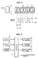
- the range denoted by "t" in Fig. 4 denotes the output when the scale mark 5a has crossed the sensor 6A or the sensor 6B.
- the speed of movement of the intermediate transfer belt 10 (belt speed) can be detected by determining a period T from the instant the signal turns from Low to High to the instant when the signal next turns Low or High.
- Any type of sensor or scale can be used as long as it is possible to detect the belt speed by reading the scale on the intermediate transfer belt 10.
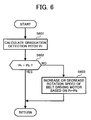
- the controller 70 shown in Fig. 5 performs the basic feedback control of the belt speed by implementing the routine shown in Fig. 6. That is, the controller 70 calculates a graduation detection pitch Pr based on an output voltage value output by the sensor 6A or the sensor 6B (step S601) (the selection of the sensor 6A or the sensor 6B is explained later). The controller 70 performs the calculation by counting the difference between the rising portions of the High voltages (see Fig. 4) or the falling portions of the Low voltages.
- the controller 70 determines whether the graduation detection pitch Pr obtained by calculation is equal to a basic pitch value Pb (T in Fig. 4 in this example) (step S602). If Pr is found to be equal to Pb ("Yes" at step S602), the controller 70 determines that no change has occurred in the belt speed and returns to the main routine. If Pr is found to be not equal to Pb ("No" at step S602), the controller 70 determines that a change has occurred in the belt speed and increases or decreases the rotation speed of the belt driving motor 7 by the ratio corresponding to the value "Pr-Pb" (step S603).
- the color image forming apparatus prevents any variation in the belt speed by performing feedback control of the belt driving motor 7 based on the result obtained by comparing the graduation detection pitch Pr and the basic pitch value Pb.
- the controller 70 speeds up the belt driving motor 7 by the ratio corresponding to the obtained value. Conversely, if the value of "Pr-Pb is negative, the controller 70 slows down the belt driving motor 7 by the ratio corresponding to the obtained value.
- the controller 70 entirely performs feedback control of the intermediate transfer belt 10, thus preventing variation in the belt speed and the resulting image degradation due to shifted superposition of the toner images.
- a gap S shown in Fig. 3 can be formed at the seam 11 between one end (front end 11a) of the seam 11 and the other end (rear end 11b) of the seam 11.
- the graduation detection pitch Pr which corresponds to a length L3 obtained by adding a length L1 of the scale mark 5a and a length L2 of the region 5b having no scale mark, becomes Pr' at the seam 11, which is obtained by adding the length of the gap S to the graduation detection pitch Pr.
- the pitch between the scale mark 5a' and the scale mark 5a" changes from the normal graduation detection pitch Pr to Pr', forming an abnormal pitch region, even if the belt speed has not changed.
- the controller 70 When encountering the abnormal pitch region at the seam 11, the controller 70 mistakenly determines that the belt speed has fallen and performs feedback control, speeding up the belt. Consequently, the superposition of the toner images transferred to the intermediate transfer belt 10 is shifted leading to color inconsistency in the image.
- the color image forming apparatus by providing two sensors, the sensor 6A and the sensor 6B, and switching over the control of belt speed from the sensor 6A to the sensor 6B in the period spanning from the moment the rear end of the seam 11 crosses the detection position of the sensor 6B up until just before the sensor 6A encounters the seam 11, uniform belt speed is maintained even when the seam 11 is encountered. Consequently, shift in the superposition of the toner images and the resulting image degradation due to color inconsistency can be prevented.
- the distance Lp between the sensor 6A and the sensor 6B is a mechanically set distance at the time of designing.
- the sensor 6A and the sensor 6B need not be two separate entities, as shown in Fig. 3, but can be integrated into a single unit.
- Fig. 8 is a top view of two sensors integrated into a single unit. Integrating two sensors into a single unit as shown in Fig. 8 helps avoid shifting of the sensors over long periods of use and maintain a constant distance Lp between the sensors. As a result, the control is switched between the sensors without delay and a uniform speed of the intermediate transfer belt 10 can be maintained.
- Fig. 7 is a flow chart of the belt speed feedback control routine performed by implementing the belt speed control method involving switching the control of the speed belt between the two sensors.
- the controller 70 assigns control of belt speed to the sensor 6A and uses the output value of the sensor 6A to perform feedback control (step S701).
- the controller 70 performs the belt speed control (the basic feedback control of belt speed) explained with reference to Fig. 6 based on the output value of the sensor 6A (step S702).
- the controller 70 determines whether the sensor 6B has encountered the seam 11, that is, whether the rear end 11b of the seam 11 has crossed the detection position of the sensor 6B (step S703). If it is determined that the rear end 11b has not crossed the sensor 6B ("No" at step S703), the process returns to step S701.
- the controller 70 determines whether it is time to switch over the control of the belt speed to the sensor 6B (step S704).
- the switching time spans from the instant the rear end 11b of the seam 11 crosses the detection position of the sensor 6B up until just before the sensor 6A encounters the seam 11. More specifically, the switching time corresponds to a period spanning from the time the length of the intermediate transfer belt 10 corresponding to the gap S of the seam 11 crosses the sensor 6B after the sensor 6B encounters the front end 11a of the seam 11 on the intermediate transfer belt 10 up until just before the length of the intermediate transfer belt 10 corresponding to the gap S of the seam 11 traverses the distance Lp (more accurately, the distance obtained after deducting the width of the sensor 6A from the distance Lp) between the sensor 6B and the sensor 6A after the sensor 6B encounters the front end 11a of the seam 11 on the intermediate transfer belt 10.
- the time taken by the intermediate transfer belt 10 to traverse the distance Lp is 70 ms, and that there are ten scale marks 5a in the distance Lp, it can be surmised that it takes 7 ms for the intermediate transfer belt 10 to traverse the distance corresponding to one scale mark 5a.
- the controller 70 switches over the control from the sensor 6A to the sensor 6B after 60 ms have elapsed, that is, 3 ms before the intermediate transfer belt 10 traverses the distance corresponding to nine scale marks 5a.
- the controller 70 determines the time required for the seam 11 to traverse the pre-stored distance Lp between the sensor 6B and the sensor 6A and sets, as the switching time, the time immediately before the seam 11 reaches the sensor 6A.
- the controller 70 repeats the process until it is time to switch over the control. If it is determined that it is time to switch over the control to the sensor 6B ("Yes” at step S704), the controller 70 assigns control of the speed belt to the sensor 6B and uses the output value of the sensor 6B for performing feedback control of the belt speed (step S705). The controller 70 performs the belt speed control (the basic feedback control of belt speed) explained with reference to Fig. 6 based on the output value of the sensor 6B (step S706).
- the controller 70 determines whether the seam 11 has completely crossed the detection position of the sensor 6A (step S707).
- the seam 11 completely crossing the detection position of the sensor 6A indicates that the intermediate transfer belt 10 has traversed a distance which is greater than the distance obtained by adding the gap S at the seam 11 to the distance Lp, which is the distance between the sensor 6A and the sensor 6B, after the sensor B detects the front end 11a of the seam 11 on the intermediate transfer belt 10.
- step S707 If it is determined that the seam 11 has not completely crossed the detection position of the sensor 6A ("No" at step S707), the process returns to step S705. If it is determined that the seam 11 has completely crossed the sensor 6A ("Yes” at step S707), the controller 70 determines whether a stop belt signal has been input (step S708).
- the stop belt signal is a signal that stops the intermediate transfer belt 10. If it is determined that no stop belt signal has been input (“No” at step S708), the process returns to step S701 as the image forming operation continues uninterrupted, where the controller 70 reassigns control of the belt speed to the sensor 6A, and performs feedback control of the belt speed based on the output value of the sensor 6A. The subsequent steps are repeated.
- the belt speed can be controlled accurately with a software that helps maintain a uniform belt speed based on the signal from the sensors.
- a software that helps maintain a uniform belt speed based on the signal from the sensors.
- control of belt speed can also be switched over from the sensor 6B back to the sensor 6A when the sensor 6A detects input of a normal detection signal (a signal from the region having the equidistant scale marks 5a) .
- the control of the belt speed can be switched from the sensor 6B to the sensor 6A at any timing as long as the seam 11 has completely crossed the sensor 6A, and therefore, there is no need to provide a counter for counting time for this switching. However, the control of the belt speed should be switched back to the sensor A until the seam 11 is detected by the sensor B in the next lap.
- the time just before the seam 11 reaches the sensor A after traversing the pre-stored distance Lp between the sensor 6B and the sensor 6A is set as the time for switching the control of the belt speed from one sensor to the other.
- the belt speed varies, such as when the belt driving motor 7 is started up, the time when the seam 11 is about to cross the sensor 6A or cross past the sensor 6A does not remain constant, thus leading to improper control of belt speed.
- the belt driving motor (driving source that drives the belt) 7 is just started up and its speed tends to vary, it is preferable to halt the intermediate transfer belt 10 in such a way that the seam 11 does not lie between the sensor 6A and the sensor 6B or very close to either the sensor 6A or the sensor 6B. This control is also performed by the controller 70.
- An image forming program executed by the image forming apparatus according to the embodiment can be made readily available on a read-only memory (ROM).
- ROM read-only memory
- the image forming program executed by the image forming apparatus according to the embodiment can be recorded in an installable format on a computer-readable recording medium such as a compact disk-read-only memory (CD-ROM), flexible disk (FD), compact disk - recordable (CD-R), digital versatile disk (DVD), etc.
- a computer-readable recording medium such as a compact disk-read-only memory (CD-ROM), flexible disk (FD), compact disk - recordable (CD-R), digital versatile disk (DVD), etc.
- the image forming program executed by the image forming device according to the embodiment can be stored on a computer connected to a network, such as the Internet, and can be downloaded via the network.
- the image forming program can be provided or distributed via the network.
- the image forming program executed by the image forming apparatus can be in the form of a module that includes the controller 70.
- the CPU reads the image forming program from the ROM and loads the controller 70 to a primary storage device to generate the controller 70 on the primary storage device.
- the present invention has wide application as an image forming apparatus having a belt-speed control device, a program for belt speed control, and a belt speed control method.
- a belt speed can be accurately controlled without requiring complex software, so that misalignment of toner images can be reliably prevented.
Landscapes
- Engineering & Computer Science (AREA)
- Microelectronics & Electronic Packaging (AREA)
- Physics & Mathematics (AREA)
- General Physics & Mathematics (AREA)
- Electrostatic Charge, Transfer And Separation In Electrography (AREA)
Abstract
Description
- The present document incorporates by reference the entire contents of Japanese priority document 2004-343314 filed in Japan on November 29, 2004.
- The present invention relates to a technology for controlling speed of an endless belt by a feedback control performed based on detection of scale marks formed on the belt.
- An image forming apparatus generally includes a belt-speed control device that controls the speed of an intermediate transfer belt. A plastic scale seal with scale marks is adhered to the periphery of the intermediate transfer belt. A sensor (reflective photosensor) reads the scale marks and outputs detection pulses. Based on the detection pulses, the speed of the intermediate transfer belt is controlled by controlling a belt driving motor that drives the intermediate transfer belt. Thus, the speed of the intermediate transfer belt can be stabilized at an ideal speed.
- As a result, variations in the speed of a sheet carrying belt and the intermediate transfer belt can be prevented even in a tandem-type color image forming apparatus including a plurality of
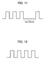
photosensitive members - However, there is generally a seam, or a gap, between the front and rear ends of the intermediate transfer belt. Upon encountering the gap, the sensor outputs detection pulses with a wider interval (see Fig. 11) than otherwise (see Fig. 12).
- Because of the wider pulses, a control system misjudges that the belt has slowed down, and erroneously performs feedback control to increase the belt speed.
- One approach is to control the belt speed by a dummy pulse stored in a RAM, etc., instead of using the pulse output by the sensor when the gap passes under the sensor.
- The average interval of the dummy pulses is the same as that of the pulses output by the sensor when reading the scale marks while the intermediate transfer belt is being driven at an ideal speed. Thus, by using this dummy pulse, the belt can be driven at an ideal speed even when the gap is encountering the sensor.
- When it is determined from the detection pulses that the gap is encountering the sensor, the control system controls the belt speed by using the dummy pulse. Thus, there is a need to quickly determine that the gap is encountering the sensor.
- If there is a delay in determining that the gap is encountering the sensor, the control system might continue using the detection pulse output from the sensor during the delay period and perform feedback control of the belt speed based on the detection pulses. In this case, the belt speed is erroneously increased before employing the dummy pulse. As a result, the belt speed cannot be accurately controlled.
- The sensor generally cannot immediately detect the gap when the front end of the scale reaches the sensor. The reason for this is because of the characteristic of an analog voltage output that is output by the sensor upon reading the scale marks of the scale. Fig. 13 depicts the characteristic of the analog voltage output that is output by the sensor upon reading the scale marks of the scale.
- An output voltage value α represents the output voltage value when the sensor is reading the scale marks. As the gap reaches the sensor, the voltage gradually drops. When the output voltage drops to a threshold β or less, the control system recognizes that the gap region has begun from this point on, and switches to controlling the belt speed based on the dummy pulses instead of the detection pulses.
- Accordingly, at the portion marked "x" in Fig. 13, the control system does not implement control using the dummy pulse even though the actual gap region has crossed the sensor. Consequently, the belt speed is controlled inaccurately, resulting in misaligned toner images and leading to degradation of color image.
- To solve this problem, a belt-speed control device having two sensors has been proposed. When a first sensor, provided upstream in the direction in which the belt is driven, detects the gap, a second sensor, provided downstream in the direction in which the belt is driven, controls the belt speed.
- However, the second sensor takes over the control only after the first sensor recognizes the gap, resulting in the delay as denoted by "x" in Fig. 13. Therefore, the problem remains unsolved.
- Japanese Patent Laid-Open Publication No. 2004-69933 discloses two examples of another belt-speed control device. In the first example, the surface of an endless belt is covered with a linear scale (scale seal) having a plurality of timing scale marks (pitches) along the circumferential direction. Three sensors with spaces therebetween in the circumferential direction are provided along the linear scale. Two of the sensors simultaneously read the linear scale and each sensor outputs a signal. A linear encoder receives the signals from both the sensors and synchronizes the pulse timings of the pulse signals of the two sensors. A controller controls the belt speed based on the signal output from the linear encoder.
- In a second example of this conventional belt speed detecting device, two linear scales forming two columns in the breadth direction of the endless belt are provided at shifted positions in the circumferential direction of the belt in such a manner that their edges overlap with each other. Two sensors are arranged so that each sensor reads one of the linear scales.
- However, in the first example, controlling the speed requires complex software to synchronize the timings of the pulse signals output by the two sensors.
- In the second example, the belt must be wide enough to accommodate two linear scales, which makes the scale of the device bigger. Further, arranging the two linear scales perfectly parallel to each other is a difficult task.
- It is an object of the present invention to at least solve the problems in the conventional technology.
- According to an aspect of the present invention, a device for controlling speed of a belt, wherein a scale including a plurality of equally spaced marks is attached to the belt in a direction of movement of the belt such that a gap is formed between a first end and a second end of the scale includes a first sensor configured to detect the marks on the scale and output a first signal upon detecting a mark among the marks, a second sensor configured to detect the marks on the scale and output a second signal upon detecting a mark among the marks, wherein the first sensor and the second sensor are located at different positions along the direction, and a controlling unit that controls the speed based on any one of the first signals and the second signals according to a position of the gap detected by the first sensor and the second sensor.
- According to another aspect of the present invention, a device for controlling speed of a belt, wherein a scale including a plurality of equally spaced marks is attached to the belt in a direction of movement of the belt such that a gap is formed between a first end and a second end of the scale includes a plurality of sensors configured to detect the marks on the scale and output signals upon detecting the marks, a first sensor among the plurality of sensors that outputs a first signal upon detecting a mark among the marks, a second sensor among the plurality of sensors that outputs a second signal upon detecting a mark among the marks, wherein the first sensor and the second sensor are located at different positions along the direction, and a controlling unit that controls the speed based on any one of the first signals and the second signals according to a position of the gap detected by the first sensor and the second sensor.
- According to still another aspect of the present invention, an image forming apparatus includes an image forming unit that forms images by movement of a belt, wherein a scale including a plurality of equally spaced marks is attached to the belt in a direction of movement of the belt such that a gap is formed between a first end and a second end of the scale, and a device that controls speed of the belt, including a first sensor configured to detect the marks on the scale and output a first signal upon detecting a mark among the marks, a second sensor configured to detect the marks on the scale and output a second signal upon detecting a mark among the marks, wherein the first sensor and the second sensor are located at different positions along the direction, and a controlling unit that controls the speed based on any one of the first signals and the second signals according to a position of the gap detected by the first sensor and the second sensor.
- According to still another aspect of the present invention, a method for controlling speed of a belt, wherein a scale including a plurality of equally spaced marks is attached to the belt in a direction of movement of the belt such that a gap is formed between a first end and a second end of the scale includes detecting the marks on the scale at a first position, detecting the marks on the scale at a second position, wherein the first position and the second position are located at different positions along the direction, and controlling the speed based on detection results at any one of the first position and the second position according to a position of the gap detected at any one of the first position and the second position.
- According to still another aspect of the present invention, a device for controlling speed of a belt, wherein a scale including a plurality of equally spaced marks is attached to the belt in a direction of movement of the belt such that a gap is formed between a first end and a second end of the scale includes first detecting means for detecting the marks on the scale and outputting a first signal upon detecting a mark among the marks, second detecting means for detecting the marks on the scale and outputting a second signal upon detecting a mark among the marks, wherein the first detecting means and the second detecting means are located at different positions along the direction, and controlling means for controlling the speed based on any one of the first signals and the second signals according to a position of the gap detected by the first detecting means and the second detecting means.
- The other objects, features, and advantages of the present invention are specifically set forth in or will become apparent from the following detailed description of the invention when read in conjunction with the accompanying drawings.
-
- Fig. 1 is a schematic of a belt-speed control device of an image forming apparatus according to an embodiment of the present invention;
- Fig. 2 depicts an overall configuration of the image forming apparatus according to the embodiment;
- Fig. 3 is a top view of the belt-speed control device shown in Fig. 1 including two sensors;
- Fig. 4 depicts two values output by the sensors shown in Fig. 3 upon reading scale marks of a scale;
- Fig. 5 is a block diagram of a controller of the image forming apparatus shown in Fig. 2;
- Fig. 6 is a flow chart of a belt speed feedback control routine performed by the controller shown in Fig. 5;
- Fig. 7 is a flow chart of the belt speed feedback control routine performed by switching between the two sensors shown in Fig. 3;
- Fig. 8 is a top view of the two sensors shown in Fig. 3 integrated into a single unit;
- Fig. 9 depicts an image forming unit of a conventional image forming apparatus employing a direct transfer method;
- Fig. 10 depicts an image forming unit of a conventional image forming apparatus employing an indirect transfer method;
- Fig. 11 depicts a detection pulse output by a sensor upon reading a scale seal with a gap;
- Fig. 12 depicts a detection pulse output by a sensor upon reading a scale seal without a gap; and
- Fig. 13 is a waveform diagram illustrating a change in voltage output by the sensor when the sensor encounters the gap of the scale seal as depicted with reference to Fig. 11.
- Exemplary embodiments of the present invention will be described below with reference to accompanying drawings. The present invention is not limited to these embodiments.
- Fig. 1 is a schematic diagram of a belt-speed control device of an image forming apparatus according to an embodiment of the present invention. Fig. 2 depicts an overall structure of the image forming apparatus according the embodiment. Fig. 3 is a top view of the belt-speed control device including two sensors that read scale marks provided on an intermediate transfer belt.
- In Fig. 2, a color copier is presented as an example of the image forming apparatus. The color copier is a tandem image forming apparatus and includes four drum-type photosensitive members (hereinafter, "photosensitive member 40" unless otherwise specified), 40Y, 40C, 40M, and 40K for the four colors yellow (Y), cyan (C), magenta (M), and black (K) and an
intermediate transfer belt 10 on which the image formed on each of the photosensitive members gets transferred at each first transfer position where a roller-typeprimary transfer device 62 is located. - The belt-speed control device of the image forming apparatus includes a scale 5 (only a portion of it is shown in Fig. 1) having a plurality of
scale marks 5a and aseam 11 in the circumferential direction. The scale is bonded to the entire surface of theintermediate transfer belt 10, as shown in Fig. 3. - A
sensor 6A and asensor 6B read the scale marks 5a of thescale 5 and each of thesensors controller 70 shown in Fig. 1 that functions as a control unit receives the output value and performs feedback control based on the output value to drive theintermediate transfer belt 10 at a uniform speed. - Feedback control involves detecting of the actual speed of the
intermediate transfer belt 10 by thesensor 6A and thesensor 6B by reading the scale marks 5a of thescale 5, and decreasing or increasing the actual speed of the intermediate transfer belt (hereinafter, "belt speed") to the target speed depending on the actual speed. - Out of the two
sensors sensor 6A is a primary sensor and thesensor 6B is a secondary sensor. Thesensor 6B is located upstream of thesensor 6A in the direction in which theintermediate transfer belt 10 is driven. - The belt-speed control device includes a sensor switching unit (provided in the
controller 70 in the embodiment). The sensor switching unit switches over feedback control from thesensor 6A to thesensor 6B in the period spanning from the moment arear end 11b of theseam 11 shown in Fig. 3 crosses the detection position of thesensor 6B (the secondary sensor) up until just before sensor A (the primary sensor) encounters theseam 11. - The color image forming apparatus shown in Fig. 2 has a copier
main unit 1 set on a paper feeding table 2. Ascanner 3 and an automatic document feeder (ADF) 4 are mounted on the copiermain unit 1. - The copier
main unit 1 includes atransfer device 20 in its mid portion. Thetransfer device 20 includes theintermediate transfer belt 10. Theintermediate transfer belt 10 is stretched over a drivingroller 9 and two drivenrollers belt cleaning device 17 located to the left of the drivenroller 15 removes a residual toner remaining after image transfer from the surface of theintermediate transfer belt 10. - The four photosensitive members 40 are located along the direction of movement of the
intermediate transfer belt 10 above the straight portion of theintermediate transfer belt 10 stretched between the drivingroller 9 and the drivenroller 15. Each of the photosensitive members 40 turns in a counter-clockwise direction. The image (toner image) formed on each of the photosensitive members 40 is superposed sequentially on theintermediate transfer belt 10. - Around each photosensitive member 40 are provided a
charging device 60, a developingdevice 61, theprimary transfer device 62, a photosensitivemember cleaning device 63, and aquenching device 64. An exposingdevice 21 is provided above the photosensitive member 40. - A
secondary transfer device 22 that transfers a sheet P, on which the image on theintermediate transfer belt 10 is recorded, is located below theintermediate transfer belt 10. Thesecondary transfer device 22 includes asecondary transfer belt 24, which is an endless belt, stretched across tworollers secondary transfer belt 24 presses against thesecondary roller 16 with theintermediate transfer belt 10 disposed between them. Thesecondary transfer device 22 transfers the toner images at once from theintermediate transfer belt 10 to the sheet P that is conveyed between thesecondary transfer belt 24 and theintermediate transfer belt 10. - A fixing
device 25 is located downstream of the sheet conveyance direction with respect to thesecondary transfer device 22. The fixingdevice 25 includes a fixingbelt 26, which is an endless belt, and apressure roller 27 pressed against the fixingbelt 26. - The
secondary transfer device 22 also performs the function of conveying the sheet P with the image formed thereon to the fixingdevice 25. A transfer roller or a non-contact charger can also be used as thesecondary transfer device 22. - A
sheet flipping device 28 that flips the sheet P when images are to be recorded on both sides of the sheet P is located below thesecondary transfer device 22. - When taking a color copy using the color copier, an original is normally placed on a
document dispenser 30 of theautomatic document feeder 4. However, the original can be placed manually after opening theautomatic document feeder 4 and placing the original on acontact glass 32 of thescanner 3 and pressing the original against thecontact glass 32 by closing theautomatic document feeder 4. - When a not shown switch is operated, the original placed on the
automatic document feeder 4 is automatically carried to thecontact glass 32. If the original is manually placed on thecontact glass 32, operating the switch starts afirst scanning member 33 and asecond scanning member 34 of thescanner 3. A beam from the light source of thefirst scanning member 33 exposes the original. The light reflected from the original is directed by a mirror of the first scanning member towards the second scanning member. This light hits a pair of mirrors of thesecond scanning member 34 and flips 180° upon hitting the mirrors. This reflected light then passes through animaging lens 35 and enters a readingsensor 36 that reads the content of the original. - When the start switch is operated, the
intermediate transfer belt 10 as well as thephotosensitive members photosensitive members intermediate transfer belt 10 that is driven clockwise in Fig. 2 and form a composite full color image. - Meanwhile, a feeding
roller 42 of the feeding rung selected from a paper feeding table 2 turns and the sheet P from a selected feedingcassette 44 in apaper bank 43 is rolled out and separated into single sheets by a separatingroller 45, and conveyed to a feedingchannel 48. - The sheet P comes in contact with a resist
roller 49 and comes to a stop for a while. - In the case of manual paper feeding, the sheets P placed in a
manual tray 51 are rolled out by a rollingfeeding roller 50, separated into single sheets by a separatingroller 52, and conveyed to amanual feeding channel 53. The sheet P then comes to a stop upon contact with the resistroller 49. - In either case, the resist
roller 49 starts turning synchronous with the color image on theintermediate transfer belt 10 and conveys the sheet P that has come to a halt between theintermediate transfer belt 10 and thesecondary transfer device 22 and causes the color image to be transferred to the sheet P by thesecondary transfer device 22. - The sheet P bearing the color image is conveyed by the
secondary transfer device 22 to the fixingdevice 25. The fixingdevice 25 fixes the color image by application of heat and pressure. The sheet P bearing a fixed color image is guided towards the exit by a switchingpawl 55 and is ejected by anejection roller 56 and is stacked on adischarge tray 57. - If "Both sides" mode is selected, the sheet P bearing the color image on one side is conveyed to the
sheet flipping device 28 by the switchingpawl 55. Thesheet flipping device 28 flips the sheet P and reintroduces the sheet P to the transfer position and allows the image to be formed on the reverse side. Once the image formation on the, reverse side is completed, the sheet P is ejected to thedischarge tray 57 by theejection roller 56. - As shown in Fig. 3, the
sensor 6A and thesensor 6B are set on the edge at a distance of Lp from each other, respectively in the direction of the belt movement, and read the scale 5 (also see Fig. 4) provided on the entire surface of the intermediate transfer belt 10 (thescale 5 can also be provided on the underside of the intermediate. transfer belt 10). The distance Lp is a mechanically set distance at the time of designing and corresponds to the distance from the edge of thesensor 6B where theintermediate transfer belt 10 enters and the edge of thesensor 6A where theintermediate transfer belt 10 emerges. As shown in Fig. 5, thecontroller 70 detects the actual speed of theintermediate transfer belt 10 from the data output by thesensor 6A and thesensor 6B upon reading of the scale marks 5a of thescale 5, and adjusts the actual speed of theintermediate transfer belt 10 to the target speed (standard speed) by controlling abelt driving motor 7. - The
controller 70 includes a micro-computer consisting of a central processing unit (CPU), a read-only memory (ROM), a random access memory (RAM), and an input/output (I/O) circuit. The CPU of the micro-computer performs functions related to determining processes and other processes. The ROM stores programs and data required for the various processes. The RAM is a data memory for storing process data. - The
controller 70 is connected to thesensor 6A and thesensor 6B as well as thebelt driving motor 7 so that it can perform feedback control of the belt speed. - The
controller 70 is also connected to the readingsensor 36, the exposingdevice 21 and animage forming unit 18 so that it can control the optical writing based on a detection result of the reading sensor and formation of the toner images in four colors by development, superposing and intermediate transfer. Apart from these, thecontroller 70 is connected to load-bearing members such as the driving system, etc. - The driving system of the
intermediate transfer belt 10 and the belt speed detecting system of theintermediate transfer belt 10 are explained next. - As shown in Fig. 1, the torque of the
belt driving motor 7 stretches and relays theintermediate transfer belt 10 to the drivingroller 9 so that theintermediate transfer belt 10 can be driven. Theintermediate transfer belt 10 is composed of fluoric resin, polycarbonate resin, polyimide resin, etc. All the layers or some of the layers of theintermediate transfer belt 10 can be made of an elastic material. - The
belt driving motor 7 drives theintermediate transfer belt 10 in the direction of the arrow C by turning the drivingroller 9. The torque can be relayed from thebelt driving motor 7 to the drivingroller 9 directly or via a gear system. - The
scale 5 is provided on the entire surface of the intermediate transfer belt 10 (in Fig. 3 only the vicinity of theseam 11 is shown). The position of thescale 5 in the width direction of theintermediate transfer belt 10 corresponds to the edge of the photosensitive member 40 and falls in the non-image forming area. - The
sensor 6A and thesensor 6B are identical. As shown in Fig. 4, both thesensor 6A and thesensor 6B are reflective optical sensors, each consisting of a pair ofphoto emitter 6a andphoto receiver 6b. Thephoto emitter 6a emits light towards thescale 5 and thephoto receiver 6b receives the light reflected from thescale 5. Thesensor 6A and thesensor 6B detect the difference in the amount of reflected light from the region of thescale 5 having thescale mark 5a and aregion 5b having no scale mark. - In other words, the
sensor 6A and thesensor 6B output signals having two values, namely High and Low, based on the difference in the reflection rate from the region of thescale 5 having thescale mark 5a and theregion 5b having no scale mark. - For example, if it is assumed that the
sensor 6A and thesensor 6B output High signal when the photo receiver receives light, and if the reflection rate from the region of thescale 5 having thescale mark 5a is higher than from theregion 5b having no scale mark, in the signal output by thesensor 6A or thesensor 6B, the range denoted by "t" in Fig. 4 denotes the output when thescale mark 5a has crossed thesensor 6A or thesensor 6B. Accordingly, as theintermediate transfer belt 10 is driven, thesensor 6A and thesensor 6B output either High or Low signal depending on whether a region having thescale mark 5a or theregion 5b with no scale mark has crossed thesensor 6A and thesensor 6B. - The speed of movement of the intermediate transfer belt 10 (belt speed) can be detected by determining a period T from the instant the signal turns from Low to High to the instant when the signal next turns Low or High.
- Any type of sensor or scale can be used as long as it is possible to detect the belt speed by reading the scale on the
intermediate transfer belt 10. - The
controller 70 shown in Fig. 5 performs the basic feedback control of the belt speed by implementing the routine shown in Fig. 6. That is, thecontroller 70 calculates a graduation detection pitch Pr based on an output voltage value output by thesensor 6A or thesensor 6B (step S601) (the selection of thesensor 6A or thesensor 6B is explained later). Thecontroller 70 performs the calculation by counting the difference between the rising portions of the High voltages (see Fig. 4) or the falling portions of the Low voltages. - The
controller 70 then determines whether the graduation detection pitch Pr obtained by calculation is equal to a basic pitch value Pb (T in Fig. 4 in this example) (step S602). If Pr is found to be equal to Pb ("Yes" at step S602), thecontroller 70 determines that no change has occurred in the belt speed and returns to the main routine. If Pr is found to be not equal to Pb ("No" at step S602), thecontroller 70 determines that a change has occurred in the belt speed and increases or decreases the rotation speed of thebelt driving motor 7 by the ratio corresponding to the value "Pr-Pb" (step S603). - Thus, the color image forming apparatus prevents any variation in the belt speed by performing feedback control of the
belt driving motor 7 based on the result obtained by comparing the graduation detection pitch Pr and the basic pitch value Pb. - If the value of "Pr-Pb" is positive, the
controller 70 speeds up thebelt driving motor 7 by the ratio corresponding to the obtained value. Conversely, if the value of "Pr-Pb is negative, thecontroller 70 slows down thebelt driving motor 7 by the ratio corresponding to the obtained value. - The
controller 70 entirely performs feedback control of theintermediate transfer belt 10, thus preventing variation in the belt speed and the resulting image degradation due to shifted superposition of the toner images. - When the belt-shaped
long scale 5 is bonded to the surface of theintermediate transfer belt 10, even if thescale 5 itself is of accurate length, due to variation in the perimeter of theintermediate transfer belt 10, a gap S shown in Fig. 3 can be formed at theseam 11 between one end (front end 11a) of theseam 11 and the other end (rear end 11b) of theseam 11. - If such a gap is formed at the
seam 11 of thescale 5, the interval between ascale mark 5a', which is a high reflectance region closest to theseam 11 at thefront end 11a side, and ascale mark 5a", which is a high reflectance region closest to theseam 11 at therear end 11b side, becomes larger than the intervals betweenscale marks 5a in regions other than at theseam 11. - Therefore, at the
seam 11, the occurrence time of the rising portion of the High voltage and the falling portion of the Low voltage, explained with reference to Fig. 4, gets delayed to the extent of the gap S at theseam 11. - As a result, the graduation detection pitch Pr, which corresponds to a length L3 obtained by adding a length L1 of the
scale mark 5a and a length L2 of theregion 5b having no scale mark, becomes Pr' at theseam 11, which is obtained by adding the length of the gap S to the graduation detection pitch Pr. - Thus, the pitch between the
scale mark 5a' and thescale mark 5a" changes from the normal graduation detection pitch Pr to Pr', forming an abnormal pitch region, even if the belt speed has not changed. - When encountering the abnormal pitch region at the
seam 11, thecontroller 70 mistakenly determines that the belt speed has fallen and performs feedback control, speeding up the belt. Consequently, the superposition of the toner images transferred to theintermediate transfer belt 10 is shifted leading to color inconsistency in the image. - Therefore, in the color image forming apparatus according to the embodiment, by providing two sensors, the
sensor 6A and thesensor 6B, and switching over the control of belt speed from thesensor 6A to thesensor 6B in the period spanning from the moment the rear end of theseam 11 crosses the detection position of thesensor 6B up until just before thesensor 6A encounters theseam 11, uniform belt speed is maintained even when theseam 11 is encountered. Consequently, shift in the superposition of the toner images and the resulting image degradation due to color inconsistency can be prevented. - The distance Lp between the
sensor 6A and thesensor 6B is a mechanically set distance at the time of designing. Thesensor 6A and thesensor 6B need not be two separate entities, as shown in Fig. 3, but can be integrated into a single unit. Fig. 8 is a top view of two sensors integrated into a single unit. Integrating two sensors into a single unit as shown in Fig. 8 helps avoid shifting of the sensors over long periods of use and maintain a constant distance Lp between the sensors. As a result, the control is switched between the sensors without delay and a uniform speed of theintermediate transfer belt 10 can be maintained. - Fig. 7 is a flow chart of the belt speed feedback control routine performed by implementing the belt speed control method involving switching the control of the speed belt between the two sensors.
- When a program related to the feedback control process of the belt speed is initiated, the
controller 70 assigns control of belt speed to thesensor 6A and uses the output value of thesensor 6A to perform feedback control (step S701). Thecontroller 70 performs the belt speed control (the basic feedback control of belt speed) explained with reference to Fig. 6 based on the output value of thesensor 6A (step S702). - Next, the
controller 70 determines whether thesensor 6B has encountered theseam 11, that is, whether therear end 11b of theseam 11 has crossed the detection position of thesensor 6B (step S703). If it is determined that therear end 11b has not crossed thesensor 6B ("No" at step S703), the process returns to step S701. - If it is determined that the
rear end 11b has crossed the detection position of thesensor 6B ("Yes" at step S703), thecontroller 70 determines whether it is time to switch over the control of the belt speed to thesensor 6B (step S704). - The switching time spans from the instant the
rear end 11b of theseam 11 crosses the detection position of thesensor 6B up until just before thesensor 6A encounters theseam 11. More specifically, the switching time corresponds to a period spanning from the time the length of theintermediate transfer belt 10 corresponding to the gap S of theseam 11 crosses thesensor 6B after thesensor 6B encounters thefront end 11a of theseam 11 on theintermediate transfer belt 10 up until just before the length of theintermediate transfer belt 10 corresponding to the gap S of theseam 11 traverses the distance Lp (more accurately, the distance obtained after deducting the width of thesensor 6A from the distance Lp) between thesensor 6B and thesensor 6A after thesensor 6B encounters thefront end 11a of theseam 11 on theintermediate transfer belt 10. - For example, assuming that the time taken by the
intermediate transfer belt 10 to traverse the distance Lp is 70 ms, and that there are tenscale marks 5a in the distance Lp, it can be surmised that it takes 7 ms for theintermediate transfer belt 10 to traverse the distance corresponding to onescale mark 5a. When theintermediate transfer belt 10 traverses the distance up to the9th scale mark controller 70 switches over the control from thesensor 6A to thesensor 6B after 60 ms have elapsed, that is, 3 ms before theintermediate transfer belt 10 traverses the distance corresponding to ninescale marks 5a. - When the
seam 11 crosses thesensor 6B, thecontroller 70 determines the time required for theseam 11 to traverse the pre-stored distance Lp between thesensor 6B and thesensor 6A and sets, as the switching time, the time immediately before theseam 11 reaches thesensor 6A. - If it is determined that it is not yet time for switching over the control of the belt speed to sensor B ("No" at step S704), the
controller 70 repeats the process until it is time to switch over the control. If it is determined that it is time to switch over the control to thesensor 6B ("Yes" at step S704), thecontroller 70 assigns control of the speed belt to thesensor 6B and uses the output value of thesensor 6B for performing feedback control of the belt speed (step S705). Thecontroller 70 performs the belt speed control (the basic feedback control of belt speed) explained with reference to Fig. 6 based on the output value of thesensor 6B (step S706). - Next, the
controller 70 determines whether theseam 11 has completely crossed the detection position of thesensor 6A (step S707). Theseam 11 completely crossing the detection position of thesensor 6A indicates that theintermediate transfer belt 10 has traversed a distance which is greater than the distance obtained by adding the gap S at theseam 11 to the distance Lp, which is the distance between thesensor 6A and thesensor 6B, after the sensor B detects thefront end 11a of theseam 11 on theintermediate transfer belt 10. - If it is determined that the
seam 11 has not completely crossed the detection position of thesensor 6A ("No" at step S707), the process returns to step S705. If it is determined that theseam 11 has completely crossed thesensor 6A ("Yes" at step S707), thecontroller 70 determines whether a stop belt signal has been input (step S708). The stop belt signal is a signal that stops theintermediate transfer belt 10. If it is determined that no stop belt signal has been input ("No" at step S708), the process returns to step S701 as the image forming operation continues uninterrupted, where thecontroller 70 reassigns control of the belt speed to thesensor 6A, and performs feedback control of the belt speed based on the output value of thesensor 6A. The subsequent steps are repeated. - If it is determined that the stop belt signal has been input ("Yes" at step S708), the process is ended.
- Thus, in the embodiment, when the
sensor 6B encounters theseam 11, feedback control of the belt speed is performed based on the output value of thesensor 6A. When theseam 11 reaches thesensor 6A, the output value of thesensor 6A, which would be inaccurate due to the abnormal pitch region at theseam 11 being read by thesensor 6A, is not used, and instead the output value of thesensor 6B, which would be accurate, is used for performing feedback control of the belt speed. Consequently, by switching over the control of the belt speed to the sensor that is not affected by theseam 11, uniform belt speed is maintained even if theseam 11 is detected thefront end 11a of theseam 11 has crossed the sensor. As a result, degradation of image quality due to shifted toner images can be prevented. - Furthermore, the belt speed can be controlled accurately with a software that helps maintain a uniform belt speed based on the signal from the sensors. Thus, the need for a complex software is obviated.
- Apart from the aforementioned switching time determination method, the control of belt speed can also be switched over from the
sensor 6B back to thesensor 6A when thesensor 6A detects input of a normal detection signal (a signal from the region having the equidistant scale marks 5a) . - The control of the belt speed can be switched from the
sensor 6B to thesensor 6A at any timing as long as theseam 11 has completely crossed thesensor 6A, and therefore, there is no need to provide a counter for counting time for this switching. However, the control of the belt speed should be switched back to the sensor A until theseam 11 is detected by the sensor B in the next lap. - It is preferable to time the switching of the control from the
sensor 6B to thesensor 6A when image formation is not taking place after theseam 11 has crossed thesensor 6A rather than when image formation is taking place, as the control of belt speed is not affected, so that the final image is not adversely affected. - In the embodiment, the time just before the
seam 11 reaches the sensor A after traversing the pre-stored distance Lp between thesensor 6B and thesensor 6A is set as the time for switching the control of the belt speed from one sensor to the other. When the belt speed varies, such as when thebelt driving motor 7 is started up, the time when theseam 11 is about to cross thesensor 6A or cross past thesensor 6A does not remain constant, thus leading to improper control of belt speed. - Therefore, when the belt driving motor (driving source that drives the belt) 7 is just started up and its speed tends to vary, it is preferable to halt the
intermediate transfer belt 10 in such a way that theseam 11 does not lie between thesensor 6A and thesensor 6B or very close to either thesensor 6A or thesensor 6B. This control is also performed by thecontroller 70. - An image forming program executed by the image forming apparatus according to the embodiment can be made readily available on a read-only memory (ROM).
- The image forming program executed by the image forming apparatus according to the embodiment can be recorded in an installable format on a computer-readable recording medium such as a compact disk-read-only memory (CD-ROM), flexible disk (FD), compact disk - recordable (CD-R), digital versatile disk (DVD), etc.
- The image forming program executed by the image forming device according to the embodiment can be stored on a computer connected to a network, such as the Internet, and can be downloaded via the network. The image forming program can be provided or distributed via the network.
- The image forming program executed by the image forming apparatus according to the embodiment can be in the form of a module that includes the
controller 70. The CPU (processor) reads the image forming program from the ROM and loads thecontroller 70 to a primary storage device to generate thecontroller 70 on the primary storage device. - The present invention has wide application as an image forming apparatus having a belt-speed control device, a program for belt speed control, and a belt speed control method.
- According to an aspect of the present invention, a belt speed can be accurately controlled without requiring complex software, so that misalignment of toner images can be reliably prevented.
- Although the invention has been described with respect to a specific embodiment for a complete and clear disclosure, the appended claims are not to be thus limited but are to be construed as embodying all modifications and alternative constructions that may occur to one skilled in the art which fairly fall within the basic teaching herein set forth.
Claims (19)
- A device for controlling speed of a belt (10), wherein a scale (5) including a plurality of equally spaced marks (5a) is attached to the belt (10) in a direction of movement of the belt (10) such that a gap (11) is formed between a first end (11a) and a second end (11b) of the scale (5), the device comprising:a first sensor (6A) configured to detect the marks (5a) on the scale (5) and output a first signal upon detecting a mark among the marks (5a);a second sensor (6B) configured to detect the marks (5a) on the scale (5) and output a second signal upon detecting a mark among the marks (5a), wherein the first sensor (6A) and the second sensor (6B) are located at different positions along the direction; anda controlling unit (70) that controls the speed based on any one of the first signals and the second signals according to a position of the gap (11) detected by the first sensor (6A) and the second sensor (6B).
- The device according to claim 1, wherein
the second end (11b) is positioned upstream than the first end (11a) in the direction,
the second sensor (6B) is positioned upstream than the first sensor (6A) in the direction, and
the controlling unit (70) switches from controlling the speed based on the first signals to controlling the speed based on the second signals after the second sensor (6B) detects the second end (11b) and before the first sensor (6A) detects the first end (11a) . - The device according to claim 2, wherein
the controlling unit (70) switches from controlling the speed based on the first signals to controlling the speed based on the second signals after the first end (11a) moves a distance corresponding to the gap (11) from when the second sensor (6B) detects the first end (11a) and before the first end (11a) moves a distance corresponding to a space between the first sensor (6A) and the second sensor (6B) from the when the second sensor (6B) detects the first end (11a). - The device according to claim 3, wherein
the controlling unit (70) switches from controlling the speed based on the first signals to controlling the speed based on the second signals at a timing immediately before the first end (11a) reaches the first sensor (6A), wherein the timing is calculated when the second sensor (6B) detects the first end (11a) based on the distance corresponding to the space between the first sensor (6A) and the second sensor (6B). - The device according to claim 1, wherein
the second end (11b) is positioned upstream than the first end (11a) in the direction,
the second sensor (6B) is positioned upstream than the first sensor (6A) in the direction, and
the controlling unit (70) switches from controlling the speed based on the second signals to controlling the speed based on the first signals after the first end (11a) moves a distance corresponding a space between the first sensor (6A) and the second sensor (6B) in addition to a distance corresponding to the gap (11) from when the second sensor detects (6B) the first end (11a). - The device according to claim 1, wherein
the controlling unit (70) controls the belt (10) such that the gap (11) is not positioned between the first sensor (6A) and the second sensor (6B) while a driving source (7) that drives the belt (10) is starting up. - An image forming apparatus comprising:an image forming unit (18) that forms images by movement of a belt (10), wherein a scale (5) including a plurality of equally spaced marks (5a) is attached to the belt (10) in a direction of movement of the belt (10) such that a gap (11) is formed between a first end (11a) and a second end (11b) of the scale (5); anda device that controls speed of the belt (10), including
a first sensor (6A) configured to detect the marks (5a) on the scale (5) and output a first signal upon detecting a mark among the marks (5a);
a second sensor (6B) configured to detect the marks (5a) on the scale (5) and output a second signal upon detecting a mark among the marks (5a), wherein the first sensor (6A) and the second sensor (6B) are located at different positions along the direction; and
a controlling unit (70) that controls the speed based on any one of the first signals and the second signals according to a position of the gap (11) detected by the first sensor (6A) and the second sensor (6B). - The image forming apparatus according to claim 7, wherein
the second end (11b) is positioned upstream than the first end (11a) in the direction,
the second sensor (6B) is positioned upstream than the first sensor (6A) in the direction, and
the controlling unit (70) switches from controlling the speed based on the first signals to controlling the speed based on the second signals after the second sensor (6B) detects the second end (11b) and before the first sensor (6A) detects the first end (11a). - The image forming apparatus according to claim 8, wherein
the controlling unit (70) switches from controlling the speed based on the first signals to controlling the speed based on the second signals after the first end (11a) moves a distance corresponding to the gap (11) from when the second sensor (6B) detects the first end (11a) and before the first end (11a) moves a distance corresponding to a space between the first sensor (6A) and the second sensor (6B) from the when the second sensor (6B) detects the first end (11a). - The image forming apparatus according to claim 9, wherein
the controlling unit (70) switches from controlling the speed based on the first signals to controlling the speed based on the second signals at a timing immediately before the first end (11a) reaches the first sensor (6A), wherein the timing is calculated when the second sensor (6B) detects the first end (11a) based on the distance corresponding to the space between the first sensor (6A) and the second sensor (6B). - The image forming apparatus according to claim 7, wherein
the second end (11b) is positioned upstream than the first end (11a) in the direction,
the second sensor (6B) is positioned upstream than the first sensor (6A) in the direction, and
the controlling unit (70) switches from controlling the speed based on the second signals to controlling the speed based on the first signals after the first end (11a) moves a distance corresponding a space between the first sensor (6A) and the second sensor (6B) in addition to a distance corresponding to the gap (11) from when the second sensor (6B) detects the first end (11a). - The image forming apparatus according to claim 7, wherein
the controlling unit (70) controls the belt (10) such that the gap (11) is not positioned between the first sensor (6A) and the second sensor (6B) while a driving source (7) that drives the belt (10) is starting up. - A method for controlling speed of a belt, wherein a scale including a plurality of equally spaced marks is attached to the belt in a direction of movement of the belt such that a gap is formed between a first end and a second end of the scale, the method comprising:detecting the marks on the scale at a first position;detecting the marks on the scale at a second position, wherein the first position and the second position are located at different positions along the direction; andcontrolling the speed based on detection results at any one of the first position and the second position according to a position of the gap detected at any one of the first position and the second position.
- A device for controlling speed of a belt (10), wherein a scale (5) including a plurality of equally spaced marks (5a) is attached to the belt (10) in a direction of movement of the belt (10) such that a gap (11) is formed between a first end (11a) and a second end (11b) of the scale(5), the device comprising:first detecting means (6A) for detecting the marks (5a) on the scale (5) and outputting a first signal upon detecting a mark among the marks (5a);second detecting means (6B) for detecting the marks (5a) on the scale (5) and outputting a second signal upon detecting a mark among the marks (5a), wherein the first detecting means (6A) and the second detecting means (6B) are located at different positions along the direction; andcontrolling means (70) for controlling the speed based on any one of the first signals and the second signals according to a position of the gap (11) detected by the first detecting means (6A) and the second detecting means (6B) .
- The device according to claim 14, wherein
the second end (11b) is positioned upstream than the first end (11a) in the direction,
the second detecting means (6B) is positioned upstream than the first detecting means (6A) in the direction, and
the controlling means (70) switches from controlling the speed based on the first signals to controlling the speed based on the second signals after the second detecting means (6B) detects the second end (11b) and before the first detecting means (6A) detects the first end (11a). - The device according to claim 15, wherein
the controlling means (70) switches from controlling the speed based on the first signals to controlling the speed based on the second signals after the first end (11a) moves a distance corresponding to the gap (11) from when the second detecting means (6B) detects the first end (11a) and before the first end (11a) moves a distance corresponding to a space between the first detecting means (6A) and the second detecting means (6B) from the when the second detecting means (6B) detects the first end (11a). - The device according to claim 16, wherein
the controlling means (70) switches from controlling the speed based on the first signals to controlling the speed based on the second signals at a timing immediately before the first end (11a) reaches the first detecting means (6A), wherein the timing is calculated when the second detecting means (6B) detects the first end (11a) based on the distance corresponding to the space between the first detecting means (6A) and the second detecting means (6B). - The device according to claim 14, wherein
the second end (11b) is positioned upstream than the first end (11a) in the direction,
the second detecting means (6B) is positioned upstream than the first detecting means (6A) in the direction, and
the controlling means (70) switches from controlling the speed based on the second signals to controlling the speed based on the first signals after the first end (11a) moves a distance corresponding a space between the first detecting means (6A) and the second detecting means (6B) in addition to a distance corresponding to the gap (11) from when the second detecting means (6B) detects the first end (11a) . - The device according to claim 14, wherein
the controlling means (70) controls the belt such that the gap (11) is not positioned between the first detecting means (6A) and the second detecting means (6B) while a driving source (7) that drives the belt (10) is starting up.
Applications Claiming Priority (1)
| Application Number | Priority Date | Filing Date | Title |
|---|---|---|---|
| JP2004343314A JP4576215B2 (en) | 2004-11-29 | 2004-11-29 | Belt speed control device, program, image forming apparatus, and belt speed control method |
Publications (2)
| Publication Number | Publication Date |
|---|---|
| EP1662330A1 true EP1662330A1 (en) | 2006-05-31 |
| EP1662330B1 EP1662330B1 (en) | 2007-03-21 |
Family
ID=35789129
Family Applications (1)
| Application Number | Title | Priority Date | Filing Date |
|---|---|---|---|
| EP05025495A Ceased EP1662330B1 (en) | 2004-11-29 | 2005-11-23 | Device and method for belt speed control, and image forming apparatus |
Country Status (4)
| Country | Link |
|---|---|
| US (1) | US7424255B2 (en) |
| EP (1) | EP1662330B1 (en) |
| JP (1) | JP4576215B2 (en) |
| DE (1) | DE602005000746T2 (en) |
Families Citing this family (14)
| Publication number | Priority date | Publication date | Assignee | Title |
|---|---|---|---|---|
| JP2006178374A (en) * | 2004-12-24 | 2006-07-06 | Brother Ind Ltd | Image forming apparatus |
| JP4584864B2 (en) * | 2005-05-27 | 2010-11-24 | 株式会社リコー | Belt drive device, image forming apparatus, belt drive method, and program |
| JP5294617B2 (en) * | 2007-12-05 | 2013-09-18 | キヤノン株式会社 | Image forming apparatus |
| JP5107011B2 (en) * | 2007-12-12 | 2012-12-26 | 株式会社リコー | Drive control apparatus and image forming apparatus having the same |
| JP2009244743A (en) * | 2008-03-31 | 2009-10-22 | Fuji Xerox Co Ltd | Image forming apparatus belt, belt stretching device, and image forming apparatus |
| JP5257169B2 (en) * | 2009-03-13 | 2013-08-07 | 株式会社リコー | Image forming apparatus |
| JP5288190B2 (en) * | 2009-03-16 | 2013-09-11 | 株式会社リコー | Endless moving member drive control device, image forming apparatus, endless moving member drive control method, program, and recording medium |
| US8180266B2 (en) * | 2009-06-03 | 2012-05-15 | Xerox Corporation | Method, apparatus and systems for registering the transfer of an image associated with a printing device |
| JP5402288B2 (en) * | 2009-06-18 | 2014-01-29 | 株式会社リコー | Image forming apparatus, image forming method, and program |
| JP5596946B2 (en) * | 2009-08-05 | 2014-09-24 | キヤノン株式会社 | Image reading apparatus and method for controlling image reading apparatus |
| JP5907619B2 (en) * | 2011-04-20 | 2016-04-26 | キヤノン株式会社 | Image forming apparatus |
| JP2013171175A (en) * | 2012-02-21 | 2013-09-02 | Canon Inc | Rotary drive device, rotary drive control method, and image formation apparatus |
| JP2014106281A (en) * | 2012-11-26 | 2014-06-09 | Canon Inc | Speed detection device, and driving mechanism control device |
| JP6891696B2 (en) * | 2017-07-24 | 2021-06-18 | 株式会社リコー | Image forming device |
Citations (3)
| Publication number | Priority date | Publication date | Assignee | Title |
|---|---|---|---|---|
| US5383014A (en) * | 1993-05-20 | 1995-01-17 | Xerox Corporation | Photoreceptor belt motion sensor using linear position sensors |
| JP2001034025A (en) * | 1999-07-16 | 2001-02-09 | Canon Inc | Image forming device |
| US20040022557A1 (en) * | 2002-03-22 | 2004-02-05 | Koichi Kudo | Drive control device and image forming apparatus including the same |
Family Cites Families (23)
| Publication number | Priority date | Publication date | Assignee | Title |
|---|---|---|---|---|
| JPH01157668A (en) | 1987-12-15 | 1989-06-20 | Matsushita Electric Ind Co Ltd | Original reading device |
| JP2946520B2 (en) | 1989-03-02 | 1999-09-06 | ミノルタ株式会社 | Image reading device |
| JPH06113089A (en) | 1992-09-30 | 1994-04-22 | Toshiba Corp | Information reader |
| US5272492A (en) * | 1992-12-01 | 1993-12-21 | Xerox Corporation | Compensation of magnification mismatch in single pass color printers |
| JPH07245682A (en) | 1994-03-02 | 1995-09-19 | Minolta Co Ltd | Image reader and copying machine incorporating it |
| JPH0927909A (en) | 1995-07-13 | 1997-01-28 | Ricoh Co Ltd | Image reading device |
| JPH09172525A (en) | 1995-12-19 | 1997-06-30 | Canon Inc | Image reading device |
| JP3344614B2 (en) * | 1995-12-27 | 2002-11-11 | 富士ゼロックス株式会社 | Belt transport device |
| JPH09200449A (en) | 1996-01-18 | 1997-07-31 | Canon Inc | Image processing apparatus and method |
| JPH09298628A (en) | 1996-05-02 | 1997-11-18 | Ricoh Co Ltd | Image reading device |
| JP3625962B2 (en) | 1996-09-25 | 2005-03-02 | 株式会社リコー | Image reading device |
| JPH10232566A (en) * | 1997-02-19 | 1998-09-02 | Canon Inc | Image forming device |
| JP3640287B2 (en) | 1998-07-01 | 2005-04-20 | 株式会社リコー | Scanner control device and image forming apparatus |
| JP3995845B2 (en) | 1999-09-14 | 2007-10-24 | 株式会社リコー | Image reading apparatus, copying machine, and facsimile machine |
| US6336019B2 (en) * | 1999-11-29 | 2002-01-01 | Xerox Corporation | Surface position and velocity measurement for photoreceptor belt |
| JP4294254B2 (en) * | 2002-03-22 | 2009-07-08 | 株式会社リコー | Drive control apparatus and image forming apparatus |
| JP3893300B2 (en) * | 2002-03-22 | 2007-03-14 | 株式会社リコー | Drive control device and image forming apparatus |
| JP2004069933A (en) | 2002-08-05 | 2004-03-04 | Hitachi Ltd | Speed detector and image forming apparatus |
| JP2004170929A (en) * | 2002-11-06 | 2004-06-17 | Ricoh Co Ltd | Belt device, image forming apparatus, and belt member drive control method |
| JP2004191845A (en) * | 2002-12-13 | 2004-07-08 | Ricoh Co Ltd | Transfer device |
| JP4755400B2 (en) * | 2003-08-29 | 2011-08-24 | 株式会社リコー | Endless moving member driving device, image forming apparatus, photoreceptor driving device, and endless moving member deterioration warning method |
| US7576509B2 (en) * | 2003-09-10 | 2009-08-18 | Ricoh Company, Limited | Drive control method, drive control device, belt apparatus, image forming apparatus, image reading apparatus, computer product |
| JP4584864B2 (en) * | 2005-05-27 | 2010-11-24 | 株式会社リコー | Belt drive device, image forming apparatus, belt drive method, and program |
-
2004
- 2004-11-29 JP JP2004343314A patent/JP4576215B2/en not_active Expired - Fee Related
-
2005
- 2005-11-21 US US11/282,868 patent/US7424255B2/en not_active Expired - Fee Related
- 2005-11-23 DE DE602005000746T patent/DE602005000746T2/en not_active Expired - Lifetime
- 2005-11-23 EP EP05025495A patent/EP1662330B1/en not_active Ceased
Patent Citations (3)
| Publication number | Priority date | Publication date | Assignee | Title |
|---|---|---|---|---|
| US5383014A (en) * | 1993-05-20 | 1995-01-17 | Xerox Corporation | Photoreceptor belt motion sensor using linear position sensors |
| JP2001034025A (en) * | 1999-07-16 | 2001-02-09 | Canon Inc | Image forming device |
| US20040022557A1 (en) * | 2002-03-22 | 2004-02-05 | Koichi Kudo | Drive control device and image forming apparatus including the same |
Non-Patent Citations (1)
| Title |
|---|
| PATENT ABSTRACTS OF JAPAN vol. 2000, no. 19 5 June 2001 (2001-06-05) * |
Also Published As
| Publication number | Publication date |
|---|---|
| EP1662330B1 (en) | 2007-03-21 |
| DE602005000746D1 (en) | 2007-05-03 |
| JP4576215B2 (en) | 2010-11-04 |
| US20060133861A1 (en) | 2006-06-22 |
| US7424255B2 (en) | 2008-09-09 |
| JP2006154162A (en) | 2006-06-15 |
| DE602005000746T2 (en) | 2007-12-06 |
Similar Documents
| Publication | Publication Date | Title |
|---|---|---|
| EP1662330B1 (en) | Device and method for belt speed control, and image forming apparatus | |
| US6356735B1 (en) | Sheet transport device and an image-forming apparatus employing the sheet transport device | |
| JP3970826B2 (en) | Image forming apparatus | |
| EP1517192B1 (en) | Color image forming apparatus | |
| JP2006171352A (en) | Color image forming apparatus | |
| US20040156654A1 (en) | Belt driver, image forming apparatus, and method that can reduce the time until speed control of a blet is performed | |
| JP4584864B2 (en) | Belt drive device, image forming apparatus, belt drive method, and program | |
| JP4477412B2 (en) | Belt device, image forming apparatus including the belt device, and belt speed control method | |
| JP4298157B2 (en) | Image forming apparatus | |
| US5279453A (en) | Automatic document feeder capable of feeding a document in the form of a computer form | |
| US5259544A (en) | Automatic document feeder capable of feeding a document in the form of computer form paper | |
| JP4613647B2 (en) | Image forming apparatus and image output apparatus | |
| JP4560389B2 (en) | Image forming apparatus | |
| CN108732883B (en) | Image forming apparatus with a toner supply device | |
| JPH0962047A (en) | Color image forming device | |
| JP4770624B2 (en) | Color image forming apparatus | |
| JP2008129518A (en) | Belt moving device and image forming apparatus | |
| JP5288190B2 (en) | Endless moving member drive control device, image forming apparatus, endless moving member drive control method, program, and recording medium | |
| JP2020148837A (en) | Media detection device and image forming device | |
| EP1594016B1 (en) | Belt device, image forming apparatus, and method to control belt speed | |
| JP2006021904A (en) | Image forming device | |
| JP2005043439A (en) | Image forming apparatus | |
| JP5018636B2 (en) | Image forming apparatus | |
| JP2003156905A (en) | Color image forming equipment | |
| JP2004341413A (en) | Image forming device |
Legal Events
| Date | Code | Title | Description |
|---|---|---|---|
| PUAI | Public reference made under article 153(3) epc to a published international application that has entered the european phase |
Free format text: ORIGINAL CODE: 0009012 |
|
| AK | Designated contracting states |
Kind code of ref document: A1 Designated state(s): AT BE BG CH CY CZ DE DK EE ES FI FR GB GR HU IE IS IT LI LT LU LV MC NL PL PT RO SE SI SK TR |
|
| AX | Request for extension of the european patent |
Extension state: AL BA HR MK YU |
|
| 17P | Request for examination filed |
Effective date: 20060627 |
|
| 17Q | First examination report despatched |
Effective date: 20060728 |
|
| GRAP | Despatch of communication of intention to grant a patent |
Free format text: ORIGINAL CODE: EPIDOSNIGR1 |
|
| AKX | Designation fees paid |
Designated state(s): DE FR GB |
|
| GRAS | Grant fee paid |
Free format text: ORIGINAL CODE: EPIDOSNIGR3 |
|
| GRAA | (expected) grant |
Free format text: ORIGINAL CODE: 0009210 |
|
| AK | Designated contracting states |
Kind code of ref document: B1 Designated state(s): DE FR GB |
|
| REG | Reference to a national code |
Ref country code: GB Ref legal event code: FG4D |
|
| REF | Corresponds to: |
Ref document number: 602005000746 Country of ref document: DE Date of ref document: 20070503 Kind code of ref document: P |
|
| PLBE | No opposition filed within time limit |
Free format text: ORIGINAL CODE: 0009261 |
|
| STAA | Information on the status of an ep patent application or granted ep patent |
Free format text: STATUS: NO OPPOSITION FILED WITHIN TIME LIMIT |
|
| 26N | No opposition filed |
Effective date: 20071227 |
|
| REG | Reference to a national code |
Ref country code: FR Ref legal event code: PLFP Year of fee payment: 11 |
|
| REG | Reference to a national code |
Ref country code: FR Ref legal event code: PLFP Year of fee payment: 12 |
|
| REG | Reference to a national code |
Ref country code: FR Ref legal event code: PLFP Year of fee payment: 13 |
|
| PGFP | Annual fee paid to national office [announced via postgrant information from national office to epo] |
Ref country code: DE Payment date: 20181120 Year of fee payment: 14 |
|
| PGFP | Annual fee paid to national office [announced via postgrant information from national office to epo] |
Ref country code: FR Payment date: 20181123 Year of fee payment: 14 Ref country code: GB Payment date: 20181120 Year of fee payment: 14 |
|
| REG | Reference to a national code |
Ref country code: DE Ref legal event code: R119 Ref document number: 602005000746 Country of ref document: DE |
|
| GBPC | Gb: european patent ceased through non-payment of renewal fee |
Effective date: 20191123 |
|
| PG25 | Lapsed in a contracting state [announced via postgrant information from national office to epo] |
Ref country code: DE Free format text: LAPSE BECAUSE OF NON-PAYMENT OF DUE FEES Effective date: 20200603 Ref country code: GB Free format text: LAPSE BECAUSE OF NON-PAYMENT OF DUE FEES Effective date: 20191123 Ref country code: FR Free format text: LAPSE BECAUSE OF NON-PAYMENT OF DUE FEES Effective date: 20191130 |