EP1662291A1 - An optical scanner - Google Patents
An optical scanner Download PDFInfo
- Publication number
- EP1662291A1 EP1662291A1 EP05253385A EP05253385A EP1662291A1 EP 1662291 A1 EP1662291 A1 EP 1662291A1 EP 05253385 A EP05253385 A EP 05253385A EP 05253385 A EP05253385 A EP 05253385A EP 1662291 A1 EP1662291 A1 EP 1662291A1
- Authority
- EP
- European Patent Office
- Prior art keywords
- spinner
- axis
- optical scanner
- scan
- scanner
- Prior art date
- Legal status (The legal status is an assumption and is not a legal conclusion. Google has not performed a legal analysis and makes no representation as to the accuracy of the status listed.)
- Granted
Links
Images




Classifications
-
- G—PHYSICS
- G06—COMPUTING OR CALCULATING; COUNTING
- G06K—GRAPHICAL DATA READING; PRESENTATION OF DATA; RECORD CARRIERS; HANDLING RECORD CARRIERS
- G06K7/00—Methods or arrangements for sensing record carriers, e.g. for reading patterns
- G06K7/10—Methods or arrangements for sensing record carriers, e.g. for reading patterns by electromagnetic radiation, e.g. optical sensing; by corpuscular radiation
- G06K7/10544—Methods or arrangements for sensing record carriers, e.g. for reading patterns by electromagnetic radiation, e.g. optical sensing; by corpuscular radiation by scanning of the records by radiation in the optical part of the electromagnetic spectrum
- G06K7/10821—Methods or arrangements for sensing record carriers, e.g. for reading patterns by electromagnetic radiation, e.g. optical sensing; by corpuscular radiation by scanning of the records by radiation in the optical part of the electromagnetic spectrum further details of bar or optical code scanning devices
- G06K7/1096—Methods or arrangements for sensing record carriers, e.g. for reading patterns by electromagnetic radiation, e.g. optical sensing; by corpuscular radiation by scanning of the records by radiation in the optical part of the electromagnetic spectrum further details of bar or optical code scanning devices the scanner having more than one scanning window, e.g. two substantially orthogonally placed scanning windows for integration into a check-out counter of a super-market
-
- G—PHYSICS
- G02—OPTICS
- G02B—OPTICAL ELEMENTS, SYSTEMS OR APPARATUS
- G02B26/00—Optical devices or arrangements for the control of light using movable or deformable optical elements
- G02B26/08—Optical devices or arrangements for the control of light using movable or deformable optical elements for controlling the direction of light
- G02B26/10—Scanning systems
- G02B26/12—Scanning systems using multifaceted mirrors
- G02B26/121—Mechanical drive devices for polygonal mirrors
-
- G—PHYSICS
- G02—OPTICS
- G02B—OPTICAL ELEMENTS, SYSTEMS OR APPARATUS
- G02B26/00—Optical devices or arrangements for the control of light using movable or deformable optical elements
- G02B26/08—Optical devices or arrangements for the control of light using movable or deformable optical elements for controlling the direction of light
- G02B26/10—Scanning systems
- G02B26/12—Scanning systems using multifaceted mirrors
- G02B26/129—Systems in which the scanning light beam is repeatedly reflected from the polygonal mirror
-
- G—PHYSICS
- G02—OPTICS
- G02B—OPTICAL ELEMENTS, SYSTEMS OR APPARATUS
- G02B5/00—Optical elements other than lenses
- G02B5/08—Mirrors
- G02B5/09—Multifaceted or polygonal mirrors, e.g. polygonal scanning mirrors; Fresnel mirrors
-
- G—PHYSICS
- G06—COMPUTING OR CALCULATING; COUNTING
- G06K—GRAPHICAL DATA READING; PRESENTATION OF DATA; RECORD CARRIERS; HANDLING RECORD CARRIERS
- G06K7/00—Methods or arrangements for sensing record carriers, e.g. for reading patterns
- G06K7/10—Methods or arrangements for sensing record carriers, e.g. for reading patterns by electromagnetic radiation, e.g. optical sensing; by corpuscular radiation
- G06K7/10544—Methods or arrangements for sensing record carriers, e.g. for reading patterns by electromagnetic radiation, e.g. optical sensing; by corpuscular radiation by scanning of the records by radiation in the optical part of the electromagnetic spectrum
- G06K7/10554—Moving beam scanning
- G06K7/10594—Beam path
- G06K7/10603—Basic scanning using moving elements
- G06K7/10613—Basic scanning using moving elements by rotation, e.g. polygon
-
- G—PHYSICS
- G06—COMPUTING OR CALCULATING; COUNTING
- G06K—GRAPHICAL DATA READING; PRESENTATION OF DATA; RECORD CARRIERS; HANDLING RECORD CARRIERS
- G06K7/00—Methods or arrangements for sensing record carriers, e.g. for reading patterns
- G06K7/10—Methods or arrangements for sensing record carriers, e.g. for reading patterns by electromagnetic radiation, e.g. optical sensing; by corpuscular radiation
- G06K7/10544—Methods or arrangements for sensing record carriers, e.g. for reading patterns by electromagnetic radiation, e.g. optical sensing; by corpuscular radiation by scanning of the records by radiation in the optical part of the electromagnetic spectrum
- G06K7/10554—Moving beam scanning
- G06K7/10594—Beam path
- G06K7/10603—Basic scanning using moving elements
- G06K7/10613—Basic scanning using moving elements by rotation, e.g. polygon
- G06K7/10623—Constructional details
Definitions
- the present invention relates to an optical scanner and more specifically to an optical scanner having enhanced scan volume.
- an optical scanner which is not only capable of reading a bar code label on any one of six orthogonal surfaces of an item oriented at right angles to the scanner, but is also capable of reading the bar code label if it is located on any intermediate surfaces between those orthogonal surfaces.
- present day scanners comprise, a laser assembly, spinner assembly, collection optics, pattern mirrors, detector assembly, electronics, a window and scanner housing which contains all the individual assemblies.
- the laser beam intercepts the polygon spinner rotating about a single axis and is subsequently scanned in a single plane towards a set of pattern mirrors which reflect the individual scan lines out the window and onto a barcode.
- the laser energy is then reflected off of the barcode and a portion is gathered by the collection optics and focused onto the detector generating a signal to be decoded by the electronics.
- the positions at which the scan lines exit the window are static, and are contained in a relatively small portion of the hemispherical volume available outside and adjacent to the window ( Figure 6). Consequently, the readability of barcodes is limited to certain orientations within that small scan volume
- an optical scanner comprising a scanner housing including a scan window, a laser light source, a reflected light detector and a mirrored polygon spinner which is arranged to spin around both a first axis of rotation and a second axis of rotation.
- the first and second axes of rotation are substantially orthogonal and the first axis of rotation is pointed to the scan window. In one embodiment it may be substantially parallel to the scan window.
- polygon spinner is externally mirrored.
- the scanner further comprises pattern mirrors arranged to direct light from the polygon spinner through the scan window so as to produce scan lines.
- the spinner is mounted on a rotating gimbal which is in turn rotated by a motor.
- the spinner is rotated through the application of magnetic force, compressed air, by the motor via a slip ring or the spinner is mounted on a shaft which is rotated by friction gears or other suitable means on a stationary cylinder surrounding the motor and spinner.
- the scanner further comprises an arrangement of pattern mirrors, or basket of mirrors, arranged to direct light from the polygon spinner through the scan window so as to produce scan lines.
- the externally mirrored polygon spinner is arranged to spin in said first axis of rotation and is located substantially within said pattern mirrors, which are arranged to spin in said second axis or rotation.
- the optical scanner further comprises control circuitry in the scanner housing for obtaining bar code information from electrical signals from the reflected light detector.
- an optical scanner comprising a scanner housing including a scan window, a laser light source, reflected light detector and a mirrored polygon spinner arranged to spin around both a first axis of rotation and a second axis of rotation, the scanner further comprising an arrangement of pattern mirrors arranged to direct light from the polygon spinner through the scan window so as to produce scan lines, wherein the externally mirrored polygon spinner is arranged to spin in said first axis of rotation and is located substantially within said arrangement of pattern mirrors.
- the arrangement of pattern mirrors comprise a pair of mirrors which are arranged to spin in said second axis of rotation.
- the arrangement of pattern mirrors comprise an internally mirrored polygon or basket of mirrors.
- a mirrored polygon spinner assembly for use with an optical scanner, the assembly comprising a spinner and a means of rotating the spinner, the spinner being arranged to spin around both a first axis of rotation and a second axis of rotation.
- a method of scanning a bar code utilizing an optical scanner comprising a scanner housing including a scan window, a laser light source, reflected light detector and a mirrored polygon spinner arranged to spin around both a first axis of rotation and a second axis of rotation, so as to produce a scan volume outside of the scan window, the method comprising positioning the bar code within the scan volume at any orientation to the scan window.
- the scan volume produced is substantially hemispherical.
- the scan volume produced is substantially cone shaped.
- an optical barcode scanner comprised of a scanner housing assembly, window assembly, laser light source, collection optics, detector assembly, decoding electronics, and a dual axis scan engine.
- the scan engine is comprised of a mirrored polygon spinner arranged to spin around both the spinner axis of rotation and the gimbal axis of rotation.
- the spinner and gimbal axes of rotation are preferably orthogonal with the gimbal axis pointed towards the collection optics and exit window.
- the polygon spinner is mounted in a gimbal assembly which may include a yoke, motor(s), bearings, axle, and spinner.
- the gimbal assembly is rotated about the gimbal axis, preferably by a motor.
- the polygon spinner is also rotated about its spinner axis by contact methods such as one or more electric motors or friction/gears, or by non-contact methods such as electro-magnetic fields permanent magnetic fields or gas/air pressure.
- the polygon spinner reflects the laser light directly out the scanner window aperture.
- pattern mirrors are not required.
- the spinner reflects a portion of the laser light directly out of the scanner window aperture, and the remaining portion of the laser light is reflected off of pattern mirrors prior to being directed out the scanner window aperture.
- the pattern mirrors may be stationary, or they may be mounted such that they rotate about the second axis.
- Scan engines in accordance with the present invention can not only be utilized in new optical bar code scanners, they can be retrofitted to existing scanners, as described with reference to Figs 1 to 6, in place of prior art scan engines.
- scan engines in accordance with the present invention can be made small enough and in such a way that they can be a common module scan engine for any, or at least most, bar code scanners.
- prior art dual aperture optical scanner 10 includes horizontal optics assembly 12H and vertical optics assembly 12V, and control circuitry 36 for controlling horizontal and vertical optics assemblies 12H and 12V. If one of optics assemblies 12H and 12V fails, scanner 10 retains partial operation.
- Horizontal optics assembly 12H projects a scan pattern through substantially horizontal aperture 34H to scan bar codes 42 located on bottom, leading, trailing and checker side surfaces of item 40. It will also scan bar codes 42 on intermediate surfaces including those between the bottom and customer side surfaces.
- Horizontal optics assembly 12H includes laser 16H, aiming mirror 18H, polygon mirrored spinner 20H, pattern mirrors 22H, routing mirror 26H, collection optic 24H, detector assembly 28H, detection circuitry 30H, and motor 32H.
- Laser 16H includes one or more laser diodes or other suitable laser sources.
- Laser 16H may include a laser having a wavelength of 650nm.
- Aiming mirror 18H aims a laser beam from laser 16H to polygon mirrored spinner 20H.
- the laser beam passes through a hole 25H in collection optic 24H (Fig. 4).
- Polygon mirrored spinner 20H directs the laser beam to pattern mirrors 22H. Polygon mirrored spinner 20H also routes collected light to collection optic 24H. Polygon mirrored spinner 20H preferably includes four facets, but may include other numbers of facets. Facets are grouped into two pairs. Two opposite facets have angles of 74 degrees and 76 degrees from the spinner base. The other pair of opposite facets have angles of 86.5 degrees and 88.5 degrees. Motor 32H rotates polygon mirrored spinner 20H.
- Pattern mirrors 22H produce scanning light beams that emanate from substantially horizontal aperture 34H to form a horizontal scan pattern for reading bar code 42 on item 40. Pattern mirrors 22H also collect light reflected from item 40 and direct it to polygon mirrored spinner 20H.
- Collection optic 24H routes collected light from polygon mirrored spinner 20H to routing mirror 26H.
- Routing mirror 26H routes the collected light to detector assembly 28H.
- Detector assembly 28H focuses, optically filters, and converts collected light into electrical signals.
- Detection circuitry 30H obtains bar code information from the electrical signals. Detection circuitry 30H includes circuitry for digitizing bar code information.
- Vertical optics assembly 12V projects a scan pattern from substantially vertical aperture 34V and primarily scans bar codes located on a customer side and top side of an item. Like horizontal optics assembly 12H, vertical optics assembly 12V scans the leading and trailing sides, as well as intermediate surfaces including those between the bottom and customer side surfaces. However, for simplicity the substantially similar vertical assembly will not be described in detail herein.
- Control circuitry 36 processes the electrical signals from detector assemblies 28H and assembly 28V to obtain bar code information. Control circuitry 36 passes the bar code information to POS terminal 14.
- Control circuitry 36 controls operation of lasers 16H and 16V and motors 32H and 32V. Control circuitry 36 may remove power from lasers 16H and 16V and motors 32H and 32V to increase their longevity.
- POS terminal 14 receives transaction data, for example, in the form of SKU numbers from scanner 10 and completes a transaction by finding price data for the SKU numbers in a price-lookup data file.
- Fig. 2 scanner 10 is shown in perspective.
- Scanner 10 as illustrated includes an integral scale 60.
- Scale 60 includes weigh plate 62, which includes substantially horizontal surface 50 and substantially horizontal aperture 34H.
- Horizontal window 64H is located within horizontal aperture 34H.
- Substantially vertical aperture 34V is located within substantially vertical surface 54.
- Substantially vertical window 64V is located within substantially vertical aperture 34V.
- Scanner 10 includes housing 52.
- housing 52 may be easily adapted to fit in a typical checkout counter 56. It is envisioned that substantially horizontal surface 50 be made substantially flush with top surface 58 of counter 56. Scanner 10 is installed within checkout counter 56 so that substantially vertical aperture 34V faces a store employee or other operator.
- An illustrated reference X-Y-Z coordinate system determines orientations of pattern mirrors 22H and 22V within scanner 10 of the present invention. Origin O is defined such that:
- Horizontal optics assembly 12H and vertical optics assembly 12V each have nearly all of the optical components of a functional bar code scanner. Horizontal optics assembly 12H and vertical optics assembly 12V each have their own housings 66H and 66V and printed circuit boards 68H and 68V. In the illustrated example, control circuitry 36 is located in horizontal optics assembly 12H and signals vertical optics assembly 12V are brought to control circuitry 36 via cables 69.
- Horizontal optics assembly 12H includes horizontal aperture 35H and window 65H.
- Scale weigh plate 62 with horizontal aperture 34H and window 64H are located above window 65H.
- Horizontal optics assembly 12H will scan all label orientations on the bottom and checker sides of item 40, as well as certain orientations on the leading and trailing sides.
- Optical pathing between laser 16H and polygon mirrored spinner 20H avoids contacting pattern mirrors 22H along the way.
- Laser 16H is located on a checker side of horizontal optics assembly 12H and polygon mirrored spinner 20H is located on the opposite side.
- Collection optic 24H is located adjacent laser 16H.
- the laser beam from laser 16H passes through hole 25H in collection optic 24H.
- Detector assembly 28H is located between collection optic 24H and polygon mirrored spinner 20H.
- Spinners 20H and 20V are located where they are in order to generate suitable scan lines.
- optics assembly 12H the generation of the front vertical lines requires arcs of light reflected from a spinner 20H on the back side of the optical cavity.
- Substantially vertical aperture 34V is oriented at an acute angle ⁇ of about 86 degrees from substantially horizontal aperture 34H. Other angular configurations, acute and obtuse, are also anticipated by the present invention.
- lasers 16H and 16V emit laser beams onto aiming mirrors 18H and 18V, which reflect the laser beams through holes 25H and 25V in collection optics 24H and 24V and then onto mirrored polygon spinners 20H and 20V.
- the polygon facets further reflect the laser beams up or down (for horizontal assembly 12H) or forward or rearward (for vertical assembly 12V), depending upon the facet struck.
- the laser beams are scanned in a shallow arc and reflected onto pattern mirrors 22H and 22V.
- primary pattern mirrors reflect the laser beams through apertures 34H and 34V onto surfaces of item 40.
- the primary pattern mirrors reflect the laser beams onto secondary mirrors that reflect the laser beams through apertures 34H and 34V onto surfaces of item 40.
- scan lines generated by the laser beams from horizontal and vertical apertures 34H and 34V strike bar code label 42, no matter where it is located on item 42.
- a scan line will pass through all or part of bar code label 40.
- Item 42 scatters light back along the path of the incident laser light.
- the scattered light passes through horizontal and vertical apertures 34H and 34V, onto the secondary mirrors (if present), onto the primary mirrors and onto the polygon facets.
- the rotating facets reflect the scattered light onto collection optics 24H and 24V.
- Collection optics 24H and 24V focus the scattered light onto detector assemblies 28H and 28V by way of routing mirrors 26H and 26V.
- Detector assemblies 28H and 28V convert the scattered light into electrical signals for analog processing by pre-video circuitries 30H and 30V and digital processing by control circuitry 36.
- Horizontal pattern mirrors 22H include primary pattern mirrors and secondary pattern mirrors.
- the primary pattern mirrors receive a laser beam directly from spinner 20H.
- the secondary mirrors receive the laser beam from some of the primary pattern mirrors.
- front as applied to mirrors means operator or checker side.
- rear as applied to mirrors means the side opposite to the operator or checker side.
- horizontal pattern mirrors 22H exhibit substantially bilateral symmetry between the leading and trailing sides of horizontal optics assembly 12H.
- the primary pattern mirrors include left rear diagonal mirror 86, right rear diagonal mirror 88, left front vertical mirror 78, right front vertical mirror 80, left horizontal mirror 82, right horizontal mirror 84, left front picket mirror 70, right front picket mirror 72, left front diagonal mirror 102, right front diagonal mirror 104, left front bottom picket mirror 74, and right front bottom picket 76.
- the secondary pattern mirrors include left rear diagonal mirror 94, right rear diagonal mirror 96, left front vertical mirror 90, right front vertical mirror 92, left horizontal mirror 98, and right horizontal mirror 100.
- scanners 200 in accordance with the present invention utilize a two axis scan engine having a dynamic second scan axis 202, which increases the scan volume of the scanner 200 (Fig. 12).
- this second axis 202 rotates substantially orthogonally to the spin axis 204 (Fig. 7) of the spinner 200 to essentially rotate the scan volume about this axis ( Figures 7 to 10 and 12).
- a motor 206 rotates the gimbal 208 and the spinner 226 is mounted on the gimbal via a spinner shaft 212.
- the spinner shaft 212 is arranged to contact (either directly or indirectly) a surface of a stationary cylinder 214.
- the rotation of the gimbal 208 causes the rotation of the shaft 212 and consequently the rotation of the spinner 226. Due to the difference in the circumferences of the spinner shaft 212 and the cylinder 214 the spinner 226 is geared to rotate many timed faster than the gimbal 208.
- a first motor 206 rotates the gimbal 208, as in Fig. 8; however a second motor 207 is arranged to rotate the spinner shaft 212 and thus the spinner 226.
- the first motor ( ⁇ 1,000RPM) is a low speed high torque motor.
- the second motor 207 is a high speed ( ⁇ 20,000RPM) low torque motor.
- the optical scanner 200 comprises a scanner housing 218 including a scan window 220.
- the scanner 200 also contains a laser light source 222 and a detector 224 for detecting light reflected from a bar code.
- the scanner 200 further and most importantly includes a spinner 226 arranged to spin around both a first axis of rotation 204 and a second axis of rotation 202.
- the axes of rotation 202, 204 are substantially orthogonal and the first axis of rotation 204 is substantially parallel to the plane containing the scan window 220.
- the polygon spinner 226 is externally mirrored as with standard spinners for bar code scanners.
- the scanner housing 218 can contain pattern mirrors, as described above with reference to Figs 1 to 6, arranged to direct light from the polygon spinner 226 through the scan window 220 so as to produce scan lines.
- the spinner 226 is mounted on a rotating gimbal 208, which is in turn rotated, on the gimbal axis 202, by a motor 206.
- the spinner 226 may be rotated, on the spinner axis 204, by a number of different means, as would be apparent to a person skilled in the art, including, but not limited to, the application of magnetic force or compressed air.
- Fig. 10 illustrates an embodiment of a scanner in accordance with the present invention in which pattern mirrors 228 arranged to direct overspill light from the polygon spinner 226 (which would not otherwise come directly off of the spinner and out of the scan window) through the scan window 220, so as to produce scan lines.
- the pattern mirrors 228 are a pair of mirrors which spin with the gimbal and thus, in effect, rotate the overspill or excess of each scan line.
- the pattern mirror 228 are arranged as an internally mirrored polygon substantially surrounding the spinner 226. The polygon 228 is fixed and performs the same function of directing light out of the scan window without spinning with the gimbal 208.
- the scanner produces a substantially hemispherical scan volume as illustrated in Figs 10 and 12.
- the externally mirrored polygon spinner 226 is arranged to spin in said first axis of rotation (pointing out of the page) and is located substantially within the pattern mirrors 228, which are arranged to spin in said second axis or rotation 202 in the plane of the page.
- Fig. 11 illustrates a preferred embodiment of the scanner in accordance with the present invention, in which the optical barcode scanner 240 is comprised of a scanner housing assembly 242, window assembly 244 and a dual axis scan engine 246.
- the scanner also includes a laser light source (not shown), collection optics (not shown), detector assembly (not shown) and decoding electronics (not shown).
- the scan engine is comprised of a mirrored polygon spinner arranged to spin around both the spinner axis of rotation 204 and the gimbal axis of rotation 202, as described above.
- the polygon spinner 226 is mounted in a gimbal assembly which in accordance with one embodiment may include a yoke, motor(s), bearings, axle, and spinner.
- the gimbal assembly is rotated by a motor about the gimbal axis.
- the polygon spinner is also rotated about its spinner axis by contact or non-contact means as described above.
- the polygon spinner reflects the laser light directly out the scanner window aperture 245. Therefore in this embodiment, pattern mirrors are not required.
- the spinner reflects a portion of the laser light directly out of the scanner window aperture 245, and the remaining portion of the laser light is reflected off of pattern mirrors prior to being directed out the scanner window aperture.
- the pattern mirrors may be stationary, or they may be mounted such that they rotate about the second axis 202, as described above with reference to Fog. 10.
- the optical scanner 200 further comprises control circuitry 36 in the scanner housing 218 for obtaining bar code information from electrical signals from the reflected light detector 224, as with the scanners as described in Figs 1 to 6.
- Scanners in accordance with embodiments of the present invention have a number of advantages.
- the scan volume is many times that of a conventional single axis scanner (compare Figs 6 & 12), and the readable barcode orientations are increased as well.
- the scan pattern produced by the scanner is considerably more dense than that of prior art scanners, with a greatly increased number of scan lines, which are also more closely packed than with previous scanners, as can be seen in Fig. 13.
- this approach does not necessarily need pattern mirrors (see Fig 10), which can reduce scanner complexity and production costs significantly. Productivity of the scanner will be significantly increased.
Landscapes
- Physics & Mathematics (AREA)
- Electromagnetism (AREA)
- Engineering & Computer Science (AREA)
- General Physics & Mathematics (AREA)
- Health & Medical Sciences (AREA)
- General Health & Medical Sciences (AREA)
- Toxicology (AREA)
- Artificial Intelligence (AREA)
- Computer Vision & Pattern Recognition (AREA)
- Theoretical Computer Science (AREA)
- Optics & Photonics (AREA)
- Mechanical Optical Scanning Systems (AREA)
Abstract
Description
- The present invention relates to an optical scanner and more specifically to an optical scanner having enhanced scan volume.
- Problems of enhanced scan volume and increased readability of barcodes held at different orientations to a scanner are common to all barcode scanners (single and dual aperture scanners). Although these problems have been best addressed by the use of dual aperture scanners, even these scanners produce scan patterns with gaps in item coverage. These gaps generally increase as the item is moved away from an ideal position in the center of the scan volume.
- Commonly assigned U.S. Patent Nos. 5,229,588, 5,684,289, and 5,886,336 disclose a typical dual aperture optical scanner. The scanning light beams from a laser diode pass through substantially horizontal and vertical apertures to provide more item coverage than a single aperture scanner.
- Furthermore, in an effort to increase item coverage, optics designers are increasing the number of scan lines, line length, and scan angles by increasing the number of lasers and pattern mirrors in the scanner. The addition of these components consequently increases cost.
- Therefore, it would be desirable to provide an optical scanner which is not only capable of reading a bar code label on any one of six orthogonal surfaces of an item oriented at right angles to the scanner, but is also capable of reading the bar code label if it is located on any intermediate surfaces between those orthogonal surfaces.
- The complexity of dual aperture scanners will be described in order to illustrate another advantage of the present invention, which is the simplicity and corresponding ease of construction of the scanner.
- As will be illustrated in more detail below, with reference to Figs 1 to 6, present day scanners comprise, a laser assembly, spinner assembly, collection optics, pattern mirrors, detector assembly, electronics, a window and scanner housing which contains all the individual assemblies. In operation, the laser beam intercepts the polygon spinner rotating about a single axis and is subsequently scanned in a single plane towards a set of pattern mirrors which reflect the individual scan lines out the window and onto a barcode. The laser energy is then reflected off of the barcode and a portion is gathered by the collection optics and focused onto the detector generating a signal to be decoded by the electronics. The positions at which the scan lines exit the window are static, and are contained in a relatively small portion of the hemispherical volume available outside and adjacent to the window (Figure 6). Consequently, the readability of barcodes is limited to certain orientations within that small scan volume
- It would be desirable to provide an optical scanner with a reduction in coverage gaps and an improvement in omni-directional item coverage. It would also be desirable to provide a scan engine which can be utilized in an optically simpler barcode scanner (regardless of the number of scanner apertures) for improved manufacturability and reduced cost.
- In accordance with a first aspect of the present invention there is provided an optical scanner comprising a scanner housing including a scan window, a laser light source, a reflected light detector and a mirrored polygon spinner which is arranged to spin around both a first axis of rotation and a second axis of rotation.
- Preferably, the first and second axes of rotation are substantially orthogonal and the first axis of rotation is pointed to the scan window. In one embodiment it may be substantially parallel to the scan window.
- Most preferably the polygon spinner is externally mirrored.
- In one embodiment the scanner further comprises pattern mirrors arranged to direct light from the polygon spinner through the scan window so as to produce scan lines.
- Preferably, the spinner is mounted on a rotating gimbal which is in turn rotated by a motor.
- Alternatively, the spinner is rotated through the application of magnetic force, compressed air, by the motor via a slip ring or the spinner is mounted on a shaft which is rotated by friction gears or other suitable means on a stationary cylinder surrounding the motor and spinner.
- Preferably the scanner further comprises an arrangement of pattern mirrors, or basket of mirrors, arranged to direct light from the polygon spinner through the scan window so as to produce scan lines.
- Most preferably, the externally mirrored polygon spinner is arranged to spin in said first axis of rotation and is located substantially within said pattern mirrors, which are arranged to spin in said second axis or rotation.
- Preferably, the optical scanner further comprises control circuitry in the scanner housing for obtaining bar code information from electrical signals from the reflected light detector.
- In accordance with a second aspect of the present invention there is provided an optical scanner comprising a scanner housing including a scan window, a laser light source, reflected light detector and a mirrored polygon spinner arranged to spin around both a first axis of rotation and a second axis of rotation, the scanner further comprising an arrangement of pattern mirrors arranged to direct light from the polygon spinner through the scan window so as to produce scan lines, wherein the externally mirrored polygon spinner is arranged to spin in said first axis of rotation and is located substantially within said arrangement of pattern mirrors.
- In one embodiment the arrangement of pattern mirrors comprise a pair of mirrors which are arranged to spin in said second axis of rotation. In another embodiment the arrangement of pattern mirrors comprise an internally mirrored polygon or basket of mirrors.
- According to a third aspect of the present invention there is provided a mirrored polygon spinner assembly, for use with an optical scanner, the assembly comprising a spinner and a means of rotating the spinner, the spinner being arranged to spin around both a first axis of rotation and a second axis of rotation.
- According to a fourth aspect of the present invention there is provided a method of scanning a bar code utilizing an optical scanner comprising a scanner housing including a scan window, a laser light source, reflected light detector and a mirrored polygon spinner arranged to spin around both a first axis of rotation and a second axis of rotation, so as to produce a scan volume outside of the scan window, the method comprising positioning the bar code within the scan volume at any orientation to the scan window.
- Preferably the scan volume produced is substantially hemispherical. Alternatively the scan volume produced is substantially cone shaped.
- In accordance with a fifth aspect of the present invention, there is provided an optical barcode scanner comprised of a scanner housing assembly, window assembly, laser light source, collection optics, detector assembly, decoding electronics, and a dual axis scan engine. The scan engine is comprised of a mirrored polygon spinner arranged to spin around both the spinner axis of rotation and the gimbal axis of rotation. The spinner and gimbal axes of rotation are preferably orthogonal with the gimbal axis pointed towards the collection optics and exit window. The polygon spinner is mounted in a gimbal assembly which may include a yoke, motor(s), bearings, axle, and spinner. The gimbal assembly is rotated about the gimbal axis, preferably by a motor. The polygon spinner is also rotated about its spinner axis by contact methods such as one or more electric motors or friction/gears, or by non-contact methods such as electro-magnetic fields permanent magnetic fields or gas/air pressure.
- In the preferred embodiment of the dual axis scan engine, the polygon spinner reflects the laser light directly out the scanner window aperture. In this embodiment, pattern mirrors are not required.
- In an alternative embodiment of the dual axis scan engine, the spinner reflects a portion of the laser light directly out of the scanner window aperture, and the remaining portion of the laser light is reflected off of pattern mirrors prior to being directed out the scanner window aperture. The pattern mirrors may be stationary, or they may be mounted such that they rotate about the second axis.
- Scan engines in accordance with the present invention can not only be utilized in new optical bar code scanners, they can be retrofitted to existing scanners, as described with reference to Figs 1 to 6, in place of prior art scan engines. In addition scan engines in accordance with the present invention can be made small enough and in such a way that they can be a common module scan engine for any, or at least most, bar code scanners.
- An embodiment of a prior art dual aperture scanner will now be described, by way of example, with reference to the accompanying drawings, in which:
- Fig. 1 is a block diagram of a dual aperture optical scanner;
- Fig. 2 is an exterior perspective view of the scanner of Fig. 1, including a reference coordinate system for the group of pattern mirrors within the scanner;
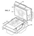
- Fig. 3 is an interior perspective view of the scanner of Fig. 1, showing horizontal and vertical scanner portions;
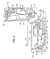
- Fig. 4 is a sectional view of the scanner of Fig. 1, along lines 4-4 of Fig. 3;
- Fig. 5 is a top view of a horizontal mirror basket within a horizontal optics assembly; and
- Fig. 6 is a schematic illustration of the scan volume from the horizontal window of the scanner of Fig. 1, utilizing a prior art scan engine.
- However, it should be noted that the arrangement of pattern mirrors described with reference to the aforementioned drawings can be utilized in a scanner in accordance with the present invention as long as the scanner also utilizes a spinner in accordance with one aspect of the present invention. Thereafter embodiments of the present invention will be described, by way of example, with reference to the accompanying drawings, in which:
- Fig. 7 is schematic of a spinner for use in an optical scanner in accordance with the present invention, arranged to spin around two different axis of rotation;
- Fig. 8 is a schematic representation of a first embodiment of the present invention illustrating one way in which the spinner of Fig. 7 can be powered to spin about said two different axis of rotation;
- Fig. 9 is a schematic representation of a second embodiment of the present invention illustrating another way in which the spinner of Fig. 7 can be powered to spin about said two different axis of rotation;
- Fig. 10 is a schematic representation of a spinner in accordance with another embodiment of the present invention;
- Fig. 11 is a schematic representation of a preferred embodiment of a scanner in accordance with the present invention;
- Fig. 12 is a schematic representation of the substantially hemispherical scan volume produced by an embodiment of the present invention; and
- Fig. 13 is a representation of the scan pattern produced by a scan engine in accordance with the present invention.
- Referring now to Fig. 1, prior art dual aperture
optical scanner 10 includeshorizontal optics assembly 12H andvertical optics assembly 12V, andcontrol circuitry 36 for controlling horizontal andvertical optics assemblies -
Horizontal optics assembly 12H projects a scan pattern through substantiallyhorizontal aperture 34H to scanbar codes 42 located on bottom, leading, trailing and checker side surfaces ofitem 40. It will also scanbar codes 42 on intermediate surfaces including those between the bottom and customer side surfaces. -
Horizontal optics assembly 12H includeslaser 16H, aimingmirror 18H, polygon mirroredspinner 20H, pattern mirrors 22H,routing mirror 26H,collection optic 24H,detector assembly 28H,detection circuitry 30H, andmotor 32H. -
Laser 16H includes one or more laser diodes or other suitable laser sources.Laser 16H may include a laser having a wavelength of 650nm. - Aiming
mirror 18H aims a laser beam fromlaser 16H to polygon mirroredspinner 20H. The laser beam passes through ahole 25H incollection optic 24H (Fig. 4). - Polygon mirrored
spinner 20H directs the laser beam to pattern mirrors 22H. Polygon mirroredspinner 20H also routes collected light tocollection optic 24H. Polygon mirroredspinner 20H preferably includes four facets, but may include other numbers of facets. Facets are grouped into two pairs. Two opposite facets have angles of 74 degrees and 76 degrees from the spinner base. The other pair of opposite facets have angles of 86.5 degrees and 88.5 degrees.Motor 32H rotates polygon mirroredspinner 20H. - Pattern mirrors 22H produce scanning light beams that emanate from substantially
horizontal aperture 34H to form a horizontal scan pattern for readingbar code 42 onitem 40. Pattern mirrors 22H also collect light reflected fromitem 40 and direct it to polygon mirroredspinner 20H. - Collection optic 24H routes collected light from polygon mirrored
spinner 20H torouting mirror 26H. -
Routing mirror 26H routes the collected light todetector assembly 28H. -
Detector assembly 28H focuses, optically filters, and converts collected light into electrical signals. -
Detection circuitry 30H obtains bar code information from the electrical signals.Detection circuitry 30H includes circuitry for digitizing bar code information. -
Vertical optics assembly 12V projects a scan pattern from substantiallyvertical aperture 34V and primarily scans bar codes located on a customer side and top side of an item. Likehorizontal optics assembly 12H,vertical optics assembly 12V scans the leading and trailing sides, as well as intermediate surfaces including those between the bottom and customer side surfaces. However, for simplicity the substantially similar vertical assembly will not be described in detail herein. -
Control circuitry 36 processes the electrical signals fromdetector assemblies 28H andassembly 28V to obtain bar code information.Control circuitry 36 passes the bar code information toPOS terminal 14. -
Control circuitry 36 controls operation oflasers motors Control circuitry 36 may remove power fromlasers motors -
POS terminal 14 receives transaction data, for example, in the form of SKU numbers fromscanner 10 and completes a transaction by finding price data for the SKU numbers in a price-lookup data file. - Turning now to Fig. 2,
scanner 10 is shown in perspective. -
Scanner 10 as illustrated includes anintegral scale 60.Scale 60 includesweigh plate 62, which includes substantiallyhorizontal surface 50 and substantiallyhorizontal aperture 34H.Horizontal window 64H is located withinhorizontal aperture 34H. - Substantially
vertical aperture 34V is located within substantiallyvertical surface 54. Substantiallyvertical window 64V is located within substantiallyvertical aperture 34V. -
Scanner 10 includeshousing 52. Preferably,housing 52 may be easily adapted to fit in atypical checkout counter 56. It is envisioned that substantiallyhorizontal surface 50 be made substantially flush withtop surface 58 ofcounter 56.Scanner 10 is installed withincheckout counter 56 so that substantiallyvertical aperture 34V faces a store employee or other operator. - An illustrated reference X-Y-Z coordinate system determines orientations of pattern mirrors 22H and 22V within
scanner 10 of the present invention. Origin O is defined such that: - X=0 is on the centerline of the scanner;
- Z=0 is on the centerline of the scanner; and
- Y=0 is on the substantially
horizontal surface 50. - Referring now to Figs. 3-4,
horizontal optics assembly 12H andvertical optics assembly 12V are shown in their positions withinhousing 52. -
Horizontal optics assembly 12H andvertical optics assembly 12V each have nearly all of the optical components of a functional bar code scanner.Horizontal optics assembly 12H andvertical optics assembly 12V each have theirown housings circuit boards control circuitry 36 is located inhorizontal optics assembly 12H and signalsvertical optics assembly 12V are brought to controlcircuitry 36 viacables 69. -
Horizontal optics assembly 12H includeshorizontal aperture 35H andwindow 65H. Scale weighplate 62 withhorizontal aperture 34H andwindow 64H are located abovewindow 65H. -
Horizontal optics assembly 12H will scan all label orientations on the bottom and checker sides ofitem 40, as well as certain orientations on the leading and trailing sides. - Optical pathing between
laser 16H and polygon mirroredspinner 20H avoids contacting pattern mirrors 22H along the way.Laser 16H is located on a checker side ofhorizontal optics assembly 12H and polygon mirroredspinner 20H is located on the opposite side.Collection optic 24H is locatedadjacent laser 16H. The laser beam fromlaser 16H passes throughhole 25H incollection optic 24H.Detector assembly 28H is located between collection optic 24H and polygon mirroredspinner 20H. -
Spinners optics assembly 12H, the generation of the front vertical lines requires arcs of light reflected from aspinner 20H on the back side of the optical cavity. - Substantially
vertical aperture 34V is oriented at an acute angle Θ of about 86 degrees from substantiallyhorizontal aperture 34H. Other angular configurations, acute and obtuse, are also anticipated by the present invention. - Operationally,
lasers mirrors holes collection optics polygon spinners horizontal assembly 12H) or forward or rearward (forvertical assembly 12V), depending upon the facet struck. As the facets rotate, the laser beams are scanned in a shallow arc and reflected onto pattern mirrors 22H and 22V. In some cases, primary pattern mirrors reflect the laser beams throughapertures item 40. In other cases, the primary pattern mirrors reflect the laser beams onto secondary mirrors that reflect the laser beams throughapertures item 40. - As
item 40 is moved through the scan zone (abovehorizontal aperture 34H and in front ofvertical aperture 34V), scan lines generated by the laser beams from horizontal andvertical apertures bar code label 42, no matter where it is located onitem 42. A scan line will pass through all or part ofbar code label 40. -
Item 42 scatters light back along the path of the incident laser light. The scattered light passes through horizontal andvertical apertures collection optics Collection optics detector assemblies Detector assemblies pre-video circuitries control circuitry 36. - Referring now to Fig. 5, pattern mirrors 22H are shown in detail. Horizontal pattern mirrors 22H include primary pattern mirrors and secondary pattern mirrors. The primary pattern mirrors receive a laser beam directly from
spinner 20H. The secondary mirrors receive the laser beam from some of the primary pattern mirrors. - The term "front" as applied to mirrors means operator or checker side. The term "rear" as applied to mirrors means the side opposite to the operator or checker side. As illustrated, horizontal pattern mirrors 22H exhibit substantially bilateral symmetry between the leading and trailing sides of
horizontal optics assembly 12H. - The primary pattern mirrors include left rear
diagonal mirror 86, right reardiagonal mirror 88, left frontvertical mirror 78, right frontvertical mirror 80, lefthorizontal mirror 82, righthorizontal mirror 84, leftfront picket mirror 70, rightfront picket mirror 72, left frontdiagonal mirror 102, right frontdiagonal mirror 104, left frontbottom picket mirror 74, and rightfront bottom picket 76. - The secondary pattern mirrors include left rear
diagonal mirror 94, right reardiagonal mirror 96, left frontvertical mirror 90, right frontvertical mirror 92, lefthorizontal mirror 98, and righthorizontal mirror 100. - With reference to Figures 7 to 13,
scanners 200 in accordance with the present invention utilize a two axis scan engine having a dynamicsecond scan axis 202, which increases the scan volume of the scanner 200 (Fig. 12). - In one embodiment this
second axis 202 rotates substantially orthogonally to the spin axis 204 (Fig. 7) of thespinner 200 to essentially rotate the scan volume about this axis (Figures 7 to 10 and 12). - Two approaches are shown in Figure 8 and 9 to describe two different possible methods for rotating the
spinner axis 204 while it is on a revolvingaxis 202. - In the embodiment of Fig. 8 a
motor 206 rotates thegimbal 208 and thespinner 226 is mounted on the gimbal via aspinner shaft 212. Thespinner shaft 212 is arranged to contact (either directly or indirectly) a surface of astationary cylinder 214. Through friction between thecylinder 214 and thespinner shaft 212, or through an arrangement of gears or the like, the rotation of thegimbal 208 causes the rotation of theshaft 212 and consequently the rotation of thespinner 226. Due to the difference in the circumferences of thespinner shaft 212 and thecylinder 214 thespinner 226 is geared to rotate many timed faster than thegimbal 208. - In the embodiment of Fig. 9 a
first motor 206 rotates thegimbal 208, as in Fig. 8; however asecond motor 207 is arranged to rotate thespinner shaft 212 and thus thespinner 226. The first motor (~1,000RPM) is a low speed high torque motor. Thesecond motor 207 is a high speed (~20,000RPM) low torque motor. - In more detail the
optical scanner 200 comprises ascanner housing 218 including ascan window 220. Thescanner 200 also contains alaser light source 222 and adetector 224 for detecting light reflected from a bar code. Thescanner 200 further and most importantly includes aspinner 226 arranged to spin around both a first axis ofrotation 204 and a second axis ofrotation 202. In one embodiment the axes ofrotation rotation 204 is substantially parallel to the plane containing thescan window 220. - The
polygon spinner 226 is externally mirrored as with standard spinners for bar code scanners. In addition thescanner housing 218 can contain pattern mirrors, as described above with reference to Figs 1 to 6, arranged to direct light from thepolygon spinner 226 through thescan window 220 so as to produce scan lines. - As described above, with reference to Fig. 7, in one embodiment the
spinner 226 is mounted on arotating gimbal 208, which is in turn rotated, on thegimbal axis 202, by amotor 206. Thespinner 226 may be rotated, on thespinner axis 204, by a number of different means, as would be apparent to a person skilled in the art, including, but not limited to, the application of magnetic force or compressed air. - Fig. 10 illustrates an embodiment of a scanner in accordance with the present invention in which pattern mirrors 228 arranged to direct overspill light from the polygon spinner 226 (which would not otherwise come directly off of the spinner and out of the scan window) through the
scan window 220, so as to produce scan lines. In a first embodiment the pattern mirrors 228 are a pair of mirrors which spin with the gimbal and thus, in effect, rotate the overspill or excess of each scan line. In a second embodiment thepattern mirror 228 are arranged as an internally mirrored polygon substantially surrounding thespinner 226. Thepolygon 228 is fixed and performs the same function of directing light out of the scan window without spinning with thegimbal 208. - The scanner produces a substantially hemispherical scan volume as illustrated in Figs 10 and 12.
- As can be seen in Fig. 10 the externally mirrored
polygon spinner 226 is arranged to spin in said first axis of rotation (pointing out of the page) and is located substantially within the pattern mirrors 228, which are arranged to spin in said second axis orrotation 202 in the plane of the page. - Fig. 11 illustrates a preferred embodiment of the scanner in accordance with the present invention, in which the optical barcode scanner 240 is comprised of a
scanner housing assembly 242,window assembly 244 and a dualaxis scan engine 246. The scanner also includes a laser light source (not shown), collection optics (not shown), detector assembly (not shown) and decoding electronics (not shown). However, a person skilled in the art would b aware of the best location within thescanner housing assembly 242 for these components. The scan engine is comprised of a mirrored polygon spinner arranged to spin around both the spinner axis ofrotation 204 and the gimbal axis ofrotation 202, as described above. - The
polygon spinner 226 is mounted in a gimbal assembly which in accordance with one embodiment may include a yoke, motor(s), bearings, axle, and spinner. The gimbal assembly is rotated by a motor about the gimbal axis. The polygon spinner is also rotated about its spinner axis by contact or non-contact means as described above. - In this the preferred embodiment of the dual axis scan engine, it can be seen that the polygon spinner reflects the laser light directly out the
scanner window aperture 245. Therefore in this embodiment, pattern mirrors are not required. - In alternative embodiments of the dual axis scan engine, the spinner reflects a portion of the laser light directly out of the
scanner window aperture 245, and the remaining portion of the laser light is reflected off of pattern mirrors prior to being directed out the scanner window aperture. The pattern mirrors may be stationary, or they may be mounted such that they rotate about thesecond axis 202, as described above with reference to Fog. 10. - Finally, the
optical scanner 200 further comprisescontrol circuitry 36 in thescanner housing 218 for obtaining bar code information from electrical signals from the reflectedlight detector 224, as with the scanners as described in Figs 1 to 6. - Scanners in accordance with embodiments of the present invention have a number of advantages. In particular the scan volume is many times that of a conventional single axis scanner (compare Figs 6 & 12), and the readable barcode orientations are increased as well. Also the scan pattern produced by the scanner is considerably more dense than that of prior art scanners, with a greatly increased number of scan lines, which are also more closely packed than with previous scanners, as can be seen in Fig. 13. Also, this approach does not necessarily need pattern mirrors (see Fig 10), which can reduce scanner complexity and production costs significantly. Productivity of the scanner will be significantly increased.
- The foregoing description of the preferred embodiments of the invention has been presented for the purposes of illustration and description. It is not intended to be exhaustive or to limit the invention to the precise form disclosed. Many modifications and variations are possible in light of the above teaching within the scope of the invention as claimed.
Claims (19)
- An optical scanner comprising a scanner housing including a scan window, a laser light source, reflected light detector and a mirrored polygon spinner arranged to spin around both a first axis of rotation and a second axis of rotation.
- An optical scanner as claimed in claim 1, wherein the first and second axis of rotation are substantially orthogonal.
- An optical scanner as claimed in claim 1, wherein the first axis of rotation is directed substantially towards the scan window.
- An optical scanner as claimed in any preceding claim, wherein the polygon spinner is externally mirrored.
- An optical scanner a claimed in any preceding claim , further comprising pattern mirrors arranged to direct light from the polygon spinner through the scan window so as to produce scan lines.
- The optical scanner of claim 1, wherein the spinner is mounted on a rotating gimbal which is in turn rotated by a motor.
- An optical scanner a claimed in any preceding claim, wherein the spinner is rotated through the application of magnetic force.
- An optical scanner a claimed in any preceding claim, wherein the spinner is rotated through the application of compressed air.
- An optical scanner as claimed in claim 6, wherein the spinner is rotated by a motor through slip rings or a comutator.
- An optical scanner as claimed in claim 6, wherein the spinner is mounted on a shaft which is rotated by friction or gears on a stationary cylinder surrounding the motor and spinner.
- An optical scanner a claimed in any preceding claim, further comprising a pattern mirrors arranged to direct light from the polygon spinner through the scan window so as to produce scan lines.
- An optical scanner as claimed in claim 11, wherein the externally mirrored polygon spinner is arranged to spin in said first axis of rotation and is located substantially within said internally mirrored spinner which is arranged to spin in said second axis or rotation.
- An optical scanner as claimed in claim 12, wherein said first axis and second axis of rotation are substantially orthogonal.
- An optical scanner a claimed in any preceding claim, further comprising control circuitry in the scanner housing for obtaining bar code information from electrical signals from the reflected light detector.
- A method of scanning a bar code utilizing an optical scanner comprising a scanner housing including a scan window, a laser light source, reflected light detector and a mirrored polygon spinner arranged to spin around both a first axis of rotation and a second axis of rotation, so as to produce a scan volume, outside of the scan window the method comprising positioning the bar code within the scan volume at any orientation to the scan window.
- A method as claimed in claim 15, wherein the scan volume produced is cone shaped.
- A method as claimed in claim 15, wherein the scan volume produced is substantially hemispherical.
- A method as claimed in claim 15, wherein the gimbal assembly is rotated by a motor about the gimbal axis.
- A method as claimed in claim 15, wherein the polygon spinner is rotated about its spinner axis by a contact or non-contact rotational means.
Applications Claiming Priority (1)
| Application Number | Priority Date | Filing Date | Title |
|---|---|---|---|
| US11/000,022 US7137560B2 (en) | 2004-11-30 | 2004-11-30 | Optical scanner |
Publications (2)
| Publication Number | Publication Date |
|---|---|
| EP1662291A1 true EP1662291A1 (en) | 2006-05-31 |
| EP1662291B1 EP1662291B1 (en) | 2012-02-22 |
Family
ID=35759202
Family Applications (1)
| Application Number | Title | Priority Date | Filing Date |
|---|---|---|---|
| EP05253385A Ceased EP1662291B1 (en) | 2004-11-30 | 2005-06-02 | An optical scanner |
Country Status (3)
| Country | Link |
|---|---|
| US (1) | US7137560B2 (en) |
| EP (1) | EP1662291B1 (en) |
| JP (1) | JP4803646B2 (en) |
Cited By (2)
| Publication number | Priority date | Publication date | Assignee | Title |
|---|---|---|---|---|
| EP2859500A4 (en) * | 2012-06-08 | 2016-03-02 | Datalogic Adc Inc | INTEGRATED DATA READING PLATE DELIMITATING A DATA READING SCAN AREA |
| CN110794382A (en) * | 2019-10-30 | 2020-02-14 | 上海禾赛光电科技有限公司 | Lidar and its detection method |
Families Citing this family (11)
| Publication number | Priority date | Publication date | Assignee | Title |
|---|---|---|---|---|
| US7552874B2 (en) * | 2005-10-31 | 2009-06-30 | Ncr Corporation | Optical scanner |
| EP1909513A1 (en) * | 2006-10-04 | 2008-04-09 | Nec Technologies (UK) Limited | Communication interface between a terminal and a UICC |
| US20090001168A1 (en) * | 2007-06-26 | 2009-01-01 | Hammer Steven J | Barcode scanner including a multi-tasking pattern mirror |
| JP5125409B2 (en) * | 2007-10-26 | 2013-01-23 | セイコーエプソン株式会社 | Image display device |
| CN104154983B (en) | 2008-12-09 | 2017-01-11 | 数据逻辑Adc公司 | Systems and methods for reducing weighing errors associated with partially off-scale items |
| US8556175B2 (en) * | 2009-12-07 | 2013-10-15 | Datalogic ADC, Inc. | Systems and methods for weigh scale perimeter monitoring scanner-scales |
| US8561902B2 (en) | 2009-12-07 | 2013-10-22 | Datalogic ADC, Inc. | Systems and methods for weigh scale perimeter monitoring for scanner-scales |
| US9070007B2 (en) * | 2013-01-11 | 2015-06-30 | Datalogic ADC, Inc. | Adjustable data reader with pivot mount |
| USD723560S1 (en) * | 2013-07-03 | 2015-03-03 | Hand Held Products, Inc. | Scanner |
| US10060785B2 (en) | 2013-10-02 | 2018-08-28 | Datalogic Usa, Inc. | Systems and methods of alternate operation for a scanner-scale having an item overhang detection system |
| USD730901S1 (en) * | 2014-06-24 | 2015-06-02 | Hand Held Products, Inc. | In-counter barcode scanner |
Citations (5)
| Publication number | Priority date | Publication date | Assignee | Title |
|---|---|---|---|---|
| EP0671698A2 (en) * | 1994-02-09 | 1995-09-13 | Opticon Sensors Europe B.V. | Multiple-directional laser scanners |
| US5493388A (en) * | 1993-09-02 | 1996-02-20 | Nissan Motor Co., Ltd. | Distance measuring device |
| US5886336A (en) * | 1996-12-12 | 1999-03-23 | Ncr Corporation | Multiside coverage optical scanner |
| US20040056099A1 (en) * | 2001-04-03 | 2004-03-25 | Symbol Technologies, Inc. | Two window optical scanner |
| US20040217175A1 (en) * | 1992-07-14 | 2004-11-04 | Psc Scanning, Inc. | Multiple plane scanning system for data reading applications |
Family Cites Families (9)
| Publication number | Priority date | Publication date | Assignee | Title |
|---|---|---|---|---|
| DE2848325A1 (en) * | 1978-11-08 | 1980-05-22 | Philips Patentverwaltung | THERMAL IMAGING DEVICE FOR DETECTING AND DETECTING A THERMAL TARGET |
| US4973838A (en) * | 1981-04-24 | 1990-11-27 | The United States Of America As Represented By The Secretary Of The Navy | Pulsed laser beam deviation apparatus |
| JP2740687B2 (en) * | 1990-06-08 | 1998-04-15 | 株式会社日本自動車部品総合研究所 | Optical scanning device |
| US5555125A (en) * | 1993-01-11 | 1996-09-10 | Opticon Sensors Europe B.V. | Optical scanner |
| JPH0720812A (en) * | 1993-07-02 | 1995-01-24 | Sega Enterp Ltd | Polar coordinate scanning spherical projector |
| US5767501A (en) * | 1993-11-24 | 1998-06-16 | Metrologic Instruments, Inc. | Mass-balanced automatic hand-supportable laser projection scanner for fatigue-free omnidirectional scanning of bar code symbols |
| JP3333054B2 (en) * | 1994-10-20 | 2002-10-07 | オリンパス光学工業株式会社 | Laser distance measuring device |
| EP0753823A1 (en) * | 1995-07-05 | 1997-01-15 | Opticon Sensors Europe B.V. | Optical scanner for generating scanning lines on all sides of an object |
| JP3881792B2 (en) * | 1998-10-21 | 2007-02-14 | 富士通株式会社 | Optical scanning device, code reading device, and bar code reading device |
-
2004
- 2004-11-30 US US11/000,022 patent/US7137560B2/en not_active Expired - Fee Related
-
2005
- 2005-06-02 EP EP05253385A patent/EP1662291B1/en not_active Ceased
- 2005-07-14 JP JP2005205044A patent/JP4803646B2/en not_active Expired - Fee Related
Patent Citations (5)
| Publication number | Priority date | Publication date | Assignee | Title |
|---|---|---|---|---|
| US20040217175A1 (en) * | 1992-07-14 | 2004-11-04 | Psc Scanning, Inc. | Multiple plane scanning system for data reading applications |
| US5493388A (en) * | 1993-09-02 | 1996-02-20 | Nissan Motor Co., Ltd. | Distance measuring device |
| EP0671698A2 (en) * | 1994-02-09 | 1995-09-13 | Opticon Sensors Europe B.V. | Multiple-directional laser scanners |
| US5886336A (en) * | 1996-12-12 | 1999-03-23 | Ncr Corporation | Multiside coverage optical scanner |
| US20040056099A1 (en) * | 2001-04-03 | 2004-03-25 | Symbol Technologies, Inc. | Two window optical scanner |
Cited By (2)
| Publication number | Priority date | Publication date | Assignee | Title |
|---|---|---|---|---|
| EP2859500A4 (en) * | 2012-06-08 | 2016-03-02 | Datalogic Adc Inc | INTEGRATED DATA READING PLATE DELIMITATING A DATA READING SCAN AREA |
| CN110794382A (en) * | 2019-10-30 | 2020-02-14 | 上海禾赛光电科技有限公司 | Lidar and its detection method |
Also Published As
| Publication number | Publication date |
|---|---|
| US7137560B2 (en) | 2006-11-21 |
| EP1662291B1 (en) | 2012-02-22 |
| JP4803646B2 (en) | 2011-10-26 |
| US20060113394A1 (en) | 2006-06-01 |
| JP2006154738A (en) | 2006-06-15 |
Similar Documents
| Publication | Publication Date | Title |
|---|---|---|
| EP1662291B1 (en) | An optical scanner | |
| US6536668B1 (en) | Dual aperture optical scanner | |
| EP0348232B1 (en) | Optical beam scanner for reading bar-codes | |
| USRE42651E1 (en) | Optical scanner having enhanced item side coverage | |
| JP3834115B2 (en) | Optical scanner | |
| JPH0424776A (en) | Nondirectional laser scanner | |
| US6045046A (en) | Full coverage barcode scanner | |
| US5559319A (en) | Oscillation bar code reader | |
| US5149949A (en) | Optical scanner with counterrotating reflector elements | |
| EP0319237A2 (en) | Light-scanning reader | |
| EP0396485B1 (en) | Bar code scanner with a large depth of field | |
| US5179271A (en) | Compact optical scan pattern generator for bar code reading systems | |
| JPH06333080A (en) | Optical barcode scanner | |
| WO1994001835A1 (en) | Multiple plane scanning system for data reading applications | |
| EP1526475A2 (en) | Optical scanner having enhanced item side coverage | |
| JPH0823629B2 (en) | Optical reader | |
| JPH11112097A (en) | Light source module and optical scanning device | |
| US20070095919A1 (en) | Optical scanner | |
| US6543694B1 (en) | Extended coverage barcode scanner | |
| JPH08335243A (en) | Barcode scanner | |
| US6237851B1 (en) | Dual mode barcode scanner | |
| US7051939B2 (en) | Bar code scanner with laser beam oscillator | |
| US7264167B2 (en) | Optical scanner having micro-electro-mechanical systems mirror array and associated method | |
| US6905070B1 (en) | Bar code scanner | |
| EP0533383A2 (en) | Optical scanner apparatus |
Legal Events
| Date | Code | Title | Description |
|---|---|---|---|
| PUAI | Public reference made under article 153(3) epc to a published international application that has entered the european phase |
Free format text: ORIGINAL CODE: 0009012 |
|
| AK | Designated contracting states |
Kind code of ref document: A1 Designated state(s): AT BE BG CH CY CZ DE DK EE ES FI FR GB GR HU IE IS IT LI LT LU MC NL PL PT RO SE SI SK TR |
|
| AX | Request for extension of the european patent |
Extension state: AL BA HR LV MK YU |
|
| 17P | Request for examination filed |
Effective date: 20061130 |
|
| AKX | Designation fees paid |
Designated state(s): DE FR GB |
|
| 17Q | First examination report despatched |
Effective date: 20071119 |
|
| RAP1 | Party data changed (applicant data changed or rights of an application transferred) |
Owner name: NCR INTERNATIONAL, INC. |
|
| GRAP | Despatch of communication of intention to grant a patent |
Free format text: ORIGINAL CODE: EPIDOSNIGR1 |
|
| GRAS | Grant fee paid |
Free format text: ORIGINAL CODE: EPIDOSNIGR3 |
|
| GRAA | (expected) grant |
Free format text: ORIGINAL CODE: 0009210 |
|
| AK | Designated contracting states |
Kind code of ref document: B1 Designated state(s): DE FR GB |
|
| REG | Reference to a national code |
Ref country code: GB Ref legal event code: FG4D |
|
| REG | Reference to a national code |
Ref country code: DE Ref legal event code: R084 Ref document number: 602005032765 Country of ref document: DE |
|
| REG | Reference to a national code |
Ref country code: GB Ref legal event code: 746 Effective date: 20120312 |
|
| REG | Reference to a national code |
Ref country code: DE Ref legal event code: R096 Ref document number: 602005032765 Country of ref document: DE Effective date: 20120419 |
|
| REG | Reference to a national code |
Ref country code: DE Ref legal event code: R084 Ref document number: 602005032765 Country of ref document: DE Effective date: 20120227 |
|
| PLBE | No opposition filed within time limit |
Free format text: ORIGINAL CODE: 0009261 |
|
| STAA | Information on the status of an ep patent application or granted ep patent |
Free format text: STATUS: NO OPPOSITION FILED WITHIN TIME LIMIT |
|
| 26N | No opposition filed |
Effective date: 20121123 |
|
| REG | Reference to a national code |
Ref country code: DE Ref legal event code: R097 Ref document number: 602005032765 Country of ref document: DE Effective date: 20121123 |
|
| REG | Reference to a national code |
Ref country code: FR Ref legal event code: PLFP Year of fee payment: 12 |
|
| REG | Reference to a national code |
Ref country code: FR Ref legal event code: PLFP Year of fee payment: 13 |
|
| REG | Reference to a national code |
Ref country code: FR Ref legal event code: PLFP Year of fee payment: 14 |
|
| PGFP | Annual fee paid to national office [announced via postgrant information from national office to epo] |
Ref country code: FR Payment date: 20180626 Year of fee payment: 14 |
|
| PGFP | Annual fee paid to national office [announced via postgrant information from national office to epo] |
Ref country code: DE Payment date: 20180627 Year of fee payment: 14 Ref country code: GB Payment date: 20180627 Year of fee payment: 14 |
|
| REG | Reference to a national code |
Ref country code: DE Ref legal event code: R119 Ref document number: 602005032765 Country of ref document: DE |
|
| GBPC | Gb: european patent ceased through non-payment of renewal fee |
Effective date: 20190602 |
|
| PG25 | Lapsed in a contracting state [announced via postgrant information from national office to epo] |
Ref country code: DE Free format text: LAPSE BECAUSE OF NON-PAYMENT OF DUE FEES Effective date: 20200101 Ref country code: GB Free format text: LAPSE BECAUSE OF NON-PAYMENT OF DUE FEES Effective date: 20190602 |
|
| PG25 | Lapsed in a contracting state [announced via postgrant information from national office to epo] |
Ref country code: FR Free format text: LAPSE BECAUSE OF NON-PAYMENT OF DUE FEES Effective date: 20190630 |