EP1662203A1 - Combustor - Google Patents
Combustor Download PDFInfo
- Publication number
- EP1662203A1 EP1662203A1 EP05256724A EP05256724A EP1662203A1 EP 1662203 A1 EP1662203 A1 EP 1662203A1 EP 05256724 A EP05256724 A EP 05256724A EP 05256724 A EP05256724 A EP 05256724A EP 1662203 A1 EP1662203 A1 EP 1662203A1
- Authority
- EP
- European Patent Office
- Prior art keywords
- casing
- rim
- aperture
- reinforcing member
- combustor
- Prior art date
- Legal status (The legal status is an assumption and is not a legal conclusion. Google has not performed a legal analysis and makes no representation as to the accuracy of the status listed.)
- Granted
Links
Images


Classifications
-
- F—MECHANICAL ENGINEERING; LIGHTING; HEATING; WEAPONS; BLASTING
- F23—COMBUSTION APPARATUS; COMBUSTION PROCESSES
- F23R—GENERATING COMBUSTION PRODUCTS OF HIGH PRESSURE OR HIGH VELOCITY, e.g. GAS-TURBINE COMBUSTION CHAMBERS
- F23R3/00—Continuous combustion chambers using liquid or gaseous fuel
- F23R3/42—Continuous combustion chambers using liquid or gaseous fuel characterised by the arrangement or form of the flame tubes or combustion chambers
- F23R3/60—Support structures; Attaching or mounting means
-
- F—MECHANICAL ENGINEERING; LIGHTING; HEATING; WEAPONS; BLASTING
- F23—COMBUSTION APPARATUS; COMBUSTION PROCESSES
- F23R—GENERATING COMBUSTION PRODUCTS OF HIGH PRESSURE OR HIGH VELOCITY, e.g. GAS-TURBINE COMBUSTION CHAMBERS
- F23R3/00—Continuous combustion chambers using liquid or gaseous fuel
- F23R3/42—Continuous combustion chambers using liquid or gaseous fuel characterised by the arrangement or form of the flame tubes or combustion chambers
- F23R3/50—Combustion chambers comprising an annular flame tube within an annular casing
Definitions
- This invention relates to a casing. More particularly this invention relates to a casing for a combustion chamber of a gas turbine engine.
- a ducted fan gas turbine engine generally comprises, in axial flow series, an air intake, a propulsive fan, an intermediate pressure compressor, a high pressure compressor, combustion equipment, a high pressure turbine, an intermediate pressure turbine, a low pressure turbine and an exhaust nozzle.
- Combustors and combustor casings can have a large number of apertures.
- the apertures allow access for components such as fuel manifolds, probes and ignitors which, partly due to the high temperatures within the combustion chamber, must necessarily by positioned externally of the combustion chamber outer casing.
- the apertures must be reinforced against stresses. Traditionally this is achieved by reinforcing the rim of the aperture with some of the material from which the casing is formed.
- the casing and rim reinforcement are typically formed by casting or forging.
- a forging process a volume of material is heated shaped by two or more dies. The material undergoes plastic deformation and conforms to the shape of the die. The volume of the material does not alter significantly in the forging process.
- a volume of material equal to the size of the aperture must formed. In some areas this volume of material may be used to form the reinforcing rims of the apertures, in other areas the volume of material is dispersed around the casing and must subsequently be removed.
- Gas turbines have weight and cost considerations that must be addressed. Where a turbine provides thrust for a transport device such as a ship or plane reducing the weight of the engine can have a beneficial effect on the efficiency of the transport device and can lead to a reduction in the fuel consumption.
- a combustion casing for use in a gas turbine, the casing having an aperture extending therethrough, characterised in that the aperture has a reinforcing member extending across and dividing the aperture.
- the aperture has a rim extending around the periphery of the aperture and preferably the rim is raised from a substantially planar area of the casing.
- the reinforcing member is integral with the rim.
- the rim and the reinforcing member are formed simultaneously by casting, sintering or forging.
- the rim is integral with the casing.
- the rim and the casing are formed simultaneously by casting, sintering or forging.
- the rim may be subject to a stress field and preferably the reinforcing member is orientated so as to align with the direction of maximum stress field.
- the reinforcing member may be a single or plural bar that may be straight, curved or serpentine.
- casing in this specification includes hoods, cowling, sheets, combustors, combustor casings and other components having similar functionality to the above.
- Figure 1 depicts annular combustion equipment for a gas turbine engine.
- the combustion equipment consists of an annular combustion inner casing 20, and a coaxial annular combustion outer casing 22.
- the combustion chamber 24 is coaxial with and positioned between the inner casing 20 and the outer casing 22.
- the combustion chamber 24 is defined by an outer combustor wall 26 and an inner combustor wall 28, the internal volume being adapted to allow multiple combustion zones.
- a series of regularly spaced fuel injectors 30 extend through a bulkhead 32 that forms one wall of the combustion chamber.
- the fuel injectors mix air with fuel and eject it into the combustion chamber as a finely dispersed mixture.
- Fuel is supplied to the injectors via a conduit that extends through apertures in the combustion outer casing 22. Also extending through apertures in the combustion chamber outer casing are igniters that ignite the finely dispersed air and fuel mixture injected into the combustion chamber by the fuel injectors.
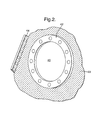
- Figure 2 depicts an aperture 40 in the combustion outer casing that has been formed by a forging process.
- the aperture has a rim 42 that is raised from the local surface of the combustion outer casing 22.
- a flange 44 is provided on the combustion outer casing for connection with a high pressure compressor housing.
- the material of the combustion outer casing is a high temperature nickel alloy or steel.
- the rim reinforces the casing against stresses that are created by the presence of the apertures and movement induced by pressure fluctuations in the combustor.
- the volume of material within the rim is typically equal to that lost in the formation of the aperture.
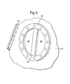
- Figure 3 depicts a reinforcing member for an aperture according to the present invention.
- the reinforcing member 50 extends across the aperture and is formed during the forging process.
- the member is aligned to align with the direction of maximum stress field.
- the stress fields may be determined either empirically or by routine calculation.
- a reinforcing member of this type uses significantly less volume of material than that of the prior art to achieve an equal or better reinforcement.
- the overall volume of material for the casing is reduced. Where a large number of apertures are provided, as in the combustor outer casing, it can result in lower forging and machining costs and a significant cost saving in the amount of material required as well as a reduction in the weight of the component.
- Figure 4 is a schematic of a gas turbine engine incorporating a combustor with a casing of the invention.
- the gas turbine engine has a fan 102, an intermediate compressor 104, a high pressure compressor 106, an annular combustor 108, a high pressure turbine 110, an intermediate pressure turbine 112 and a low pressure turbine 114
Landscapes
- Engineering & Computer Science (AREA)
- Chemical & Material Sciences (AREA)
- Combustion & Propulsion (AREA)
- Mechanical Engineering (AREA)
- General Engineering & Computer Science (AREA)
- Turbine Rotor Nozzle Sealing (AREA)
- Structures Of Non-Positive Displacement Pumps (AREA)
Abstract
Description
- This invention relates to a casing. More particularly this invention relates to a casing for a combustion chamber of a gas turbine engine.
- A ducted fan gas turbine engine generally comprises, in axial flow series, an air intake, a propulsive fan, an intermediate pressure compressor, a high pressure compressor, combustion equipment, a high pressure turbine, an intermediate pressure turbine, a low pressure turbine and an exhaust nozzle.
- The structure and operation of all these components is generally well known and consequently, with the exception of the combustion equipment, will not be described in great detail in this specification.
- Combustors and combustor casings can have a large number of apertures. The apertures allow access for components such as fuel manifolds, probes and ignitors which, partly due to the high temperatures within the combustion chamber, must necessarily by positioned externally of the combustion chamber outer casing.
- The apertures must be reinforced against stresses. Traditionally this is achieved by reinforcing the rim of the aperture with some of the material from which the casing is formed.
- The casing and rim reinforcement are typically formed by casting or forging. In a forging process a volume of material is heated shaped by two or more dies. The material undergoes plastic deformation and conforms to the shape of the die. The volume of the material does not alter significantly in the forging process.
- Where provision for apertures are formed as part of the forging process a volume of material equal to the size of the aperture must formed. In some areas this volume of material may be used to form the reinforcing rims of the apertures, in other areas the volume of material is dispersed around the casing and must subsequently be removed.
- Where the aperture requires reinforcement greater than the casing thickness an additional volume of material must be added in the forging process.
- Gas turbines have weight and cost considerations that must be addressed. Where a turbine provides thrust for a transport device such as a ship or plane reducing the weight of the engine can have a beneficial effect on the efficiency of the transport device and can lead to a reduction in the fuel consumption.
- It is an object of the present invention to seek to provide an improved reinforced aperture.
- According to the present invention there is provided a combustion casing for use in a gas turbine, the casing having an aperture extending therethrough, characterised in that the aperture has a reinforcing member extending across and dividing the aperture.
- Preferably the aperture has a rim extending around the periphery of the aperture and preferably the rim is raised from a substantially planar area of the casing.
- Preferably the reinforcing member is integral with the rim.
- Preferably the rim and the reinforcing member are formed simultaneously by casting, sintering or forging.
- Preferably the rim is integral with the casing.
- Preferably the rim and the casing are formed simultaneously by casting, sintering or forging.
- The rim may be subject to a stress field and preferably the reinforcing member is orientated so as to align with the direction of maximum stress field. The reinforcing member may be a single or plural bar that may be straight, curved or serpentine.
- The term "casing" in this specification includes hoods, cowling, sheets, combustors, combustor casings and other components having similar functionality to the above.
- The present invention will now be described, by way of example only, with reference to the accompanying drawings in which:
- Figure 1 depicts an annular combustion chamber
- Figure 2 is a conventional aperture in the combustion chamber casing
- Figure 3 is an aperture according to the present invention.
- Figure 4 depicts a gas turbine engine having a combustor with a casing in accordance with the present invention.
- Figure 1 depicts annular combustion equipment for a gas turbine engine. The combustion equipment consists of an annular combustion
inner casing 20, and a coaxial annular combustionouter casing 22. Thecombustion chamber 24 is coaxial with and positioned between theinner casing 20 and theouter casing 22. - The
combustion chamber 24 is defined by anouter combustor wall 26 and aninner combustor wall 28, the internal volume being adapted to allow multiple combustion zones. - A series of regularly spaced
fuel injectors 30 extend through abulkhead 32 that forms one wall of the combustion chamber. The fuel injectors mix air with fuel and eject it into the combustion chamber as a finely dispersed mixture. - Fuel is supplied to the injectors via a conduit that extends through apertures in the combustion
outer casing 22. Also extending through apertures in the combustion chamber outer casing are igniters that ignite the finely dispersed air and fuel mixture injected into the combustion chamber by the fuel injectors. - Figure 2 depicts an
aperture 40 in the combustion outer casing that has been formed by a forging process. The aperture has arim 42 that is raised from the local surface of the combustionouter casing 22. Aflange 44 is provided on the combustion outer casing for connection with a high pressure compressor housing. - The material of the combustion outer casing is a high temperature nickel alloy or steel. The rim reinforces the casing against stresses that are created by the presence of the apertures and movement induced by pressure fluctuations in the combustor.
- To adequately overcome hoop stresses the volume of material within the rim is typically equal to that lost in the formation of the aperture.
- Figure 3 depicts a reinforcing member for an aperture according to the present invention. The reinforcing
member 50 extends across the aperture and is formed during the forging process. The member is aligned to align with the direction of maximum stress field. The stress fields may be determined either empirically or by routine calculation. - A reinforcing member of this type uses significantly less volume of material than that of the prior art to achieve an equal or better reinforcement. The overall volume of material for the casing is reduced. Where a large number of apertures are provided, as in the combustor outer casing, it can result in lower forging and machining costs and a significant cost saving in the amount of material required as well as a reduction in the weight of the component.
- Where reinforcement is achieved through the provision of a reinforcement member of the present invention it is possible to increase the size of the aperture without loss of functionality due to detrimental effects caused by stresses on the component. The cost and weight savings offered by the present invention are thereby further enhanced.
- Figure 4 is a schematic of a gas turbine engine incorporating a combustor with a casing of the invention. The gas turbine engine has a
fan 102, anintermediate compressor 104, a high pressure compressor 106, anannular combustor 108, ahigh pressure turbine 110, anintermediate pressure turbine 112 and alow pressure turbine 114 - It will be appreciated that other embodiments may be apparent to the skilled reader without departing from the inventive concept of the present invention.
- Each feature described herein may be incorporated into the claims either independently or in combination with any other feature.
Claims (10)
- A combustion casing (26) for use in a gas turbine, the casing having an aperture (40) extending therethrough, characterised in that the aperture has a reinforcing member (50) extending across and dividing the aperture.
- A casing according to Claim 1, wherein the casing is annular.
- A casing according to Claim 1, wherein the aperture has a rim (42) extending around its periphery.
- A casing according to Claim 2, wherein the rim is raised from a substantially planar area of the casing.
- A casing according to Claim 2 or Claim 3, wherein the reinforcing member (50) is integral with the rim.
- A casing according to any one of Claim 2 to Claim 4, wherein the rim and the reinforcing member are formed simultaneously by casting, sintering or forging.
- A casing according to any one of Claim 2 to Claim 5, wherein the rim is integral with the casing.
- A casing according to any one of Claim 2 to Claim 6, wherein the rim and the casing are formed simultaneously by casting, sintering or forging.
- A casing according to any one of Claim 2 to Claim 7, wherein the rim is subject to a stress field, the reinforcing member being orientated so as to align with the direction of maximum stress field.
- A gas turbine engine incorporating a combustor casing as claimed in any one of the preceding claims.
Applications Claiming Priority (1)
| Application Number | Priority Date | Filing Date | Title |
|---|---|---|---|
| GBGB0426214.3A GB0426214D0 (en) | 2004-11-30 | 2004-11-30 | Combustor |
Publications (2)
| Publication Number | Publication Date |
|---|---|
| EP1662203A1 true EP1662203A1 (en) | 2006-05-31 |
| EP1662203B1 EP1662203B1 (en) | 2008-08-06 |
Family
ID=33561542
Family Applications (1)
| Application Number | Title | Priority Date | Filing Date |
|---|---|---|---|
| EP05256724A Expired - Lifetime EP1662203B1 (en) | 2004-11-30 | 2005-10-31 | Combustor |
Country Status (4)
| Country | Link |
|---|---|
| US (1) | US20060213203A1 (en) |
| EP (1) | EP1662203B1 (en) |
| DE (1) | DE602005008688D1 (en) |
| GB (1) | GB0426214D0 (en) |
Families Citing this family (1)
| Publication number | Priority date | Publication date | Assignee | Title |
|---|---|---|---|---|
| US9181812B1 (en) * | 2009-05-05 | 2015-11-10 | Majed Toqan | Can-annular combustor with premixed tangential fuel-air nozzles for use on gas turbine engines |
Citations (5)
| Publication number | Priority date | Publication date | Assignee | Title |
|---|---|---|---|---|
| US2488911A (en) * | 1946-11-09 | 1949-11-22 | Surface Combustion Corp | Combustion apparatus for use with turbines |
| US2513325A (en) * | 1946-08-29 | 1950-07-04 | Westinghouse Electric Corp | Combustion apparatus |
| US3019605A (en) * | 1956-11-21 | 1962-02-06 | Rolls Royce | Combustion apparatus of gas turbine engines with means controlling air flow conditions in the combustion apparatus |
| JPS60194234A (en) * | 1984-03-16 | 1985-10-02 | Hitachi Ltd | gas turbine combustor |
| EP1329669A2 (en) * | 2002-01-16 | 2003-07-23 | General Electric Company | Method and apparatus for relieving stress in a combustion case in a gas turbine engine |
Family Cites Families (3)
| Publication number | Priority date | Publication date | Assignee | Title |
|---|---|---|---|---|
| US2543755A (en) * | 1946-07-25 | 1951-03-06 | Westinghouse Electric Corp | Air inlet opening arrangement for combustion chambers |
| US2782597A (en) * | 1952-03-15 | 1957-02-26 | Gen Electric | Combustion chamber having improved air inlet means |
| US2952126A (en) * | 1955-05-10 | 1960-09-13 | Midland Ross Corp | Combustion unit for supplying hot gas for jet aircraft |
-
2004
- 2004-11-30 GB GBGB0426214.3A patent/GB0426214D0/en not_active Ceased
-
2005
- 2005-10-31 DE DE602005008688T patent/DE602005008688D1/en not_active Expired - Lifetime
- 2005-10-31 EP EP05256724A patent/EP1662203B1/en not_active Expired - Lifetime
- 2005-11-01 US US11/262,771 patent/US20060213203A1/en not_active Abandoned
Patent Citations (5)
| Publication number | Priority date | Publication date | Assignee | Title |
|---|---|---|---|---|
| US2513325A (en) * | 1946-08-29 | 1950-07-04 | Westinghouse Electric Corp | Combustion apparatus |
| US2488911A (en) * | 1946-11-09 | 1949-11-22 | Surface Combustion Corp | Combustion apparatus for use with turbines |
| US3019605A (en) * | 1956-11-21 | 1962-02-06 | Rolls Royce | Combustion apparatus of gas turbine engines with means controlling air flow conditions in the combustion apparatus |
| JPS60194234A (en) * | 1984-03-16 | 1985-10-02 | Hitachi Ltd | gas turbine combustor |
| EP1329669A2 (en) * | 2002-01-16 | 2003-07-23 | General Electric Company | Method and apparatus for relieving stress in a combustion case in a gas turbine engine |
Non-Patent Citations (1)
| Title |
|---|
| PATENT ABSTRACTS OF JAPAN vol. 010, no. 044 (M - 455) 21 February 1986 (1986-02-21) * |
Also Published As
| Publication number | Publication date |
|---|---|
| DE602005008688D1 (en) | 2008-09-18 |
| US20060213203A1 (en) | 2006-09-28 |
| EP1662203B1 (en) | 2008-08-06 |
| GB0426214D0 (en) | 2004-12-29 |
Similar Documents
| Publication | Publication Date | Title |
|---|---|---|
| US7805944B2 (en) | Combustion chamber air inlet | |
| EP1340941B1 (en) | Corrugated cowl for combustor of a gas turbine engine and method for configuring the same | |
| US7882696B2 (en) | Integrated support and mixer for turbo machinery | |
| US11156359B2 (en) | Combustor liner panel end rail with diffused interface passage for a gas turbine engine combustor | |
| US8893382B2 (en) | Combustion system and method of assembling the same | |
| EP3315866B1 (en) | Combustor assembly with mounted auxiliary component | |
| US9103219B2 (en) | CMC turbine nozzle adapted to support a metallic turbine internal casing by an axial contact | |
| US9897316B2 (en) | Combustion chamber for a turbine engine | |
| EP2844880B1 (en) | Supporting structure for a gas turbine engine | |
| EP1558875B1 (en) | Liner for a gas turbine engine combustor having trapped vortex cavity | |
| EP2236750B1 (en) | An impingement cooling arrangement for a gas turbine engine | |
| US10060631B2 (en) | Hybrid diffuser case for a gas turbine engine combustor | |
| US10168051B2 (en) | Combustor assembly for a turbine engine | |
| EP3865405B1 (en) | Nacelle for gas turbine engine and aircraft comprising the same | |
| US20110283711A1 (en) | Gas turbine component and a gas turbine engine comprising the component | |
| US8511971B2 (en) | One-piece compressor and turbine containment system | |
| EP2870364B1 (en) | Supporting structure for a gas turbine engine | |
| US20190072276A1 (en) | Float wall combustor panels having heat transfer augmentation | |
| EP1662203A1 (en) | Combustor | |
| US7909569B2 (en) | Turbine support case and method of manufacturing | |
| US12253048B2 (en) | Fastening of an exhaust cone in a turbomachine turbine | |
| EP4163499A1 (en) | Diffuser and deswirl system with integral tangential on-board injector for engine | |
| EP4474706B1 (en) | Combustor assembly for a gas turbine engine | |
| EP3032038B1 (en) | Pre-diffuser of a gas turbine engine, gas turbine engine and method of forming a pre-diffuser of a gas turbine engine | |
| US11614234B2 (en) | Turbine engine combustion chamber |
Legal Events
| Date | Code | Title | Description |
|---|---|---|---|
| PUAI | Public reference made under article 153(3) epc to a published international application that has entered the european phase |
Free format text: ORIGINAL CODE: 0009012 |
|
| AK | Designated contracting states |
Kind code of ref document: A1 Designated state(s): AT BE BG CH CY CZ DE DK EE ES FI FR GB GR HU IE IS IT LI LT LU LV MC NL PL PT RO SE SI SK TR |
|
| AX | Request for extension of the european patent |
Extension state: AL BA HR MK YU |
|
| 17P | Request for examination filed |
Effective date: 20060506 |
|
| 17Q | First examination report despatched |
Effective date: 20060711 |
|
| AKX | Designation fees paid |
Designated state(s): DE FR GB |
|
| GRAP | Despatch of communication of intention to grant a patent |
Free format text: ORIGINAL CODE: EPIDOSNIGR1 |
|
| GRAS | Grant fee paid |
Free format text: ORIGINAL CODE: EPIDOSNIGR3 |
|
| GRAA | (expected) grant |
Free format text: ORIGINAL CODE: 0009210 |
|
| AK | Designated contracting states |
Kind code of ref document: B1 Designated state(s): DE FR GB |
|
| REG | Reference to a national code |
Ref country code: GB Ref legal event code: FG4D |
|
| REF | Corresponds to: |
Ref document number: 602005008688 Country of ref document: DE Date of ref document: 20080918 Kind code of ref document: P |
|
| PLBE | No opposition filed within time limit |
Free format text: ORIGINAL CODE: 0009261 |
|
| STAA | Information on the status of an ep patent application or granted ep patent |
Free format text: STATUS: NO OPPOSITION FILED WITHIN TIME LIMIT |
|
| 26N | No opposition filed |
Effective date: 20090507 |
|
| PGFP | Annual fee paid to national office [announced via postgrant information from national office to epo] |
Ref country code: FR Payment date: 20101104 Year of fee payment: 6 |
|
| PGFP | Annual fee paid to national office [announced via postgrant information from national office to epo] |
Ref country code: DE Payment date: 20101022 Year of fee payment: 6 |
|
| PGFP | Annual fee paid to national office [announced via postgrant information from national office to epo] |
Ref country code: GB Payment date: 20101021 Year of fee payment: 6 |
|
| GBPC | Gb: european patent ceased through non-payment of renewal fee |
Effective date: 20111031 |
|
| REG | Reference to a national code |
Ref country code: FR Ref legal event code: ST Effective date: 20120629 |
|
| PG25 | Lapsed in a contracting state [announced via postgrant information from national office to epo] |
Ref country code: DE Free format text: LAPSE BECAUSE OF NON-PAYMENT OF DUE FEES Effective date: 20120501 |
|
| REG | Reference to a national code |
Ref country code: DE Ref legal event code: R119 Ref document number: 602005008688 Country of ref document: DE Effective date: 20120501 |
|
| PG25 | Lapsed in a contracting state [announced via postgrant information from national office to epo] |
Ref country code: FR Free format text: LAPSE BECAUSE OF NON-PAYMENT OF DUE FEES Effective date: 20111102 Ref country code: GB Free format text: LAPSE BECAUSE OF NON-PAYMENT OF DUE FEES Effective date: 20111031 |