EP1662176A2 - Linear motion device - Google Patents
Linear motion device Download PDFInfo
- Publication number
- EP1662176A2 EP1662176A2 EP05026006A EP05026006A EP1662176A2 EP 1662176 A2 EP1662176 A2 EP 1662176A2 EP 05026006 A EP05026006 A EP 05026006A EP 05026006 A EP05026006 A EP 05026006A EP 1662176 A2 EP1662176 A2 EP 1662176A2
- Authority
- EP
- European Patent Office
- Prior art keywords
- rolling
- rolling element
- passage
- linear motion
- motion device
- Prior art date
- Legal status (The legal status is an assumption and is not a legal conclusion. Google has not performed a legal analysis and makes no representation as to the accuracy of the status listed.)
- Withdrawn
Links
- 238000005096 rolling process Methods 0.000 claims abstract description 102
- 239000011347 resin Substances 0.000 claims description 21
- 229920005989 resin Polymers 0.000 claims description 21
- 239000000463 material Substances 0.000 claims description 20
- 238000005452 bending Methods 0.000 claims description 12
- 238000010521 absorption reaction Methods 0.000 claims description 7
- 229920006122 polyamide resin Polymers 0.000 claims description 6
- 239000004677 Nylon Substances 0.000 description 8
- 229920001778 nylon Polymers 0.000 description 8
- 229930040373 Paraformaldehyde Natural products 0.000 description 6
- 229920006324 polyoxymethylene Polymers 0.000 description 6
- 239000004696 Poly ether ether ketone Substances 0.000 description 5
- 239000004734 Polyphenylene sulfide Substances 0.000 description 5
- 229920002530 polyetherether ketone Polymers 0.000 description 5
- 229920000069 polyphenylene sulfide Polymers 0.000 description 5
- XLYOFNOQVPJJNP-UHFFFAOYSA-N water Substances O XLYOFNOQVPJJNP-UHFFFAOYSA-N 0.000 description 4
- 238000001746 injection moulding Methods 0.000 description 2
- -1 polyoxymethylene Polymers 0.000 description 2
- 239000004953 Aliphatic polyamide Substances 0.000 description 1
- 229920002302 Nylon 6,6 Polymers 0.000 description 1
- 229920003231 aliphatic polyamide Polymers 0.000 description 1
- 239000003795 chemical substances by application Substances 0.000 description 1
- 230000001747 exhibiting effect Effects 0.000 description 1
- 238000004519 manufacturing process Methods 0.000 description 1
- 239000003973 paint Substances 0.000 description 1
- 239000012744 reinforcing agent Substances 0.000 description 1
Images

Classifications
-
- F—MECHANICAL ENGINEERING; LIGHTING; HEATING; WEAPONS; BLASTING
- F16—ENGINEERING ELEMENTS AND UNITS; GENERAL MEASURES FOR PRODUCING AND MAINTAINING EFFECTIVE FUNCTIONING OF MACHINES OR INSTALLATIONS; THERMAL INSULATION IN GENERAL
- F16H—GEARING
- F16H25/00—Gearings comprising primarily only cams, cam-followers and screw-and-nut mechanisms
- F16H25/18—Gearings comprising primarily only cams, cam-followers and screw-and-nut mechanisms for conveying or interconverting oscillating or reciprocating motions
- F16H25/20—Screw mechanisms
- F16H25/22—Screw mechanisms with balls, rollers, or similar members between the co-operating parts; Elements essential to the use of such members
- F16H25/2204—Screw mechanisms with balls, rollers, or similar members between the co-operating parts; Elements essential to the use of such members with balls
- F16H25/2214—Screw mechanisms with balls, rollers, or similar members between the co-operating parts; Elements essential to the use of such members with balls with elements for guiding the circulating balls
-
- F—MECHANICAL ENGINEERING; LIGHTING; HEATING; WEAPONS; BLASTING
- F16—ENGINEERING ELEMENTS AND UNITS; GENERAL MEASURES FOR PRODUCING AND MAINTAINING EFFECTIVE FUNCTIONING OF MACHINES OR INSTALLATIONS; THERMAL INSULATION IN GENERAL
- F16C—SHAFTS; FLEXIBLE SHAFTS; ELEMENTS OR CRANKSHAFT MECHANISMS; ROTARY BODIES OTHER THAN GEARING ELEMENTS; BEARINGS
- F16C29/00—Bearings for parts moving only linearly
- F16C29/04—Ball or roller bearings
- F16C29/06—Ball or roller bearings in which the rolling bodies circulate partly without carrying load
- F16C29/0602—Details of the bearing body or carriage or parts thereof, e.g. methods for manufacturing or assembly
- F16C29/0609—Details of the bearing body or carriage or parts thereof, e.g. methods for manufacturing or assembly of the ends of the bearing body or carriage where the rolling elements change direction, e.g. end caps
-
- Y—GENERAL TAGGING OF NEW TECHNOLOGICAL DEVELOPMENTS; GENERAL TAGGING OF CROSS-SECTIONAL TECHNOLOGIES SPANNING OVER SEVERAL SECTIONS OF THE IPC; TECHNICAL SUBJECTS COVERED BY FORMER USPC CROSS-REFERENCE ART COLLECTIONS [XRACs] AND DIGESTS
- Y10—TECHNICAL SUBJECTS COVERED BY FORMER USPC
- Y10T—TECHNICAL SUBJECTS COVERED BY FORMER US CLASSIFICATION
- Y10T74/00—Machine element or mechanism
- Y10T74/19—Gearing
- Y10T74/19642—Directly cooperating gears
- Y10T74/19698—Spiral
- Y10T74/19702—Screw and nut
- Y10T74/19744—Rolling element engaging thread
- Y10T74/19749—Recirculating rolling elements
- Y10T74/19767—Return path geometry
- Y10T74/19772—Rolling element deflector
Definitions
- the present invention relates to a linear motion device such as a ball screw or a linear guide.
- Patent Documents 1 to 3 respectively propose a ball screw of the tangential scooping type.
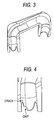
- the circulation part provided in the ball screw of Patent Documents 1 and 2 is formed as shown in Fig. 3 and twisted in a direction so that the part can scoop up the balls. Therefore, a load, which is given to the circulation part when the balls collide with the circulation part, can be reduced.
- only one component in the circulation part, in which two components are combined with each other, is shown in Fig. 3.
- the circulation part Since the shape of the circulation part described above is complicated, the circulation part is manufactured by means of injection molding in many cases. In order to reduce the manufacturing cost, it is preferable that the circulation part is manufactured by means of injection molding.
- the circulation part is made of resin material exhibiting an excellent performance at high temperatures.
- the present invention has been accomplished to solve the above problems of the prior art. It is a task of the present invention to provide a linear motion device of the low noise type which is seldom damaged even when it is driven at high speed.
- the present invention is constructed as follows. That is, the present invention of aspect 1 provides a linear motion device including: a guide member having a rolling element raceway surface and extending in the axial direction; a movable member having a rolling element raceway surface, which is opposed to the rolling element raceway surface of the guide member, supported by the guide member being capable of moving in the axial direction via the rolling of a plurality of rolling elements arranged in a rolling element rolling passage formed between both the rolling element raceway surfaces; and a rolling element circulating passage in which the rolling elements are circulated by sending the rolling elements from an end point of the rolling element rolling passage to a start point, wherein the rolling element circulating passage is made of resin material, the bending elastic modulus of which is not more than 5000 MPa and the Izod impact value (A notch is made in the specimen.) of which is not less than 5 kJ/m 2 .
- the rolling element circulating passage of the linear motion device is made of resin material described above, even when the linear motion device is driven at high speed, the rolling element circulating passage is seldom damaged. If the bending elastic modulus of the resin material exceeds 5000 MPa or the Izod impact value (A notch is made in the specimen.) is lower than 5 kJ/m 2 , when the linear motion device is driven at high speed, the rolling element circulating passage is likely to be damaged. In this connection, the bending elastic modulus and the Izod impact value (A notch is made in the specimen.) described above are values measured at 23°C.
- the present invention described in aspect 2 provides a linear motion device according to aspect 1, wherein the resin material is polyamide resin, the absorption coefficient of which is not less than 1 mass % and not more than 4 mass %.
- the linear motion device even when the linear motion device is driven at high temperatures, the linear motion device is seldom damaged.
- the absorption ratio of polyamide resin is lower than 1 mass %, the bending elastic modulus and the Izod impact value are out of the above referable ranges, and the circulation part tends to be damaged.
- the absorption ratio of polyamide resin exceeds 4 mass %, the dimensions are greatly changed because of water absorption.
- the present invention described in aspect 3 provides a linear motion device according to aspect 1 or 2, wherein end portions of the rolling element circulating passage are arranged in the tangential direction of the rolling element rolling passage at the start point and the end point of the rolling element rolling passage, and the rolling elements are moved between the rolling element rolling passage and the rolling element circulating passage in the tangential direction.
- the rolling elements when the rolling elements are scooped up from the rolling element rolling passage to the rolling element circulating passage, the rolling elements are moved along the tangential direction of the rolling element rolling passage, that is, the rolling elements are scooped up along the tangent. Therefore, it is possible to reduce a load which is given to the rolling element circulating passage when the rolling elements collide with the rolling element circulating passage. Accordingly, even when the linear motion device is driven at high speed, an intensity of the generated noise is low and the rolling element circulating passage is seldom damaged.
- the rolling element circulating passage in which the rolling elements are scooped up along the tangent are: a tube circulation type, a side cap type and an end difference type.
- the present invention can be applied to various linear motion devices.
- the present invention can be applied to a ball screw, a linear guide and a linear guide bearing.
- the guide member of the present invention is defined as follows. In the case where the linear motion device is a ball screw, the guide member is a screw shaft. In the case where the linear motion device is a linear guide, the guide member is a guide rail. In the case where-the linear motion device is a linear guide bearing, the guide member is a shaft.
- the movable member of the present invention is defined as follows. In the case where the linear motion device is a ball bearing, the movable member is a nut. In the case where the linear motion device is a linear guide, the movable member is a slider. In the case where the linear motion device is a linear guide bearing, the movable member is an outer cylinder.
- the rolling element circulating passage is made of resin material having a predetermined mechanical property. Therefore, even when the linear motion device of the present invention is driven at high speed, it is difficult for the rolling element circulating passage to be damaged.
- the side cap 7 is made of resin material, the bending elastic modulus is not more than 5000 MPa and the Izod impact value (A notch is made in the specimen.) of which is not less than 5 kJ/m 2 , even when the ball screw 1 is driven at high speed or even when the ball screw 1 is heated at high temperature, the side cap 7 is seldom damaged.
- the type of the resin material is not particularly limited, examples of the resin material are polyoxymethylene (POM) and polyamide resin.
- An example of the polyamide resin is an aliphatic polyamide resin such as 46 nylon or 66 nylon. It is preferable that the absorption coefficient is not less than 1 mass % and not more than 4 mass %.
- This resin material may contain a reinforcing agent and an addition agent.
- the balls 4 are scooped up in the tangential direction.
- the end portions of the side cap 7 are arranged in the tangential direction of the rolling element rolling passage at the start paint and the end point of the rolling element rolling passage, that is, when the nut 3 is viewed in the axial direction, the end portions of the side cap are arranged in the tangential direction of the spiral rolling element rolling passage 6. Therefore, the balls 4 are moved between the rolling element rolling passage 6 and the side cap 7 in the tangential direction described above. Therefore, a load given to the side cap 7 when the balls 4 collide with the side cap 7 can be reduced. Accordingly, even when the ball screw 1 is driven at high speed, an intensity of the generated noise is low, and the side cap is seldom damaged.
- this embodiment is an example of the present invention. It should be noted that the present invention is not limited to the above specific embodiment.
- the example is shown in which the side cap is used for the rolling element circulating passage to scoop up the rolling elements.
- any of the rolling element circulating passage such as an end cap type or an end deflector type may be adopted.
- the ball screws are prepared as follows. In the above ball screws, the resin materials of -the side caps 7 are variously changed. Then, the thus prepared ball screws 1 are driven at high speeds, and the running distances of the nuts 3, in which the nuts 3 ran until the tongue portions of the side caps 7 are damaged, are measured.
- the specification and the drive conditions of the ball screw are as follows. Diameter of screw shaft: 50 mm Lead: 12 mm Diameter of ball: 7.9375 mm Maximum feed speed: 0.8 m/s (Rotating speed: 4000 rpm) Stroke: 500 mm Temperature of outer diameter of nut: 80°C Types of the resin materials are polyoxymethylene (POM), 46 nylon, 66 nylon, polyphenylene sulfide (PPS), and polyether etherketone (PEEK).
- POM polyoxymethylene
- PPS polyphenylene sulfide
- PEEK polyether etherketone
- the water absorption ratio of nylon is not less than 1 mass % and not more than 4 mass %. In this case, the absolute dry condition is 0 mass %.
Landscapes
- Engineering & Computer Science (AREA)
- General Engineering & Computer Science (AREA)
- Mechanical Engineering (AREA)
- Transmission Devices (AREA)
- Bearings For Parts Moving Linearly (AREA)
Abstract
Description
- The present application claims foreign priority under 35 USC 119 based on Japanese Patent Application No. 2004-346277, filed on November 30, 2004, the contents of which is incorporated herein by reference in its entirety, and concurrently with the filing of this U.S. patent application.
- The present invention relates to a linear motion device such as a ball screw or a linear guide.
- A linear motion device such as a ball screw or a linear guide, which is linearly moved when rolling elements are rolled, includes a part for circulation (a rolling element circulating passage) in which the rolling elements are circulated. It is conventional to use a metallic pipe or a machined metallic part for the part of circulation. However, according to this conventional structure, problems are encountered from the viewpoints of noise and mechanical strength. For example, in the case of a ball screw (a tube circulation type ball screw) in which a metallic pipe is provided for the circulation part, when the balls are scooped up from the rolling element rolling passage and moved into the circulation part, the angle of each ball is changed by the lead angle and the scooping angle. Therefore, when the balls are driven at high speed, there is a possibility that the noise of high intensity is generated. Further, there is a possibility of lack of the mechanical strength of the circulation part. For the above reasons, it is difficult to raise the speed of driving the ball screw.
- In order to raise the ball driving speed and reduce the generation of noise by solving the above problems, it is effective to scoop up the balls from the rolling element rolling passage by the tangential scooping system. That is, when end portions of the circulating part are arranged so that the end portions can substantially agree with the tangential direction of the rolling element rolling passage and the lead angle direction when the nut of the ball screw is viewed in the axial direction, it is possible to reduce a load given to the circulation part which is generated when the balls collide with the circulation parts at the time of scooping up the balls.
- For example,
Patent Documents 1 to 3 respectively propose a ball screw of the tangential scooping type. The circulation part provided in the ball screw ofPatent Documents - Since the shape of the circulation part described above is complicated, the circulation part is manufactured by means of injection molding in many cases. In order to reduce the manufacturing cost, it is preferable that the circulation part is manufactured by means of injection molding.
- JP-A-2004-108455
- JP-A-2005-083519
- Specification of Germany Utility Model No. 2437497
- However, in order to change a ball moving direction, it is inevitable that a repeated load is given to the circulation part. Accordingly, in the case where the ball screw is driven at high speed, a so-called tongue portion, from which the balls are scooped up from the rolling element rolling passage, is damaged in many cases, that is, chips and cracks are caused in the tongue portion. Concerning the circumstances, refer to Fig. 4.
- In the case where the ball screw is driven at high speed, heat is generated from the ball screw. Therefore, it is necessary that the circulation part is made of resin material exhibiting an excellent performance at high temperatures.
- The present invention has been accomplished to solve the above problems of the prior art. It is a task of the present invention to provide a linear motion device of the low noise type which is seldom damaged even when it is driven at high speed.
- In order to solve the above problems, the present invention is constructed as follows. That is, the present invention of
aspect 1 provides a linear motion device including: a guide member having a rolling element raceway surface and extending in the axial direction; a movable member having a rolling element raceway surface, which is opposed to the rolling element raceway surface of the guide member, supported by the guide member being capable of moving in the axial direction via the rolling of a plurality of rolling elements arranged in a rolling element rolling passage formed between both the rolling element raceway surfaces; and a rolling element circulating passage in which the rolling elements are circulated by sending the rolling elements from an end point of the rolling element rolling passage to a start point, wherein the rolling element circulating passage is made of resin material, the bending elastic modulus of which is not more than 5000 MPa and the Izod impact value (A notch is made in the specimen.) of which is not less than 5 kJ/m2. - Since the rolling element circulating passage of the linear motion device is made of resin material described above, even when the linear motion device is driven at high speed, the rolling element circulating passage is seldom damaged. If the bending elastic modulus of the resin material exceeds 5000 MPa or the Izod impact value (A notch is made in the specimen.) is lower than 5 kJ/m2, when the linear motion device is driven at high speed, the rolling element circulating passage is likely to be damaged. In this connection, the bending elastic modulus and the Izod impact value (A notch is made in the specimen.) described above are values measured at 23°C.
- The present invention described in
aspect 2 provides a linear motion device according toaspect 1, wherein the resin material is polyamide resin, the absorption coefficient of which is not less than 1 mass % and not more than 4 mass %. - According to the above constitution, even when the linear motion device is driven at high temperatures, the linear motion device is seldom damaged. In the case where the absorption ratio of polyamide resin is lower than 1 mass %, the bending elastic modulus and the Izod impact value are out of the above referable ranges, and the circulation part tends to be damaged. When the absorption ratio of polyamide resin exceeds 4 mass %, the dimensions are greatly changed because of water absorption.
- The present invention described in
aspect 3 provides a linear motion device according toaspect - According to the linear motion device described above, for example, when the rolling elements are scooped up from the rolling element rolling passage to the rolling element circulating passage, the rolling elements are moved along the tangential direction of the rolling element rolling passage, that is, the rolling elements are scooped up along the tangent. Therefore, it is possible to reduce a load which is given to the rolling element circulating passage when the rolling elements collide with the rolling element circulating passage. Accordingly, even when the linear motion device is driven at high speed, an intensity of the generated noise is low and the rolling element circulating passage is seldom damaged. Examples of the rolling element circulating passage in which the rolling elements are scooped up along the tangent are: a tube circulation type, a side cap type and an end difference type.
- In this connection, the present invention can be applied to various linear motion devices. For example, the present invention can be applied to a ball screw, a linear guide and a linear guide bearing.
- The guide member of the present invention is defined as follows. In the case where the linear motion device is a ball screw, the guide member is a screw shaft. In the case where the linear motion device is a linear guide, the guide member is a guide rail. In the case where-the linear motion device is a linear guide bearing, the guide member is a shaft. The movable member of the present invention is defined as follows. In the case where the linear motion device is a ball bearing, the movable member is a nut. In the case where the linear motion device is a linear guide, the movable member is a slider. In the case where the linear motion device is a linear guide bearing, the movable member is an outer cylinder.
- In the linear motion device of the present invention, the rolling element circulating passage is made of resin material having a predetermined mechanical property. Therefore, even when the linear motion device of the present invention is driven at high speed, it is difficult for the rolling element circulating passage to be damaged.
-
- Fig. 1 is a plan view showing a ball screw which is an embodiment of the linear motion device of the present invention.
- Fig. 2 is a view of the ball screw shown in Fig. 1, wherein the view is taken in the axial direction.
- Fig. 3 is a perspective view for explaining a shape of the side cap.
- Fig. 4 is a partial enlarged view for explaining damage caused in a tongue of the side cap.
- Referring to the accompanying drawings, an embodiment of the linear motion device of the present invention will be explained in detail. Fig. 1 is a plan view showing a ball screw which is an embodiment of the linear motion device of the present invention. Fig. 2 is a view of the ball screw shown in Fig. 1, wherein the view is taken in the axial direction.
- The
ball screw 1 shown in Figs. 1 and 2 includes: a screw shaft (guide member) 2, on the outer circumferential surface of which a spiral screw groove (rolling element raceway surface) 2a is formed, extending in the axial direction; a nut (movable member), on the inner circumferential surface of which a screw groove (rolling element raceway surface) 3a opposed to thescrew shaft 2 is formed; and a plurality of balls (rolling elements) 4 arranged in a rollingelement rolling passage 6, which is formed between both thescrew grooves balls 4 can be freely rolled. - The side cap (rolling element circulating passage) 7, in which the rolling
balls 4 are scooped up at one end (end point) of the rolling element circulating passage and sent to the other end (start point), is fixed to thenut 3 with thecap presser 7a. - In this
ball screw 1, when thescrew shaft 2 and thenut 3 are relatively rotated via the rolling of the plurality ofballs 4, thescrew shaft 2 and thenut 3 are relatively moved in the axial direction. - Since the
side cap 7 is made of resin material, the bending elastic modulus is not more than 5000 MPa and the Izod impact value (A notch is made in the specimen.) of which is not less than 5 kJ/m2, even when theball screw 1 is driven at high speed or even when theball screw 1 is heated at high temperature, theside cap 7 is seldom damaged. Although the type of the resin material is not particularly limited, examples of the resin material are polyoxymethylene (POM) and polyamide resin. An example of the polyamide resin is an aliphatic polyamide resin such as 46 nylon or 66 nylon. It is preferable that the absorption coefficient is not less than 1 mass % and not more than 4 mass %. This resin material may contain a reinforcing agent and an addition agent. - In this
ball screw 1, theballs 4 are scooped up in the tangential direction. The end portions of theside cap 7 are arranged in the tangential direction of the rolling element rolling passage at the start paint and the end point of the rolling element rolling passage, that is, when thenut 3 is viewed in the axial direction, the end portions of the side cap are arranged in the tangential direction of the spiral rollingelement rolling passage 6. Therefore, theballs 4 are moved between the rollingelement rolling passage 6 and theside cap 7 in the tangential direction described above. Therefore, a load given to theside cap 7 when theballs 4 collide with theside cap 7 can be reduced. Accordingly, even when theball screw 1 is driven at high speed, an intensity of the generated noise is low, and the side cap is seldom damaged. - In this connection, this embodiment is an example of the present invention. It should be noted that the present invention is not limited to the above specific embodiment. For example, in this embodiment, the example is shown in which the side cap is used for the rolling element circulating passage to scoop up the rolling elements. However, any of the rolling element circulating passage such as an end cap type or an end deflector type may be adopted.
- Referring to an embodiment, the present invention will be more specifically explained below. The ball screws are prepared as follows. In the above ball screws, the resin materials of -the side caps 7 are variously changed. Then, the thus prepared ball screws 1 are driven at high speeds, and the running distances of the
nuts 3, in which thenuts 3 ran until the tongue portions of the side caps 7 are damaged, are measured. - The specification and the drive conditions of the ball screw are as follows.
Diameter of screw shaft: 50 mm
Lead: 12 mm
Diameter of ball: 7.9375 mm
Maximum feed speed: 0.8 m/s (Rotating speed: 4000 rpm)
Stroke: 500 mm
Temperature of outer diameter of nut: 80°C
Types of the resin materials are polyoxymethylene (POM), 46 nylon, 66 nylon, polyphenylene sulfide (PPS), and polyether etherketone (PEEK). - The bending elastic moduli and the Izod impact values at 23°C of these resin materials and the results of the test are shown on Table 1.
[Table 1] Type of resin material1) POM 46 nylon 66 nylon PPS PEEK Bending elastic modulus2) 2700 3200 2950 3900 38000 Izod impact value 7 9 5.5 2.5 9 Running distance3) 1000 1200 1100 100 400 1) Unit: MPa 2) Unit: kJ/m2 3) Unit: km - As can be understood from the results shown on Table 1, in the case of the resin materials, the bending elastic modulus of which is not more than 5000 MPa and the Izod impact value (A notch is made in the specimen.) of which is not less than 5 kJ/m2, the running distance is not less than 1000 km. Therefore, the ball screw succeeded in the test. In this connection, concerning PPS and PEEK, damage is caused and it became impossible to drive anymore at an early stage of the running distance of not more than 500 km. However, concerning POM and the two types of nylon, damage is small. Therefore, even after the test is completed because of the occurrence of damage, it is possible to drive the ball screw.
- In the case of PEEK which is a resin material, the Izod impact value of which is high, however, the bending elastic modulus of which is excessively high, and in the case of PPS which is a resin material, the bending elastic modulus of which is low, however, the Izod impact value of which is not sufficiently high, a thin portion such as a tongue portion is likely to be damaged, that is, chips and cracks tend to be caused. In this connection, there is no correlation between the tensile strength of the resin material and the damage caused in the side cap.
- In the case of the two types of nylon, when water is absorbed, it becomes possible to obtain an appropriate value of the bending elastic modulus and it is also becomes possible to obtain an appropriate value of the Izod impact value. Therefore, the occurrence of damage of the circulating parts can be suppressed. However, when water is absorbed, the dimensions are changed. Accordingly, it is preferable that the water absorption ratio of nylon is not less than 1 mass % and not more than 4 mass %. In this case, the absolute dry condition is 0 mass %.
Claims (3)
- A linear motion device comprising:a guide member having a rolling element raceway surface and extending in the axial direction;a movable member having a rolling element raceway surface, which is opposed to the rolling element raceway surface of the guide member, supported by the guide member being capable of moving in the axial direction via the rolling of a plurality of rolling elements arranged in a rolling element rolling passage formed between both the rolling element raceway surfaces; anda rolling element circulating passage in which the rolling elements are circulated by sending the rolling elements from an end point of the rolling element rolling passage to a start point, whereinthe rolling element circulating passage is made of resin material, the bending elastic modulus of which is not more than 5000 MPa and the Izod impact value, in which a notch is made, of which is not less than 5 kJ/m2.
- The linear motion device according to claim 1, wherein
the resin material is polyamide resin, the absorption coefficient of which is not less than 1 mass % and not more than 4 mass %. - The linear motion device according to claim 1, wherein
end portions of the rolling element circulating passage are arranged in the tangential direction of the rolling element rolling passage at the start point and the end point of the rolling element rolling passage, and
the rolling elements are moved between the rolling element rolling passage and the rolling element circulating passage in the tangential direction.
Applications Claiming Priority (1)
| Application Number | Priority Date | Filing Date | Title |
|---|---|---|---|
| JP2004346277A JP2006153181A (en) | 2004-11-30 | 2004-11-30 | Linear motion device |
Publications (2)
| Publication Number | Publication Date |
|---|---|
| EP1662176A2 true EP1662176A2 (en) | 2006-05-31 |
| EP1662176A3 EP1662176A3 (en) | 2008-08-20 |
Family
ID=35457872
Family Applications (1)
| Application Number | Title | Priority Date | Filing Date |
|---|---|---|---|
| EP05026006A Withdrawn EP1662176A3 (en) | 2004-11-30 | 2005-11-29 | Linear motion device |
Country Status (4)
| Country | Link |
|---|---|
| US (1) | US20060137485A1 (en) |
| EP (1) | EP1662176A3 (en) |
| JP (1) | JP2006153181A (en) |
| CN (1) | CN1782466A (en) |
Families Citing this family (10)
| Publication number | Priority date | Publication date | Assignee | Title |
|---|---|---|---|---|
| CN101382188B (en) * | 2007-09-03 | 2010-07-28 | 上银科技股份有限公司 | External circulation type ball screw |
| US20100031763A1 (en) * | 2008-08-05 | 2010-02-11 | Chang-Hsin Kuo | Multi-Cycle Ball Screw |
| US20120090419A1 (en) * | 2008-08-05 | 2012-04-19 | Chang-Hsin Kuo | Multi-cycle ball screw |
| US20100116139A1 (en) * | 2008-11-11 | 2010-05-13 | Chang-Cheng Ho | Chain protector for a linear motion processing machine |
| US9279487B1 (en) | 2009-09-30 | 2016-03-08 | David B. Guglietti | Ball screw and parts |
| US9062748B1 (en) | 2009-09-30 | 2015-06-23 | David B. Guglietti | Ball screw nut |
| CN102171490A (en) * | 2009-12-25 | 2011-08-31 | 日本精工株式会社 | Ball screw |
| JP6385006B2 (en) * | 2015-01-23 | 2018-09-05 | 三菱重工コンプレッサ株式会社 | Linear motion mechanism, valve device, and steam turbine |
| JP6777416B2 (en) * | 2016-03-30 | 2020-10-28 | 日本トムソン株式会社 | Ball screw |
| CN106369124A (en) * | 2016-11-09 | 2017-02-01 | 慈兴集团有限公司 | Ball screw with ball returning device and electric parking brake with ball screw |
Citations (3)
| Publication number | Priority date | Publication date | Assignee | Title |
|---|---|---|---|---|
| JP2004108455A (en) | 2002-09-17 | 2004-04-08 | Nsk Ltd | Ball screw device |
| JP2004346277A (en) | 2003-05-26 | 2004-12-09 | Tomoegawa Paper Co Ltd | Adhesive sheet |
| JP2005083519A (en) | 2003-09-10 | 2005-03-31 | Nsk Ltd | Ball screw device |
Family Cites Families (15)
| Publication number | Priority date | Publication date | Assignee | Title |
|---|---|---|---|---|
| GB1455228A (en) * | 1974-03-13 | 1976-11-10 | Anvar | Drive transmitting mechanisms |
| JPS61136805A (en) * | 1984-12-08 | 1986-06-24 | Nippon Seiko Kk | Linear guide apparatus |
| JP2714863B2 (en) * | 1989-08-18 | 1998-02-16 | 日本トムソン株式会社 | Linear motion guide unit made of resin |
| JPH03213714A (en) * | 1990-01-17 | 1991-09-19 | Nippon Thompson Co Ltd | Resin-made direct-acting guide unit |
| US5102235A (en) * | 1991-01-10 | 1992-04-07 | Thomson Industries, Inc. | Linear motion bearing |
| US5193409A (en) * | 1992-03-31 | 1993-03-16 | Thomson Saginaw Ball Screw Company, Inc. | Multiple circuit internal ball nut return assembly with radial drop-in insert for ball screw devices |
| US5555770A (en) * | 1994-10-12 | 1996-09-17 | Thomson Saginaw Ball Screw Company, Inc. | Ball screw and nut system |
| JP3515126B2 (en) * | 1996-06-21 | 2004-04-05 | Thk株式会社 | Ball screw device |
| JPH11311246A (en) * | 1998-04-28 | 1999-11-09 | Nippon Seiko Kk | Linear guide |
| US5937700A (en) * | 1998-05-12 | 1999-08-17 | Thomson Saginaw Ball Screw Company, L.L.C. | Externally installable ball return crossover systems for ball nut and screw assemblies and methods of constructing and installing them |
| US6176149B1 (en) * | 1999-05-28 | 2001-01-23 | Tsubaki Nakashima Co., Ltd. | Ball screw having spacers |
| DE10297160B4 (en) * | 2001-09-04 | 2015-11-19 | Thk Co., Ltd. | Ball screw |
| JP2003074663A (en) * | 2001-09-05 | 2003-03-12 | Nsk Ltd | Ball screw |
| US6955468B2 (en) * | 2001-11-08 | 2005-10-18 | Nsk.Ltd. | Linear-motion device and ball screw |
| EP1353092B1 (en) * | 2002-04-11 | 2009-06-17 | NSK Ltd., | Linear motion device |
-
2004
- 2004-11-30 JP JP2004346277A patent/JP2006153181A/en not_active Withdrawn
-
2005
- 2005-11-29 EP EP05026006A patent/EP1662176A3/en not_active Withdrawn
- 2005-11-30 US US11/289,539 patent/US20060137485A1/en not_active Abandoned
- 2005-11-30 CN CN200510127060.0A patent/CN1782466A/en active Pending
Patent Citations (3)
| Publication number | Priority date | Publication date | Assignee | Title |
|---|---|---|---|---|
| JP2004108455A (en) | 2002-09-17 | 2004-04-08 | Nsk Ltd | Ball screw device |
| JP2004346277A (en) | 2003-05-26 | 2004-12-09 | Tomoegawa Paper Co Ltd | Adhesive sheet |
| JP2005083519A (en) | 2003-09-10 | 2005-03-31 | Nsk Ltd | Ball screw device |
Also Published As
| Publication number | Publication date |
|---|---|
| JP2006153181A (en) | 2006-06-15 |
| CN1782466A (en) | 2006-06-07 |
| EP1662176A3 (en) | 2008-08-20 |
| US20060137485A1 (en) | 2006-06-29 |
Similar Documents
| Publication | Publication Date | Title |
|---|---|---|
| US20060137485A1 (en) | Linear motion device | |
| US6481305B2 (en) | Roller screw and roller screw roller arranging method | |
| EP0698744A1 (en) | Slide member | |
| EP1375966A3 (en) | Ball screw device and method of manufacturing the same | |
| CN108027028A (en) | Actuator | |
| JPWO2006046636A1 (en) | Screw device | |
| US20090308192A1 (en) | Ball screw device having bearing members of different load | |
| JPH07158715A (en) | Ball screw ball groove shape | |
| US6450055B1 (en) | Ball screw apparatus | |
| KR20070011452A (en) | Screw device and its manufacturing method | |
| US20010002783A1 (en) | Single shaft type table feed device | |
| US20020104398A1 (en) | Fail-safe ball screw | |
| JP2002181155A (en) | Ball screw | |
| US20060191367A1 (en) | Rolling screw device | |
| US6993992B2 (en) | Ball screw | |
| US20060196291A1 (en) | Electrically driven linear actuator | |
| CN1756916A (en) | Ball screw device | |
| CN109937316B (en) | Ball screw | |
| CN101184935B (en) | Ball screw and motion guide device | |
| US6968752B2 (en) | Drive shaft moving device | |
| EP1837556B1 (en) | Ball screw device | |
| CN112313430B (en) | Ball Screw | |
| JP3150527U (en) | Rolling element screw device | |
| CN116604360B (en) | A high-speed transmission spiral guide pair | |
| TWI885253B (en) | Multi-start ball screw |
Legal Events
| Date | Code | Title | Description |
|---|---|---|---|
| PUAI | Public reference made under article 153(3) epc to a published international application that has entered the european phase |
Free format text: ORIGINAL CODE: 0009012 |
|
| AK | Designated contracting states |
Kind code of ref document: A2 Designated state(s): AT BE BG CH CY CZ DE DK EE ES FI FR GB GR HU IE IS IT LI LT LU LV MC NL PL PT RO SE SI SK TR |
|
| AX | Request for extension of the european patent |
Extension state: AL BA HR MK YU |
|
| PUAL | Search report despatched |
Free format text: ORIGINAL CODE: 0009013 |
|
| AK | Designated contracting states |
Kind code of ref document: A3 Designated state(s): AT BE BG CH CY CZ DE DK EE ES FI FR GB GR HU IE IS IT LI LT LU LV MC NL PL PT RO SE SI SK TR |
|
| AX | Request for extension of the european patent |
Extension state: AL BA HR MK YU |
|
| 17P | Request for examination filed |
Effective date: 20090220 |
|
| AKX | Designation fees paid |
Designated state(s): DE |
|
| STAA | Information on the status of an ep patent application or granted ep patent |
Free format text: STATUS: THE APPLICATION HAS BEEN WITHDRAWN |
|
| 18W | Application withdrawn |
Effective date: 20090504 |