EP1661814A1 - Container - Google Patents
Container Download PDFInfo
- Publication number
- EP1661814A1 EP1661814A1 EP05077519A EP05077519A EP1661814A1 EP 1661814 A1 EP1661814 A1 EP 1661814A1 EP 05077519 A EP05077519 A EP 05077519A EP 05077519 A EP05077519 A EP 05077519A EP 1661814 A1 EP1661814 A1 EP 1661814A1
- Authority
- EP
- European Patent Office
- Prior art keywords
- panel
- blank
- locking member
- slit
- blank according
- Prior art date
- Legal status (The legal status is an assumption and is not a legal conclusion. Google has not performed a legal analysis and makes no representation as to the accuracy of the status listed.)
- Granted
Links
Images



Classifications
-
- B—PERFORMING OPERATIONS; TRANSPORTING
- B65—CONVEYING; PACKING; STORING; HANDLING THIN OR FILAMENTARY MATERIAL
- B65D—CONTAINERS FOR STORAGE OR TRANSPORT OF ARTICLES OR MATERIALS, e.g. BAGS, BARRELS, BOTTLES, BOXES, CANS, CARTONS, CRATES, DRUMS, JARS, TANKS, HOPPERS, FORWARDING CONTAINERS; ACCESSORIES, CLOSURES, OR FITTINGS THEREFOR; PACKAGING ELEMENTS; PACKAGES
- B65D5/00—Rigid or semi-rigid containers of polygonal cross-section, e.g. boxes, cartons or trays, formed by folding or erecting one or more blanks made of paper
- B65D5/20—Rigid or semi-rigid containers of polygonal cross-section, e.g. boxes, cartons or trays, formed by folding or erecting one or more blanks made of paper by folding-up portions connected to a central panel from all sides to form a container body, e.g. of tray-like form
- B65D5/2014—Rigid or semi-rigid containers of polygonal cross-section, e.g. boxes, cartons or trays, formed by folding or erecting one or more blanks made of paper by folding-up portions connected to a central panel from all sides to form a container body, e.g. of tray-like form the central panel having a non rectangular shape
- B65D5/2019—Rigid or semi-rigid containers of polygonal cross-section, e.g. boxes, cartons or trays, formed by folding or erecting one or more blanks made of paper by folding-up portions connected to a central panel from all sides to form a container body, e.g. of tray-like form the central panel having a non rectangular shape with at least partially curved edges or the like
-
- B—PERFORMING OPERATIONS; TRANSPORTING
- B65—CONVEYING; PACKING; STORING; HANDLING THIN OR FILAMENTARY MATERIAL
- B65D—CONTAINERS FOR STORAGE OR TRANSPORT OF ARTICLES OR MATERIALS, e.g. BAGS, BARRELS, BOTTLES, BOXES, CANS, CARTONS, CRATES, DRUMS, JARS, TANKS, HOPPERS, FORWARDING CONTAINERS; ACCESSORIES, CLOSURES, OR FITTINGS THEREFOR; PACKAGING ELEMENTS; PACKAGES
- B65D5/00—Rigid or semi-rigid containers of polygonal cross-section, e.g. boxes, cartons or trays, formed by folding or erecting one or more blanks made of paper
- B65D5/20—Rigid or semi-rigid containers of polygonal cross-section, e.g. boxes, cartons or trays, formed by folding or erecting one or more blanks made of paper by folding-up portions connected to a central panel from all sides to form a container body, e.g. of tray-like form
- B65D5/30—Rigid or semi-rigid containers of polygonal cross-section, e.g. boxes, cartons or trays, formed by folding or erecting one or more blanks made of paper by folding-up portions connected to a central panel from all sides to form a container body, e.g. of tray-like form with tongue-and-slot or like connections between sides and extensions of other sides
- B65D5/301—Rigid or semi-rigid containers of polygonal cross-section, e.g. boxes, cartons or trays, formed by folding or erecting one or more blanks made of paper by folding-up portions connected to a central panel from all sides to form a container body, e.g. of tray-like form with tongue-and-slot or like connections between sides and extensions of other sides the tongue being a part of a lateral extension of a side wall
- B65D5/302—Rigid or semi-rigid containers of polygonal cross-section, e.g. boxes, cartons or trays, formed by folding or erecting one or more blanks made of paper by folding-up portions connected to a central panel from all sides to form a container body, e.g. of tray-like form with tongue-and-slot or like connections between sides and extensions of other sides the tongue being a part of a lateral extension of a side wall combined with a slot provided in an adjacent side wall
Definitions
- the present invention relates to a container and in particular to a container which may be formed by the automated folding of a blank.
- Cardboard and paperboard containers are typically formed from a flat blank that is folded together in an automated process to give a finished product. It is often necessary to form a corner of a tray or box-like container by folding two wall panels into upright configurations and then locking them together.
- One way to lock wall panels together to form such a corner is disclosed in EP 0 016 879.
- the locking mechanism disclosed in EP 0 016 879 is described below with reference to Figures 1 and 2.
- the present invention seeks to provide an improved container, a blank for such a container and method for forming a container from a blank.
- a blank for assembly into a container comprising a base panel, a first wall panel attached to the base panel via a first fold line, a second wall panel attached to the base panel via a second fold line, and a flap panel attached to the first wall panel, the blank further comprising first locking means comprising slit means on the second wall panel and a first locking member on the flap panel, the blank further comprising second locking means comprising slot means on one of the second wall panel or flap panel, and a second locking member on the other of the second wall panel or flap panel; wherein a portion of the first locking member may engage with the slit means, and a portion of the second locking member may engage with the slot, whereby the first and second wall panels are held together.
- the slit means comprises a slit having a first segment substantially perpendicular to the second fold line, a second segment substantially to the second fold line and a third segment joining the first and second segments, the ends of the third segment defining a first acute angle with respect to the second fold line, the first locking member having a first edge portion substantially perpendicular to the first fold line and a second edge portion provided at a second acute angle to the first edge portion, wherein the first locking member is adapted to be inserted through the slit means such that the second edge portion of the first locking member engages with the third segment of the slit means to hold the first and second wall panels together.
- the third slit segment is substantially straight.
- the third slit segment is arcuately shaped.
- said arcuately shaped third slit segment has a convex side directed towards the base panel.
- the first acute angle no greater than about 40°, and the second acute angle is at least about 45°.
- the second locking member comprises a head and a stem, the head having a greater maximum width than the stem, the head being positioned adjacent the edge of the panel distal from the base panel, and the stem extending from the head towards the base panel.
- the first locking member has a truncated arrow shape.
- the slot means has a width less than the maximum width of the head of the second locking member.
- the slot means is provided on the second wall panel and the second locking member is provided on the flap panel.
- the slot means is provided on the flap panel and the second locking member is provided on the second wall panel.
- the blank has a right-angled corner.
- the blank has an arcuate corner.
- the blank has a corner having an angle of about 120°.
- the blank has a corner having an angle of about 135°.
- the blank has a fold line between the flap panel and first wall panel.
- the blank has four sets of first and second locking mechanisms.
- a container formed from a blank as defined above.
- a method of forming a container from a blank comprising providing a blank as defined above, inter-engaging the first locking member with the slit means, and inter-engaging the second locking member with the slot means to form a corner.
- the method further comprises the addition of an article to the container.
- the method further comprises the step of attaching a lid to the container.
- Figure 1 shows a cardboard blank 2 of substantially planar configuration ready for automated assembly to form a three-dimensional container.
- the blank 2 comprises a piece of paperboard with a predefined cut out edge with a number of slots already formed in various portions of the blank, along with predefined score lines.
- the various cut out edges, slots and score lines allow for automated folding and locking processes leading to a final three-dimensional container.
- Figure 1 shows one corner of a base panel 4 of generally square shape having a first wall panel 6 extending along one edge.
- the wall panel 6 is attached to the base panel 4 by a substantially straight scored fold line 8.
- a second wall panel 10 is provided on an adjacent side of the base panel 4, attached thereto by a second fold line 12.
- a locking flap 14 extends from the end of the first wall panel 6 adjacent the second wall panel 10.
- the locking flap 14 is separated from the first wall panel 6 by a third fold line 16, which is an extension of the second fold line 12.
- the free end of the locking flap 14 is shaped to provide a pointed locking member 18.
- the shaped locking member 18 forms one part of a locking mechanism used to connect the first wall panel 6 and the second wall panel 10 together.
- the second part of the locking mechanism is a slit 20 formed on the second wall panel 10.
- the slit 20 comprises a first straight segment 22 that is substantially parallel to the second fold line 12.
- the slit 20 also comprises a second straight portion 24 that extends substantially perpendicularly to the second fold line 12.
- the first segment 22 and the second segment 24 of the slit 20 are joined together by an arcuate third segment 26 having a convex portion projecting towards the base panel 4.
- EP 0 016 879 describes in detail the way in which the locking mechanism shown in Figures 1 and 2 may be engaged in an automated process. The disclosure of EP 0 016 879 is therefore incorporated herein by reference for further details of the locking mechanism.
- the second wall panel 10 is folded along the second fold line 12 to a position substantially perpendicular to the base panel 4.
- the locking flap is bent over the third fold line 16 and the first wall panel 6 is then folded along the first fold line 8 such that the locking member 18 is inserted through the slit 20.
- the tip of the locking member 18 is pushed under the first segment 22 of the slit 20 in a process known as "stripping", which involves the use of an automated arm or tongue.
- Figure 2 is a partial cross-sectional view of the assembled locking mechanism when viewed from the interior of the container.
- the locking member 18 has been inserted through the slit 20 and is retained in this position in the interior of the container by engagement between the upper surface of the locking member 18 and the edges formed by the first segment 22 and third segment 26 of the slit 20.
- a blank according to the present invention is shown in Figure 3 generally at 30.
- the blank is made of a sheet of paperboard that has been cut into a specific shape and provided with score lines and slits (otherwise known as a die-cut carton blank).
- the blank 30 is designed to be assembled in an automated process to initially give an open tray with a hinged lid that may be filled with articles. After filling, the hinged lid is then folded over the open face of the tray and sealed to give a finished, filled carton.
- the carton blank comprises a base panel 32 that forms the floor of the finished carton.
- the base panel 32 is of substantially square shape with arcuate or rounded corners.
- first front panel 34 Attached to one side of the base panel 32 by a fold line is a first front panel 34.
- On opposite sides of the base panel 32 are provided left and right side panels 36 and 38, separated from the base panel 32 by fold lines.
- a back panel 40 On the opposite side of the base panel 32 from the first front panel 34 is provided a back panel 40, separated by a fold line from the base panel 32.
- On the opposite side of the back panel 40 from the base panel 42 is provided a lid panel 42.
- the lid panel 42 is substantially the same size and shape as the base panel 32.
- On the opposite side of the lid panel 42 from the back panel 40 is provided a second front panel 44.
- On the remaining sides of the lid panel 42 On the remaining sides of the lid panel 42 are provided left and right side panels 46 and 48.
- the side panels 46 and 48 and second front panel 44 are separated from the lid panel 42 by fold lines.
- the first front panel 34 extends beyond the width of the base panel 32 in both directions. On each free end of the front panel 34 there are provided locking means 50,52.
- the back panel 40 extends beyond the width of the base panel 32 and lid panel 42 in both directions, each free end of the back panel 40 being provided with locking means 54,56.
- the side panels 36 and 38 do not extend beyond their point of attachments to the base panel 32.
- Each free corner area of the side panels 36 and 38 is provided with a locking mechanism 58,60,62,64.
- the function of the locking mechanisms of the blank 30 is described below in more detail.
- FIG 4 shows the bottom left-hand corner of the blank 30 of Figure 3 in more detail.
- the front panel 34 extends beyond the width of the base panel 32.
- the free end of the front panel 34 is provided with a first locking member 80 that is defined by a slit 84 that runs from the free end of the front panel 34 in a direction approximately towards the centre of the base panel 32.
- the angle between the slit 84 and the free edge of the front panel 34 is about 40°.
- the slit 84 thus defines the locking member 80 having a tip 82, a front edge 86 leading downwards away from the tip 82 to meet a corner 88, leading to a bottom edge 90.
- the angle between the front edge 86 and the bottom edge 90 about the corner 88 is about 120°.
- a slit 70 is provided in the side panel 36, comprising a first straight segment 72 substantially parallel to the fold line joining the side panel 36 to the base panel 32.
- a second straight segment 76 is provided running substantially perpendicularly to the fold line between the base panel 32 and the side panel 36.
- a third arcuate segment 74 connects the first segment 72 to the second segment 76.
- the third segment 74 is arcuate and defines a convex portion of the side panel 36 which projects towards the base panel 32.
- the first locking member 80 and the slit 70 substantially correspond to the prior art locking mechanism disclosed in EP 0 016 879.
- a second locking mechanism comprising a second locking member 100 provided on the front panel 34 and a slot 110 provided on the side panel 36.
- the locking member 100 is defined by two slits extending inwardly from the edge of the front panel 34 distal from the base panel 32.
- the slits define a truncated arrow or mushroom shape having a head 102 near the distal edge of the side panel 34 and a stem 104 extending away from the distal edge.
- the head 102 has a wider maximum width than the stem 104.
- the side panel 36 has a notch or slot 110 provided on the edge distal from the base panel 32.
- the width of the slot 110 is substantially equal to the width of the stem 104 of the locking member 100, but is narrower than the maximum width of the head 102 of the locking member 100.
- the side panel 36 is folded up to a position substantially perpendicular to the base panel 32.
- the front panel 34 is then folded upwards and the free end of the front panel 34 is moved towards the slit 70. As will be shown below, the free end of the front panel 34 is folded in an arcuate manner to follow the rounded corner of the base panel 32.
- Figure 5 shows a partial cross-sectional view from the interior of the partially assembled carton formed from the blank 30.
- the corner 88 of the locking member 80 has been inserted through the slot 70 to be positioned within the interior of the carton.
- the tip 82 of the locking member 80 is positioned through the first segment 72 of the slot 70 and is positioned on the exterior of the carton.
- the second locking member 100 is positioned on the exterior of slot 110, in registration therewith.
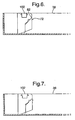
- Figure 6 shows the next stage in the assembly of the carton, with the tip 82 of the locking member 80 having been pushed under and through the first segment 72 of the slit 70.
- inter-engagement of the various surfaces of the locking member 80 and the slit 70 ensures that the front panel 34 and the side panel 36 are held together to form the corner of the carton.
- the second locking member 100 is still positioned in registration with but outside the slot 110 in the side panel 36.
- Figure 7 shows the final position with the head 102 of the locking member 100 having been pushed through the slot 110 to rest on the interior of the carton.
- the head 102 of the second locking member 100 abuts against the inner surface of the side panel 36 adjacent the slot 110, holding the side panels 34 and 36 together.
- the above-described process is performed on all of the locking mechanisms provided at each corner to give a completed but unsealed carton 120 as shown in Figure 8.
- the carton 120 has a tray portion 124 formed by the engagement of the base panel 32, front panel 34, back panel 40 and side panels 36 and 38.
- the carton also has a lid portion 122 formed by the lid panel 42, front panel 44 and side panels 46 and 48.
- the next step is the insertion of articles or products into the tray portion 124 followed by folding of the lid portion 122 over the tray portion 124 and sealing to give a sealed, filled, carton.
- the free ends of the front panel 34 and back panel 40 are folded around to follow the arcuate corners of the base panel 32.
- the rounded corners avoid a major problem with traditional cuboid cartons.
- the right-angled corners of traditional cartons have a disadvantage in that they often crumple when subjected to force during manufacture, transport, display and use by the end consumer.
- the crumpled corners can lead to contamination and/or spillage of the contents of the carton.
- the rounded corners ensures that stacks of the carton naturally form air circulation channels where their corners meet which improves the efficiency of refrigeration.
- the synergistic effect of the two locking mechanisms means that three dimensional cartons can be easily assembled in an automated process to give cartons with corners that are more robust than prior art cartons. This is particularly the case in instances where there is an outward force subjected to the corners.
- the carton has rounded corners which inherently exert a force on the locking mechanism which would cause prior art locking mechanisms to deform or become undone, causing the carton to splay, twist or fully open.
- the provision of the second locking mechanism such as that exemplified by the second locking member 100 and the slot 110 provides a mechanism by which the corner of the carton 120 may be locked in place against these forces.
- the head 102 may be pushed through the slot 110 in a simple automated process.
- the combination of the two locking mechanisms ensures that the cartons may be assembled in automated fashion to give a final product that has a robust corner locking mechanism.
- the present invention is also applicable to a wide range of other applications.
- the invention is applicable to right-angled corners, and to other shapes of containers, such as hexagonal or octagonal cartons (having corners of 120° and 135°, respectively). It can also be used in conjunction with containers having rounded corners that are not substantially square, for example, in triangular-shaped cartons with rounded corners.
- the various members of the locking mechanisms that may be distributed in other arrangements on the blank.
- the second locking members 100 are provided on the front panel 34 and rear panel 40, whilst the corresponding slots 110 are formed on the side panels 36 and 38.
- the positions of the slots 110 and locking members 100 may be reversed, to give an alternative blank having locking members 100 provided on the side panels 36 and 38, and slots 110 provided on the front panel 34 and rear panel 40.
- the invention is applicable to locking members having shapes and configurations different from the specific shape and configuration of the members 100 and slots 110.
- the blanks used to make the cartons of the invention may also be provided with other slots, slits, fold lines and perforations.
- perforations may be provided in the blank to give a predetermined line or area of weakness that the consumer may easily open to access the contents of the carton.
- Figure 8 shows a carton 120 having a lid 122 which is to be glued into position on the tray portion 124, the invention is also applicable to cartons which do not have a lid as such, or to cartons having lids which are attached in ways not involving glue, for example by interlocking members.
Landscapes
- Engineering & Computer Science (AREA)
- Mechanical Engineering (AREA)
- Cartons (AREA)
- Glass Compositions (AREA)
- Packages (AREA)
Abstract
Description
- The present invention relates to a container and in particular to a container which may be formed by the automated folding of a blank.
- Cardboard and paperboard containers are typically formed from a flat blank that is folded together in an automated process to give a finished product. It is often necessary to form a corner of a tray or box-like container by folding two wall panels into upright configurations and then locking them together. One way to lock wall panels together to form such a corner is disclosed in EP 0 016 879. The locking mechanism disclosed in EP 0 016 879 is described below with reference to Figures 1 and 2. Although this prior art system allows for automated formation of containers with interlocked corners, prior art systems such as this still suffer from a number of disadvantages.
- Although the system in EP 0 016 879 allows wall panels to be connected together to form a corner, the locking mechanism can work loose and become undone whilst the container is being transported or handled, particularly by the end consumer. When the locking mechanism is becoming loose, the wall panels can splay outwards to give an unattractive appearance to the container. Furthermore, articles or products stored within the container can escape if the wall panels become unlocked from each other.
- There exists a need therefore for an improved container that may be formed from a blank in an automated process. In particular, there exists a need for an improved locking mechanism for a corner of such a container.
- The present invention seeks to provide an improved container, a blank for such a container and method for forming a container from a blank.
- According to one aspect of the present invention there is provided a blank for assembly into a container, the blank comprising a base panel, a first wall panel attached to the base panel via a first fold line, a second wall panel attached to the base panel via a second fold line, and a flap panel attached to the first wall panel, the blank further comprising first locking means comprising slit means on the second wall panel and a first locking member on the flap panel, the blank further comprising second locking means comprising slot means on one of the second wall panel or flap panel, and a second locking member on the other of the second wall panel or flap panel; wherein a portion of the first locking member may engage with the slit means, and a portion of the second locking member may engage with the slot, whereby the first and second wall panels are held together.
- Preferably, the slit means comprises a slit having a first segment substantially perpendicular to the second fold line, a second segment substantially to the second fold line and a third segment joining the first and second segments, the ends of the third segment defining a first acute angle with respect to the second fold line, the first locking member having a first edge portion substantially perpendicular to the first fold line and a second edge portion provided at a second acute angle to the first edge portion, wherein the first locking member is adapted to be inserted through the slit means such that the second edge portion of the first locking member engages with the third segment of the slit means to hold the first and second wall panels together.
- Conveniently, the third slit segment is substantially straight.
- Advantageously, the third slit segment is arcuately shaped.
- Preferably, said arcuately shaped third slit segment has a convex side directed towards the base panel.
- Conveniently, the first acute angle no greater than about 40°, and the second acute angle is at least about 45°.
- Advantageously, the second locking member comprises a head and a stem, the head having a greater maximum width than the stem, the head being positioned adjacent the edge of the panel distal from the base panel, and the stem extending from the head towards the base panel.
- Preferably, the first locking member has a truncated arrow shape.
- Conveniently, the slot means has a width less than the maximum width of the head of the second locking member.
- Advantageously, the slot means is provided on the second wall panel and the second locking member is provided on the flap panel.
- Preferably, the slot means is provided on the flap panel and the second locking member is provided on the second wall panel.
- Conveniently, the blank has a right-angled corner.
- Advantageously, the blank has an arcuate corner.
- Preferably, the blank has a corner having an angle of about 120°.
- Conveniently, the blank has a corner having an angle of about 135°.
- Advantageously, the blank has a fold line between the flap panel and first wall panel.
- Preferably, the blank has four sets of first and second locking mechanisms.
- According to another aspect of the present invention, there is provided a container formed from a blank as defined above.
- According to a further aspect of the present invention, there is provided a method of forming a container from a blank comprising providing a blank as defined above, inter-engaging the first locking member with the slit means, and inter-engaging the second locking member with the slot means to form a corner.
- Preferably, the method further comprises the addition of an article to the container.
- Conveniently, the method further comprises the step of attaching a lid to the container.
- The present invention will now be described, by way of example, with reference to the accompanying Figures in which
- Figure 1 is a partial plan view of a blank for a container according to the prior art,
- Figure 2 is a partial cross-sectional view of a container formed from the blank shown in Figure 1,
- Figure 3 is a plan view of a blank for a container in accordance with the present invention,
- Figure 4 is a partial plan view of the blank shown in Figure 3 showing the locking mechanisms,
- Figure 5 is a partial cross-sectional view of a container formed from the blank shown in Figure 4 in an initial stage of locking,
- Figure 6 is a view according to Figure 5 in an intermediate stage of locking
- Figure 7 is a view according to Figure 5 in a final stage of locking, and
- Figure 8 is a perspective view of a container formed from the blank shown in Figure 3.
- Turning to Figure 1, the prior art locking mechanism disclosed in EP 0 016 879 is shown. Figure 1 shows a cardboard blank 2 of substantially planar configuration ready for automated assembly to form a three-dimensional container. The blank 2 comprises a piece of paperboard with a predefined cut out edge with a number of slots already formed in various portions of the blank, along with predefined score lines. As will be described below, the various cut out edges, slots and score lines allow for automated folding and locking processes leading to a final three-dimensional container.
- Figure 1 shows one corner of a
base panel 4 of generally square shape having afirst wall panel 6 extending along one edge. Thewall panel 6 is attached to thebase panel 4 by a substantially straight scoredfold line 8. Asecond wall panel 10 is provided on an adjacent side of thebase panel 4, attached thereto by asecond fold line 12. Alocking flap 14 extends from the end of thefirst wall panel 6 adjacent thesecond wall panel 10. Thelocking flap 14 is separated from thefirst wall panel 6 by athird fold line 16, which is an extension of thesecond fold line 12. The free end of thelocking flap 14 is shaped to provide apointed locking member 18. Theshaped locking member 18 forms one part of a locking mechanism used to connect thefirst wall panel 6 and thesecond wall panel 10 together. The second part of the locking mechanism is aslit 20 formed on thesecond wall panel 10. Theslit 20 comprises a firststraight segment 22 that is substantially parallel to thesecond fold line 12. Theslit 20 also comprises a secondstraight portion 24 that extends substantially perpendicularly to thesecond fold line 12. Thefirst segment 22 and thesecond segment 24 of theslit 20 are joined together by an arcuatethird segment 26 having a convex portion projecting towards thebase panel 4. - EP 0 016 879 describes in detail the way in which the locking mechanism shown in Figures 1 and 2 may be engaged in an automated process. The disclosure of EP 0 016 879 is therefore incorporated herein by reference for further details of the locking mechanism.
- In general, the
second wall panel 10 is folded along thesecond fold line 12 to a position substantially perpendicular to thebase panel 4. The locking flap is bent over thethird fold line 16 and thefirst wall panel 6 is then folded along thefirst fold line 8 such that thelocking member 18 is inserted through theslit 20. The tip of thelocking member 18 is pushed under thefirst segment 22 of theslit 20 in a process known as "stripping", which involves the use of an automated arm or tongue. - The final position of the locking mechanism is shown in Figure 2, which is a partial cross-sectional view of the assembled locking mechanism when viewed from the interior of the container. The
locking member 18 has been inserted through theslit 20 and is retained in this position in the interior of the container by engagement between the upper surface of thelocking member 18 and the edges formed by thefirst segment 22 andthird segment 26 of theslit 20. - This prior art locking mechanism allows for rapid automated assembly to give a container with a relatively robust corner. However" under certain circumstances, during folding, the roundness of the corner can be altered leading to unwanted consequences.
- A blank according to the present invention is shown in Figure 3 generally at 30. The blank is made of a sheet of paperboard that has been cut into a specific shape and provided with score lines and slits (otherwise known as a die-cut carton blank). The blank 30 is designed to be assembled in an automated process to initially give an open tray with a hinged lid that may be filled with articles. After filling, the hinged lid is then folded over the open face of the tray and sealed to give a finished, filled carton.
- The carton blank comprises a
base panel 32 that forms the floor of the finished carton. Thebase panel 32 is of substantially square shape with arcuate or rounded corners. - Attached to one side of the
base panel 32 by a fold line is a firstfront panel 34. On opposite sides of thebase panel 32 are provided left andright side panels 36 and 38, separated from thebase panel 32 by fold lines. On the opposite side of thebase panel 32 from the firstfront panel 34 is provided aback panel 40, separated by a fold line from thebase panel 32. On the opposite side of theback panel 40 from thebase panel 42 is provided alid panel 42. Thelid panel 42 is substantially the same size and shape as thebase panel 32. On the opposite side of thelid panel 42 from theback panel 40 is provided a secondfront panel 44. On the remaining sides of thelid panel 42 are provided left andright side panels side panels front panel 44 are separated from thelid panel 42 by fold lines. - The first
front panel 34 extends beyond the width of thebase panel 32 in both directions. On each free end of thefront panel 34 there are provided locking means 50,52. In a similar fashion, theback panel 40 extends beyond the width of thebase panel 32 andlid panel 42 in both directions, each free end of theback panel 40 being provided with locking means 54,56. - The
side panels 36 and 38 do not extend beyond their point of attachments to thebase panel 32. Each free corner area of theside panels 36 and 38 is provided with alocking mechanism - Figure 4 shows the bottom left-hand corner of the blank 30 of Figure 3 in more detail. As can be seen, the
front panel 34 extends beyond the width of thebase panel 32. The free end of thefront panel 34 is provided with afirst locking member 80 that is defined by aslit 84 that runs from the free end of thefront panel 34 in a direction approximately towards the centre of thebase panel 32. The angle between theslit 84 and the free edge of thefront panel 34 is about 40°. Theslit 84 thus defines the lockingmember 80 having atip 82, afront edge 86 leading downwards away from thetip 82 to meet acorner 88, leading to abottom edge 90. The angle between thefront edge 86 and thebottom edge 90 about thecorner 88 is about 120°. - A
slit 70 is provided in theside panel 36, comprising a firststraight segment 72 substantially parallel to the fold line joining theside panel 36 to thebase panel 32. A secondstraight segment 76 is provided running substantially perpendicularly to the fold line between thebase panel 32 and theside panel 36. A thirdarcuate segment 74 connects thefirst segment 72 to thesecond segment 76. Thethird segment 74 is arcuate and defines a convex portion of theside panel 36 which projects towards thebase panel 32. As will be described below, the first lockingmember 80 and theslit 70 substantially correspond to the prior art locking mechanism disclosed in EP 0 016 879. - There is also provided a second locking mechanism comprising a
second locking member 100 provided on thefront panel 34 and aslot 110 provided on theside panel 36. The lockingmember 100 is defined by two slits extending inwardly from the edge of thefront panel 34 distal from thebase panel 32. The slits define a truncated arrow or mushroom shape having ahead 102 near the distal edge of theside panel 34 and astem 104 extending away from the distal edge. Thehead 102 has a wider maximum width than thestem 104. - The
side panel 36 has a notch or slot 110 provided on the edge distal from thebase panel 32. The width of theslot 110 is substantially equal to the width of thestem 104 of the lockingmember 100, but is narrower than the maximum width of thehead 102 of the lockingmember 100. - In the automated assembly process, the
side panel 36 is folded up to a position substantially perpendicular to thebase panel 32. Thefront panel 34 is then folded upwards and the free end of thefront panel 34 is moved towards theslit 70. As will be shown below, the free end of thefront panel 34 is folded in an arcuate manner to follow the rounded corner of thebase panel 32. - Figure 5 shows a partial cross-sectional view from the interior of the partially assembled carton formed from the blank 30. The
corner 88 of the lockingmember 80 has been inserted through theslot 70 to be positioned within the interior of the carton. However, thetip 82 of the lockingmember 80 is positioned through thefirst segment 72 of theslot 70 and is positioned on the exterior of the carton. Thesecond locking member 100 is positioned on the exterior ofslot 110, in registration therewith. - Figure 6 shows the next stage in the assembly of the carton, with the
tip 82 of the lockingmember 80 having been pushed under and through thefirst segment 72 of theslit 70. As described in EP 0 016 879, inter-engagement of the various surfaces of the lockingmember 80 and theslit 70 ensures that thefront panel 34 and theside panel 36 are held together to form the corner of the carton. However, in this position, thesecond locking member 100 is still positioned in registration with but outside theslot 110 in theside panel 36. - Figure 7 shows the final position with the
head 102 of the lockingmember 100 having been pushed through theslot 110 to rest on the interior of the carton. Thehead 102 of thesecond locking member 100 abuts against the inner surface of theside panel 36 adjacent theslot 110, holding theside panels - The above-described process is performed on all of the locking mechanisms provided at each corner to give a completed but unsealed
carton 120 as shown in Figure 8. Thecarton 120 has atray portion 124 formed by the engagement of thebase panel 32,front panel 34, backpanel 40 andside panels 36 and 38. The carton also has alid portion 122 formed by thelid panel 42,front panel 44 andside panels tray portion 124 followed by folding of thelid portion 122 over thetray portion 124 and sealing to give a sealed, filled, carton. - As mentioned above, the free ends of the
front panel 34 and backpanel 40 are folded around to follow the arcuate corners of thebase panel 32. This gives a completed carton with an aesthetically pleasing appearance. Furthermore, the rounded corners avoid a major problem with traditional cuboid cartons. The right-angled corners of traditional cartons have a disadvantage in that they often crumple when subjected to force during manufacture, transport, display and use by the end consumer. In addition to reducing the aesthetic qualities of the finished carton, the crumpled corners can lead to contamination and/or spillage of the contents of the carton. Also, in situations where the contents of the carton are refrigerated or frozen, the rounded corners ensures that stacks of the carton naturally form air circulation channels where their corners meet which improves the efficiency of refrigeration. - The synergistic effect of the two locking mechanisms means that three dimensional cartons can be easily assembled in an automated process to give cartons with corners that are more robust than prior art cartons. This is particularly the case in instances where there is an outward force subjected to the corners. In the example shown in Figure 8, the carton has rounded corners which inherently exert a force on the locking mechanism which would cause prior art locking mechanisms to deform or become undone, causing the carton to splay, twist or fully open. The provision of the second locking mechanism, such as that exemplified by the
second locking member 100 and theslot 110 provides a mechanism by which the corner of thecarton 120 may be locked in place against these forces. Thehead 102 may be pushed through theslot 110 in a simple automated process. The combination of the two locking mechanisms ensures that the cartons may be assembled in automated fashion to give a final product that has a robust corner locking mechanism. In addition to its use on arcuate corners such as that shown in Figure 8, the present invention is also applicable to a wide range of other applications. For example, the invention is applicable to right-angled corners, and to other shapes of containers, such as hexagonal or octagonal cartons (having corners of 120° and 135°, respectively). It can also be used in conjunction with containers having rounded corners that are not substantially square, for example, in triangular-shaped cartons with rounded corners. - It is evident to a person skilled in the art that the various members of the locking mechanisms that may be distributed in other arrangements on the blank. For example, in the embodiment shown in Figure 3, the
second locking members 100 are provided on thefront panel 34 andrear panel 40, whilst the correspondingslots 110 are formed on theside panels 36 and 38. However, the positions of theslots 110 and lockingmembers 100 may be reversed, to give an alternative blank having lockingmembers 100 provided on theside panels 36 and 38, andslots 110 provided on thefront panel 34 andrear panel 40. Also, the invention is applicable to locking members having shapes and configurations different from the specific shape and configuration of themembers 100 andslots 110. - In addition, the blanks used to make the cartons of the invention may also be provided with other slots, slits, fold lines and perforations. For example, perforations may be provided in the blank to give a predetermined line or area of weakness that the consumer may easily open to access the contents of the carton. Also, although Figure 8 shows a
carton 120 having alid 122 which is to be glued into position on thetray portion 124, the invention is also applicable to cartons which do not have a lid as such, or to cartons having lids which are attached in ways not involving glue, for example by interlocking members.
Claims (24)
- A blank for assembly into a container, the blank comprising a base panel, a first wall panel attached to the base panel via a first fold line, a second wall panel attached to the base panel via a second fold line, and a flap panel attached to the first wall panel, the blank further comprising first locking means comprising slit means on the second wall panel and a first locking member on the flap panel, the blank further comprising second locking means comprising slot means on one of the second wall panel or flap panel, and a second locking member on the other of the second wall panel or flap panel; wherein a portion of the first locking member may engage with the slit means, and a portion of the second locking member may engage with the slot means, whereby the first and second wall panels are held together.
- A blank according to Claim 1, wherein the slit means comprises a slit having a first segment substantially perpendicular to the second fold line, a second segment substantially to the second fold line and a third segment joining the first and second segments, the ends of the third segment defining a first acute angle with respect to the second fold line, the first locking member having a first edge portion substantially perpendicular to the first fold line and a second edge portion provided at a second acute angle to the first edge portion wherein the first locking member is adapted to be inserted through the slit means such that the second edge portion of the first locking member engages with the third segment of the slit means to hold the first and second wall panels together.
- A blank according to Claim 2, wherein the third slit segment is substantially straight.
- A blank according to Claim 2, wherein the third slit segment is arcuately shaped.
- A blank according to Claim 4, wherein said arcuately shaped third slit segment has a convex side directed towards the base panel.
- A blank according to any of Claims 2 to 5, wherein the first acute angle is no greater than about 40°, and the second acute angle is at least about 45°.
- A blank according to any preceding claim, wherein the second locking member comprises a head and a stem, the head having a greater maximum width than the stem, the head being positioned adjacent the edge of the panel distal from the base panel, and the stem extending from the head towards the base panel.
- A blank according to any preceding claim, wherein the first locking member has a truncated arrow shape.
- A blank according to Claim 7 or Claim 8, wherein the slot means has a width less than the maximum width of the head of the second locking member.
- A blank according to any preceding claim, wherein the slot means is provided on the second wall panel and the second locking member is provided on the flap panel.
- A blank according to any of Claims 1 to 9, wherein the slot means is provided on the flap panel and the second locking member is provided on the second wall panel.
- A blank according to any preceding claim, which has a right-angled corner.
- A blank according to any preceding claim, which has an arcuate corner.
- A blank according to any preceding claim, which has a corner having an angle of about 120°.
- A blank according to any preceding claim, which has a corner having an angle of about 135°.
- A blank according to any preceding claim, having a fold line between the flap panel and first wall panel.
- A blank according to any preceding claim, having four sets of first and second locking mechanisms.
- A container formed from a blank as defined in any preceding claim.
- A method of forming a container from a blank comprising providing a blank as defined in any of Claims 1 to 17, inter-engaging the first locking member with the slit means, and inter-engaging the second locking member with the slot means to form a corner.
- A method according to Claim 19, further comprising the addition of an article to the container.
- A method according to Claim 19 or Claim 20, further comprising the step of attaching a lid to the container.
- A blank substantially as hereinbefore described with reference to and as shown in the accompanying drawings.
- A container substantially as hereinbefore described with reference to and as shown in the accompanying drawings.
- A method for forming a container from a blank substantially as hereinbefore described with reference to and as shown in the accompanying drawings.
Priority Applications (1)
| Application Number | Priority Date | Filing Date | Title |
|---|---|---|---|
| EP05077519A EP1661814B1 (en) | 2004-11-26 | 2005-11-03 | Container |
Applications Claiming Priority (2)
| Application Number | Priority Date | Filing Date | Title |
|---|---|---|---|
| EP04257368 | 2004-11-26 | ||
| EP05077519A EP1661814B1 (en) | 2004-11-26 | 2005-11-03 | Container |
Publications (2)
| Publication Number | Publication Date |
|---|---|
| EP1661814A1 true EP1661814A1 (en) | 2006-05-31 |
| EP1661814B1 EP1661814B1 (en) | 2009-10-28 |
Family
ID=34930849
Family Applications (1)
| Application Number | Title | Priority Date | Filing Date |
|---|---|---|---|
| EP05077519A Expired - Lifetime EP1661814B1 (en) | 2004-11-26 | 2005-11-03 | Container |
Country Status (7)
| Country | Link |
|---|---|
| EP (1) | EP1661814B1 (en) |
| AT (1) | ATE446912T1 (en) |
| AU (1) | AU2005237171B2 (en) |
| BR (1) | BRPI0505214A (en) |
| DE (1) | DE602005017344D1 (en) |
| ES (1) | ES2332521T3 (en) |
| MX (1) | MXPA05012602A (en) |
Cited By (1)
| Publication number | Priority date | Publication date | Assignee | Title |
|---|---|---|---|---|
| JP2019011128A (en) * | 2017-03-31 | 2019-01-24 | 株式会社パック・ロード | Assembly box |
Families Citing this family (4)
| Publication number | Priority date | Publication date | Assignee | Title |
|---|---|---|---|---|
| GB201205243D0 (en) | 2012-03-26 | 2012-05-09 | Kraft Foods R & D Inc | Packaging and method of opening |
| GB2511559B (en) | 2013-03-07 | 2018-11-14 | Mondelez Uk R&D Ltd | Improved Packaging and Method of Forming Packaging |
| GB2511560B (en) | 2013-03-07 | 2018-11-14 | Mondelez Uk R&D Ltd | Improved Packaging and Method of Forming Packaging |
| KR101476706B1 (en) * | 2014-03-26 | 2014-12-26 | 박현만 | Non-adhesive method for packaging box |
Citations (7)
| Publication number | Priority date | Publication date | Assignee | Title |
|---|---|---|---|---|
| US3226006A (en) * | 1962-11-27 | 1965-12-28 | Memco Machinery Corp | Carton blanks and resulting cartons with fulcrum locking of side panels |
| US3682369A (en) * | 1970-01-05 | 1972-08-08 | Hoerner Waldorf Corp | Panel lock |
| US4189088A (en) * | 1978-10-05 | 1980-02-19 | Westvaco Corporation | Container with interlocking corners |
| EP0016879A1 (en) | 1979-04-09 | 1980-10-15 | Kliklok Corporation | Corner lock carton |
| GB2056951A (en) * | 1979-08-15 | 1981-03-25 | Board Products Ltd | Stacking trays |
| US4687104A (en) * | 1985-06-07 | 1987-08-18 | Patterson Frozen Foods, Inc. | Microwave carton |
| GB2283231A (en) * | 1993-10-26 | 1995-05-03 | Linpac Containers Int | Containers formed from blanks |
-
2005
- 2005-11-03 DE DE602005017344T patent/DE602005017344D1/en not_active Expired - Lifetime
- 2005-11-03 ES ES05077519T patent/ES2332521T3/en not_active Expired - Lifetime
- 2005-11-03 EP EP05077519A patent/EP1661814B1/en not_active Expired - Lifetime
- 2005-11-03 AT AT05077519T patent/ATE446912T1/en not_active IP Right Cessation
- 2005-11-18 BR BRPI0505214-9A patent/BRPI0505214A/en not_active Application Discontinuation
- 2005-11-22 MX MXPA05012602A patent/MXPA05012602A/en active IP Right Grant
- 2005-11-25 AU AU2005237171A patent/AU2005237171B2/en not_active Expired
Patent Citations (7)
| Publication number | Priority date | Publication date | Assignee | Title |
|---|---|---|---|---|
| US3226006A (en) * | 1962-11-27 | 1965-12-28 | Memco Machinery Corp | Carton blanks and resulting cartons with fulcrum locking of side panels |
| US3682369A (en) * | 1970-01-05 | 1972-08-08 | Hoerner Waldorf Corp | Panel lock |
| US4189088A (en) * | 1978-10-05 | 1980-02-19 | Westvaco Corporation | Container with interlocking corners |
| EP0016879A1 (en) | 1979-04-09 | 1980-10-15 | Kliklok Corporation | Corner lock carton |
| GB2056951A (en) * | 1979-08-15 | 1981-03-25 | Board Products Ltd | Stacking trays |
| US4687104A (en) * | 1985-06-07 | 1987-08-18 | Patterson Frozen Foods, Inc. | Microwave carton |
| GB2283231A (en) * | 1993-10-26 | 1995-05-03 | Linpac Containers Int | Containers formed from blanks |
Cited By (1)
| Publication number | Priority date | Publication date | Assignee | Title |
|---|---|---|---|---|
| JP2019011128A (en) * | 2017-03-31 | 2019-01-24 | 株式会社パック・ロード | Assembly box |
Also Published As
| Publication number | Publication date |
|---|---|
| DE602005017344D1 (en) | 2009-12-10 |
| ES2332521T3 (en) | 2010-02-08 |
| BRPI0505214A (en) | 2006-07-11 |
| ATE446912T1 (en) | 2009-11-15 |
| MXPA05012602A (en) | 2006-07-28 |
| EP1661814B1 (en) | 2009-10-28 |
| AU2005237171B2 (en) | 2009-04-23 |
| AU2005237171A1 (en) | 2006-06-15 |
Similar Documents
| Publication | Publication Date | Title |
|---|---|---|
| US9242758B2 (en) | Polygonal containers having a locking bottom and blanks and methods for forming the same | |
| EP3031740B1 (en) | Container made from a flat foldable packaging | |
| US4542847A (en) | Display carton | |
| US10414538B2 (en) | Carton and blank therefor | |
| US5702054A (en) | Single piece food package | |
| JP2011528307A (en) | Carton with handle | |
| CA2956416A1 (en) | Container with a reinforcement structure and method of forming the same | |
| US6935504B2 (en) | Passive interlock structure | |
| US20050199692A1 (en) | Blank capable of forming a container having rounded corners | |
| US20170166348A1 (en) | Polygonal containers having a locking bottom and blanks and methods for forming the same | |
| WO2011137023A1 (en) | Hammer-lock container | |
| EP1661813B1 (en) | Carton box, blank therefor and method for assembling the box | |
| US10865010B2 (en) | Carton and blank therefor | |
| EP2300325B1 (en) | Container | |
| US20040124111A1 (en) | Unistack container with corner stacking tabs | |
| EP1661814B1 (en) | Container | |
| US6651873B2 (en) | Container with bag cuff grab means | |
| WO2012119198A1 (en) | Shelf-ready packaging | |
| US12122565B1 (en) | Display ready corrugated packaging with multiple wall construction | |
| AU2005237170B2 (en) | Container | |
| JP3088549U (en) | Paper tray case | |
| US20050199691A1 (en) | Blank capable of forming a stackable container | |
| US12312134B1 (en) | Display ready corrugated packaging with double corner construction | |
| US20250289612A1 (en) | Packaging Tray | |
| JP2008056262A (en) | Packaging box |
Legal Events
| Date | Code | Title | Description |
|---|---|---|---|
| PUAI | Public reference made under article 153(3) epc to a published international application that has entered the european phase |
Free format text: ORIGINAL CODE: 0009012 |
|
| AK | Designated contracting states |
Kind code of ref document: A1 Designated state(s): AT BE BG CH CY CZ DE DK EE ES FI FR GB GR HU IE IS IT LI LT LU LV MC NL PL PT RO SE SI SK TR |
|
| AX | Request for extension of the european patent |
Extension state: AL BA HR MK YU |
|
| RAP1 | Party data changed (applicant data changed or rights of an application transferred) |
Owner name: UNILEVER N.V. Owner name: UNILEVER PLC |
|
| 17P | Request for examination filed |
Effective date: 20061103 |
|
| 17Q | First examination report despatched |
Effective date: 20061208 |
|
| AKX | Designation fees paid |
Designated state(s): AT BE BG CH CY CZ DE DK EE ES FI FR GB GR HU IE IS IT LI LT LU LV MC NL PL PT RO SE SI SK TR |
|
| RAP1 | Party data changed (applicant data changed or rights of an application transferred) |
Owner name: UNILEVER PLC Owner name: UNILEVER N.V. |
|
| GRAP | Despatch of communication of intention to grant a patent |
Free format text: ORIGINAL CODE: EPIDOSNIGR1 |
|
| GRAS | Grant fee paid |
Free format text: ORIGINAL CODE: EPIDOSNIGR3 |
|
| GRAA | (expected) grant |
Free format text: ORIGINAL CODE: 0009210 |
|
| AK | Designated contracting states |
Kind code of ref document: B1 Designated state(s): AT BE BG CH CY CZ DE DK EE ES FI FR GB GR HU IE IS IT LI LT LU LV MC NL PL PT RO SE SI SK TR |
|
| REG | Reference to a national code |
Ref country code: GB Ref legal event code: FG4D |
|
| REG | Reference to a national code |
Ref country code: CH Ref legal event code: EP |
|
| REG | Reference to a national code |
Ref country code: IE Ref legal event code: FG4D |
|
| REF | Corresponds to: |
Ref document number: 602005017344 Country of ref document: DE Date of ref document: 20091210 Kind code of ref document: P |
|
| REG | Reference to a national code |
Ref country code: ES Ref legal event code: FG2A Ref document number: 2332521 Country of ref document: ES Kind code of ref document: T3 |
|
| LTIE | Lt: invalidation of european patent or patent extension |
Effective date: 20091028 |
|
| NLV1 | Nl: lapsed or annulled due to failure to fulfill the requirements of art. 29p and 29m of the patents act | ||
| PG25 | Lapsed in a contracting state [announced via postgrant information from national office to epo] |
Ref country code: LT Free format text: LAPSE BECAUSE OF FAILURE TO SUBMIT A TRANSLATION OF THE DESCRIPTION OR TO PAY THE FEE WITHIN THE PRESCRIBED TIME-LIMIT Effective date: 20091028 Ref country code: PT Free format text: LAPSE BECAUSE OF FAILURE TO SUBMIT A TRANSLATION OF THE DESCRIPTION OR TO PAY THE FEE WITHIN THE PRESCRIBED TIME-LIMIT Effective date: 20100301 Ref country code: SE Free format text: LAPSE BECAUSE OF FAILURE TO SUBMIT A TRANSLATION OF THE DESCRIPTION OR TO PAY THE FEE WITHIN THE PRESCRIBED TIME-LIMIT Effective date: 20091028 Ref country code: FI Free format text: LAPSE BECAUSE OF FAILURE TO SUBMIT A TRANSLATION OF THE DESCRIPTION OR TO PAY THE FEE WITHIN THE PRESCRIBED TIME-LIMIT Effective date: 20091028 Ref country code: IS Free format text: LAPSE BECAUSE OF FAILURE TO SUBMIT A TRANSLATION OF THE DESCRIPTION OR TO PAY THE FEE WITHIN THE PRESCRIBED TIME-LIMIT Effective date: 20100228 |
|
| PG25 | Lapsed in a contracting state [announced via postgrant information from national office to epo] |
Ref country code: SI Free format text: LAPSE BECAUSE OF FAILURE TO SUBMIT A TRANSLATION OF THE DESCRIPTION OR TO PAY THE FEE WITHIN THE PRESCRIBED TIME-LIMIT Effective date: 20091028 Ref country code: LV Free format text: LAPSE BECAUSE OF FAILURE TO SUBMIT A TRANSLATION OF THE DESCRIPTION OR TO PAY THE FEE WITHIN THE PRESCRIBED TIME-LIMIT Effective date: 20091028 Ref country code: CY Free format text: LAPSE BECAUSE OF FAILURE TO SUBMIT A TRANSLATION OF THE DESCRIPTION OR TO PAY THE FEE WITHIN THE PRESCRIBED TIME-LIMIT Effective date: 20091028 Ref country code: PL Free format text: LAPSE BECAUSE OF FAILURE TO SUBMIT A TRANSLATION OF THE DESCRIPTION OR TO PAY THE FEE WITHIN THE PRESCRIBED TIME-LIMIT Effective date: 20091028 |
|
| PG25 | Lapsed in a contracting state [announced via postgrant information from national office to epo] |
Ref country code: BE Free format text: LAPSE BECAUSE OF FAILURE TO SUBMIT A TRANSLATION OF THE DESCRIPTION OR TO PAY THE FEE WITHIN THE PRESCRIBED TIME-LIMIT Effective date: 20091028 Ref country code: MC Free format text: LAPSE BECAUSE OF NON-PAYMENT OF DUE FEES Effective date: 20091130 Ref country code: AT Free format text: LAPSE BECAUSE OF FAILURE TO SUBMIT A TRANSLATION OF THE DESCRIPTION OR TO PAY THE FEE WITHIN THE PRESCRIBED TIME-LIMIT Effective date: 20091028 |
|
| REG | Reference to a national code |
Ref country code: CH Ref legal event code: PL |
|
| PG25 | Lapsed in a contracting state [announced via postgrant information from national office to epo] |
Ref country code: RO Free format text: LAPSE BECAUSE OF FAILURE TO SUBMIT A TRANSLATION OF THE DESCRIPTION OR TO PAY THE FEE WITHIN THE PRESCRIBED TIME-LIMIT Effective date: 20091028 Ref country code: EE Free format text: LAPSE BECAUSE OF FAILURE TO SUBMIT A TRANSLATION OF THE DESCRIPTION OR TO PAY THE FEE WITHIN THE PRESCRIBED TIME-LIMIT Effective date: 20091028 Ref country code: DK Free format text: LAPSE BECAUSE OF FAILURE TO SUBMIT A TRANSLATION OF THE DESCRIPTION OR TO PAY THE FEE WITHIN THE PRESCRIBED TIME-LIMIT Effective date: 20091028 Ref country code: BG Free format text: LAPSE BECAUSE OF FAILURE TO SUBMIT A TRANSLATION OF THE DESCRIPTION OR TO PAY THE FEE WITHIN THE PRESCRIBED TIME-LIMIT Effective date: 20100128 |
|
| PG25 | Lapsed in a contracting state [announced via postgrant information from national office to epo] |
Ref country code: SK Free format text: LAPSE BECAUSE OF FAILURE TO SUBMIT A TRANSLATION OF THE DESCRIPTION OR TO PAY THE FEE WITHIN THE PRESCRIBED TIME-LIMIT Effective date: 20091028 Ref country code: CZ Free format text: LAPSE BECAUSE OF FAILURE TO SUBMIT A TRANSLATION OF THE DESCRIPTION OR TO PAY THE FEE WITHIN THE PRESCRIBED TIME-LIMIT Effective date: 20091028 |
|
| PLBE | No opposition filed within time limit |
Free format text: ORIGINAL CODE: 0009261 |
|
| STAA | Information on the status of an ep patent application or granted ep patent |
Free format text: STATUS: NO OPPOSITION FILED WITHIN TIME LIMIT |
|
| 26N | No opposition filed |
Effective date: 20100729 |
|
| PG25 | Lapsed in a contracting state [announced via postgrant information from national office to epo] |
Ref country code: CH Free format text: LAPSE BECAUSE OF NON-PAYMENT OF DUE FEES Effective date: 20091130 Ref country code: LI Free format text: LAPSE BECAUSE OF NON-PAYMENT OF DUE FEES Effective date: 20091130 Ref country code: IE Free format text: LAPSE BECAUSE OF NON-PAYMENT OF DUE FEES Effective date: 20091103 Ref country code: GR Free format text: LAPSE BECAUSE OF FAILURE TO SUBMIT A TRANSLATION OF THE DESCRIPTION OR TO PAY THE FEE WITHIN THE PRESCRIBED TIME-LIMIT Effective date: 20100129 |
|
| PG25 | Lapsed in a contracting state [announced via postgrant information from national office to epo] |
Ref country code: LU Free format text: LAPSE BECAUSE OF NON-PAYMENT OF DUE FEES Effective date: 20091103 |
|
| PG25 | Lapsed in a contracting state [announced via postgrant information from national office to epo] |
Ref country code: HU Free format text: LAPSE BECAUSE OF FAILURE TO SUBMIT A TRANSLATION OF THE DESCRIPTION OR TO PAY THE FEE WITHIN THE PRESCRIBED TIME-LIMIT Effective date: 20100429 |
|
| PG25 | Lapsed in a contracting state [announced via postgrant information from national office to epo] |
Ref country code: NL Free format text: LAPSE BECAUSE OF FAILURE TO SUBMIT A TRANSLATION OF THE DESCRIPTION OR TO PAY THE FEE WITHIN THE PRESCRIBED TIME-LIMIT Effective date: 20091028 |
|
| REG | Reference to a national code |
Ref country code: FR Ref legal event code: PLFP Year of fee payment: 11 |
|
| REG | Reference to a national code |
Ref country code: FR Ref legal event code: PLFP Year of fee payment: 12 |
|
| PGFP | Annual fee paid to national office [announced via postgrant information from national office to epo] |
Ref country code: ES Payment date: 20161114 Year of fee payment: 12 |
|
| REG | Reference to a national code |
Ref country code: FR Ref legal event code: PLFP Year of fee payment: 13 |
|
| REG | Reference to a national code |
Ref country code: ES Ref legal event code: FD2A Effective date: 20181226 |
|
| PG25 | Lapsed in a contracting state [announced via postgrant information from national office to epo] |
Ref country code: ES Free format text: LAPSE BECAUSE OF NON-PAYMENT OF DUE FEES Effective date: 20171104 |
|
| REG | Reference to a national code |
Ref country code: DE Ref legal event code: R082 Ref document number: 602005017344 Country of ref document: DE Representative=s name: MEISSNER BOLTE PATENTANWAELTE RECHTSANWAELTE P, DE Ref country code: DE Ref legal event code: R081 Ref document number: 602005017344 Country of ref document: DE Owner name: UNILEVER IP HOLDINGS B.V., NL Free format text: FORMER OWNER: UNILEVER N.V., ROTTERDAM, NL Ref country code: DE Ref legal event code: R081 Ref document number: 602005017344 Country of ref document: DE Owner name: MAGNUM IP HOLDINGS B.V., NL Free format text: FORMER OWNER: UNILEVER N.V., ROTTERDAM, NL |
|
| REG | Reference to a national code |
Ref country code: GB Ref legal event code: 732E Free format text: REGISTERED BETWEEN 20211125 AND 20211201 |
|
| P01 | Opt-out of the competence of the unified patent court (upc) registered |
Effective date: 20230501 |
|
| PGFP | Annual fee paid to national office [announced via postgrant information from national office to epo] |
Ref country code: DE Payment date: 20241121 Year of fee payment: 20 |
|
| PGFP | Annual fee paid to national office [announced via postgrant information from national office to epo] |
Ref country code: GB Payment date: 20241120 Year of fee payment: 20 |
|
| PGFP | Annual fee paid to national office [announced via postgrant information from national office to epo] |
Ref country code: FR Payment date: 20241128 Year of fee payment: 20 |
|
| PGFP | Annual fee paid to national office [announced via postgrant information from national office to epo] |
Ref country code: IT Payment date: 20241121 Year of fee payment: 20 |
|
| PGFP | Annual fee paid to national office [announced via postgrant information from national office to epo] |
Ref country code: TR Payment date: 20241030 Year of fee payment: 20 |
|
| REG | Reference to a national code |
Ref country code: GB Ref legal event code: 732E Free format text: REGISTERED BETWEEN 20250828 AND 20250903 |
|
| REG | Reference to a national code |
Ref country code: DE Ref legal event code: R081 Ref document number: 602005017344 Country of ref document: DE Owner name: MAGNUM IP HOLDINGS B.V., NL Free format text: FORMER OWNER: UNILEVER IP HOLDINGS B.V., ROTTERDAM, NL |
|
| REG | Reference to a national code |
Ref country code: DE Ref legal event code: R071 Ref document number: 602005017344 Country of ref document: DE |
|
| REG | Reference to a national code |
Ref country code: GB Ref legal event code: PE20 Expiry date: 20251102 |