EP1661746A1 - Hybrid vehicle and method of controlling the vehicle - Google Patents
Hybrid vehicle and method of controlling the vehicle Download PDFInfo
- Publication number
- EP1661746A1 EP1661746A1 EP03817998A EP03817998A EP1661746A1 EP 1661746 A1 EP1661746 A1 EP 1661746A1 EP 03817998 A EP03817998 A EP 03817998A EP 03817998 A EP03817998 A EP 03817998A EP 1661746 A1 EP1661746 A1 EP 1661746A1
- Authority
- EP
- European Patent Office
- Prior art keywords
- motor generator
- engine
- torque
- power generation
- engine torque
- Prior art date
- Legal status (The legal status is an assumption and is not a legal conclusion. Google has not performed a legal analysis and makes no representation as to the accuracy of the status listed.)
- Granted
Links
Images


Classifications
-
- B—PERFORMING OPERATIONS; TRANSPORTING
- B60—VEHICLES IN GENERAL
- B60W—CONJOINT CONTROL OF VEHICLE SUB-UNITS OF DIFFERENT TYPE OR DIFFERENT FUNCTION; CONTROL SYSTEMS SPECIALLY ADAPTED FOR HYBRID VEHICLES; ROAD VEHICLE DRIVE CONTROL SYSTEMS FOR PURPOSES NOT RELATED TO THE CONTROL OF A PARTICULAR SUB-UNIT
- B60W20/00—Control systems specially adapted for hybrid vehicles
- B60W20/10—Controlling the power contribution of each of the prime movers to meet required power demand
-
- B—PERFORMING OPERATIONS; TRANSPORTING
- B60—VEHICLES IN GENERAL
- B60K—ARRANGEMENT OR MOUNTING OF PROPULSION UNITS OR OF TRANSMISSIONS IN VEHICLES; ARRANGEMENT OR MOUNTING OF PLURAL DIVERSE PRIME-MOVERS IN VEHICLES; AUXILIARY DRIVES FOR VEHICLES; INSTRUMENTATION OR DASHBOARDS FOR VEHICLES; ARRANGEMENTS IN CONNECTION WITH COOLING, AIR INTAKE, GAS EXHAUST OR FUEL SUPPLY OF PROPULSION UNITS IN VEHICLES
- B60K6/00—Arrangement or mounting of plural diverse prime-movers for mutual or common propulsion, e.g. hybrid propulsion systems comprising electric motors and internal combustion engines
- B60K6/20—Arrangement or mounting of plural diverse prime-movers for mutual or common propulsion, e.g. hybrid propulsion systems comprising electric motors and internal combustion engines the prime-movers consisting of electric motors and internal combustion engines, e.g. HEVs
- B60K6/42—Arrangement or mounting of plural diverse prime-movers for mutual or common propulsion, e.g. hybrid propulsion systems comprising electric motors and internal combustion engines the prime-movers consisting of electric motors and internal combustion engines, e.g. HEVs characterised by the architecture of the hybrid electric vehicle
- B60K6/48—Parallel type
-
- B—PERFORMING OPERATIONS; TRANSPORTING
- B60—VEHICLES IN GENERAL
- B60W—CONJOINT CONTROL OF VEHICLE SUB-UNITS OF DIFFERENT TYPE OR DIFFERENT FUNCTION; CONTROL SYSTEMS SPECIALLY ADAPTED FOR HYBRID VEHICLES; ROAD VEHICLE DRIVE CONTROL SYSTEMS FOR PURPOSES NOT RELATED TO THE CONTROL OF A PARTICULAR SUB-UNIT
- B60W10/00—Conjoint control of vehicle sub-units of different type or different function
- B60W10/04—Conjoint control of vehicle sub-units of different type or different function including control of propulsion units
- B60W10/06—Conjoint control of vehicle sub-units of different type or different function including control of propulsion units including control of combustion engines
-
- B—PERFORMING OPERATIONS; TRANSPORTING
- B60—VEHICLES IN GENERAL
- B60W—CONJOINT CONTROL OF VEHICLE SUB-UNITS OF DIFFERENT TYPE OR DIFFERENT FUNCTION; CONTROL SYSTEMS SPECIALLY ADAPTED FOR HYBRID VEHICLES; ROAD VEHICLE DRIVE CONTROL SYSTEMS FOR PURPOSES NOT RELATED TO THE CONTROL OF A PARTICULAR SUB-UNIT
- B60W10/00—Conjoint control of vehicle sub-units of different type or different function
- B60W10/04—Conjoint control of vehicle sub-units of different type or different function including control of propulsion units
- B60W10/08—Conjoint control of vehicle sub-units of different type or different function including control of propulsion units including control of electric propulsion units, e.g. motors or generators
-
- B—PERFORMING OPERATIONS; TRANSPORTING
- B60—VEHICLES IN GENERAL
- B60W—CONJOINT CONTROL OF VEHICLE SUB-UNITS OF DIFFERENT TYPE OR DIFFERENT FUNCTION; CONTROL SYSTEMS SPECIALLY ADAPTED FOR HYBRID VEHICLES; ROAD VEHICLE DRIVE CONTROL SYSTEMS FOR PURPOSES NOT RELATED TO THE CONTROL OF A PARTICULAR SUB-UNIT
- B60W10/00—Conjoint control of vehicle sub-units of different type or different function
- B60W10/24—Conjoint control of vehicle sub-units of different type or different function including control of energy storage means
- B60W10/26—Conjoint control of vehicle sub-units of different type or different function including control of energy storage means for electrical energy, e.g. batteries or capacitors
-
- B—PERFORMING OPERATIONS; TRANSPORTING
- B60—VEHICLES IN GENERAL
- B60W—CONJOINT CONTROL OF VEHICLE SUB-UNITS OF DIFFERENT TYPE OR DIFFERENT FUNCTION; CONTROL SYSTEMS SPECIALLY ADAPTED FOR HYBRID VEHICLES; ROAD VEHICLE DRIVE CONTROL SYSTEMS FOR PURPOSES NOT RELATED TO THE CONTROL OF A PARTICULAR SUB-UNIT
- B60W20/00—Control systems specially adapted for hybrid vehicles
-
- B—PERFORMING OPERATIONS; TRANSPORTING
- B60—VEHICLES IN GENERAL
- B60L—PROPULSION OF ELECTRICALLY-PROPELLED VEHICLES; SUPPLYING ELECTRIC POWER FOR AUXILIARY EQUIPMENT OF ELECTRICALLY-PROPELLED VEHICLES; ELECTRODYNAMIC BRAKE SYSTEMS FOR VEHICLES IN GENERAL; MAGNETIC SUSPENSION OR LEVITATION FOR VEHICLES; MONITORING OPERATING VARIABLES OF ELECTRICALLY-PROPELLED VEHICLES; ELECTRIC SAFETY DEVICES FOR ELECTRICALLY-PROPELLED VEHICLES
- B60L2240/00—Control parameters of input or output; Target parameters
- B60L2240/40—Drive Train control parameters
- B60L2240/42—Drive Train control parameters related to electric machines
- B60L2240/423—Torque
-
- B—PERFORMING OPERATIONS; TRANSPORTING
- B60—VEHICLES IN GENERAL
- B60L—PROPULSION OF ELECTRICALLY-PROPELLED VEHICLES; SUPPLYING ELECTRIC POWER FOR AUXILIARY EQUIPMENT OF ELECTRICALLY-PROPELLED VEHICLES; ELECTRODYNAMIC BRAKE SYSTEMS FOR VEHICLES IN GENERAL; MAGNETIC SUSPENSION OR LEVITATION FOR VEHICLES; MONITORING OPERATING VARIABLES OF ELECTRICALLY-PROPELLED VEHICLES; ELECTRIC SAFETY DEVICES FOR ELECTRICALLY-PROPELLED VEHICLES
- B60L2240/00—Control parameters of input or output; Target parameters
- B60L2240/40—Drive Train control parameters
- B60L2240/48—Drive Train control parameters related to transmissions
- B60L2240/486—Operating parameters
-
- B—PERFORMING OPERATIONS; TRANSPORTING
- B60—VEHICLES IN GENERAL
- B60W—CONJOINT CONTROL OF VEHICLE SUB-UNITS OF DIFFERENT TYPE OR DIFFERENT FUNCTION; CONTROL SYSTEMS SPECIALLY ADAPTED FOR HYBRID VEHICLES; ROAD VEHICLE DRIVE CONTROL SYSTEMS FOR PURPOSES NOT RELATED TO THE CONTROL OF A PARTICULAR SUB-UNIT
- B60W50/00—Details of control systems for road vehicle drive control not related to the control of a particular sub-unit, e.g. process diagnostic or vehicle driver interfaces
- B60W2050/0001—Details of the control system
- B60W2050/0019—Control system elements or transfer functions
- B60W2050/0028—Mathematical models, e.g. for simulation
- B60W2050/0031—Mathematical model of the vehicle
-
- B—PERFORMING OPERATIONS; TRANSPORTING
- B60—VEHICLES IN GENERAL
- B60W—CONJOINT CONTROL OF VEHICLE SUB-UNITS OF DIFFERENT TYPE OR DIFFERENT FUNCTION; CONTROL SYSTEMS SPECIALLY ADAPTED FOR HYBRID VEHICLES; ROAD VEHICLE DRIVE CONTROL SYSTEMS FOR PURPOSES NOT RELATED TO THE CONTROL OF A PARTICULAR SUB-UNIT
- B60W2510/00—Input parameters relating to a particular sub-units
- B60W2510/24—Energy storage means
- B60W2510/242—Energy storage means for electrical energy
- B60W2510/244—Charge state
-
- B—PERFORMING OPERATIONS; TRANSPORTING
- B60—VEHICLES IN GENERAL
- B60W—CONJOINT CONTROL OF VEHICLE SUB-UNITS OF DIFFERENT TYPE OR DIFFERENT FUNCTION; CONTROL SYSTEMS SPECIALLY ADAPTED FOR HYBRID VEHICLES; ROAD VEHICLE DRIVE CONTROL SYSTEMS FOR PURPOSES NOT RELATED TO THE CONTROL OF A PARTICULAR SUB-UNIT
- B60W2520/00—Input parameters relating to overall vehicle dynamics
- B60W2520/10—Longitudinal speed
-
- B—PERFORMING OPERATIONS; TRANSPORTING
- B60—VEHICLES IN GENERAL
- B60W—CONJOINT CONTROL OF VEHICLE SUB-UNITS OF DIFFERENT TYPE OR DIFFERENT FUNCTION; CONTROL SYSTEMS SPECIALLY ADAPTED FOR HYBRID VEHICLES; ROAD VEHICLE DRIVE CONTROL SYSTEMS FOR PURPOSES NOT RELATED TO THE CONTROL OF A PARTICULAR SUB-UNIT
- B60W2540/00—Input parameters relating to occupants
- B60W2540/10—Accelerator pedal position
-
- B—PERFORMING OPERATIONS; TRANSPORTING
- B60—VEHICLES IN GENERAL
- B60W—CONJOINT CONTROL OF VEHICLE SUB-UNITS OF DIFFERENT TYPE OR DIFFERENT FUNCTION; CONTROL SYSTEMS SPECIALLY ADAPTED FOR HYBRID VEHICLES; ROAD VEHICLE DRIVE CONTROL SYSTEMS FOR PURPOSES NOT RELATED TO THE CONTROL OF A PARTICULAR SUB-UNIT
- B60W2540/00—Input parameters relating to occupants
- B60W2540/12—Brake pedal position
-
- B—PERFORMING OPERATIONS; TRANSPORTING
- B60—VEHICLES IN GENERAL
- B60W—CONJOINT CONTROL OF VEHICLE SUB-UNITS OF DIFFERENT TYPE OR DIFFERENT FUNCTION; CONTROL SYSTEMS SPECIALLY ADAPTED FOR HYBRID VEHICLES; ROAD VEHICLE DRIVE CONTROL SYSTEMS FOR PURPOSES NOT RELATED TO THE CONTROL OF A PARTICULAR SUB-UNIT
- B60W2540/00—Input parameters relating to occupants
- B60W2540/16—Ratio selector position
-
- B—PERFORMING OPERATIONS; TRANSPORTING
- B60—VEHICLES IN GENERAL
- B60W—CONJOINT CONTROL OF VEHICLE SUB-UNITS OF DIFFERENT TYPE OR DIFFERENT FUNCTION; CONTROL SYSTEMS SPECIALLY ADAPTED FOR HYBRID VEHICLES; ROAD VEHICLE DRIVE CONTROL SYSTEMS FOR PURPOSES NOT RELATED TO THE CONTROL OF A PARTICULAR SUB-UNIT
- B60W2710/00—Output or target parameters relating to a particular sub-units
- B60W2710/06—Combustion engines, Gas turbines
- B60W2710/0644—Engine speed
- B60W2710/065—Idle condition
-
- B—PERFORMING OPERATIONS; TRANSPORTING
- B60—VEHICLES IN GENERAL
- B60W—CONJOINT CONTROL OF VEHICLE SUB-UNITS OF DIFFERENT TYPE OR DIFFERENT FUNCTION; CONTROL SYSTEMS SPECIALLY ADAPTED FOR HYBRID VEHICLES; ROAD VEHICLE DRIVE CONTROL SYSTEMS FOR PURPOSES NOT RELATED TO THE CONTROL OF A PARTICULAR SUB-UNIT
- B60W2710/00—Output or target parameters relating to a particular sub-units
- B60W2710/06—Combustion engines, Gas turbines
- B60W2710/0666—Engine torque
-
- B—PERFORMING OPERATIONS; TRANSPORTING
- B60—VEHICLES IN GENERAL
- B60W—CONJOINT CONTROL OF VEHICLE SUB-UNITS OF DIFFERENT TYPE OR DIFFERENT FUNCTION; CONTROL SYSTEMS SPECIALLY ADAPTED FOR HYBRID VEHICLES; ROAD VEHICLE DRIVE CONTROL SYSTEMS FOR PURPOSES NOT RELATED TO THE CONTROL OF A PARTICULAR SUB-UNIT
- B60W2710/00—Output or target parameters relating to a particular sub-units
- B60W2710/08—Electric propulsion units
- B60W2710/083—Torque
-
- Y—GENERAL TAGGING OF NEW TECHNOLOGICAL DEVELOPMENTS; GENERAL TAGGING OF CROSS-SECTIONAL TECHNOLOGIES SPANNING OVER SEVERAL SECTIONS OF THE IPC; TECHNICAL SUBJECTS COVERED BY FORMER USPC CROSS-REFERENCE ART COLLECTIONS [XRACs] AND DIGESTS
- Y02—TECHNOLOGIES OR APPLICATIONS FOR MITIGATION OR ADAPTATION AGAINST CLIMATE CHANGE
- Y02T—CLIMATE CHANGE MITIGATION TECHNOLOGIES RELATED TO TRANSPORTATION
- Y02T10/00—Road transport of goods or passengers
- Y02T10/10—Internal combustion engine [ICE] based vehicles
- Y02T10/40—Engine management systems
-
- Y—GENERAL TAGGING OF NEW TECHNOLOGICAL DEVELOPMENTS; GENERAL TAGGING OF CROSS-SECTIONAL TECHNOLOGIES SPANNING OVER SEVERAL SECTIONS OF THE IPC; TECHNICAL SUBJECTS COVERED BY FORMER USPC CROSS-REFERENCE ART COLLECTIONS [XRACs] AND DIGESTS
- Y02—TECHNOLOGIES OR APPLICATIONS FOR MITIGATION OR ADAPTATION AGAINST CLIMATE CHANGE
- Y02T—CLIMATE CHANGE MITIGATION TECHNOLOGIES RELATED TO TRANSPORTATION
- Y02T10/00—Road transport of goods or passengers
- Y02T10/60—Other road transportation technologies with climate change mitigation effect
- Y02T10/62—Hybrid vehicles
-
- Y—GENERAL TAGGING OF NEW TECHNOLOGICAL DEVELOPMENTS; GENERAL TAGGING OF CROSS-SECTIONAL TECHNOLOGIES SPANNING OVER SEVERAL SECTIONS OF THE IPC; TECHNICAL SUBJECTS COVERED BY FORMER USPC CROSS-REFERENCE ART COLLECTIONS [XRACs] AND DIGESTS
- Y02—TECHNOLOGIES OR APPLICATIONS FOR MITIGATION OR ADAPTATION AGAINST CLIMATE CHANGE
- Y02T—CLIMATE CHANGE MITIGATION TECHNOLOGIES RELATED TO TRANSPORTATION
- Y02T10/00—Road transport of goods or passengers
- Y02T10/60—Other road transportation technologies with climate change mitigation effect
- Y02T10/64—Electric machine technologies in electromobility
-
- Y—GENERAL TAGGING OF NEW TECHNOLOGICAL DEVELOPMENTS; GENERAL TAGGING OF CROSS-SECTIONAL TECHNOLOGIES SPANNING OVER SEVERAL SECTIONS OF THE IPC; TECHNICAL SUBJECTS COVERED BY FORMER USPC CROSS-REFERENCE ART COLLECTIONS [XRACs] AND DIGESTS
- Y10—TECHNICAL SUBJECTS COVERED BY FORMER USPC
- Y10S—TECHNICAL SUBJECTS COVERED BY FORMER USPC CROSS-REFERENCE ART COLLECTIONS [XRACs] AND DIGESTS
- Y10S903/00—Hybrid electric vehicles, HEVS
- Y10S903/902—Prime movers comprising electrical and internal combustion motors
- Y10S903/903—Prime movers comprising electrical and internal combustion motors having energy storing means, e.g. battery, capacitor
- Y10S903/904—Component specially adapted for hev
- Y10S903/905—Combustion engine
Definitions
- This invention relates to a parallel hybrid vehicle comprising an engine and a motor generator as a drive source of the vehicle.
- JP2002-138876A published by the Japan Patent Office in 2002, discloses a parallel hybrid vehicle comprising an engine and a motor generator as a drive source.
- a map for setting an output apportionment ratio of the motor generator and engine in accordance with the SOC of a storage device is stored in a controller.
- the controller refers to the map to determine the output apportionment ratio in accordance with the SOC of the storage device, and controls the output of the motor generator and the output of the engine on the basis of the determined apportionment ratio and an accelerator depression amount.
- This invention provides a hybrid vehicle comprising an engine, a transmission which changes the speed of the rotation of an input shaft and transmits this rotation to an output shaft, a motor generator, a power transmission mechanism which connects a rotary shaft of the motor generator and the input shaft of the transmission, a storage device which is connected to the motor generator, and a controller.
- the controller sets an engine torque at a point on an engine torque high efficiency line at the current engine rotation speed as a target engine torque, calculates the current engine torque from the current engine rotation speed and current accelerator depression amount, and when the gear position of the transmission is neutral, the vehicle is stationary, and the storage device requires charging, sets the difference between the target engine torque and the current engine torque as a target power generation torque of the motor generator, and controls the motor generator such that the power generation torque of the motor generator matches the target power generation torque.
- a hybrid vehicle comprises an engine 1 and a motor generator 2* serving as a drive source, and a step transmission 2 employing a planetary gear.
- a friction clutch 3 is interposed between the engine 1 and transmission 2.
- the engine 1 is a diesel engine or a CNG engine using high-pressure natural gas as a fuel.
- a rotary shaft 4a of the motor generator 4 is connected to an input shaft 2a of the transmission 2 via a power transmission mechanism 5.
- a speed change controller 6 which controls the gear position of the transmission 2 is provided in the transmission 2.
- the speed change controller 6 is connected to a select lever 7 and a main controller 10. When a driver manipulates the select lever 7, the speed change controller 6 controls the gear position of the transmission 2 to realize the gear position selected by the select lever 7.
- the clutch 3 is engaged and disengaged by a clutch actuator 8.
- the clutch actuator 8 engages or disengages the clutch 3 in accordance with a request from the main controller 10, thereby determining whether or not a driving force is transmitted from the engine 1 to the transmission 2 and power transmission mechanism 5.
- An engine controller 15 controls a fuel injection amount (fuel supply amount) of the engine 1.
- the rotation speed of the engine 1 is detected by an engine rotation speed sensor 16.
- the engine controller 15 controls the fuel injection amount of the engine 1 in accordance with a detection signal from the engine rotation speed sensor 16 and a request from the main controller 10.
- a brake actuator 21 which applies a braking force to the wheels is controlled by a brake controller 20 on the basis of information from the main controller 10 (a regenerative braking force of the motor generator 4) and the depression amount of a brake pedal 22 (a requested braking force) to compensate for the part of the requested braking force that cannot be provided fully by the regenerative braking force.
- the depression amount of the brake pedal 22 is detected by a brake sensor 23.
- the motor generator 4 employs a permanent magnet synchronous motor (IPM synchronous motor) due to its high efficiency, small size, and light weight.
- the motor generator 4 is connected to a storage device 9 via an inverter 11.
- the storage device 9 employs an electric double layer capacitor having a high output density for regenerating braking energy with high efficiency, no waste, and in a short time period.
- the inverter 11 controls the motor generator 4 to an electric operation mode or a power generation mode in accordance with a request from the main controller 10.
- the motor generator 4 In the electric operation mode, the motor generator 4 is driven by converting the charged energy (direct current power) of the storage device 9 into alternating current power.
- the power generation mode on the other hand, the storage device 9 is charged by converting the generated energy of the motor generator 4 (alternating current power) into direct current power.
- the power transmission mechanism 5 is constituted by a drive gear 5a connected to the rotary shaft 4a of the motor generator 4, a driven gear 5b connected to the input shaft 2a of the transmission 2, and an idler gear 5c which meshes with the drive gear 5a and driven gear 5b.
- the rotation of the rotary shaft 4a of the motor generator 4 is reduced in speed by the power transmission mechanism 5 and transmitted to the input shaft 2a of the transmission 2.
- the rotation of the input shaft 2a of the transmission 2 is increased in speed by the power transmission mechanism 5 and transmitted to the rotary shaft 4a of the motor generator 4.
- the main controller 10 controls the clutch actuator 8 and the inverter 11 of the motor generator 4 on the basis of these detection signals, as well as various information (information obtained from the engine controller 15, brake controller 20, speed change controller 6, and inverter 11) including the state of charge (SOC) of the storage device 9.
- the main controller 10 also outputs requests to the engine controller 15 and brake controller 20, and commands (speed change commands) to the speed change controller 6.
- FIG. 2 is an output apportionment map which is stored in the main controller 10 and defines the relationship between the SOC of the storage device 9 and the apportionment ratio between the output of the motor generator 4 and the output of the engine 1.
- the main controller 10 refers to the output apportionment map to determine the output apportionment ratio corresponding to the SOC of the storage device 9, and controls the output of the motor generator 4 and the output of the engine 1 on the basis of the apportionment ratio and the requested driving force (accelerator depression amount).
- the main controller 10 controls the inverter 11 such that the motor generator 4 generates its apportioned output, and outputs a request (a fuel supply amount corresponding to the apportioned output of the engine 1) to the engine controller 15 to have the engine 1 generate its apportioned output.
- the inverter 11 When the output apportionment ratio of the motor generator 4 is one (and the output apportionment ratio of the engine 1 is zero), the inverter 11 is controlled with the clutch 3 in a state of disengagement such that an output corresponding to the accelerator depression amount is obtained only from the motor generator 4.
- the inverter 11 When the output apportionment ratio of the motor generator 4 is less than one (and the output apportionment ratio of the engine 1 is greater than zero), the inverter 11 is controlled with the clutch 3 in a state of engagement such that the apportioned output of the motor generator 4 decreases steadily as the SOC of the storage device 9 decreases, and a request is output to the engine controller 15 to increase the apportioned output of the engine 1.
- the main controller 10 cooperates with the brake controller 20 such that whenever the storage device 9 can be charged, the inverter 11 is controlled with the clutch 3 in a state of disengagement to obtain a regenerative braking force corresponding to the brake depression amount (brake pedal depression amount) from the motor generator 4, thereby charging the storage device 9. Further, when the requested braking force corresponding to the brake depression amount cannot be provided fully by the regenerative braking force of the motor generator 4, a request is output to the brake controller 20 to compensate for this part of the braking force with a braking force generated by the brake actuator 21.
- the inverter 11 is controlled to charge the storage device 9 using the power generation of the motor generator 4.
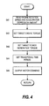
- FIG. 3 is a flowchart illustrating the content of the control executed by the main controller 10 when the vehicle is stationary, which is executed repeatedly in the main controller 10.
- step S1 the detection signal from the gear position sensor 17 is read to determine whether or not the gear position is neutral.
- step S2 the detection signal from the vehicle speed sensor 18 is read to determine whether or not the vehicle has stopped (whether or not the vehicle speed is zero or extremely low).
- step S1 When the determination of the step S1 is affirmative and the determination of the step S2 is affirmative, the process advances to a step S3. On the other hand, when at least one of the determinations in the step S1 and the step S2 is negative, the process is terminated.
- step S3 a determination is made on the basis of the SOC of the storage device 9 as to whether or not the storage device 9 needs to be charged (whether or not the SOC is smaller than a predetermined value SOCth).
- the process advances to the power generation mode of a step S4.
- the process advances to an idling stop mode (control to halt operations of the engine 1) of a step S5.
- FIG. 4 is a flowchart illustrating the content of the processing performed in the step S4, and accordingly the content of the control that is executed in the power generation mode. Maps shown in FIGs. 5-7 are stored in the main controller 10.
- step S41 the detection signal from the engine rotation speed sensor 16 and the detection signal from the accelerator depression amount sensor 13 are read.
- step S42 on the basis of the map shown in FIG. 5, an engine torque at a point on an engine torque high efficiency line at the current engine rotation speed is set as a target engine torque.
- a rack position (fuel injection amount) is determined from the engine rotation speed and accelerator depression amount by referring to the map shown in FIG. 6A. Further, the current engine torque (at the point in time when the engine rotation speed and accelerator depression amount are read in the step S41) is determined from the rack position and engine rotation speed by referring to the map shown in FIG. 6B, and a value obtained by subtracting the current engine torque from the target engine torque is set as a target power generation torque of the motor generator 4.
- a transitional time period corresponding to the target power generation torque is set by referring to the map shown in FIG. 7.
- a step S45 the power generation torque of the motor generator 4 is raised gradually to the target power generation torque over the transitional time period set in the step S44.
- a command is issued to the inverter 11 to maintain the target power generation torque for as long as the conditions of the power generation mode remain established, or in other words until at least one of the determinations in the steps S1-S3 becomes negative. It should be noted that once the target power generation torque has been set, the steps S41-S44 are not executed until at least one of the determinations in the steps S1-S3 becomes negative.
- the power generation torque of the motor generator 4 is controlled to the target power generation torque.
- the storage device 9 is charged by the power generation of the motor generator 4, and hence the state of charge of the storage device 9 increases, enabling an increase in the number of opportunities for starting the vehicle using only the output of the motor generator 4 when the vehicle is restarted.
- the engine 1 is controlled such that the fuel injection amount is increased in accordance with the load (power generation torque) from the motor generator 4, and such that the engine torque is raised while maintaining, the engine rotation speed at a constant level.
- the target engine torque is set such that the operating point of the engine 1 is on the engine torque high efficiency line, and therefore favorable fuel economy and exhaust performance can also be secured.
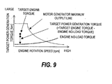
- FIG. 9 is a view illustrating the content of the control executed in the power generation mode.
- the power generation torque of the motor generator 4 is controlled to a target motor torque, which is a value obtained by subtracting an engine no-load torque (the torque required to rotate the engine itself) from the target engine torque.
- the power generation torque of the motor generator 4 is not raised momentarily in a single step to the target power generation torque, as shown by the dotted line in FIG. 8, but instead is raised gradually over the predetermined transitional time period, as shown by the solid line in FIG. 8.
- the load of the engine 1 (the power generation torque) varies gently so that disturbances in the engine rotation speed are avoided, and hence power generation can be performed with stability and without worsening the exhaust performance.
- control system is constituted by a plurality of controllers, but the number of controllers may be increased or decreased, and the control system may be constituted by a single controller.
- This invention may be applied to a parallel hybrid vehicle comprising an engine and a motor generator as a drive source, and is useful for improving starting performance, fuel economy, and exhaust performance.
Landscapes
- Engineering & Computer Science (AREA)
- Chemical & Material Sciences (AREA)
- Combustion & Propulsion (AREA)
- Transportation (AREA)
- Mechanical Engineering (AREA)
- Automation & Control Theory (AREA)
- Hybrid Electric Vehicles (AREA)
- Electric Propulsion And Braking For Vehicles (AREA)
Abstract
Description
- This invention relates to a parallel hybrid vehicle comprising an engine and a motor generator as a drive source of the vehicle.
- JP2002-138876A, published by the Japan Patent Office in 2002, discloses a parallel hybrid vehicle comprising an engine and a motor generator as a drive source. In this conventional example, a map for setting an output apportionment ratio of the motor generator and engine in accordance with the SOC of a storage device is stored in a controller. The controller refers to the map to determine the output apportionment ratio in accordance with the SOC of the storage device, and controls the output of the motor generator and the output of the engine on the basis of the determined apportionment ratio and an accelerator depression amount.
- In this type of hybrid system, when the vehicle is stationary and the gear position of the transmission is neutral, engine idling stop control may be performed. However, if an engine idling stop is performed without taking the state of charge (SOC) of the storage device into account, opportunities for charging the storage device may be lost, and if the state of charge of the storage device decreases, it may be difficult to start the vehicle using only the output of the motor generator. Further, the maximum output of the motor generator is large at low rotation speeds and decreases as the rotation speed increases, and it is therefore desirable that the output of the motor generator be used to the fullest extent when starting the vehicle.
- It is therefore an object of this invention to execute an idling stop appropriately, taking into consideration the state of charge of a storage device, and to enable maximal use of the output of a motor generator during restarting.
- This invention provides a hybrid vehicle comprising an engine, a transmission which changes the speed of the rotation of an input shaft and transmits this rotation to an output shaft, a motor generator, a power transmission mechanism which connects a rotary shaft of the motor generator and the input shaft of the transmission, a storage device which is connected to the motor generator, and a controller. The controller sets an engine torque at a point on an engine torque high efficiency line at the current engine rotation speed as a target engine torque, calculates the current engine torque from the current engine rotation speed and current accelerator depression amount, and when the gear position of the transmission is neutral, the vehicle is stationary, and the storage device requires charging, sets the difference between the target engine torque and the current engine torque as a target power generation torque of the motor generator, and controls the motor generator such that the power generation torque of the motor generator matches the target power generation torque.
- An embodiment of this invention and advantages of this invention will be described in detail below with reference to the attached drawings.
-
- FIG. 1 is a block diagram of a parallel hybrid vehicle according to this invention.
- FIG. 2 is a table defining the relationship between a state of charge of a storage device, and an output apportionment ratio between an engine and a motor generator.
- FIG. 3 is a flowchart showing the content of control executed by a main controller.
- FIG. 4 is a flowchart showing the content of control executed by the main controller in a power generation mode.
- FIG. 5 is a map showing the relationship of a specific fuel consumption to an engine rotation speed and an engine torque.
- FIG. 6A is a map defining the relationship of a rack position (fuel injection amount) to the engine rotation speed and an accelerator depression amount.
- FIG. 6B is a map defining the relationship of the engine torque to the rack position (fuel injection amount) and the engine rotation speed.
- FIG. 7 is a table defining the relationship between a target power generation torque and a transitional time period.
- FIG. 8 is a time chart showing the manner in which the target power generation torque changes.
- FIG. 9 is a view illustrating the content of the control executed in the power generation mode.
- Referring to FIG. 1 of the drawings, a hybrid vehicle comprises an
engine 1 and amotor generator 2* serving as a drive source, and astep transmission 2 employing a planetary gear. Afriction clutch 3 is interposed between theengine 1 andtransmission 2. Theengine 1 is a diesel engine or a CNG engine using high-pressure natural gas as a fuel. Arotary shaft 4a of the motor generator 4 is connected to aninput shaft 2a of thetransmission 2 via apower transmission mechanism 5. - A
speed change controller 6 which controls the gear position of thetransmission 2 is provided in thetransmission 2. Thespeed change controller 6 is connected to aselect lever 7 and amain controller 10. When a driver manipulates theselect lever 7, thespeed change controller 6 controls the gear position of thetransmission 2 to realize the gear position selected by theselect lever 7. - The
clutch 3 is engaged and disengaged by aclutch actuator 8. Theclutch actuator 8 engages or disengages theclutch 3 in accordance with a request from themain controller 10, thereby determining whether or not a driving force is transmitted from theengine 1 to thetransmission 2 andpower transmission mechanism 5. Anengine controller 15 controls a fuel injection amount (fuel supply amount) of theengine 1. The rotation speed of theengine 1 is detected by an enginerotation speed sensor 16. Theengine controller 15 controls the fuel injection amount of theengine 1 in accordance with a detection signal from the enginerotation speed sensor 16 and a request from themain controller 10. - A
brake actuator 21 which applies a braking force to the wheels is controlled by abrake controller 20 on the basis of information from the main controller 10 (a regenerative braking force of the motor generator 4) and the depression amount of a brake pedal 22 (a requested braking force) to compensate for the part of the requested braking force that cannot be provided fully by the regenerative braking force. The depression amount of thebrake pedal 22 is detected by abrake sensor 23. - The motor generator 4 employs a permanent magnet synchronous motor (IPM synchronous motor) due to its high efficiency, small size, and light weight. The motor generator 4 is connected to a
storage device 9 via aninverter 11. Thestorage device 9 employs an electric double layer capacitor having a high output density for regenerating braking energy with high efficiency, no waste, and in a short time period. - The
inverter 11 controls the motor generator 4 to an electric operation mode or a power generation mode in accordance with a request from themain controller 10. In the electric operation mode, the motor generator 4 is driven by converting the charged energy (direct current power) of thestorage device 9 into alternating current power. In the power generation mode, on the other hand, thestorage device 9 is charged by converting the generated energy of the motor generator 4 (alternating current power) into direct current power. - The
power transmission mechanism 5 is constituted by adrive gear 5a connected to therotary shaft 4a of the motor generator 4, a drivengear 5b connected to theinput shaft 2a of thetransmission 2, and anidler gear 5c which meshes with thedrive gear 5a and drivengear 5b. The rotation of therotary shaft 4a of the motor generator 4 is reduced in speed by thepower transmission mechanism 5 and transmitted to theinput shaft 2a of thetransmission 2. Conversely, the rotation of theinput shaft 2a of thetransmission 2 is increased in speed by thepower transmission mechanism 5 and transmitted to therotary shaft 4a of the motor generator 4. - Detection signals from an accelerator
depression amount sensor 13 which detects the depression amount (requested driving force) of anaccelerator pedal 12, aclutch sensor 14 which detects the engagement and disengagement of theclutch 3, agear position sensor 17 which detects the gear position of thetransmission 2, avehicle speed sensor 18 which detects the output side rotation speed of the transmission 2 (i.e. an output rotation speed sensor which detects the output rotation speed of the transmission 2), and arotation speed sensor 19 which detects the rotation speed of thedrive gear 5a, which is connected to therotary shaft 4a of the motor generator 4, as the input side rotation speed of the transmission 2 (i.e. an input rotation speed sensor which detects the input rotation speed of the transmission 2), are input into themain controller 10. - The
main controller 10 controls theclutch actuator 8 and theinverter 11 of the motor generator 4 on the basis of these detection signals, as well as various information (information obtained from theengine controller 15,brake controller 20,speed change controller 6, and inverter 11) including the state of charge (SOC) of thestorage device 9. Themain controller 10 also outputs requests to theengine controller 15 andbrake controller 20, and commands (speed change commands) to thespeed change controller 6. - FIG. 2 is an output apportionment map which is stored in the
main controller 10 and defines the relationship between the SOC of thestorage device 9 and the apportionment ratio between the output of the motor generator 4 and the output of theengine 1. - The
main controller 10 refers to the output apportionment map to determine the output apportionment ratio corresponding to the SOC of thestorage device 9, and controls the output of the motor generator 4 and the output of theengine 1 on the basis of the apportionment ratio and the requested driving force (accelerator depression amount). In other words, themain controller 10 controls theinverter 11 such that the motor generator 4 generates its apportioned output, and outputs a request (a fuel supply amount corresponding to the apportioned output of the engine 1) to theengine controller 15 to have theengine 1 generate its apportioned output. - When the output apportionment ratio of the motor generator 4 is one (and the output apportionment ratio of the
engine 1 is zero), theinverter 11 is controlled with theclutch 3 in a state of disengagement such that an output corresponding to the accelerator depression amount is obtained only from the motor generator 4. - When the output apportionment ratio of the motor generator 4 is less than one (and the output apportionment ratio of the
engine 1 is greater than zero), theinverter 11 is controlled with theclutch 3 in a state of engagement such that the apportioned output of the motor generator 4 decreases steadily as the SOC of thestorage device 9 decreases, and a request is output to theengine controller 15 to increase the apportioned output of theengine 1. - When the output apportionment ratio of the
engine 1 is one (and the output apportionment ratio of the motor generator is zero), a request is output to theengine controller 15 requesting that an output corresponding to the accelerator depression amount be obtained only from theengine 1. - The
main controller 10 cooperates with thebrake controller 20 such that whenever thestorage device 9 can be charged, theinverter 11 is controlled with theclutch 3 in a state of disengagement to obtain a regenerative braking force corresponding to the brake depression amount (brake pedal depression amount) from the motor generator 4, thereby charging thestorage device 9. Further, when the requested braking force corresponding to the brake depression amount cannot be provided fully by the regenerative braking force of the motor generator 4, a request is output to thebrake controller 20 to compensate for this part of the braking force with a braking force generated by thebrake actuator 21. Moreover, when it is determined, on the basis of the SOC of thestorage device 9, that charging is required and there is leeway in the output of theengine 1 with theclutch 3 in a state of engagement, theinverter 11 is controlled to charge thestorage device 9 using the power generation of the motor generator 4. - FIG. 3 is a flowchart illustrating the content of the control executed by the
main controller 10 when the vehicle is stationary, which is executed repeatedly in themain controller 10. - In a step S1, the detection signal from the
gear position sensor 17 is read to determine whether or not the gear position is neutral. In a step S2, the detection signal from thevehicle speed sensor 18 is read to determine whether or not the vehicle has stopped (whether or not the vehicle speed is zero or extremely low). - When the determination of the step S1 is affirmative and the determination of the step S2 is affirmative, the process advances to a step S3. On the other hand, when at least one of the determinations in the step S1 and the step S2 is negative, the process is terminated.
- In the step S3, a determination is made on the basis of the SOC of the
storage device 9 as to whether or not thestorage device 9 needs to be charged (whether or not the SOC is smaller than a predetermined value SOCth). When the determination of the step S3 is affirmative, the process advances to the power generation mode of a step S4. On the other hand, when the determination of the step S3 is negative, the process advances to an idling stop mode (control to halt operations of the engine 1) of a step S5. - FIG. 4 is a flowchart illustrating the content of the processing performed in the step S4, and accordingly the content of the control that is executed in the power generation mode. Maps shown in FIGs. 5-7 are stored in the
main controller 10. - In a step S41, the detection signal from the engine
rotation speed sensor 16 and the detection signal from the acceleratordepression amount sensor 13 are read. In a step S42, on the basis of the map shown in FIG. 5, an engine torque at a point on an engine torque high efficiency line at the current engine rotation speed is set as a target engine torque. - In a step S43, a rack position (fuel injection amount) is determined from the engine rotation speed and accelerator depression amount by referring to the map shown in FIG. 6A. Further, the current engine torque (at the point in time when the engine rotation speed and accelerator depression amount are read in the step S41) is determined from the rack position and engine rotation speed by referring to the map shown in FIG. 6B, and a value obtained by subtracting the current engine torque from the target engine torque is set as a target power generation torque of the motor generator 4.
- In a step S44, a transitional time period corresponding to the target power generation torque is set by referring to the map shown in FIG. 7.
- In a step S45, the power generation torque of the motor generator 4 is raised gradually to the target power generation torque over the transitional time period set in the step S44. Once the transitional time period has elapsed and the power generation torque has reached the target power generation torque, a command is issued to the
inverter 11 to maintain the target power generation torque for as long as the conditions of the power generation mode remain established, or in other words until at least one of the determinations in the steps S1-S3 becomes negative. It should be noted that once the target power generation torque has been set, the steps S41-S44 are not executed until at least one of the determinations in the steps S1-S3 becomes negative. - By means of the constitution described above, when the vehicle is stationary (when the gear position of the
transmission 2 is neutral and the vehicle speed is zero or extremely low) and the SOC of thestorage device 9 is small, therefore requiring charging, an idling stop is not executed, and instead the power generation torque of the motor generator 4 is controlled to the target power generation torque. Thestorage device 9 is charged by the power generation of the motor generator 4, and hence the state of charge of thestorage device 9 increases, enabling an increase in the number of opportunities for starting the vehicle using only the output of the motor generator 4 when the vehicle is restarted. Theengine 1 is controlled such that the fuel injection amount is increased in accordance with the load (power generation torque) from the motor generator 4, and such that the engine torque is raised while maintaining, the engine rotation speed at a constant level. The target engine torque is set such that the operating point of theengine 1 is on the engine torque high efficiency line, and therefore favorable fuel economy and exhaust performance can also be secured. - FIG. 9 is a view illustrating the content of the control executed in the power generation mode. The power generation torque of the motor generator 4 is controlled to a target motor torque, which is a value obtained by subtracting an engine no-load torque (the torque required to rotate the engine itself) from the target engine torque.
- The power generation torque of the motor generator 4 is not raised momentarily in a single step to the target power generation torque, as shown by the dotted line in FIG. 8, but instead is raised gradually over the predetermined transitional time period, as shown by the solid line in FIG. 8. As a result, the load of the engine 1 (the power generation torque) varies gently so that disturbances in the engine rotation speed are avoided, and hence power generation can be performed with stability and without worsening the exhaust performance.
- On the other hand, when the vehicle is stationary and the state of charge of the
storage device 9 is high such that charging of thestorage device 9 is not needed, an idling stop is executed to halt operations of theengine 1, and therefore a reduction in fuel consumption produced by the engine idling stop can be obtained. Since the SOC of thestorage device 9 is sufficient, the vehicle can be started using the output of the motor generator 4 alone when restarting the vehicle, and hence there is no reduction in the number of opportunities for starting the vehicle using the output of the motor generator 4 alone. - It should be noted that in the embodiment described above, the control system is constituted by a plurality of controllers, but the number of controllers may be increased or decreased, and the control system may be constituted by a single controller.
- This invention may be applied to a parallel hybrid vehicle comprising an engine and a motor generator as a drive source, and is useful for improving starting performance, fuel economy, and exhaust performance.
Claims (4)
- A hybrid vehicle comprising an engine (1), a transmission (2) which changes a speed of a rotation of an input shaft and transmits the rotation to an output shaft, a motor generator (4), a power transmission mechanism (5) which connects a rotary shaft of the motor generator (4) and the input shaft of the transmission (2), a storage device (9) which is connected to the motor generator (4), and a controller (10),
characterized in that the controller (10) sets an engine torque at a point on an engine torque high efficiency line at a current engine rotation speed as a target engine torque,
calculates a current engine torque from the current engine rotation speed and a current accelerator depression amount, and
when a gear position of the transmission (2) is neutral, the vehicle is stationary, and the storage device (9) requires charging, sets a difference between the target engine torque and the current engine torque as a target power generation torque of the motor generator (4), and controls the motor generator (4) such that a power generation torque of the motor generator (4) matches the target power generation torque. - The hybrid vehicle as defined in Claim 1, characterized in that the controller (10) sets a transitional time period corresponding to the target power generation torque, and controls the motor generator (4) over the transitional time period to raise the power generation torque to the target power generation torque.
- The hybrid vehicle as defined in Claim 1 or 2, characterized in that the controller (10) halts an operation of the engine (1) when the gear position of the transmission (4) is neutral, the vehicle is stationary, and the storage device (9) does not require charging.
- A control method for a hybrid vehicle comprising an engine (1), a transmission (2) which changes a speed of a rotation of an input shaft and transmits the rotation to an output shaft, a motor generator (4), a power transmission mechanism (5) which connects a rotary shaft of the motor generator (4) and the input shaft of the transmission (2), and a storage device (9) which is connected to the motor generator (4), characterized in that the control method comprises:setting an engine torque at a point on an engine torque high efficiency line at a current engine rotation speed as a target engine torque,calculating a current engine torque from the current engine rotation speed and a current accelerator depression amount, andwhen a gear position of the transmission (2) is neutral, the vehicle is stationary, and the storage device (9) requires charging, setting a difference between the target engine torque and the current engine torque as a target power generation torque of the motor generator (4), and controlling the motor generator (4) such that a power generation torque of the motor generator (4) matches the target power generation torque.
Applications Claiming Priority (1)
| Application Number | Priority Date | Filing Date | Title |
|---|---|---|---|
| PCT/JP2003/010249 WO2005014322A1 (en) | 2003-08-12 | 2003-08-12 | Hybrid vehicle and method of controlling the vehicle |
Publications (3)
| Publication Number | Publication Date |
|---|---|
| EP1661746A1 true EP1661746A1 (en) | 2006-05-31 |
| EP1661746A4 EP1661746A4 (en) | 2007-07-04 |
| EP1661746B1 EP1661746B1 (en) | 2009-07-22 |
Family
ID=34131287
Family Applications (1)
| Application Number | Title | Priority Date | Filing Date |
|---|---|---|---|
| EP03817998A Expired - Lifetime EP1661746B1 (en) | 2003-08-12 | 2003-08-12 | Hybrid vehicle and method of controlling the vehicle |
Country Status (5)
| Country | Link |
|---|---|
| US (1) | US7381146B2 (en) |
| EP (1) | EP1661746B1 (en) |
| CN (1) | CN100411899C (en) |
| DE (1) | DE60328536D1 (en) |
| WO (1) | WO2005014322A1 (en) |
Families Citing this family (27)
| Publication number | Priority date | Publication date | Assignee | Title |
|---|---|---|---|---|
| FR2875550B1 (en) * | 2004-09-23 | 2006-12-22 | Valeo Equip Electr Moteur | METHOD FOR STOP CONTROL OF A VEHICLE |
| US8007401B2 (en) * | 2007-05-02 | 2011-08-30 | Nissan Motor Co., Ltd. | Hybrid vehicle drive control apparatus and method |
| DE102007038771B4 (en) | 2007-08-16 | 2025-03-20 | Zf Friedrichshafen Ag | Method for starting the internal combustion engine during a power shift in parallel hybrid vehicles |
| DE102007038775A1 (en) * | 2007-08-16 | 2009-02-19 | Zf Friedrichshafen Ag | Method for carrying out a load circuit in vehicles with electric drive |
| DE102007038774A1 (en) * | 2007-08-16 | 2009-02-19 | Zf Friedrichshafen Ag | Method for carrying out a load circuit in parallel hybrid vehicles in hybrid operation |
| DE102007038772A1 (en) | 2007-08-16 | 2009-02-19 | Zf Friedrichshafen Ag | A method for performing a circuit in hybrid operation in a parallel hybrid vehicle |
| DE102007038773A1 (en) | 2007-08-16 | 2009-03-12 | Zf Friedrichshafen Ag | Method for carrying out a traction-interrupted circuit in a parallel hybrid vehicle |
| DE102007041569A1 (en) * | 2007-09-01 | 2009-03-05 | Zf Friedrichshafen Ag | Method for controlling and / or regulating a hybrid drive arrangement |
| BRPI0823042B1 (en) * | 2008-08-29 | 2019-10-08 | Volvo Lastvagnar Ab | DRIVING SYSTEM FOR A HYBRID VEHICLE, ELECTRONIC CONTROL UNIT TO CONTROL A DRIVING SYSTEM FOR A HYBRID VEHICLE AND METHOD FOR CONTROL OF A VEHICLE DRIVING SYSTEM |
| US8013569B2 (en) * | 2009-03-06 | 2011-09-06 | Sustainable Structures LLC | Renewable energy vehicle charging station |
| US8755960B2 (en) * | 2009-05-14 | 2014-06-17 | GM Global Technology Operations LLC | Method for managing battery power within a hybrid powertrain system |
| JP5229265B2 (en) * | 2010-04-13 | 2013-07-03 | 日産自動車株式会社 | Output control device for internal combustion engine |
| JP5282760B2 (en) | 2010-04-13 | 2013-09-04 | 日産自動車株式会社 | Output control device for internal combustion engine |
| US9010469B2 (en) * | 2010-08-30 | 2015-04-21 | Mitsubishi Jidosha Kogyo Kabushiki Kaisha | Generation control device |
| JPWO2012104922A1 (en) * | 2011-02-03 | 2014-07-03 | スズキ株式会社 | Hybrid vehicle drive control device and hybrid vehicle |
| CN102180167A (en) * | 2011-04-18 | 2011-09-14 | 奇瑞汽车股份有限公司 | Method for controlling engine revolution speed during starting of hybrid power vehicle |
| WO2013137279A1 (en) * | 2012-03-16 | 2013-09-19 | 日産自動車株式会社 | Drive control device and drive control method for hybrid drive electric automobile |
| CN104071019B (en) * | 2013-03-28 | 2017-02-22 | 比亚迪股份有限公司 | Fuel vehicle, and automatic charging control method and automatic charging system of battery of fuel vehicle |
| CN104149785B (en) * | 2013-05-15 | 2016-04-13 | 广州汽车集团股份有限公司 | Creep control method and the device of hybrid electric vehicle |
| JP6433695B2 (en) * | 2014-06-26 | 2018-12-05 | 日産自動車株式会社 | Vehicle start control device |
| US20160160754A1 (en) * | 2014-12-03 | 2016-06-09 | Kabushiki Kaisha Toyota Chuo Kenkyusho | Controller for Free Piston Generator |
| US10012200B2 (en) * | 2016-06-08 | 2018-07-03 | Ford Global Technologies, Llc | Vehicle and vehicle engine start-up control method |
| JP6607217B2 (en) * | 2017-03-03 | 2019-11-20 | トヨタ自動車株式会社 | Hybrid car |
| US10132259B1 (en) * | 2017-05-17 | 2018-11-20 | Deere & Company | Work vehicle start system and method with engine cycling |
| FR3068666B1 (en) * | 2017-07-05 | 2021-03-12 | Psa Automobiles Sa | PROCESS FOR CHECKING THE CHARGING OF A STOPPED TRACTION BATTERY FOR A HYBRID VEHICLE |
| JP7192971B2 (en) * | 2019-04-16 | 2022-12-20 | 日産自動車株式会社 | HYBRID VEHICLE CONTROL METHOD AND HYBRID VEHICLE CONTROL DEVICE |
| CN112441006B (en) * | 2019-08-28 | 2022-03-18 | 比亚迪股份有限公司 | Engine torque compensation method, vehicle drive system and hybrid vehicle |
Family Cites Families (9)
| Publication number | Priority date | Publication date | Assignee | Title |
|---|---|---|---|---|
| JP3268107B2 (en) * | 1994-02-23 | 2002-03-25 | 三菱電機株式会社 | Electric vehicle control device |
| JP3447433B2 (en) * | 1995-05-18 | 2003-09-16 | 株式会社エクォス・リサーチ | Hybrid vehicle |
| JPH0937410A (en) * | 1995-07-24 | 1997-02-07 | Toyota Motor Corp | Vehicle drive controller |
| FR2795770B1 (en) | 1999-06-30 | 2001-09-21 | Valeo Equip Electr Moteur | METHODS AND SYSTEMS FOR AUTOMATICALLY CONTROLLING THE SHUTDOWN AND RESTART OF A HEAT ENGINE OF A VEHICLE DURING TEMPORARY IMMOBILIZATION THEREOF |
| JP3880752B2 (en) * | 1999-08-06 | 2007-02-14 | 本田技研工業株式会社 | Engine automatic start / stop control device |
| JP2001099039A (en) * | 1999-09-30 | 2001-04-10 | Suzuki Motor Corp | Control device for engine-coupled motor |
| JP4070401B2 (en) * | 2000-10-31 | 2008-04-02 | 日産ディーゼル工業株式会社 | Vehicle hybrid system |
| US6664651B1 (en) * | 2000-11-14 | 2003-12-16 | Ford Motor Company | Engine on idle arbitration for a hybrid electric vehicle |
| JP2003235110A (en) * | 2002-02-13 | 2003-08-22 | Nissan Diesel Motor Co Ltd | Hybrid system for vehicle |
-
2003
- 2003-08-12 EP EP03817998A patent/EP1661746B1/en not_active Expired - Lifetime
- 2003-08-12 DE DE60328536T patent/DE60328536D1/en not_active Expired - Lifetime
- 2003-08-12 CN CNB038269058A patent/CN100411899C/en not_active Expired - Lifetime
- 2003-08-12 WO PCT/JP2003/010249 patent/WO2005014322A1/en not_active Ceased
- 2003-08-12 US US10/566,442 patent/US7381146B2/en not_active Expired - Lifetime
Also Published As
| Publication number | Publication date |
|---|---|
| CN100411899C (en) | 2008-08-20 |
| EP1661746A4 (en) | 2007-07-04 |
| EP1661746B1 (en) | 2009-07-22 |
| DE60328536D1 (en) | 2009-09-03 |
| CN1819932A (en) | 2006-08-16 |
| US20060199696A1 (en) | 2006-09-07 |
| WO2005014322A1 (en) | 2005-02-17 |
| US7381146B2 (en) | 2008-06-03 |
Similar Documents
| Publication | Publication Date | Title |
|---|---|---|
| EP1661746B1 (en) | Hybrid vehicle and method of controlling the vehicle | |
| US7292917B2 (en) | Method for attenuating vibrations in a hybrid electric vehicle powertrain | |
| US8825253B2 (en) | Hybrid vehicle control device | |
| JP4070401B2 (en) | Vehicle hybrid system | |
| US8452469B2 (en) | Control apparatus for hybrid vehicle | |
| US7477031B2 (en) | Control device for hybrid electric vehicle | |
| JP5168600B2 (en) | Control device | |
| JP5761570B2 (en) | Control device | |
| JPH11324751A (en) | Driving force control device | |
| AU2011318923A1 (en) | Start control method, start control device, hybrid automobile, and program | |
| JPH11262106A (en) | Drive control device for hybrid vehicle | |
| CN103097220B (en) | Speed change control device, hybrid electric vehicle and speed change control method | |
| JP2012126271A (en) | Device for controlling power transmission of vehicle | |
| JP2012086772A (en) | Traveling control device for vehicle and traveling control method for vehicle | |
| JP2009126303A (en) | Vehicle control unit | |
| JP4165481B2 (en) | Control device for hybrid electric vehicle | |
| WO2003082619A1 (en) | Control device for hybrid vehicle | |
| JP2002118903A (en) | Hybrid vehicle control device | |
| JP2003235110A (en) | Hybrid system for vehicle | |
| JPH07231506A (en) | Control device for hybrid vehicle | |
| JP3953050B2 (en) | Shift control device | |
| JP2001103602A (en) | Hybrid vehicle regenerative control method | |
| JP2003274510A (en) | Vehicle hybrid system | |
| CN116113556A (en) | Control method of series hybrid vehicle and series hybrid vehicle | |
| JP2005110461A (en) | Control method of motor generator in parallel hybrid vehicle |
Legal Events
| Date | Code | Title | Description |
|---|---|---|---|
| PUAI | Public reference made under article 153(3) epc to a published international application that has entered the european phase |
Free format text: ORIGINAL CODE: 0009012 |
|
| 17P | Request for examination filed |
Effective date: 20060303 |
|
| AK | Designated contracting states |
Kind code of ref document: A1 Designated state(s): DE FR |
|
| RBV | Designated contracting states (corrected) |
Designated state(s): DE FR |
|
| A4 | Supplementary search report drawn up and despatched |
Effective date: 20070606 |
|
| GRAP | Despatch of communication of intention to grant a patent |
Free format text: ORIGINAL CODE: EPIDOSNIGR1 |
|
| RIC1 | Information provided on ipc code assigned before grant |
Ipc: B60L 11/14 20060101ALI20090105BHEP Ipc: B60W 10/06 20060101ALI20090105BHEP Ipc: B60K 6/48 20071001AFI20090105BHEP |
|
| GRAS | Grant fee paid |
Free format text: ORIGINAL CODE: EPIDOSNIGR3 |
|
| GRAA | (expected) grant |
Free format text: ORIGINAL CODE: 0009210 |
|
| AK | Designated contracting states |
Kind code of ref document: B1 Designated state(s): DE FR |
|
| REF | Corresponds to: |
Ref document number: 60328536 Country of ref document: DE Date of ref document: 20090903 Kind code of ref document: P |
|
| PLBE | No opposition filed within time limit |
Free format text: ORIGINAL CODE: 0009261 |
|
| STAA | Information on the status of an ep patent application or granted ep patent |
Free format text: STATUS: NO OPPOSITION FILED WITHIN TIME LIMIT |
|
| 26N | No opposition filed |
Effective date: 20100423 |
|
| REG | Reference to a national code |
Ref country code: FR Ref legal event code: PLFP Year of fee payment: 14 |
|
| REG | Reference to a national code |
Ref country code: FR Ref legal event code: PLFP Year of fee payment: 15 |
|
| REG | Reference to a national code |
Ref country code: FR Ref legal event code: PLFP Year of fee payment: 16 |
|
| PGFP | Annual fee paid to national office [announced via postgrant information from national office to epo] |
Ref country code: FR Payment date: 20210830 Year of fee payment: 19 |
|
| PGFP | Annual fee paid to national office [announced via postgrant information from national office to epo] |
Ref country code: DE Payment date: 20210827 Year of fee payment: 19 |
|
| REG | Reference to a national code |
Ref country code: DE Ref legal event code: R119 Ref document number: 60328536 Country of ref document: DE |
|
| PG25 | Lapsed in a contracting state [announced via postgrant information from national office to epo] |
Ref country code: FR Free format text: LAPSE BECAUSE OF NON-PAYMENT OF DUE FEES Effective date: 20220831 Ref country code: DE Free format text: LAPSE BECAUSE OF NON-PAYMENT OF DUE FEES Effective date: 20230301 |