EP1661744A1 - Sliding sun visor - Google Patents
Sliding sun visor Download PDFInfo
- Publication number
- EP1661744A1 EP1661744A1 EP04078253A EP04078253A EP1661744A1 EP 1661744 A1 EP1661744 A1 EP 1661744A1 EP 04078253 A EP04078253 A EP 04078253A EP 04078253 A EP04078253 A EP 04078253A EP 1661744 A1 EP1661744 A1 EP 1661744A1
- Authority
- EP
- European Patent Office
- Prior art keywords
- sun visor
- conductor
- sliding
- pivot rod
- microswitch
- Prior art date
- Legal status (The legal status is an assumption and is not a legal conclusion. Google has not performed a legal analysis and makes no representation as to the accuracy of the status listed.)
- Granted
Links
- 239000004020 conductor Substances 0.000 claims abstract description 50
- 239000011796 hollow space material Substances 0.000 claims description 4
- 230000003213 activating effect Effects 0.000 claims description 2
- 239000002184 metal Substances 0.000 description 6
- 239000008358 core component Substances 0.000 description 4
- 230000001105 regulatory effect Effects 0.000 description 4
- 239000000306 component Substances 0.000 description 3
- 239000000314 lubricant Substances 0.000 description 1
- 230000013011 mating Effects 0.000 description 1
- 239000007787 solid Substances 0.000 description 1
Images


Classifications
-
- B—PERFORMING OPERATIONS; TRANSPORTING
- B60—VEHICLES IN GENERAL
- B60J—WINDOWS, WINDSCREENS, NON-FIXED ROOFS, DOORS, OR SIMILAR DEVICES FOR VEHICLES; REMOVABLE EXTERNAL PROTECTIVE COVERINGS SPECIALLY ADAPTED FOR VEHICLES
- B60J3/00—Antiglare equipment associated with windows or windscreens; Sun visors for vehicles
- B60J3/02—Antiglare equipment associated with windows or windscreens; Sun visors for vehicles adjustable in position
- B60J3/0204—Sun visors
- B60J3/0278—Sun visors structure of the body
Definitions
- the invention forms part of sliding sun visors with electrical fittings for motor vehicles.
- Sun visors for motor vehicles are elements assembled into a vehicle interior at the headliner area.
- the purpose of sun visors is to protect occupants from possible dazzling because of sunlight.
- sun visors have two functions to which two movements correspond:
- Sun visors known in the art show protection limited to the maximum area of the sun visor itself, which does not correspond to the possible total protection area. However, dimensions of the adjacent elements to the sun visor make difficult to design sun visors which do not interfere with the elements surrounding the sun visor.
- sun visors In order to extend the protection of sun visors beyond the area of its body which is that gives protection in a maximum area, sliding sun visors have been developed so that they can be placed at positions which allow protection in additional zones to those corresponding to the body.
- a visor includes a guide channel which receives an elongated pivot rod and combined torque control and slide.
- the slide comprises a lubricant polymeric member which surrounds the torque control to present a sliding interface between the visor rod and channel within the visor body while the torque control allows the visor to be raised to desired adjusted positions between a raised storage position adjacent the vehicle roof and lowered use positions.
- Each visor core component includes an alignment element which cooperates with an alignment element on the outer covering thereby maintaining the visor core components in the proper location.
- the modularity of the visor core components allows for their use with any one of a plurality of differently configured outer coverings and in a plurality of different visor core component combinations.
- the modular components include a hinge block for rotatably engaging a visor support rod, a pin section having an exposed support member for supporting a free end of the visor blade and track components for slidingly engaging other components such as a sun visor extension panel.
- a vehicle sun visor assembly includes a shaft configured for mounting in a vehicle.
- the shaft includes in-molded first and second electrical wires extending longitudinally along the shaft.
- the first and second electrical wires include corresponding first and second exposed contact surfaces circumferentially spaced about the shaft.
- the sun visor body is pivotally and slidably mounted to the shaft and includes first and second mating contacts positioned for selective engagement with the first and second exposed contact surfaces only when the sun visor is positioned at a predetermined pivotal and longitudinal position with respect to the shaft for providing electrical power to a vanity mirror or the like.
- the sunshade has a pivotable, movable sunshade body on an axle mounted to allow rotation but axially fixed to a slide body that is rotationally fixed but axially movable in a hollow body with a spring loaded pressure element acting radially on the axle.
- the body has at least one electrical lighting switch, a remote control unit for a garage door opener and a cable with one or more conducting wires and an excess to allow for sunshade movement.
- the sunshade has a sunshade body pivotable about an axle and able to move along the axle, which is mounted to allow rotation but is axially fixed and is accommodated by a slide body that is rotationally fixed but axially movable in a tubular hollow body embedded near a longitudinal edge of the body and that carries a spring loaded pressure element acting radially against the axle, which has a flat.
- the body has at least one switch for switching an electrical lighting device on and off, a remote control unit for an automatic garage door opener and a cable containing one or more conducting wires with an excess provided to allow for sunshade movement.
- the sun visor for vehicles has a spindle internally mounted on a sun visor body which is rotatable around the spindle and slidable along the axial direction of the spindle.
- a light quantity regulating means for regulating light quantity of the luminaire mounted on a cabin side or on the sun visor body side is mounted between the sun visor body and the spindle.
- the light quantity regulating means regulates light quantity of the luminaire when said light quantity regulating means detect that the sun visor body has been rotated around the spindle by a predetermined angle or that the sun visor body has been slid along the spindle by a predetermined quantity.
- the problem to be solved by the present invention is to provide a simplified sliding sun visor which includes continuous power supply.
- the present invention provides a sun visor with additional protection beyond its home position, guaranteeing power supply in every position: not extended, partially or totally extended.
- the present invention comprises a plurality of features:
- a first aspect of the invention relates to a sliding sun visor having:
- the sliding sun visor further comprises sliding guiding means fixed to the pivot rod for guiding a sliding movement of the sun visor structure along the pivot rod, the sliding guiding means being in turn guided in the sliding movement of the sun visor structure by the conductor housing means
- the conductor is typically a flexible tape, and said flexible tape can be a flexible flat cable (FFC) or a flexible printed circuit (FPC).
- FFC flexible flat cable
- FPC flexible printed circuit
- the conductor housing means has an essentially U-shaped cross section.
- the sliding guiding means has a protuberance for matching the longitudinal groove of the conductor housing means to prevent relative turning therebetween.
- the sliding sun visor further comprises a first microswitch for detecting a pivoted sun visor structure use-position.
- the pivot rod comprises a flap for activating the first microswitch.
- the sliding sun visor further comprises a domotic module such as a "home-link”.
- the sliding sun visor comprises:
- a flexible printed circuit (FPC) or flexible flexible flat cable (FFC) for power supply is used and also electrical contacts which guarantee vanity mirror lighting switch of lamps placed at headliner or mirror area.
- FPC flexible printed circuit
- FFC flexible flexible flat cable
- the present invention includes as a new feature a constant power supply independently of the sun visor extension position, and not only at extreme positions as it is known in the state of the art.
- Figures 1A and 1 B show an isometric view of a sun visor from its frontal side at unextended and extended lowered use position.
- the sun visor includes a mirror with sliding cover as an example not being restrictive, and might also include a mirror without cover or a rotatory cover.
- FIG. 2 shows the sun visor interior with the body cover removed. Elements shown are:
- FIG. 3 shows a detail of the pivot rod end 21.
- the pivot rod 2 is moulded around a metal tube insert. This tube is hollow to let the conductor or electrical lead 3 run in, being the conductor a flexible tape, a kind of flexible flat cable (FFC) or flexible printed circuit (FPC) including tracks and adaptable to curve from a power supply inlet to electrical fittings.
- FFC flexible flat cable
- FPC flexible printed circuit
- FIG. 4 shows a detail of the pivot rod 2.
- Micro-switches are devices that break an electrical circuit and, thus, activate electrical fittings.
- the first micro-switch 6 at the top and pivot rod 2 end commands mirror lighting when the sun visor 1 leaves the folded storage position.
- the second micro-switch 90 at the bottom commands mirror lighting when the mirror cover 91 is manipulated.
- the micro-switches 6, 90 are connected in sequence.
- Lighting possibilities are: Sun visor position First micro-switch Pivot rod Mirror cover Position Second micro-switch Mirror cover LIGHT Storage/Folded Open Closed Open OFF Use Closed Closed Open OFF Storage/Folded Open Open Closed OFF Use Closed Open Closed ON
- Figure 5 shows slide details with the tube or conductor housing means 4, and the pivot rod 2.
- the tube or conductor housing means 4 are opened to allow assembly of the conductor 3 that is, the flexible tape (FFC or FPC).
- FFC or FPC flexible tape
- a flange or flap 7 is appreciated, which acts as push to the nearest micro-switch 6.
- Figure 6 shows a detail of the slide or sliding guiding means 5.
- the slide slips in the racket and along the tube or conductor housing means 4 and is joint to the pivot rod 2 and the housing spring.
- Figure 7 shows a remote control unit detail, for instance a domotic "home link” module 8. Power supply is provided by means of a connector.
Landscapes
- Engineering & Computer Science (AREA)
- Mechanical Engineering (AREA)
- Arrangements Of Lighting Devices For Vehicle Interiors, Mounting And Supporting Thereof, Circuits Therefore (AREA)
- Electric Cable Arrangement Between Relatively Moving Parts (AREA)
- Pivots And Pivotal Connections (AREA)
Abstract
Description
- The invention forms part of sliding sun visors with electrical fittings for motor vehicles.
- Sun visors for motor vehicles are elements assembled into a vehicle interior at the headliner area. The purpose of sun visors is to protect occupants from possible dazzling because of sunlight.
- Usually, sun visors have two functions to which two movements correspond:
- frontal protection: the sun visor is folded around a pivot rod to be placed into a lowered use position;
- lateral protection: the sun visor is rotated around a vertical minor axle at one end of the sun visor to cover the side window area.
- Sun visors known in the art show protection limited to the maximum area of the sun visor itself, which does not correspond to the possible total protection area. However, dimensions of the adjacent elements to the sun visor make difficult to design sun visors which do not interfere with the elements surrounding the sun visor.
- In order to extend the protection of sun visors beyond the area of its body which is that gives protection in a maximum area, sliding sun visors have been developed so that they can be placed at positions which allow protection in additional zones to those corresponding to the body.
- An added problem to the extension of sun visors takes place when a vanity mirror with lightning is included in the sun visor. Sun visors known in the prior art are disclosed in the following patent documents:
- US5653490: A visor includes a guide channel which receives an elongated pivot rod and combined torque control and slide. The slide comprises a lubricant polymeric member which surrounds the torque control to present a sliding interface between the visor rod and channel within the visor body while the torque control allows the visor to be raised to desired adjusted positions between a raised storage position adjacent the vehicle roof and lowered use positions.
- US6131985: Each visor core component includes an alignment element which cooperates with an alignment element on the outer covering thereby maintaining the visor core components in the proper location. The modularity of the visor core components allows for their use with any one of a plurality of differently configured outer coverings and in a plurality of different visor core component combinations. The modular components include a hinge block for rotatably engaging a visor support rod, a pin section having an exposed support member for supporting a free end of the visor blade and track components for slidingly engaging other components such as a sun visor extension panel.
- US6139083: A vehicle sun visor assembly includes a shaft configured for mounting in a vehicle. The shaft includes in-molded first and second electrical wires extending longitudinally along the shaft. The first and second electrical wires include corresponding first and second exposed contact surfaces circumferentially spaced about the shaft. The sun visor body is pivotally and slidably mounted to the shaft and includes first and second mating contacts positioned for selective engagement with the first and second exposed contact surfaces only when the sun visor is positioned at a predetermined pivotal and longitudinal position with respect to the shaft for providing electrical power to a vanity mirror or the like.
- DE10017047: The sunshade has a pivotable, movable sunshade body on an axle mounted to allow rotation but axially fixed to a slide body that is rotationally fixed but axially movable in a hollow body with a spring loaded pressure element acting radially on the axle. The body has at least one electrical lighting switch, a remote control unit for a garage door opener and a cable with one or more conducting wires and an excess to allow for sunshade movement. The sunshade has a sunshade body pivotable about an axle and able to move along the axle, which is mounted to allow rotation but is axially fixed and is accommodated by a slide body that is rotationally fixed but axially movable in a tubular hollow body embedded near a longitudinal edge of the body and that carries a spring loaded pressure element acting radially against the axle, which has a flat. The body has at least one switch for switching an electrical lighting device on and off, a remote control unit for an automatic garage door opener and a cable containing one or more conducting wires with an excess provided to allow for sunshade movement.
- JP2002211315: The sun visor for vehicles has a spindle internally mounted on a sun visor body which is rotatable around the spindle and slidable along the axial direction of the spindle. A light quantity regulating means for regulating light quantity of the luminaire mounted on a cabin side or on the sun visor body side is mounted between the sun visor body and the spindle. The light quantity regulating means regulates light quantity of the luminaire when said light quantity regulating means detect that the sun visor body has been rotated around the spindle by a predetermined angle or that the sun visor body has been slid along the spindle by a predetermined quantity.
- The problem to be solved by the present invention is to provide a simplified sliding sun visor which includes continuous power supply.
- The present invention provides a sun visor with additional protection beyond its home position, guaranteeing power supply in every position: not extended, partially or totally extended.
- The present invention comprises a plurality of features:
- Slide with metal guide. Extension of the sun visor is carried out by sliding the pivot rod and slide or sliding guiding means, which are joint, in the racket or sun visor structure. The slide is guided by a metal tube or conductor housing means parallel to the pivot rod, said tube being used as a housing of electrical lead or conductor.
- Flexible tape of power supply or flexible printed circuit (FPC), in other words, the conductor. Power supply all along the sun visor length from the entry of the pivot rod to the mirror is carried out by means of a flexible tape conductor such as a type of flexible printed circuit (FPC) or flexible flat cable (FFC). Said flexible tape is capable of changing its shape in each movement of extension or backward movement of the sun visor.
- Micro-switches. Switch on and off of mirror lighting is activated by micro-switches placed near a pivot rod end (first micro-switch) and a mirror cover end (second micro-switch). The first micro-switch is related to the sun visor rotation and the second micro-switch is related to the mirror cover movement.
- The new features of the invention provide a plurality of advantages over the prior art:
- Power supply is guaranteed because the electrical conduction is not interrupted; the power supply from the power supply inlet at the adaptor located in the joint of the pivot rod end to the electrical fittings is not interrupted thanks to the flexible tape (FFC or FPC), which is a warranty of power supply at every condition.
- Mirror lighting at any position of the sun visor. Previously mentioned power supply continuity allows lighting at any extended position of the sun visor, thus avoiding power interruption at intermediate positions, as it happens in the state of the art.
- Possibility of including several electrical fittings. According to the previously mentioned features, it is possible to include other functions requiring power supply on a permanent basis, as can be an antenna, a remote control unit like a domotic, "home-link" module, or the like.
- The conductor is transversally folded.
- i) when the sun visor is unextended, the flexible tape conductor is folded;
- ii) when the sun visor is extended, the flexible tape is unfolded passing through the tube opening.
- Slide guiding. The tube or conductor housing means is both a cover for the conductor or flexible tape (FFC or FPC) and a guide for the slide. Thus, the tube drives sliding movement when the slide goes forward and backward to provide precise positioning and solid feeling when extending the sun visor.
- A first aspect of the invention relates to a sliding sun visor having:
- a pivot rod having
a first end arranged to be articulated to a headliner of a vehicle,
a second end opposite to the first end and
a hollow space extending from the first end to the second end; - a sun visor structure coupled to the pivot rod in a manner so as to enable the sun visor structure to be placed in a use-position selected from folded position, most pivoted and/or extended use-position and intermediate positions thereof, by pivoting around and sliding along said pivot rod;
- a conductor for supplying power to at least one electrical device included in the sun visor structure, said conductor having:
- a first portion defined between the first end of the pivot rod and the second end of the pivot rod, said first portion being housed in the hollow space of the pivot rod and
- a second portion having at least a length to enable the sun visor structure be positioned in the most extended use-position;
- the conductor housing means are provided with a longitudinal groove;
- the conductor comprises continuous conductor cables from the first end to the at least one electrical device;
- the conductor is transversally folded.
- Additionally, the sliding sun visor further comprises sliding guiding means fixed to the pivot rod for guiding a sliding movement of the sun visor structure along the pivot rod, the sliding guiding means being in turn guided in the sliding movement of the sun visor structure by the conductor housing means
- The conductor is typically a flexible tape, and said flexible tape can be a flexible flat cable (FFC) or a flexible printed circuit (FPC).
- In a preferred embodiment of the invention the conductor housing means has an essentially U-shaped cross section.
- According to another feature of the invention, the sliding guiding means has a protuberance for matching the longitudinal groove of the conductor housing means to prevent relative turning therebetween.
- In another embodiment of the invention, the sliding sun visor further comprises a first microswitch for detecting a pivoted sun visor structure use-position. In this embodiment, the pivot rod comprises a flap for activating the first microswitch.
- Optionally, the sliding sun visor further comprises a domotic module such as a "home-link".
- In a further embodiment of the invention, the sliding sun visor comprises:
- a vanity mirror provided with a cover;
- a second microswitch for detecting the cover position;
- lighting means for lighting the vanity mirror according to the state of the first microswitch and the state of the second microswitch.
- For this purpose, a flexible printed circuit (FPC) or flexible flexible flat cable (FFC) for power supply is used and also electrical contacts which guarantee vanity mirror lighting switch of lamps placed at headliner or mirror area.
- Sun visors with protection by extension beyond the area of its body just guarantee power supply, i.e. vanity mirror lighting, at extreme positions of the extension of sun visor. The present invention includes as a new feature a constant power supply independently of the sun visor extension position, and not only at extreme positions as it is known in the state of the art.
- Moreover, while benefiting from constant power supply to vanity mirror command lighting by mirror cover, it is possible to add other electrical fittings such as for example, a domotic, "home-link" or remote control unit to command elements like: garage door opening, exterior light switch-on and the like.
- A series of drawings will be very briefly described below which aid in better understanding the invention, and which are expressly related to several embodiments of said invention, presented as illustrative and non-limiting examples thereof.
- Figures 1A and 1B are perspective views of a sun visor in unextended and extended position.
- Figure 2 is a perspective view of a sun visor showing the sun visor structure.
- Figure 3 is a detail view of the first end of the pivot rod.
- Figure 4 is a detail view of the second end of the pivot rod.
- Figure 5 is a detail view of the sliding guiding means.
- Figure 6 is a perspective view of the sun visor structure showing the path of the conductor.
- Figure 7 is a detail view of the sun visor structure.
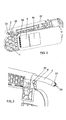
- Figures 1A and 1 B show an isometric view of a sun visor from its frontal side at unextended and extended lowered use position. The sun visor includes a mirror with sliding cover as an example not being restrictive, and might also include a mirror without cover or a rotatory cover.
- Figure 2 shows the sun visor interior with the body cover removed. Elements shown are:
-
Racket 1. Structural plastic element that forms the internal structure of the sun visor -
Pivot rod 2. Plastic element, which allows longitudinally extension of sun visor and rotation from raised storage to lowered use position. Besides, this allows lateral rotation for side protection. The pivot rod is jointly fixed to a slide and a guide channel is conformed into the racketsun visor structure 1. -
Tube 4. Hollow metal element for housing electrical lead and for helping slide guidance when extension movement -
Slide 5. Plastic part fixed to thepivot rod 2 which slides along the tube in the racket. - Spring. Elastic metal element which guarantees constant pressure around the pivot rod to set sun visor use positions.
- Arm support. The sun visor is hooked to the centre of the headliner and is released therefrom to carry out side protection.
- Distributor. Metal zone, which distributes power supply to electrical fittings.
- Mirror Unit. Mirror and plastic support for
mirror 9 which includes a slidingcover 91 and electrical elements to allow lighting command withlamps 92 at the headliner or in the mirror unit itself. - Figure 3 shows a detail of the
pivot rod end 21. Thepivot rod 2 is moulded around a metal tube insert. This tube is hollow to let the conductor or electrical lead 3 run in, being the conductor a flexible tape, a kind of flexible flat cable (FFC) or flexible printed circuit (FPC) including tracks and adaptable to curve from a power supply inlet to electrical fittings. - Figure 4 shows a detail of the
pivot rod 2. Micro-switches are devices that break an electrical circuit and, thus, activate electrical fittings. Thefirst micro-switch 6 at the top andpivot rod 2 end commands mirror lighting when thesun visor 1 leaves the folded storage position. Thesecond micro-switch 90 at the bottom commands mirror lighting when themirror cover 91 is manipulated. Themicro-switches - Lighting possibilities are:
Sun visor position First micro-switch Pivot rod Mirror cover Position Second micro-switch Mirror cover LIGHT Storage/Folded Open Closed Open OFF Use Closed Closed Open OFF Storage/Folded Open Open Closed OFF Use Closed Open Closed ON - Figure 5 shows slide details with the tube or conductor housing means 4, and the
pivot rod 2. The tube or conductor housing means 4 are opened to allow assembly of the conductor 3 that is, the flexible tape (FFC or FPC). At the second pivot rod end 22 a flange orflap 7 is appreciated, which acts as push to thenearest micro-switch 6. - Figure 6 shows a detail of the slide or sliding guiding means 5. The slide slips in the racket and along the tube or conductor housing means 4 and is joint to the
pivot rod 2 and the housing spring. - Figure 7 shows a remote control unit detail, for instance a domotic "home link" module 8. Power supply is provided by means of a connector.
characterized in that:
Claims (10)
- A sliding sun visor having:a pivot rod (2) having
a first end (21) arranged to be articulated to a headliner of a vehicle,
a second end (22) opposite to the first end (21) and
a hollow space (20) extending from the first end (21) to the second end (22);a sun visor structure (1) coupled to the pivot rod (2) in a manner so as to enable the sun visor structure (1) to be placed in a use-position selected from folded position, most pivoted and/or extended use-position and intermediate positions thereof, by pivoting around and sliding along said pivot rod (2);a conductor (3) for supplying power to at least one electrical device included in the sun visor structure (1), said conductor (3) having:the sun visor structure (1) comprising conductor housing means (4) for housing the second portion of the conductor, said conductor housing means (4) being parallel to the pivot rod (2);a first portion defined between the first end (21) of the pivot rod (2) and the second end (22) of the pivot rod (2), said first portion being housed in the hollow space (20) of the pivot rod (2) anda second portion having at least a length to enable the sun visor structure (1) be positioned in the most extended use-position;
characterized in that:the conductor housing means (4) are provided with a longitudinal groove (40)the conductor (3) comprises continuous conductor cables from the first end to the at least one electrical device;the conductor (3) is transversally folded. - The sliding sun visor of claim 1 further comprising sliding guiding means (5) fixed to the pivot rod (2) for guiding a sliding movement of the sun visor structure (1) along the pivot rod (2), the sliding guiding means (5) being in turn guided in the sliding movement of the sun visor structure (1) by the conductor housing means (4).
- The sliding sun visor of claim 2, wherein the conductor (3) is a flexible tape.
- The sliding sun visor of claim 3, wherein the flexible tape is a flexible printed circuit.
- The sliding sun visor of claim 1, wherein the conductor housing means (4) has an essentially U-shaped cross section.
- The sliding sun visor of claim 5, wherein the sliding guiding means (5) has a protuberance (50) for matching the longitudinal groove (40) of the conductor housing means (4) to prevent relative turning therebetween.
- The sliding sun visor of claim 1, further comprising a first microswitch (6) for detecting a pivoted sun visor structure (1) use-position.
- The sliding sun visor of claim 7, wherein the pivot rod (2) comprises a flap (7) for activating the first microswitch (6).
- The sliding sun visor of claim 1 further comprising a domotic module (8).
- The sliding sun visor of any of claims 7-9 further comprising:a vanity mirror (9) provided with a cover (91);a second microswitch (90) for detecting the cover (91) position;lighting means (92) for lighting the vanity mirror (9) according to the state of the first microswitch (6) and the state of the second microswitch (90).
Priority Applications (5)
| Application Number | Priority Date | Filing Date | Title |
|---|---|---|---|
| DE602004016869T DE602004016869D1 (en) | 2004-11-30 | 2004-11-30 | Sliding sun visor |
| EP04078253A EP1661744B1 (en) | 2004-11-30 | 2004-11-30 | Sliding sun visor |
| ES04078253T ES2311132T3 (en) | 2004-11-30 | 2004-11-30 | SLIDING PARASOL. |
| US11/261,501 US7384088B2 (en) | 2004-11-30 | 2005-10-31 | Sliding sun visor |
| CNA2005101271001A CN1803485A (en) | 2004-11-30 | 2005-11-30 | Sliding sun visor |
Applications Claiming Priority (1)
| Application Number | Priority Date | Filing Date | Title |
|---|---|---|---|
| EP04078253A EP1661744B1 (en) | 2004-11-30 | 2004-11-30 | Sliding sun visor |
Publications (2)
| Publication Number | Publication Date |
|---|---|
| EP1661744A1 true EP1661744A1 (en) | 2006-05-31 |
| EP1661744B1 EP1661744B1 (en) | 2008-10-01 |
Family
ID=34928697
Family Applications (1)
| Application Number | Title | Priority Date | Filing Date |
|---|---|---|---|
| EP04078253A Expired - Lifetime EP1661744B1 (en) | 2004-11-30 | 2004-11-30 | Sliding sun visor |
Country Status (5)
| Country | Link |
|---|---|
| US (1) | US7384088B2 (en) |
| EP (1) | EP1661744B1 (en) |
| CN (1) | CN1803485A (en) |
| DE (1) | DE602004016869D1 (en) |
| ES (1) | ES2311132T3 (en) |
Families Citing this family (21)
| Publication number | Priority date | Publication date | Assignee | Title |
|---|---|---|---|---|
| DE102004060758B4 (en) * | 2004-12-15 | 2013-08-01 | Johnson Controls Interiors Gmbh & Co. Kg | Mirror module for a sun visor for a vehicle, sun visor for a motor vehicle |
| US20070187976A1 (en) * | 2005-04-01 | 2007-08-16 | Johnson Controls Technology Company | Visor and method for making a visor |
| JP2009126445A (en) * | 2007-11-27 | 2009-06-11 | Kyowa Sangyo Kk | Vehicle sun visor |
| DE502008000304D1 (en) * | 2008-03-25 | 2010-02-25 | Smr Patents Sarl | Sun visor with plastic mirror |
| US20110062741A1 (en) * | 2009-03-09 | 2011-03-17 | Ilo Kristo Xhunga | Palm-like Sun Visor |
| FR2948068B1 (en) * | 2009-07-15 | 2012-10-26 | Peugeot Citroen Automobiles Sa | DEVICE FOR OCCULATING A VEHICLE PAVILION WITH A GUIDE (S) WITH INTEGRATED LIGHT (S) |
| CN102072813B (en) * | 2011-01-20 | 2012-02-22 | 宁波市阳光汽车配件有限公司 | Automobile sunshade plate distortion test device |
| US8556325B2 (en) | 2011-09-20 | 2013-10-15 | Irvin Automotive Products, Inc. | Sliding visor |
| DE102013209797A1 (en) * | 2012-05-30 | 2013-12-05 | Kyowa Sangyo Co., Ltd. | SUNSHADE FOR A VEHICLE |
| US10737559B2 (en) | 2014-12-16 | 2020-08-11 | Irvin Automotive Products, LLC | Visor |
| CN105082949A (en) * | 2015-08-31 | 2015-11-25 | 江阴万事兴汽车部件股份有限公司 | Automobile sun shield with cosmetic mirror |
| US20170240103A1 (en) | 2016-02-23 | 2017-08-24 | Motus Integrated Technologies | Vehicle sun visor assembly having an electrical system |
| US10377213B2 (en) | 2017-04-20 | 2019-08-13 | Daimay North America Automotive Engineering Technology, Inc. | Vanity mirror assembly for a vehicle sun visor |
| US10532635B2 (en) * | 2017-07-24 | 2020-01-14 | Cecil W. Mueller | Attachable sun visor system |
| US10688850B2 (en) | 2018-03-13 | 2020-06-23 | Irvin Automotive Products, LLC | Sliding visor |
| US10737558B2 (en) | 2018-06-04 | 2020-08-11 | Mark Stevens | Adjustable vehicle visor |
| KR102055503B1 (en) * | 2018-06-14 | 2019-12-12 | 주식회사 동원테크 | Sunvisors for automobiles |
| US10870337B2 (en) | 2019-02-28 | 2020-12-22 | Irvin Automotive Products, LLC | Thin visor |
| US10864804B2 (en) | 2019-02-28 | 2020-12-15 | Irvin Automotive Products, LLC | Sliding thin visor |
| CN209650011U (en) * | 2019-03-22 | 2019-11-19 | 江阴万事兴汽车部件股份有限公司 | Band garage switch lever formula sunshading board |
| CN115723696B (en) * | 2022-11-04 | 2024-09-06 | 中国第一汽车股份有限公司 | Sun-shading board cosmetic mirror system for vehicle and control method |
Citations (8)
| Publication number | Priority date | Publication date | Assignee | Title |
|---|---|---|---|---|
| EP0525452A1 (en) * | 1991-07-30 | 1993-02-03 | Gebr. Happich GmbH | Sun visor for vehicles |
| US5365416A (en) * | 1992-04-15 | 1994-11-15 | Crotty Corporation | Sun visor with integral core |
| US5560704A (en) * | 1993-11-17 | 1996-10-01 | Prince Corporation | Covered vanity mirror hinge assembly |
| JPH11321309A (en) * | 1998-05-13 | 1999-11-24 | Kasai Kogyo Co Ltd | Sliding sun visor |
| US6220644B1 (en) * | 1999-03-10 | 2001-04-24 | Lear Automotive Dearborn, Inc. | Visor assembly |
| EP1142736A1 (en) * | 2000-04-05 | 2001-10-10 | Johnson Controls Interiors GmbH & Co. KG | Sunvisor for vehicles |
| JP2004009883A (en) * | 2002-06-06 | 2004-01-15 | Kasai Kogyo Co Ltd | Sliding type sun visor |
| JP2004034810A (en) * | 2002-07-02 | 2004-02-05 | Kyowa Sangyo Kk | Sun visor for vehicles |
Family Cites Families (5)
| Publication number | Priority date | Publication date | Assignee | Title |
|---|---|---|---|---|
| US6131985A (en) | 1995-08-14 | 2000-10-17 | Crotty Corporation | Modular sun visor assembly and method of assembling a sun visor |
| US5653490A (en) | 1996-04-12 | 1997-08-05 | Prince Corporation | Sliding visor |
| US6139083A (en) | 1998-04-24 | 2000-10-31 | Lear-Donnelly Overhead Systems, Llc | Sliding core visor |
| DE10017047A1 (en) | 2000-04-05 | 2001-10-11 | Johnson Contr Interiors Gmbh | Sunshade for vehicle has electrical lighting device switch, remote control unit for automatic garage door opener, cable containing conducting wire(s) with excess for sunshade movement |
| JP4373019B2 (en) | 2001-01-17 | 2009-11-25 | 株式会社ネオックスラボ | Vehicle sun visor |
-
2004
- 2004-11-30 EP EP04078253A patent/EP1661744B1/en not_active Expired - Lifetime
- 2004-11-30 ES ES04078253T patent/ES2311132T3/en not_active Expired - Lifetime
- 2004-11-30 DE DE602004016869T patent/DE602004016869D1/en not_active Expired - Lifetime
-
2005
- 2005-10-31 US US11/261,501 patent/US7384088B2/en not_active Expired - Fee Related
- 2005-11-30 CN CNA2005101271001A patent/CN1803485A/en active Pending
Patent Citations (8)
| Publication number | Priority date | Publication date | Assignee | Title |
|---|---|---|---|---|
| EP0525452A1 (en) * | 1991-07-30 | 1993-02-03 | Gebr. Happich GmbH | Sun visor for vehicles |
| US5365416A (en) * | 1992-04-15 | 1994-11-15 | Crotty Corporation | Sun visor with integral core |
| US5560704A (en) * | 1993-11-17 | 1996-10-01 | Prince Corporation | Covered vanity mirror hinge assembly |
| JPH11321309A (en) * | 1998-05-13 | 1999-11-24 | Kasai Kogyo Co Ltd | Sliding sun visor |
| US6220644B1 (en) * | 1999-03-10 | 2001-04-24 | Lear Automotive Dearborn, Inc. | Visor assembly |
| EP1142736A1 (en) * | 2000-04-05 | 2001-10-10 | Johnson Controls Interiors GmbH & Co. KG | Sunvisor for vehicles |
| JP2004009883A (en) * | 2002-06-06 | 2004-01-15 | Kasai Kogyo Co Ltd | Sliding type sun visor |
| JP2004034810A (en) * | 2002-07-02 | 2004-02-05 | Kyowa Sangyo Kk | Sun visor for vehicles |
Non-Patent Citations (2)
| Title |
|---|
| PATENT ABSTRACTS OF JAPAN vol. 2000, no. 02 29 February 2000 (2000-02-29) * |
| PATENT ABSTRACTS OF JAPAN vol. 2003, no. 12 5 December 2003 (2003-12-05) * |
Also Published As
| Publication number | Publication date |
|---|---|
| US20060113819A1 (en) | 2006-06-01 |
| ES2311132T3 (en) | 2009-02-01 |
| EP1661744B1 (en) | 2008-10-01 |
| US7384088B2 (en) | 2008-06-10 |
| CN1803485A (en) | 2006-07-19 |
| DE602004016869D1 (en) | 2008-11-13 |
Similar Documents
| Publication | Publication Date | Title |
|---|---|---|
| EP1661744B1 (en) | Sliding sun visor | |
| EP1731341B1 (en) | Internal sunshade for transparent roofs of automobiles | |
| US8042664B2 (en) | Electrical cable retractor assembly for a movable window | |
| US4422687A (en) | Sliding roof panel assembly | |
| US8061757B1 (en) | Force assist for sunshade closing slide mechanism | |
| EP2628619A2 (en) | Electric connection structure for a sunroof device | |
| US5707102A (en) | Automotive sun roof device | |
| US9216631B2 (en) | Roof system for a motor vehicle | |
| USH1834H (en) | Sun visor assembly | |
| JP2007513271A (en) | Automotive window regulator with floating window carrier | |
| CN116964293A (en) | Structural components of adjusting devices for motor vehicles | |
| EP0919415B1 (en) | An open roof construction for a vehicle | |
| US11447995B2 (en) | Device for moving a door leaf | |
| US4379586A (en) | Sliding roof panel assembly | |
| CN108312817B (en) | Structure of electric sunshade and skylight | |
| US7393048B2 (en) | Sunshade panel apparatus | |
| CA2465821C (en) | A sunroof with lead screw drive element | |
| US11952820B1 (en) | Slider window assembly with movable panel drive system | |
| JP2005522369A (en) | Roof assembly for vehicle | |
| MXPA05012426A (en) | Sliding sun visor | |
| KR20060030464A (en) | Shelf assembly of vehicle | |
| JP2002166727A (en) | Sunroof equipment | |
| DE102021214299B4 (en) | Shading device for a window section of a motor vehicle | |
| KR100440286B1 (en) | sun roof for vehicle | |
| JPH043332B2 (en) |
Legal Events
| Date | Code | Title | Description |
|---|---|---|---|
| PUAI | Public reference made under article 153(3) epc to a published international application that has entered the european phase |
Free format text: ORIGINAL CODE: 0009012 |
|
| AK | Designated contracting states |
Kind code of ref document: A1 Designated state(s): AT BE BG CH CY CZ DE DK EE ES FI FR GB GR HU IE IS IT LI LU MC NL PL PT RO SE SI SK TR |
|
| AX | Request for extension of the european patent |
Extension state: AL HR LT LV MK YU |
|
| 17P | Request for examination filed |
Effective date: 20061122 |
|
| AKX | Designation fees paid |
Designated state(s): DE ES FR |
|
| GRAP | Despatch of communication of intention to grant a patent |
Free format text: ORIGINAL CODE: EPIDOSNIGR1 |
|
| GRAS | Grant fee paid |
Free format text: ORIGINAL CODE: EPIDOSNIGR3 |
|
| GRAA | (expected) grant |
Free format text: ORIGINAL CODE: 0009210 |
|
| AK | Designated contracting states |
Kind code of ref document: B1 Designated state(s): DE ES FR |
|
| REF | Corresponds to: |
Ref document number: 602004016869 Country of ref document: DE Date of ref document: 20081113 Kind code of ref document: P |
|
| REG | Reference to a national code |
Ref country code: ES Ref legal event code: FG2A Ref document number: 2311132 Country of ref document: ES Kind code of ref document: T3 |
|
| PGFP | Annual fee paid to national office [announced via postgrant information from national office to epo] |
Ref country code: ES Payment date: 20081113 Year of fee payment: 5 |
|
| PLBE | No opposition filed within time limit |
Free format text: ORIGINAL CODE: 0009261 |
|
| STAA | Information on the status of an ep patent application or granted ep patent |
Free format text: STATUS: NO OPPOSITION FILED WITHIN TIME LIMIT |
|
| 26N | No opposition filed |
Effective date: 20090702 |
|
| REG | Reference to a national code |
Ref country code: ES Ref legal event code: FD2A Effective date: 20110325 |
|
| PG25 | Lapsed in a contracting state [announced via postgrant information from national office to epo] |
Ref country code: ES Free format text: LAPSE BECAUSE OF NON-PAYMENT OF DUE FEES Effective date: 20110314 |
|
| PG25 | Lapsed in a contracting state [announced via postgrant information from national office to epo] |
Ref country code: ES Free format text: LAPSE BECAUSE OF NON-PAYMENT OF DUE FEES Effective date: 20091201 |
|
| REG | Reference to a national code |
Ref country code: FR Ref legal event code: PLFP Year of fee payment: 12 |
|
| PGFP | Annual fee paid to national office [announced via postgrant information from national office to epo] |
Ref country code: DE Payment date: 20151127 Year of fee payment: 12 |
|
| PGFP | Annual fee paid to national office [announced via postgrant information from national office to epo] |
Ref country code: FR Payment date: 20151029 Year of fee payment: 12 |
|
| REG | Reference to a national code |
Ref country code: DE Ref legal event code: R119 Ref document number: 602004016869 Country of ref document: DE |
|
| REG | Reference to a national code |
Ref country code: DE Ref legal event code: R082 Ref document number: 602004016869 Country of ref document: DE Representative=s name: SCHMITT-NILSON SCHRAUD WAIBEL WOHLFROM PATENTA, DE |
|
| REG | Reference to a national code |
Ref country code: FR Ref legal event code: ST Effective date: 20170731 |
|
| PG25 | Lapsed in a contracting state [announced via postgrant information from national office to epo] |
Ref country code: FR Free format text: LAPSE BECAUSE OF NON-PAYMENT OF DUE FEES Effective date: 20161130 |
|
| PG25 | Lapsed in a contracting state [announced via postgrant information from national office to epo] |
Ref country code: DE Free format text: LAPSE BECAUSE OF NON-PAYMENT OF DUE FEES Effective date: 20170601 |