EP1659751A2 - OFDM Wireless receiver - Google Patents
OFDM Wireless receiver Download PDFInfo
- Publication number
- EP1659751A2 EP1659751A2 EP05251781A EP05251781A EP1659751A2 EP 1659751 A2 EP1659751 A2 EP 1659751A2 EP 05251781 A EP05251781 A EP 05251781A EP 05251781 A EP05251781 A EP 05251781A EP 1659751 A2 EP1659751 A2 EP 1659751A2
- Authority
- EP
- European Patent Office
- Prior art keywords
- intermediate frequency
- signal
- frequency
- frequency signal
- sampling
- Prior art date
- Legal status (The legal status is an assumption and is not a legal conclusion. Google has not performed a legal analysis and makes no representation as to the accuracy of the status listed.)
- Withdrawn
Links
Images




Classifications
-
- H—ELECTRICITY
- H04—ELECTRIC COMMUNICATION TECHNIQUE
- H04L—TRANSMISSION OF DIGITAL INFORMATION, e.g. TELEGRAPHIC COMMUNICATION
- H04L27/00—Modulated-carrier systems
- H04L27/26—Systems using multi-frequency codes
- H04L27/2601—Multicarrier modulation systems
- H04L27/2647—Arrangements specific to the receiver only
Definitions
- the present invention relates to an OFDM wireless receiver and more particularly to an OFDM wireless receiver which prevents degradation of reception quality by determining an intermediate frequency such that the results of under-sampling of the intermediate frequency signal are folded back into a subcarrier band which is not used in OFDM communication.
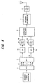
- Fig. 4 is an example of configuration of an OFDM (Orthogonal Frequency Division Multiplex) transmission device.
- a baseband signal processing part 1 executes baseband signal processing such as adding error correction/detection codes to the signal to be transmitted, interleaving, multilevel modulation and code spreading.
- a serial/parallel converting device (S/P convertor) 2 converts the processing results (transmission data) of the baseband signal processing part 1 into N complex components, an IFFT part (inverse fast Fourier transform device) 3, performing IFFT processing of the N complex components as N subcarrier components, transforms them into a real number part discrete time signal I(t) and an imaginary number part discrete time signal Q(t) and outputs them.
- each subcarrier of the IFFT part 3 becomes a complex sine wave with a frequency of an integer multiple of a base frequency of 1/N of the FFT sampling frequency fs where the integer is 1, 2,... N.
- fs is the FFT sampling frequency and is also the sampling frequency of the AD converter described later.
- the IFFT part 3 by summing all the complex sine wave signals generated by these N subcarriers, outputs the real number part discrete time signal I(t) and the imaginary number part discrete time signal Q(t).
- Fig. 6 is the frequency spectrum in a case where the subcarriers are selected and used as shown in Fig. 5.
- Digital-to-analog converters (DA converters) 4a and 4b perform DA conversion and convert the discrete time signals I(t) and Q(t), which were IFFT processed, into analog electric signals.
- LFPs 5a and 5b perform band limiting, extract analog baseband signals of the desired band and output them to an quadrature modulator 6.
- the quadrature modulator 6 executes an quadrature modulation by multiplying the real number part I(t) and imaginary number part Q(t) by the intermediate frequency sine waves and cosine waves generated from a local oscillator (not shown in the figure).
- BPF band pass filter
- the subcarrier f 0 corresponding to the direct current component is not used is to prevent the local leak that occurs in frequency conversion which uses analog MIX from interfering with the subcarrier f 0 .
- the reason subcarriers near -fs/2 and +fs/2 are not used is because if they were used, the low-pass filters 5a and 5b would require a steep slope characteristic.
- the output signals of DA converters 4a and 4b are input to the filters 5a and 5b so as to separate these baseband signals.
- Fig. 7 shows a configuration of an OFDM receiver comprising a heterodyne receiver configuration.
- a low-noise amplifier 11 amplifies the RF signal of frequency fc received by the antenna.
- a mixer 12 generates an intermediate frequency signal of frequency f IF , by mixing a local signal (local oscillation signal) generated from a local oscillator 13 and having a frequency of (fc - f IF ) with the RF signal.
- An IF filter 14 passes the signal component of the intermediate frequency band, and a variable gain amplifier 15 amplifies the intermediate frequency signal and inputs it to an quadrature demodulator 16.
- a local oscillator 16a generates a local signal of the same frequency as the intermediate frequency f IF
- a phase shifter 16b inputs a local cosine wave and sine wave, the phases of which differ by 90°, to multipliers (mixers) 16c and 16d.
- Each of the mixers 16c and 16d demodulates the complex signal of the baseband (real number part and imaginary number part) by multiplying the intermediate frequency signal by the cosine wave and sine wave, and inputs the results of the demodulation to low-pass filters 17a and 17b for erasing aliasing distortion.
- the low-pass filters 17a and 17b basically pass the baseband signals (main signals) and input them to AD converters 18a and 18b.
- the AD converters 18a and 18b sample each component of the baseband complex signal respectively at the frequency fs and input them to an FFT part 19 of size N.
- the FFT part 19 performs FFT processing using N complex signals and outputs N' subcarrier signal components.
- a P/S converter 20 converts the N' subcarrier signal components into serial complex data and inputs the data into a baseband processor not shown in the figure.
- the mixers 16c and 16d of the quadrature demodulator 16 there is a limit to the isolation amount and small amount of the local signal leaks into the main signal component.
- the low-pass filters 17a and 17b are necessary to eliminate the local leak components.
- band ratio in configuring the IF filter 14, and it is necessary to increase the intermediate frequency f IF .
- the "band ratio" is the ratio of bandwidth to the central frequency and, for performance reasons, it is necessary to make the band ratio less than a specified value.
- the low-pass filters 17a and 17b cannot block up to high bands. This is because, while the chip components which constitute the low-pass filter operate normally when the frequency is low, as the frequency rises they show characteristics different from the pure R, L, and C due to parasitic components. For example, even if a filter composed of coil L and condenser C, at high frequency the coil L operates as a capacitor and deteriorates characteristic of the filter.
- Fig. 8 shows an example of the frequency characteristic in the case where a low-pass filter is composed of chip components.
- the low-pass filter shows exactly a low-pass characteristic, but its characteristic in the region where the frequency is sufficiently high deteriorates as shown in (B) and it does not function adequately as a correct low-pass filter. In this way, a low-pass filter composed of low-cost chip components cannot block the high frequency components.
- Fig. 9 and Fig. 10 are drawings which explain this problem.
- Fig. 9 is the spectrum of the signal input to AD converters 18a and 18b when the local signal is leaking from the low-pass filters 17a and 17b.
- S is the spectrum of the main signal
- S1 and S2 are the spectrums of the local leak component.
- the local frequency (intermediate frequency) f IF is a frequency far higher than the sampling frequency fs. If a leak signal having this intermediate frequency f IF is sampled at a frequency fs which is lower than that intermediate frequency (this is called "under-sampling"), the spectrum of the leak signal overlies on the main signal spectrum S as the image spectrums S3 and S4, as shown in Fig. 10.
- an object of the present invention is to prevent degradation of reception quality of the main signal by adapting a predetermined frequency as an intermediate frequency.
- a further object of the present invention is to prevent degradation of the reception quality of the main signal even if the low-pass filter is composed of a low-cost L and C configuration.
- a further object of the present invention is to prevent degradation of the reception quality of the main signal even if an intermediate frequency local signal leaks from the low-pass filter.
- an OFDM wireless receiver comprising an intermediate frequency signal generator for generating an intermediate frequency signal in such a way that the spectrum when the intermediate frequency signal is under-sampled at a sampling frequency appears in a subcarrier band not used in OFDM transmission.
- the above-mentioned intermediate frequency signal generator determines the intermediate frequency in such a way that the remainder obtained by dividing the intermediate frequency by the sampling frequency is a frequency within a subcarrier band not used in OFDM transmission.
- the above-mentioned intermediate frequency signal generator determines the intermediate frequency in such a way that the intermediate frequency is a multiple of the sampling frequency.
- the OFDM wireless receiver in addition to the above-mentioned intermediate frequency signal generator, comprises an quadrature demodulator for performing quadrature demodulation processing on the intermediate frequency signal and demodulating the baseband signal, a low-pass filter for cutting a high frequency component of the signal outputted from that quadrature demodulator, and an AD converter for sampling the output signal of that low-pass filter and converting it to a digital signal, wherein the intermediate frequency signal generator matches the local oscillation frequency of the quadrature demodulator to the intermediate frequency.
- an OFDM wireless receiver comprising a heterodyne receiver for demodulating a baseband signal from an intermediate frequency signal, a low-pass filter for cutting a high frequency component of the signal outputted from the heterodyne receiver, an AD converter for sampling the output signal of the low-pass filter at a sampling frequency and converting the sampled signal to a digital signal, a Fourier transformer for performing a Fourier transform on the digital signal obtained by the AD converter, and an intermediate frequency signal generator for generating the intermediate frequency signal in such a way that the spectrum when the intermediate frequency signal inputted to the above-mentioned AD converter is under-sampled appears in a subcarrier band not used in OFDM transmission.
- the above-mentioned intermediate frequency signal generator determines the intermediate frequency so that the frequency of the remainder obtained by dividing the intermediate frequency by the sampling frequency is within a subcarrier band not used in the above-mentioned OFDM transmission. Alternatively, the above-mentioned intermediate frequency signal generator determines that intermediate frequency so that the intermediate frequency is a multiple of the sampling frequency.
- the intermediate frequency signal is generated in such a way that the spectrum when the intermediate frequency signal is under-sampled appears in a subcarrier band not used in OFDM transmission, the reception quality of the main signal does not degrade even if an intermediate frequency local signal leaks from the low-pass filter.
- a heterodyne receiving portion demodulates a baseband signal from an intermediate frequency signal.
- a low-pass filter cuts the high frequency component of the signal outputted from that heterodyne receiver.
- An AD converter samples the output signal of that low-pass filter and converts it to a digital signal.
- a Fourier transformer performs a Fourier transform on the digital signal obtained by the AD converter.
- An intermediate frequency signal generator generates the intermediate frequency signal so that the spectrum of the signal obtained by under-sampling the intermediate frequency signal at the AD converter, appears in a subcarrier band which is not used in OFDM transmission.
- the intermediate frequency signal generator determines the intermediate frequency so that the frequency of the remainder obtained by dividing the intermediate frequency by the sampling frequency, becomes within a sampling band not used in OFDM transmission.
- the intermediate frequency generator determines the intermediate frequency so that the intermediate frequency becomes a multiple of the sampling frequency.
- Fig. 1 is a block diagram of an OFDM receiver according to the present invention.
- a low noise amplifier (LNA) 51 amplifies an RF signal of frequency fc received by an antenna.
- a mixer 52 generates an intermediate frequency signal of frequency f IF by mixing a local signal of frequency (fc - f IF ), which is generated from a local oscillator 53, with the RF signal, and an IF filter 54 passes the intermediate frequency band signal component.
- a variable gain amplifier 55 amplifies the intermediate frequency signal and inputs it to an quadrature demodulator 56.
- a local oscillator 56a generates a local signal (local oscillation signal) of the same frequency as the intermediate frequency f IF , a phase shifter 56b inputs a local cosine wave and sine wave, the phases of which differ by 90°, to multipliers (mixers) 56c and 56d.
- Each of the mixers 56c and 56d demodulates the complex signal of the baseband(real number part and imaginary number part) by multiplying the intermediate frequency signal by the cosine wave and sine wave and inputs the results of the demodulation to low-pass filters 57a and 57b.
- the low-pass filters 57a and 57b pass the baseband signals (main signals) and input them to AD converters 58a and 58b.
- the AD converters 58a and 58b sample each component of the baseband complex signal respectively at the frequency fs, convert them to digital signals, and input them to an FFT part 59 of size N.
- the FFT part 59 performs FFT processing on N complex signals and outputs N' subcarrier signal components C 1 through C N' .
- a P/S converter (not shown in the figure) converts the N' subcarrier signal components C 1 through C N' into serial complex data and inputs the data into a baseband processor (not shown in the figure).
- An intermediate frequency determining part 60 in order to control the intermediate frequency f IF so that the spectrum when the intermediate frequency signal inputted to the AD converters 58a and 58b is under-sampled therein, appears in a subcarrier band not used in OFDM transmission, instructs the local oscillator 53 to oscillate at a frequency of (fc - f IF ) and also instructs the local oscillator 56a to oscillate at a frequency of f IF .
- the local oscillator 53 generates a local signal with a frequency of (fc - f IF ) and the local oscillator 56a generates a local signal with a frequency of f IF .
- the intermediate frequency determining part 60 by controlling the local oscillator 53, generates an intermediate frequency signal of intermediate frequency f IF from the mixer 52 and also, by controlling the local oscillator 56a, generates a local signal of intermediate frequency f IF . Further, a control of this intermediate frequency signal generation may also be possible without using the intermediate frequency determining part. That is, without using the intermediate frequency determining part 60, the local oscillator 53 is adjusted to generate in a fixed manner a local signal with a frequency of (fc - f IF ) and the local oscillator 56a adjusted to generate in a fixed manner a local signal with a frequency of f IF .
- a configuration incorporating both the intermediate frequency determining part 60 and the local oscillator 53 (and also the mixer 52) is regarded as an intermediate frequency generating part for producing the intermediate frequency f IF .
- the local oscillator 53 (and also the mixer 52) can be considered to be the intermediate frequency generating part.
- FIG. 2 is an explanatory drawing of the first intermediate frequency determining method by means of the intermediate frequency determining part 60.
- A shows the spectrum S of the OFDM signal (main signal) in a case where the sampling frequency is fs.
- the spectrum for these subcarriers becomes 0.
- B shows the spectrum of the signal inputted to the AD converters 58a and 58b when the local signal having a inermediated frequency f IF is leaking from the low-pass filters 57a and 57b.
- S is the spectrum of the main signal
- S1 and S2 are the spectrums of the local leak component.
- C shows the spectrum S of the OFDM signal and spectrums S3 and S4 in a case where the local signal having the intermediate frequency is under-sampled in the AD converters and the spectrums S3 and S4 of the under-sampled signal appear in the subcarrier bands -fs/2 to -fm and fm to fs/2 which are not used for OFDM transmission.
- the intermediate frequency determining part 60 In order to produce the spectrums S3 and S4 as shown in(C), the intermediate frequency determining part 60 must determine the intermediate frequency f IF so that the remainder, when the intermediate frequency f IF is divided by the sampling frequency fs, is a frequency in the subcarrier bands -fs/2 to -fm and fm to fs/2 which are not used in OFDM transmission.
- f IF (mod f s ) is the remainder when f IF is divided by f s .
- FIG. 3 is an explanatory drawing of the second intermediate frequency determining method by means of the intermediate frequency determining part 60.
- (A) shows the spectrum S of the OFDM signal (main signal) in a case where the sampling frequency is fs.
- the spectrum for these subcarriers becomes 0.
- (B) shows the spectrum of the signal inputted to the AD converters 58a and 58b when the local signal having a intermediate frequency f IF is leaking from the low-pass filters 57a and 57b, S is the spectrum of the main signal, and S1 and S2 are the spectrums of the local leak component.
- the intermediate frequency signal is generated with the intermediate frequency determined in the above manner, the spectrum when the intermediate frequency signal is under-sampled appears in a subcarrier band which is not used in OFDM transmission.
- a special filter such as a high-priced dielectric filter need not be used, and degradation of reception quality of the main signal can be prevented even if the low-pass filter is a low-cost one composed of L and C. Also, as a result of this, it is possible to achieve lower cost, smaller volume, and a reduction in circuit scale.
Landscapes
- Engineering & Computer Science (AREA)
- Computer Networks & Wireless Communication (AREA)
- Signal Processing (AREA)
- Superheterodyne Receivers (AREA)
Abstract
Description
- The present invention relates to an OFDM wireless receiver and more particularly to an OFDM wireless receiver which prevents degradation of reception quality by determining an intermediate frequency such that the results of under-sampling of the intermediate frequency signal are folded back into a subcarrier band which is not used in OFDM communication.
- Fig. 4 is an example of configuration of an OFDM (Orthogonal Frequency Division Multiplex) transmission device.
- A baseband
signal processing part 1 executes baseband signal processing such as adding error correction/detection codes to the signal to be transmitted, interleaving, multilevel modulation and code spreading. A serial/parallel converting device (S/P convertor) 2 converts the processing results (transmission data) of the basebandsignal processing part 1 into N complex components, an IFFT part (inverse fast Fourier transform device) 3, performing IFFT processing of the N complex components as N subcarrier components, transforms them into a real number part discrete time signal I(t) and an imaginary number part discrete time signal Q(t) and outputs them. If N is the FFT (fast Fourier transform) size, each subcarrier of theIFFT part 3 becomes a complex sine wave with a frequency of an integer multiple of a base frequency of 1/N of the FFT sampling frequency fs where the integer is 1, 2,... N. fs is the FFT sampling frequency and is also the sampling frequency of the AD converter described later. The IFFTpart 3, by summing all the complex sine wave signals generated by these N subcarriers, outputs the real number part discrete time signal I(t) and the imaginary number part discrete time signal Q(t). - Actuality, as shown in Fig. 5, in OFDM transmission, the number N'of subcarriers (=the number of terminals for which 0 is not inputted) is made to be fewer than FFT size N. In other words, by not using subcarrier fo which corresponds to the direct current component and subcarriers near -fs/2 or +fs/2, reliability is improved and the processing of RF transmission signals becomes easier. Fig. 6 is the frequency spectrum in a case where the subcarriers are selected and used as shown in Fig. 5.
Digital-to-analog converters (DA converters) 4a and 4b perform DA conversion and convert the discrete time signals I(t) and Q(t), which were IFFT processed, into analog electric signals. Due to the nature of the IFFT or DA conversion processing, higher harmonic components are included in the analog baseband signals obtained by the above processing. As a result, low-pass filters (LFPs) 5a and 5b perform band limiting, extract analog baseband signals of the desired band and output them to anquadrature modulator 6. Thequadrature modulator 6 executes an quadrature modulation by multiplying the real number part I(t) and imaginary number part Q(t) by the intermediate frequency sine waves and cosine waves generated from a local oscillator (not shown in the figure). Then they are frequency converted into RF frequency signals by a frequency up-converter 7, and after a band pass filter (BPF) 8 removes image components and unnecessary waves, such as spurious ones, occurring in the analog MIX (quadrature modulation and frequency conversion), they pass through a high-frequency amplifier and the like, not shown in the figures, and are transmitted from the antenna. - In the IFFT 3, one of the main reasons the subcarrier f0 corresponding to the direct current component is not used is to prevent the local leak that occurs in frequency conversion which uses analog MIX from interfering with the subcarrier f0. Likewise, the reason subcarriers near -fs/2 and +fs/2 are not used is because if they were used, the low-
pass filters DA converters filters noise amplifier 11 amplifies the RF signal of frequency fc received by the antenna. Amixer 12 generates an intermediate frequency signal of frequency fIF, by mixing a local signal (local oscillation signal) generated from alocal oscillator 13 and having a frequency of (fc - fIF) with the RF signal. AnIF filter 14 passes the signal component of the intermediate frequency band, and avariable gain amplifier 15 amplifies the intermediate frequency signal and inputs it to anquadrature demodulator 16. - In the
quadrature demodulator 16, alocal oscillator 16a generates a local signal of the same frequency as the intermediate frequency fIF, aphase shifter 16b inputs a local cosine wave and sine wave, the phases of which differ by 90°, to multipliers (mixers) 16c and 16d. Each of themixers pass filters pass filters AD converters AD converters FFT part 19 of size N. TheFFT part 19 performs FFT processing using N complex signals and outputs N' subcarrier signal components. A P/S converter 20 converts the N' subcarrier signal components into serial complex data and inputs the data into a baseband processor not shown in the figure. - In the
mixers quadrature demodulator 16, there is a limit to the isolation amount and small amount of the local signal leaks into the main signal component. The low-pass filters IF filter 14, and it is necessary to increase the intermediate frequency fIF. The "band ratio" is the ratio of bandwidth to the central frequency and, for performance reasons, it is necessary to make the band ratio less than a specified value. - On the other hand, the low-
pass filters - For this reason, in the past there has been the problem that if the intermediate frequency fIF became high, a low-pass filter composed of low-cost chip components could not be used, and instead it was necessary to use a special-purpose filter, such as a high-priced dielectric filter.
- Also, in the past, there was the problem that, if a low-pass filter was not configured precisely, the local leak component of the intermediate frequency would be under-sampled by the
AD converters - Fig. 9 and Fig. 10 are drawings which explain this problem. Fig. 9 is the spectrum of the signal input to
AD converters pass filters - With the foregoing in view, an object of the present invention is to prevent degradation of reception quality of the main signal by adapting a predetermined frequency as an intermediate frequency.
- A further object of the present invention is to prevent degradation of the reception quality of the main signal even if the low-pass filter is composed of a low-cost L and C configuration.
- A further object of the present invention is to prevent degradation of the reception quality of the main signal even if an intermediate frequency local signal leaks from the low-pass filter.
- The present invention achieves the above objects by an OFDM wireless receiver comprising an intermediate frequency signal generator for generating an intermediate frequency signal in such a way that the spectrum when the intermediate frequency signal is under-sampled at a sampling frequency appears in a subcarrier band not used in OFDM transmission. The above-mentioned intermediate frequency signal generator determines the intermediate frequency in such a way that the remainder obtained by dividing the intermediate frequency by the sampling frequency is a frequency within a subcarrier band not used in OFDM transmission. Alternatively, the above-mentioned intermediate frequency signal generator determines the intermediate frequency in such a way that the intermediate frequency is a multiple of the sampling frequency.
- Further, the OFDM wireless receiver, in addition to the above-mentioned intermediate frequency signal generator, comprises an quadrature demodulator for performing quadrature demodulation processing on the intermediate frequency signal and demodulating the baseband signal, a low-pass filter for cutting a high frequency component of the signal outputted from that quadrature demodulator, and an AD converter for sampling the output signal of that low-pass filter and converting it to a digital signal, wherein the intermediate frequency signal generator matches the local oscillation frequency of the quadrature demodulator to the intermediate frequency.
- The present invention achieves the above object by an OFDM wireless receiver comprising a heterodyne receiver for demodulating a baseband signal from an intermediate frequency signal, a low-pass filter for cutting a high frequency component of the signal outputted from the heterodyne receiver, an AD converter for sampling the output signal of the low-pass filter at a sampling frequency and converting the sampled signal to a digital signal, a Fourier transformer for performing a Fourier transform on the digital signal obtained by the AD converter, and an intermediate frequency signal generator for generating the intermediate frequency signal in such a way that the spectrum when the intermediate frequency signal inputted to the above-mentioned AD converter is under-sampled appears in a subcarrier band not used in OFDM transmission.
- The above-mentioned intermediate frequency signal generator determines the intermediate frequency so that the frequency of the remainder obtained by dividing the intermediate frequency by the sampling frequency is within a subcarrier band not used in the above-mentioned OFDM transmission. Alternatively, the above-mentioned intermediate frequency signal generator determines that intermediate frequency so that the intermediate frequency is a multiple of the sampling frequency.
- According to the present invention, because the intermediate frequency signal is generated in such a way that the spectrum when the intermediate frequency signal is under-sampled appears in a subcarrier band not used in OFDM transmission, the reception quality of the main signal does not degrade even if an intermediate frequency local signal leaks from the low-pass filter.
- Other features and advantages of the present invention will be apparent from the following descriptions taken in conjunction with the accompanying drawings.
-
- Fig. 1 is a block diagram of an OFDM receiver according to the present invention;
- Fig. 2 is an explanatory drawing of the first intermediate frequency determining method of the intermediate frequency determining part;
- Fig. 3 is an explanatory drawing of the second intermediate frequency determining method of the intermediate frequency determining part;
- Fig. 4 is a configuration of a conventional OFDM transmitter;
- Fig. 5 is a diagram for explaining OFDM size and the subcarriers which are not used during OFDM transmission;
- Fig. 6 is a frequency spectrum in a case where subcarriers have been selected as shown in Fig. 5;
- Fig. 7 is a an OFDM receiver comprising a conventional heterodyne receiving configuration;
- Fig. 8 is an example of the frequency characteristics in the case where a low-pass filter is composed of chip components;
- Fig. 9 is a diagram for explaining the conventional problems and is the spectrum of the input signal of the AD converter when the local signal leaks from the low-pass filter; and
- Fig. 10 is an explanatory diagram for the case that image spectrums S3 and S4 when a leak signal having the intermediate frequency is under-sampled overlies on the main signal spectrum S.
- In an OFDM receiver, a heterodyne receiving portion demodulates a baseband signal from an intermediate frequency signal. A low-pass filter cuts the high frequency component of the signal outputted from that heterodyne receiver. An AD converter samples the output signal of that low-pass filter and converts it to a digital signal. A Fourier transformer performs a Fourier transform on the digital signal obtained by the AD converter. An intermediate frequency signal generator generates the intermediate frequency signal so that the spectrum of the signal obtained by under-sampling the intermediate frequency signal at the AD converter, appears in a subcarrier band which is not used in OFDM transmission. Specifically, the intermediate frequency signal generator determines the intermediate frequency so that the frequency of the remainder obtained by dividing the intermediate frequency by the sampling frequency, becomes within a sampling band not used in OFDM transmission. Alternatively, the intermediate frequency generator determines the intermediate frequency so that the intermediate frequency becomes a multiple of the sampling frequency.
- Fig. 1 is a block diagram of an OFDM receiver according to the present invention.
- A low noise amplifier (LNA) 51 amplifies an RF signal of frequency fc received by an antenna. A
mixer 52 generates an intermediate frequency signal of frequency fIF by mixing a local signal of frequency (fc - fIF), which is generated from alocal oscillator 53, with the RF signal, and anIF filter 54 passes the intermediate frequency band signal component. Avariable gain amplifier 55 amplifies the intermediate frequency signal and inputs it to anquadrature demodulator 56. - In the
quadrature demodulator 56, alocal oscillator 56a generates a local signal (local oscillation signal) of the same frequency as the intermediate frequency fIF, aphase shifter 56b inputs a local cosine wave and sine wave, the phases of which differ by 90°, to multipliers (mixers) 56c and 56d. Each of themixers pass filters pass filters AD converters AD converters FFT part 59 of size N. TheFFT part 59 performs FFT processing on N complex signals and outputs N' subcarrier signal components C1 through CN'. A P/S converter (not shown in the figure) converts the N' subcarrier signal components C1 through CN' into serial complex data and inputs the data into a baseband processor (not shown in the figure). - An intermediate
frequency determining part 60, in order to control the intermediate frequency fIF so that the spectrum when the intermediate frequency signal inputted to theAD converters local oscillator 53 to oscillate at a frequency of (fc - fIF) and also instructs thelocal oscillator 56a to oscillate at a frequency of fIF. By this means, thelocal oscillator 53 generates a local signal with a frequency of (fc - fIF) and thelocal oscillator 56a generates a local signal with a frequency of fIF. - In the above manner, the intermediate
frequency determining part 60, by controlling thelocal oscillator 53, generates an intermediate frequency signal of intermediate frequency fIF from themixer 52 and also, by controlling thelocal oscillator 56a, generates a local signal of intermediate frequency fIF. Further, a control of this intermediate frequency signal generation may also be possible without using the intermediate frequency determining part. That is, without using the intermediatefrequency determining part 60, thelocal oscillator 53 is adjusted to generate in a fixed manner a local signal with a frequency of (fc - fIF) and thelocal oscillator 56a adjusted to generate in a fixed manner a local signal with a frequency of f IF . As a result, a configuration incorporating both the intermediatefrequency determining part 60 and the local oscillator 53 (and also the mixer 52) is regarded as an intermediate frequency generating part for producing the intermediate frequency fIF. Alternatively, the local oscillator 53 (and also the mixer 52) can be considered to be the intermediate frequency generating part. - Fig. 2 is an explanatory drawing of the first intermediate frequency determining method by means of the intermediate
frequency determining part 60. (A) shows the spectrum S of the OFDM signal (main signal) in a case where the sampling frequency is fs. In the OFDM transmission, since data is not transmitted using a subcarrier f0 (=0), which corresponds to the direct current component subcarriers -fs/2 through -fm and fm through fs/2, the spectrum for these subcarriers becomes 0. (B) shows the spectrum of the signal inputted to theAD converters pass filters - In order to produce the spectrums S3 and S4 as shown in(C), the intermediate
frequency determining part 60 must determine the intermediate frequency fIF so that the remainder, when the intermediate frequency fIF is divided by the sampling frequency fs, is a frequency in the subcarrier bands -fs/2 to -fm and fm to fs/2 which are not used in OFDM transmission. - Mathematically, this means that the intermediate frequency fIF is determined so that the following expression is satisfied:

- In the above expression, f IF (mod f s ) is the remainder when fIF is divided by fs.
- To explain this with specific numerical values, if f s = 120MHz and f m = 50MHz, the conditional expression (1) becomes as follows.

- Consequently, if a selection is made that f IF = 1375MHz, it becomes:

- Fig. 3 is an explanatory drawing of the second intermediate frequency determining method by means of the intermediate
frequency determining part 60. (A) shows the spectrum S of the OFDM signal (main signal) in a case where the sampling frequency is fs. In the OFDM transmission, since data is not transmitted using a subcarrier f0 (=0) which corresponds to the direct current component subcarriers -fs/2 through -fm and subcarriers fm through fs/2, the spectrum for these subcarriers becomes 0. (B) shows the spectrum of the signal inputted to theAD converters pass filters - In order to produce the spectrum so as shown In (C), the intermediate
frequency determining part 60 must determine the intermediate frequency fIF so that it is a multiple of the sampling frequency fs. In other words, the intermediatefrequency determining part 60 determines the intermediate frequency fIF so that the remainder, when the intermediate frequency is divided by the sampling frequency fs, is 0. Mathematically, this means that the intermediate frequency fIF is determined so that the following expression is satisfied:
- To explain this with specific numerical values, if f s = 120MHz and f m = 50MHz, the conditional expression (2) becomes as follows.

- Consequently, if a selection is made that f IF = 1320MHz, it becomes:

- If the intermediate frequency signal is generated with the intermediate frequency determined in the above manner, the spectrum when the intermediate frequency signal is under-sampled appears in a subcarrier band which is not used in OFDM transmission. As a result, degradation of the reception quality of the main signal can be prevented even though a local signal of the intermediate frequency leaks from the low pass filter. As a result of this, a special filter such as a high-priced dielectric filter need not be used, and degradation of reception quality of the main signal can be prevented even if the low-pass filter is a low-cost one composed of L and C. Also, as a result of this, it is possible to achieve lower cost, smaller volume, and a reduction in circuit scale.
- As many apparently widely different embodiments of the present invention can be made without departing from the spirit and scope thereof, it is to be understood that the invention is not limited to the specific embodiments thereof except as defined in the appended claims.
Claims (8)
- An OFDM wireless receiver which converts a received signal into an intermediate frequency signal and demodulates a baseband signal from that intermediate frequency signal, comprising:an intermediate frequency signal generator for generating an intermediate frequency signal so that the spectrum when the intermediate frequency signal is under-sampled at a sampling frequency, appears in a subcarrier band not used in OFDM transmission.
- The OFDM wireless receiver according to claim 1 wherein said intermediate frequency signal generator determines the intermediate frequency so that the remainder obtained by dividing the intermediate frequency by the sampling frequency is a frequency within a subcarrier band not used in said OFDM transmission.
- The OFDM wireless receiver according to claim 1 wherein said intermediate frequency signal generator determines the intermediate frequency so that the intermediate frequency is a multiple of the sampling frequency.
- The OFDM wireless receiver according to claim 1 comprising:an quadrature demodulator for performing quadrature demodulation processing on said intermediate frequency signal and demodulating the baseband signal;a low-pass filter for cutting a high frequency component of the signal outputted from said quadrature demodulator; andan AD converter for sampling the output signal of the low-pass filter and converting the sampled signal to a digital signal;wherein said intermediate frequency signal generator matches a local oscillation frequency of the quadrature demodulator to the intermediate frequency.
- An OFDM wireless receiver comprising:a heterodyne receiver for demodulating a baseband signal from an intermediate frequency signal;a low-pass filter for cutting a high frequency component of the signal outputted from the heterodyne receiver;an AD converter for sampling the output signal of the low-pass filter at a sampling frequency and converting the sampled signal to a digital signal;a Fourier transformer for performing a Fourier transform on the digital signal obtained by the AD converter; andan intermediate frequency signal generator for generating the intermediate frequency signal so that the spectrum when the intermediate frequency signal inputted to said AD converter is under-sampled appears in a subcarrier band not used in OFDM transmission.
- The OFDM wireless receiver according to claim 5 wherein said intermediate frequency signal generator determines the intermediate frequency so that the remainder obtained by dividing the intermediate frequency by the sampling frequency is a frequency within a subcarrier band not used in said OFDM transmission.
- The OFDM wireless receiver according to claim 5 wherein said intermediate frequency signal generator determines the intermediate frequency so that the intermediate frequency is a multiple of the sampling frequency.
- The OFDM wireless receiver according to claim 5, wherein said heterodyne receiver comprising:a frequency converter for converting the received high frequency signal into an intermediate frequency signal; andan quadrature demodulator for performing quadrature demodulation processing on the intermediate frequency signal and demodulating the baseband signal; andsaid intermediate frequency signal generator matches the local oscillation frequency of that quadrature demodulator to said intermediate frequency.
Applications Claiming Priority (1)
| Application Number | Priority Date | Filing Date | Title |
|---|---|---|---|
| JP2004337889A JP4459029B2 (en) | 2004-11-22 | 2004-11-22 | OFDM wireless receiver |
Publications (2)
| Publication Number | Publication Date |
|---|---|
| EP1659751A2 true EP1659751A2 (en) | 2006-05-24 |
| EP1659751A3 EP1659751A3 (en) | 2012-08-29 |
Family
ID=34981984
Family Applications (1)
| Application Number | Title | Priority Date | Filing Date |
|---|---|---|---|
| EP05251781A Withdrawn EP1659751A3 (en) | 2004-11-22 | 2005-03-23 | OFDM Wireless receiver |
Country Status (3)
| Country | Link |
|---|---|
| US (1) | US20060109920A1 (en) |
| EP (1) | EP1659751A3 (en) |
| JP (1) | JP4459029B2 (en) |
Families Citing this family (5)
| Publication number | Priority date | Publication date | Assignee | Title |
|---|---|---|---|---|
| US7881398B2 (en) * | 2006-08-21 | 2011-02-01 | Agere Systems Inc. | FFT numerology for an OFDM transmission system |
| US8284704B2 (en) * | 2007-09-28 | 2012-10-09 | Broadcom Corporation | Method and system for utilizing undersampling for crystal leakage cancellation |
| US8634494B2 (en) * | 2012-03-19 | 2014-01-21 | Telefonaktiebolaget L M Ericsson (Publ) | Bandpass sampling schemes for observation receiver for use in PA DPD system for concurrent multi-band signals |
| KR101342887B1 (en) * | 2012-09-25 | 2013-12-18 | (주)엑스엠더블유 | Smart block up-converter for broadband satellite terminals |
| US9497061B2 (en) * | 2013-01-30 | 2016-11-15 | Telefonaktiebolaget L M Ericsson (Publ) | Undersampled receiver characterization |
Family Cites Families (7)
| Publication number | Priority date | Publication date | Assignee | Title |
|---|---|---|---|---|
| JPS5874399U (en) * | 1981-11-13 | 1983-05-19 | アルプス電気株式会社 | Electrical component mounting structure |
| FR2702902B1 (en) * | 1993-03-15 | 1995-04-21 | Alcatel Radiotelephone | Digital intermediate frequency receiver and baseband filtering method implemented in this receiver. |
| US6026129A (en) * | 1996-03-27 | 2000-02-15 | Matsushita Electric Industrial Co., Ltd. | Radio receiving apparatus for receiving communication signals of different bandwidths |
| US5990738A (en) * | 1998-06-19 | 1999-11-23 | Datum Telegraphic Inc. | Compensation system and methods for a linear power amplifier |
| EP1021019A1 (en) * | 1999-01-15 | 2000-07-19 | Sony International (Europe) GmbH | Quasi-differential modulation/demodulation method for multi-amplitude digital modulated signals and OFDM system |
| FI107212B (en) * | 1999-03-26 | 2001-06-15 | Nokia Networks Oy | Correction of I / Q modulator direct current movement |
| JP2002290367A (en) * | 2001-03-26 | 2002-10-04 | Hitachi Kokusai Electric Inc | Band division demodulation method and OFDM receiver |
-
2004
- 2004-11-22 JP JP2004337889A patent/JP4459029B2/en not_active Expired - Fee Related
-
2005
- 2005-03-23 EP EP05251781A patent/EP1659751A3/en not_active Withdrawn
- 2005-03-30 US US11/092,607 patent/US20060109920A1/en not_active Abandoned
Also Published As
| Publication number | Publication date |
|---|---|
| JP2006148703A (en) | 2006-06-08 |
| US20060109920A1 (en) | 2006-05-25 |
| JP4459029B2 (en) | 2010-04-28 |
| EP1659751A3 (en) | 2012-08-29 |
Similar Documents
| Publication | Publication Date | Title |
|---|---|---|
| US6334051B1 (en) | Direct conversion receiver with wide band analog frequency conversion front end and digital demodulating and selecting back end | |
| US6427068B1 (en) | Simplified high frequency tuner and tuning method | |
| US5742189A (en) | Frequency conversion circuit and radio communication apparatus with the same | |
| KR100780117B1 (en) | Angular Modulated Rf Signal Receiver | |
| US7376170B2 (en) | Digital imbalance correction method and device in a receiver for multi-carrier applications | |
| US6631170B1 (en) | Radio frequency receiver | |
| EP2086116A2 (en) | Method and arrangement for signal processing in a receiver that can be tuned to different carriers | |
| US7127227B2 (en) | Digital down-converter | |
| US20020136190A1 (en) | Band-division demodulation method and OFDM receiver | |
| US7548578B2 (en) | Digital frequency hopping transceiver and method thereof | |
| EP1659751A2 (en) | OFDM Wireless receiver | |
| KR19990023384A (en) | Digital Broadcast Receiver | |
| US7039371B2 (en) | Transmitting device limiting the out-of-band interferences | |
| EP2766997B1 (en) | Digital down conversion and demodulation | |
| WO2014020558A1 (en) | Intermediate frequency receiver with dynamic selection of the intermediate frequency used | |
| JP2008283296A (en) | Receiving device and receiving method | |
| JP2001136092A (en) | Local signal generation circuit and receiving device |
Legal Events
| Date | Code | Title | Description |
|---|---|---|---|
| PUAI | Public reference made under article 153(3) epc to a published international application that has entered the european phase |
Free format text: ORIGINAL CODE: 0009012 |
|
| AK | Designated contracting states |
Kind code of ref document: A2 Designated state(s): AT BE BG CH CY CZ DE DK EE ES FI FR GB GR HU IE IS IT LI LT LU MC NL PL PT RO SE SI SK TR |
|
| AX | Request for extension of the european patent |
Extension state: AL BA HR LV MK YU |
|
| PUAL | Search report despatched |
Free format text: ORIGINAL CODE: 0009013 |
|
| AK | Designated contracting states |
Kind code of ref document: A3 Designated state(s): AT BE BG CH CY CZ DE DK EE ES FI FR GB GR HU IE IS IT LI LT LU MC NL PL PT RO SE SI SK TR |
|
| AX | Request for extension of the european patent |
Extension state: AL BA HR LV MK YU |
|
| RIC1 | Information provided on ipc code assigned before grant |
Ipc: H04L 27/26 20060101AFI20120720BHEP |
|
| STAA | Information on the status of an ep patent application or granted ep patent |
Free format text: STATUS: THE APPLICATION IS DEEMED TO BE WITHDRAWN |
|
| 18D | Application deemed to be withdrawn |
Effective date: 20121002 |