EP1659702A1 - Chirp slope multiple access - Google Patents
Chirp slope multiple access Download PDFInfo
- Publication number
- EP1659702A1 EP1659702A1 EP06003240A EP06003240A EP1659702A1 EP 1659702 A1 EP1659702 A1 EP 1659702A1 EP 06003240 A EP06003240 A EP 06003240A EP 06003240 A EP06003240 A EP 06003240A EP 1659702 A1 EP1659702 A1 EP 1659702A1
- Authority
- EP
- European Patent Office
- Prior art keywords
- chirp
- slope
- signal
- transmitters
- signals
- Prior art date
- Legal status (The legal status is an assumption and is not a legal conclusion. Google has not performed a legal analysis and makes no representation as to the accuracy of the status listed.)
- Granted
Links
- 238000000034 method Methods 0.000 claims description 18
- 238000010586 diagram Methods 0.000 description 2
- 230000033228 biological regulation Effects 0.000 description 1
- 230000007423 decrease Effects 0.000 description 1
- 230000003247 decreasing effect Effects 0.000 description 1
- 238000001514 detection method Methods 0.000 description 1
- 230000000694 effects Effects 0.000 description 1
- 230000000977 initiatory effect Effects 0.000 description 1
- 238000003032 molecular docking Methods 0.000 description 1
- 230000035945 sensitivity Effects 0.000 description 1
Images


Classifications
-
- H—ELECTRICITY
- H04—ELECTRIC COMMUNICATION TECHNIQUE
- H04L—TRANSMISSION OF DIGITAL INFORMATION, e.g. TELEGRAPHIC COMMUNICATION
- H04L5/00—Arrangements affording multiple use of the transmission path
- H04L5/02—Channels characterised by the type of signal
- H04L5/06—Channels characterised by the type of signal the signals being represented by different frequencies
-
- H—ELECTRICITY
- H04—ELECTRIC COMMUNICATION TECHNIQUE
- H04B—TRANSMISSION
- H04B1/00—Details of transmission systems, not covered by a single one of groups H04B3/00 - H04B13/00; Details of transmission systems not characterised by the medium used for transmission
- H04B1/69—Spread spectrum techniques
-
- H—ELECTRICITY
- H04—ELECTRIC COMMUNICATION TECHNIQUE
- H04L—TRANSMISSION OF DIGITAL INFORMATION, e.g. TELEGRAPHIC COMMUNICATION
- H04L27/00—Modulated-carrier systems
- H04L27/10—Frequency-modulated carrier systems, i.e. using frequency-shift keying
- H04L27/103—Chirp modulation
-
- H—ELECTRICITY
- H04—ELECTRIC COMMUNICATION TECHNIQUE
- H04L—TRANSMISSION OF DIGITAL INFORMATION, e.g. TELEGRAPHIC COMMUNICATION
- H04L5/00—Arrangements affording multiple use of the transmission path
- H04L5/02—Channels characterised by the type of signal
- H04L5/12—Channels characterised by the type of signal the signals being represented by different phase modulations of a single carrier
-
- H—ELECTRICITY
- H04—ELECTRIC COMMUNICATION TECHNIQUE
- H04B—TRANSMISSION
- H04B1/00—Details of transmission systems, not covered by a single one of groups H04B3/00 - H04B13/00; Details of transmission systems not characterised by the medium used for transmission
- H04B1/69—Spread spectrum techniques
- H04B2001/6912—Spread spectrum techniques using chirp
Definitions
- the present invention relates to chirp radio communication systems and, more specifically, the invention relates to increasing the number of transmitters, or users, that can be simultaneously accommodated in the communication system and the data capacity of a chirp radio communication systems without requiring additional radio frequency bandwidth.
- Radio communication systems require predetermined bands of radio frequency for accomplishing communications.
- the frequency bandwidth required for accomplishing communications depends on a plurality of factors.
- a primary factor is the required data capacity of the communication system
- a choke-point for data capacity is typically the ability of the system to correlate and detect chirp signals.
- An object of the present invention is to provide a method for increasing data capacity of the communication system without requiring additional bandwidth.
- Another object is to provide a novel system for increasing the number of transmitters or users that can be simultaneously accommodated in the communication system operating within a geographic area without increasing frequency bandwidth, and also to provide a chirp radio communication having plural transmitters transmitting chirp radio signals of different slopes as a method of increasing the data capacity.
- the present invention also includes a chirp radio communication system for transmitting and receiving a first chirp signal of a first predetermined slope, the first predetermined slope continuously increasing in frequency over a predetermined frequency band during a predetermined amount of time, characterized in that the transmitting and receiving a second chirp signal having a different slope from the first predetermined slope over the predetermined frequency band in the same geographic area, so that the data capacity of the system is significantly increased without increasing the first predetermined frequency band.
- FIG. 1 illustrates a chirp radio communication system that include plural transmitters 10, which may be stationary or mobile, which are in communication with one or more receiving stations or base stations 12.
- the receiving stations 12 communicate with a central station 14. This communication is by way of conventional telephone circuits 13.
- the central station 14 include a control console 16, a storage unit 18, and means for communicating 20 with other central stations 14 or external systems.
- a common clock signal 22 provided by a geostationary satellite system to each of the base stations 12.
- the transmitters 10 periodically or aperiodically transmit a beacon or signal to the base station(s) 12 within the range of its transmitted signal.
- the receiving station(s) 12 receive the beacon signal from the transmitters 10 and may associate with such signals a time of arrival. Information regarding the signal which was received and the time of its arrival may be communicated by the receiving station(s) 12 through conventional means to a central station 14.
- the receiving station(s) 12 coordinated in time through the receipt of a docking signal 22 from a common source, such as the satellite system 24.
- the signals transmitted by the transmitters 10 may include an identification of the specific transmitter 10 which sent the signal, an indication that one or more events have occurred at the transmitter 10, a data portion relating to an activity or condition at the transmitter 10 (such as, without limitation, a temperature, a flow rate, a pressure reading, etc.), an indication that emergency assistance is required at the transmitter 10, and practically any other condition, indication, information, or circumstance which may be digitally encoded.
- the central station 14 may store related information on the storage unit 18, may transmit information regarding the signals to other central stations 14 or to other systems (not shown).
- the signals represent events which have occurred at a transmitter 10
- information regarding the occurrence (and time) of the event may be sent to another system for operations or control purposes.
- a system could include a detector which detects an improper entry into a building and riiggers an event signal at a transmitter 10.
- the central station 14 may notify a local police department of the event and the location of the transmitter 10 for appropriate police response.
- the signals could include data from a medical sensor attached to a user of the transmitter 10.
- the signals could be used to determine the present health of the user or to record (using the storage unit 18) the physical characteristics of the user over time. If the user's health were determined to need assistance, the signals from the receiving stations 12 could be analyzed to determine the geolocation of the user so that medical personnel could be directly dispatched. Finally, the signals could merely identify the transmitter 10 and its location. Such a system could be used, for example, to monitor the instantaneous or history of the location of each truck in a fleet of delivery trucks.
- the signals from the transmitters 10 may have been encoded with digital information (signifying the identification of the transmitter, events, data, etc.).
- a method of encoding data on the chirp waveform for this embodiment is depicted in Figure 2. It is to be understood that the particular frequencies, times, number of starting points to each chirp, the number of chirps in the series, etc. in the following embodiment are illustrative only and are not intended to limit the scope of the invention.
- the transmitter sends a series of six chirps (which are simply a linear sweep from one frequency to another) nominally from f1 to f2, a bandwidth of approximately 4 MHz. Each chirp occurs in 8.192 milliseconds. The total time occupied by the waveform is therefore 49.152 milliseconds and the sweep rate is 0.5 MHz per millisecond or 500 Hz per microsecond.
- Data is encoded on the waveform by starting the second and subsequent chirps in the series (the "subsequent chirps") atfrequencies that may be different from the nominal frequency by a specific amount depending on the data to be encoded.
- the value of m can be the same or different for each of the subsequent chirps.
- a chirp signal as used herein is a signal having a continuously varying frequency over a finite period of time.
- a chirp signal used in the present invention may be a signal having 4 MHz bandwidth which is swept over an 8 millisecond period. While the sweep of the chirp is shown in Figure 3 as being upward over time, the present invention is not so limited and the chirp may sweep downward in frequency. It is also desirable that the sweep be linear, that is, the plot of the frequency of the signal over time is a straight line. The use of a linear sweep permits the receiver of the signal to use a time invariant matched filter to decode the transmitted signal, even with a signal that has a relatively large frequency offset.
- the transmitter may be built using a relatively inexpensive timing source, such as an inexpensive oscillator with poor frequency stability and the system will perform satisfactorily.
- Timing of the length of the chirps, the number of chirps in a group, the number of bits encoded by the frequency used in initiation of a chirp, or the amount of delay induced in the detection of a chirp associated with a particular bit sequence are not limited to the times and numbers used in the exemplary embodiment and can be set to any practical values depending upon the sensitivity and accuracy of the transmitting and receiving equipment.
- transmitters of the first type may transmit chirp signals having a first slope and transmitters of the second type may transmit chirp signals having a second slope.
- the first slope may be different from the second slope in magnitude and/ or polarity (e.g., the sweep of a first chirp signal may be upward over time as in Figure 3, and the sweep of a second chirp signal may be downward in frequency).
- the first slope is of the same magnitude and of opposing polarity as the second slope (i.e., opposing slopes).
- the chirps signals sweep over the entire frequency band of the communication system.
- the receiving stations of the first type 46 may include correlators for detecting the magnitude and polarity of chirp signal having the first slope.
- the receiving stations of the second type 48 may include correlators for detecting the magnitude and polarity of chirp signals having the second slope.
- the correlators in the receiving stations may discriminate between two types of chirp signals by detecting the chirp signal polarity.
- Combined receiving stations 52 may include two separate correlators for independently detecting the first and second slopes.
- a receiving station of either type 46 or 48 may be designed to be expandable into a combined receiving station so that correlators for differing chirp signal may operate from the same antenna.
- the correlators in a combined receiving station may feed a single communications processor which effectively doubles system capacity with a modest infrastructure increase. All of the receiving stations may communicate with a single central office 50. Alternatively, two central stations may operate separately to process chirp signals transmitted by the two types of transmitters.
- a national system may allow roaming and must provide enough "address space” for a nationwide customer base which limits the data space.
- a local service may require a smaller "address space” and allow higher data transfer.
- the use of two chirp signals provides a simple means for sharing the load in a network by only increasing processor requirement and re-using antenna equipment, communications processor, and possibly a location processor at each receiving station. If one chirp signal increases over time and the other decreases over time, then the two of types of transmitters may coexist in the same network with a modest increase in equipment at each site or multiple networks may be established based on types of transmitters.
- a chirp radio communication system for increasing the number of transmitters, or users, that can be simultaneously accommodated in the communication system and the data capacity of the system without increasing frequency bandwidth.
- a system may include plural transmitters, receivers, and a central station for establishing chirp radio communications. Each receiver may discriminate between chirp radio transmitter types based on the differing chirp signal characteristics.
Landscapes
- Engineering & Computer Science (AREA)
- Signal Processing (AREA)
- Computer Networks & Wireless Communication (AREA)
- Mobile Radio Communication Systems (AREA)
- Radio Relay Systems (AREA)
- Artificial Fish Reefs (AREA)
- Revetment (AREA)
- Regulating Braking Force (AREA)
Abstract
Description
- The present invention relates to chirp radio communication systems and, more specifically, the invention relates to increasing the number of transmitters, or users, that can be simultaneously accommodated in the communication system and the data capacity of a chirp radio communication systems without requiring additional radio frequency bandwidth.
- Many radio communication systems require predetermined bands of radio frequency for accomplishing communications. The frequency bandwidth required for accomplishing communications depends on a plurality of factors. A primary factor is the required data capacity of the communication system In a chirp radio communication system, a choke-point for data capacity is typically the ability of the system to correlate and detect chirp signals.
- In general, increasing frequency bandwidth increases data capacity and allows more users to be simultaneously accommodated in the communication system. However the amount of radio frequency available for publicuse is limited. Regulations may limit the acquisition and iicensing of frequency bands. In addition, the cost of acquiring frequencies appears to have substantially increased over the years.
- An object of the present invention is to provide a method for increasing data capacity of the communication system without requiring additional bandwidth.
- Another object is to provide a novel system for increasing the number of transmitters or users that can be simultaneously accommodated in the communication system operating within a geographic area without increasing frequency bandwidth, and also to provide a chirp radio communication having plural transmitters transmitting chirp radio signals of different slopes as a method of increasing the data capacity.
- The present invention also includes a chirp radio communication system for transmitting and receiving a first chirp signal of a first predetermined slope, the first predetermined slope continuously increasing in frequency over a predetermined frequency band during a predetermined amount of time, characterized in that the transmitting and receiving a second chirp signal having a different slope from the first predetermined slope over the predetermined frequency band in the same geographic area, so that the data capacity of the system is significantly increased without increasing the first predetermined frequency band.
- The invention will now be described, by way of example, with reference to the accompanying drawings, in which:
- Figure 1 is a simplified pictorial representation of a communication system of the present invention;
- Figure 2 is a timing diagram illustrating an encoding technique used in a system of the present invention.
- Figure 3 is a graph illustrating a chirp signal which is in a system of the present invention.
- Figure 4 is functional block diagram illustrating a technique for discriminating among transmitter types in a system of the present invention.
- Figure 1, illustrates a chirp radio communication system that include
plural transmitters 10, which may be stationary or mobile, which are in communication with one or more receiving stations orbase stations 12. Thereceiving stations 12 communicate with acentral station 14. This communication is by way ofconventional telephone circuits 13. Thecentral station 14 include acontrol console 16, astorage unit 18, and means for communicating 20 with othercentral stations 14 or external systems. Acommon clock signal 22 provided by a geostationary satellite system to each of thebase stations 12. - In operation, the
transmitters 10 periodically or aperiodically transmit a beacon or signal to the base station(s) 12 within the range of its transmitted signal. The receiving station(s) 12 receive the beacon signal from thetransmitters 10 and may associate with such signals a time of arrival. Information regarding the signal which was received and the time of its arrival may be communicated by the receiving station(s) 12 through conventional means to acentral station 14. The receiving station(s) 12 coordinated in time through the receipt of adocking signal 22 from a common source, such as thesatellite system 24. - The signals transmitted by the
transmitters 10 may include an identification of thespecific transmitter 10 which sent the signal, an indication that one or more events have occurred at thetransmitter 10, a data portion relating to an activity or condition at the transmitter 10 (such as, without limitation, a temperature, a flow rate, a pressure reading, etc.), an indication that emergency assistance is required at thetransmitter 10, and practically any other condition, indication, information, or circumstance which may be digitally encoded. - When the signals transmitted by the
transmitters 10 are received at the receivingstations 12, information regarding the signals and their times of arrival may be communicated to thecentral station 14 for further analysis. Depending upon the type(s) of signals being communicated, thecentral station 14 may store related information on thestorage unit 18, may transmit information regarding the signals to othercentral stations 14 or to other systems (not shown). - For example, if the signals represent events which have occurred at a
transmitter 10, information regarding the occurrence (and time) of the event may be sent to another system for operations or control purposes. Such a system could include a detector which detects an improper entry into a building and riiggers an event signal at atransmitter 10. When the entry event is received by thecentral station 14, thecentral station 14 may notify a local police department of the event and the location of thetransmitter 10 for appropriate police response. - For another example, the signals could include data from a medical sensor attached to a user of the
transmitter 10. When passed to thecentral station 14, the signals could be used to determine the present health of the user or to record (using the storage unit 18) the physical characteristics of the user over time. If the user's health were determined to need assistance, the signals from the receivingstations 12 could be analyzed to determine the geolocation of the user so that medical personnel could be directly dispatched. Finally, the signals could merely identify thetransmitter 10 and its location. Such a system could be used, for example, to monitor the instantaneous or history of the location of each truck in a fleet of delivery trucks. - The signals from the
transmitters 10 may have been encoded with digital information (signifying the identification of the transmitter, events, data, etc.). A method of encoding data on the chirp waveform for this embodiment is depicted in Figure 2. It is to be understood that the particular frequencies, times, number of starting points to each chirp, the number of chirps in the series, etc. in the following embodiment are illustrative only and are not intended to limit the scope of the invention. The transmitter sends a series of six chirps (which are simply a linear sweep from one frequency to another) nominally from f1 to f2, a bandwidth of approximately 4 MHz. Each chirp occurs in 8.192 milliseconds. The total time occupied by the waveform is therefore 49.152 milliseconds and the sweep rate is 0.5 MHz per millisecond or 500 Hz per microsecond. - Data is encoded on the waveform by starting the second and subsequent chirps in the series (the "subsequent chirps") atfrequencies that may be different from the nominal frequency by a specific amount depending on the data to be encoded. The encoding technique assigns one of 32 possible starting points to each subsequent chirp, thus conveying 5 bits of digital data (25 = 32) in each subsequent chirp. The increment of the offset for the starting points is chosen as 1 kHz, which represents 2 microseconds at the sweep rate of the chirp. Therefore, each of the subsequent chirps in the series are started at a frequency of fs = fl + (m *1kHz) where m is a value from 0 to 31 representing the desired 5-bit symbol. The value of m can be the same or different for each of the subsequent chirps.
- The chirp waveform can be received by a correlator which acts as a matched filter by comparing the value of each sample of the received waveform to the desired waveform and outputs a numerical value equal to the number of samples that matched the desired waveform. It is a property of such receivers that the correlation of a chirp with a time shifted value of itself is poor. Thus the output of the correlator resembles a series of spikes which occur at the point that the incoming waveform best aligns with a replica of the transmitted chirp. This spike occurs at different times depending on the starting frequency of the transmitted chirp. In this example, the spikes occur at a time
t = ((n-1) *8.192 milliseconds.- m*2 microseconds) where n is the number of the chirp and m is the transmitted symbol for the chirp n. By measuring the time delay from the spike indicating correlation of the first or reference chirp to the spikes for each of the subsequent chirps, the value of the symbol transmitted in each of the subsequent chirps and the corresponding binary data can be recovered. - With reference to Figure 3, a chirp signal as used herein is a signal having a continuously varying frequency over a finite period of time. As depicted in Figure 3, a chirp signal used in the present invention may be a signal having 4 MHz bandwidth which is swept over an 8 millisecond period. While the sweep of the chirp is shown in Figure 3 as being upward over time, the present invention is not so limited and the chirp may sweep downward in frequency. It is also desirable that the sweep be linear, that is, the plot of the frequency of the signal over time is a straight line. The use of a linear sweep permits the receiver of the signal to use a time invariant matched filter to decode the transmitted signal, even with a signal that has a relatively large frequency offset. Thus, the transmitter may be built using a relatively inexpensive timing source, such as an inexpensive oscillator with poor frequency stability and the system will perform satisfactorily.
- The exact timing of the length of the chirps, the number of chirps in a group, the number of bits encoded by the frequency used in initiation of a chirp, or the amount of delay induced in the detection of a chirp associated with a particular bit sequence are not limited to the times and numbers used in the exemplary embodiment and can be set to any practical values depending upon the sensitivity and accuracy of the transmitting and receiving equipment.
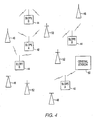
- With reference to Figure 4, a chirp radio communication system may include plural transmitters or tags of a
first type 42, plural transmitters or tags of asecond type 44, plural - receiving stations or base stations of afirst type 46, plural receiving stations or base stations of asecond type 48, and acentral station 50. The receiving stations of the first type and the second type may be co-located in a combinedreceiving station 52. As discussed above, thereceiving stations central station 50. Plwal'central stations may be located in a geographic area to communicate with different types of receiving stations. A difference in type may indicate a difference in chirp signals. - In operation, transmitters of the first type may transmit chirp signals having a first slope and transmitters of the second type may transmit chirp signals having a second slope. The first slope may be different from the second slope in magnitude and/ or polarity (e.g., the sweep of a first chirp signal may be upward over time as in Figure 3, and the sweep of a second chirp signal may be downward in frequency). Preferably, the first slope is of the same magnitude and of opposing polarity as the second slope (i.e., opposing slopes). Preferably, the chirps signals sweep over the entire frequency band of the communication system.
- The receiving stations of the
first type 46 may include correlators for detecting the magnitude and polarity of chirp signal having the first slope. The receiving stations of thesecond type 48 may include correlators for detecting the magnitude and polarity of chirp signals having the second slope. Preferably, the correlators in the receiving stations may discriminate between two types of chirp signals by detecting the chirp signal polarity. - Combined receiving
stations 52 may include two separate correlators for independently detecting the first and second slopes. A receiving station of eithertype central office 50. Alternatively, two central stations may operate separately to process chirp signals transmitted by the two types of transmitters. - Together, the transmitters of the
first type 42, the receiving stations of thefirst type 46, and a central station may be considered to be a first chirp radio communication network and the transmitters of thesecond type 44, the receiving stations of thesecond type 48, and a second or co-located central stations may be considered to be a second chirp radio communication network. Transmitters in one network will not be recognized by the other network. The first and second chirp radio communication networks may include combined receivingstations 52. One of the two networks may be "open" and the other "closed." "Open" may indicate that a chirp radio communication service is provided by subscription and "closed" may indicate that a chirp radio communication service that is provided for a specific customer or set of customers. "Open" and "closed" may also indicate a distinction between national and local services. - A national system may allow roaming and must provide enough "address space" for a nationwide customer base which limits the data space. A local service may require a smaller "address space" and allow higher data transfer.
- The use of two chirp signals provides a simple means for sharing the load in a network by only increasing processor requirement and re-using antenna equipment, communications processor, and possibly a location processor at each receiving station. If one chirp signal increases over time and the other decreases over time, then the two of types of transmitters may coexist in the same network with a modest increase in equipment at each site or multiple networks may be established based on types of transmitters.
- A chirp radio communication system for increasing the number of transmitters, or users, that can be simultaneously accommodated in the communication system and the data capacity of the system without increasing frequency bandwidth. A system may include plural transmitters, receivers, and a central station for establishing chirp radio communications. Each receiver may discriminate between chirp radio transmitter types based on the differing chirp signal characteristics.
- Preferred features of the invention are outlined in the following numbered clauses:
- 1. A method of discriminating between plural types of transmitters transmitting chirp signals of different slopes within a same frequency range in a chirp radio communication system characterized by the steps of:
- (a) receiving a chirp signal;
- (b) detecting the slope of the received chirp signal; and
- (c) determining transmitter type as a function of the detected chirp slope.
- 2. A method as claimed in
clause 1 characterized by the step of asynchronously transmitting chirp signals in a geographic area, in which the transmitter type is determined as a function of the magnitude of the detected chirp slope, or the transmitter type is determined as a function of the polarity of the detected chirp slope, or the transmitter type is determined as a function of the magnitude and polarity of the detected chirp slope. - 3. A method of discriminating between two types of transmitters transmitting chirp signals of opposing slope within the same chirp frequency range of a chirp radio communication system characterized by the steps of:
- (a) receiving a chirp signal;
- (b) detecting the slope of the received chirp signal; and
- (c) determining transmitter type as a function of the detected chirp slope.
- 4. A method as claimed in
clause 3 characterized by the step of asynchronously transmitting chirp signals of opposing slopes. - 5. A chirp radio communication system for transmitting and receiving a first chirp signal of a first predetermined slope, the first predetermined slope continuously increasing in frequency over a predetermined frequency band during a predetermined amount of time, characterized in that the transmitting and receiving a second chirp signal having a different slope from the first predetermined slope over the predetermined frequency band in the same geographic area, so that the data capacity of the system is significantly increased without increasing the first predetermined frequency band.
- 6. A system as claimed in
clause 5 characterized in that the different slope is continuously decreasing in frequency over the predetermined frequency band during the predetermined amount of time. - 7. A system as claimed in clause6 characterized in that the slope of the second chirp signal opposes the first predetermined slope.
- 8. A system as claimed in clause5 characterized in that the first chirp signal and the second chirp signal are being asynchronously transmitted.
- 9. A chirp radio commuriication system operable in a geographic area comprising a first type of receivers and transmitters for receiving and transmitting chirp signals of a first slope and a second type of receivers and transmitters for receiving and transmitting chirp signal of a second slope, and preferably plural types of receivers and transmitters for receiving and transmitting chirp signals, each type of receiver and transmitter receiving and transmitting a chirp signal of a different slope.
- 10. A method of increasing the number of users that can be simultaneously accommodated in a chirp radio communication system characterized by the steps of:
- (a) transmitting and receiving a first chirp signal of a first predetermined slope over a predetermined frequency band; and
- (b) transmitting and receiving a second chirp signal over the predetermined frequency band in the same geographic area, the second chirp signal having a different slope from the first predetermined slope.
- 11. A method as claimed inclause 10characterized by the first chirp signal and the second chirp signal are being transmitted asynchronously, and in which the slope of the second chirp signal opposes the first predetermined slope, or the slope of the second chirp signal having the same polarity and different magnitude from the first predetermined slope.
- 12. A method as claimed in clause10 characterized by the slope of the second chirp signal having a different polarity and different magnitude from the first predetermined slope, or the slope of the second shirp signal having a different polarity and different magnitude from the first predetermined slope.
Claims (4)
- A method of discriminating between plural types of transmitters transmitting chirp signals of different slopes within a same frequency range in a chirp radio communication system characterized by the steps of:(a) receiving a chirp signal;(b) detecting the slope of the received chirp signal; and(c) determining the type of transmitter transmitting the received chirp signal as a function of the detected chirp slope.
- A method as claimed in claim 1 characterized by the steps of asynchronously transmitting chirp signals in a geographic area, and determining the transmitter type as a function of the magnitude of the detected chirp slope, or as a function of the polarity of the detected chirp slope, or as a function of the magnitude and polarity of the detected chirp slope.
- A method as claimed in claim 1 characterized by two types of transmitters transmitting chirp signals of opposing slope within the same chirp frequency range.
- A method as claimed in claim 3 characterized by the step of asynchronously transmitting chirp signals of opposing slopes.
Applications Claiming Priority (2)
| Application Number | Priority Date | Filing Date | Title |
|---|---|---|---|
| US09/527,194 US6850553B1 (en) | 2000-03-17 | 2000-03-17 | Chirp slope multiple access |
| EP01926367A EP1264414A2 (en) | 2000-03-17 | 2001-03-15 | Chirp slope multiple access |
Related Parent Applications (1)
| Application Number | Title | Priority Date | Filing Date |
|---|---|---|---|
| EP01926367A Division EP1264414A2 (en) | 2000-03-17 | 2001-03-15 | Chirp slope multiple access |
Publications (2)
| Publication Number | Publication Date |
|---|---|
| EP1659702A1 true EP1659702A1 (en) | 2006-05-24 |
| EP1659702B1 EP1659702B1 (en) | 2008-12-17 |
Family
ID=24100500
Family Applications (2)
| Application Number | Title | Priority Date | Filing Date |
|---|---|---|---|
| EP01926367A Withdrawn EP1264414A2 (en) | 2000-03-17 | 2001-03-15 | Chirp slope multiple access |
| EP06003240A Expired - Lifetime EP1659702B1 (en) | 2000-03-17 | 2001-03-15 | Chirp slope multiple access |
Family Applications Before (1)
| Application Number | Title | Priority Date | Filing Date |
|---|---|---|---|
| EP01926367A Withdrawn EP1264414A2 (en) | 2000-03-17 | 2001-03-15 | Chirp slope multiple access |
Country Status (9)
| Country | Link |
|---|---|
| US (1) | US6850553B1 (en) |
| EP (2) | EP1264414A2 (en) |
| JP (1) | JP2003528531A (en) |
| CN (1) | CN1248420C (en) |
| AU (1) | AU2001252908A1 (en) |
| CA (1) | CA2400501C (en) |
| DE (1) | DE60137094D1 (en) |
| NO (1) | NO20024283L (en) |
| WO (1) | WO2001071937A2 (en) |
Families Citing this family (9)
| Publication number | Priority date | Publication date | Assignee | Title |
|---|---|---|---|---|
| KR100530365B1 (en) * | 2003-06-19 | 2005-11-22 | 삼성전자주식회사 | UWB wireless transmitter and receiver using UWB linear FM signals having opposite slopes and method thereof |
| US20060265729A1 (en) * | 2005-05-17 | 2006-11-23 | Anglin Richard L Jr | Video communication system |
| WO2007064747A1 (en) * | 2005-11-29 | 2007-06-07 | Pango Networks | Methods and apparatus for active radio frequency identification tags |
| US10725170B2 (en) | 2015-12-17 | 2020-07-28 | Honeywell International Inc. | Frequency modulated continuous wave radio altimeter spectral monitoring |
| US10177868B2 (en) | 2015-12-17 | 2019-01-08 | Honeywell International Inc. | Systems and methods to synchronize wireless devices in the presence of a FMCW radio altimeter |
| US9867180B2 (en) | 2015-12-17 | 2018-01-09 | Honeywell International Inc. | Cognitive allocation of TDMA resources in the presence of a radio altimeter |
| HUE062471T2 (en) | 2017-02-24 | 2023-11-28 | Neosat Gmbh | Orthogonal correlation signals for detection and synchronization at low snr |
| US10299266B2 (en) | 2017-03-20 | 2019-05-21 | Honeywell International Inc. | Delay calculation in wireless systems |
| CN108519167B (en) * | 2018-04-16 | 2019-12-24 | 湖南工学院 | Wireless photonic temperature sensing system and method |
Citations (2)
| Publication number | Priority date | Publication date | Assignee | Title |
|---|---|---|---|---|
| US5105294A (en) * | 1988-06-21 | 1992-04-14 | Canon Kabushiki Kaisha | Digital communicating method and apparatus |
| US5574748A (en) * | 1989-08-23 | 1996-11-12 | Intellon Corporation | Spread spectrum communications system for network |
Family Cites Families (18)
| Publication number | Priority date | Publication date | Assignee | Title |
|---|---|---|---|---|
| US3484693A (en) | 1966-01-03 | 1969-12-16 | Gen Electric | Frequency shifted sliding tone sampled data communication system |
| US4275398A (en) | 1979-04-06 | 1981-06-23 | Del Norte Technology, Inc. | FM Radio ranging system |
| US4438519A (en) | 1981-05-04 | 1984-03-20 | General Electric Company | Methods, and apparatus, for transmitting high-bit-rate digital data in power line communication media having high harmonic noise content |
| JPS61202540A (en) * | 1985-03-05 | 1986-09-08 | Mitsubishi Electric Corp | Chirp modulation/demodulation method |
| US4688251A (en) | 1986-01-21 | 1987-08-18 | The Singer Company | Wave packet communication subsystem for determining the sync pulses and correlating the data pulses of a wave packet |
| JPH01319340A (en) * | 1988-06-21 | 1989-12-25 | Canon Inc | Multiplexing transmission system |
| US5022046A (en) | 1989-04-14 | 1991-06-04 | The United States Of America As Represented By The Secretary Of The Air Force | Narrowband/wideband packet data communication system |
| US5053782A (en) * | 1989-12-13 | 1991-10-01 | Gilat Communication Systems Ltd. | Commercial satellite communications system |
| US5506864A (en) | 1990-12-05 | 1996-04-09 | Interdigital Technology Corporation | CDMA communications and geolocation system and method |
| WO1993004546A1 (en) * | 1991-08-23 | 1993-03-04 | Kabushiki Kaisha Toshiba | Radio information and communication system using multicarrier spread-spectrum transmission system |
| US5592180A (en) | 1992-08-20 | 1997-01-07 | Nexus1994 Limited | Direction finding and mobile location system for trunked mobile radio systems |
| US5515396A (en) | 1994-02-25 | 1996-05-07 | Motorola, Inc. | Method and apparatus for selecting a spreading code in a spectrum spread communication system |
| JP2798129B2 (en) * | 1996-08-26 | 1998-09-17 | 日本電気株式会社 | Transmitter and receiver for chirp spread spectrum signal multiplexer |
| US5859613A (en) * | 1996-08-30 | 1999-01-12 | Harris Corporation | System and method for geolocating plural remote transmitters |
| US5982808A (en) * | 1996-08-30 | 1999-11-09 | Harris Corporation | System and method for communicating with plural remote transmitter |
| JP2755296B2 (en) * | 1996-10-18 | 1998-05-20 | 日本電気株式会社 | Spread spectrum signal multiplexer |
| DE19646747C1 (en) * | 1996-11-01 | 1998-08-13 | Nanotron Ges Fuer Mikrotechnik | Method for the wireless transmission of a message imprinted on a signal |
| KR20010052576A (en) * | 1998-06-04 | 2001-06-25 | 스콧 티. 마이쿠엔 | A system and method for communicating with plural remote transmitters |
-
2000
- 2000-03-17 US US09/527,194 patent/US6850553B1/en not_active Expired - Fee Related
-
2001
- 2001-03-15 CN CNB018064116A patent/CN1248420C/en not_active Expired - Fee Related
- 2001-03-15 DE DE60137094T patent/DE60137094D1/en not_active Expired - Lifetime
- 2001-03-15 AU AU2001252908A patent/AU2001252908A1/en not_active Abandoned
- 2001-03-15 JP JP2001569992A patent/JP2003528531A/en active Pending
- 2001-03-15 EP EP01926367A patent/EP1264414A2/en not_active Withdrawn
- 2001-03-15 WO PCT/US2001/008370 patent/WO2001071937A2/en not_active Ceased
- 2001-03-15 EP EP06003240A patent/EP1659702B1/en not_active Expired - Lifetime
- 2001-03-15 CA CA002400501A patent/CA2400501C/en not_active Expired - Lifetime
-
2002
- 2002-09-09 NO NO20024283A patent/NO20024283L/en not_active Application Discontinuation
Patent Citations (2)
| Publication number | Priority date | Publication date | Assignee | Title |
|---|---|---|---|---|
| US5105294A (en) * | 1988-06-21 | 1992-04-14 | Canon Kabushiki Kaisha | Digital communicating method and apparatus |
| US5574748A (en) * | 1989-08-23 | 1996-11-12 | Intellon Corporation | Spread spectrum communications system for network |
Also Published As
| Publication number | Publication date |
|---|---|
| NO20024283L (en) | 2002-11-14 |
| WO2001071937A2 (en) | 2001-09-27 |
| CA2400501C (en) | 2008-10-14 |
| EP1264414A2 (en) | 2002-12-11 |
| DE60137094D1 (en) | 2009-01-29 |
| WO2001071937A3 (en) | 2002-05-23 |
| US6850553B1 (en) | 2005-02-01 |
| EP1659702B1 (en) | 2008-12-17 |
| CA2400501A1 (en) | 2001-09-27 |
| AU2001252908A1 (en) | 2001-10-03 |
| CN1248420C (en) | 2006-03-29 |
| CN1418409A (en) | 2003-05-14 |
| NO20024283D0 (en) | 2002-09-09 |
| JP2003528531A (en) | 2003-09-24 |
Similar Documents
| Publication | Publication Date | Title |
|---|---|---|
| US5982808A (en) | System and method for communicating with plural remote transmitter | |
| US5859613A (en) | System and method for geolocating plural remote transmitters | |
| US4812852A (en) | Locating system and method | |
| CA1298903C (en) | Vehicle location system | |
| US4916455A (en) | Locating system and method | |
| AU2964595A (en) | Apparatus and method for locating cellular telephones and similar transmitters | |
| EP2092364A1 (en) | Location system for wireless local area network (wlan) using rssi and time difference of arrival (tdoa) processing | |
| AU2002321129A1 (en) | Method of determining the position of a target using transmitters of opportunity | |
| CA2400501C (en) | Chirp slope multiple access | |
| WO2001009634A2 (en) | Portable gps receiver for a personal safety system | |
| AU7244798A (en) | A cellular positioning system that compensates for received signal delays in positioning radio receivers | |
| EP1086446B1 (en) | A system and method for communicating with plural remote transmitters | |
| WO1999063501A1 (en) | A system and method for communicating and/or geolocating plural remote transmitters using a time invariant matched filter | |
| CA2605880A1 (en) | Chirp slope multiple access | |
| EP1086384B1 (en) | A system and method for geolocating plural remote transmitters | |
| EP0717852A1 (en) | Apparatus and method for locating cellular telephones and similar transmitters | |
| JP4849719B2 (en) | Information distribution system | |
| KR19990048117A (en) | Emergency signal system using wireless signal |
Legal Events
| Date | Code | Title | Description |
|---|---|---|---|
| PUAI | Public reference made under article 153(3) epc to a published international application that has entered the european phase |
Free format text: ORIGINAL CODE: 0009012 |
|
| AC | Divisional application: reference to earlier application |
Ref document number: 1264414 Country of ref document: EP Kind code of ref document: P |
|
| AK | Designated contracting states |
Kind code of ref document: A1 Designated state(s): AT BE CH CY DE DK ES FI FR GB GR IE IT LI LU MC NL PT SE TR |
|
| AX | Request for extension of the european patent |
Extension state: AL LT LV MK RO SI |
|
| 17P | Request for examination filed |
Effective date: 20060509 |
|
| 17Q | First examination report despatched |
Effective date: 20060706 |
|
| AKX | Designation fees paid |
Designated state(s): DE FR GB IT |
|
| GRAP | Despatch of communication of intention to grant a patent |
Free format text: ORIGINAL CODE: EPIDOSNIGR1 |
|
| GRAS | Grant fee paid |
Free format text: ORIGINAL CODE: EPIDOSNIGR3 |
|
| GRAA | (expected) grant |
Free format text: ORIGINAL CODE: 0009210 |
|
| AC | Divisional application: reference to earlier application |
Ref document number: 1264414 Country of ref document: EP Kind code of ref document: P |
|
| AK | Designated contracting states |
Kind code of ref document: B1 Designated state(s): DE FR GB IT |
|
| REG | Reference to a national code |
Ref country code: GB Ref legal event code: FG4D |
|
| REF | Corresponds to: |
Ref document number: 60137094 Country of ref document: DE Date of ref document: 20090129 Kind code of ref document: P |
|
| PLBE | No opposition filed within time limit |
Free format text: ORIGINAL CODE: 0009261 |
|
| STAA | Information on the status of an ep patent application or granted ep patent |
Free format text: STATUS: NO OPPOSITION FILED WITHIN TIME LIMIT |
|
| 26N | No opposition filed |
Effective date: 20090918 |
|
| REG | Reference to a national code |
Ref country code: FR Ref legal event code: PLFP Year of fee payment: 16 |
|
| REG | Reference to a national code |
Ref country code: FR Ref legal event code: PLFP Year of fee payment: 17 |
|
| REG | Reference to a national code |
Ref country code: FR Ref legal event code: PLFP Year of fee payment: 18 |
|
| PGFP | Annual fee paid to national office [announced via postgrant information from national office to epo] |
Ref country code: FR Payment date: 20190325 Year of fee payment: 19 Ref country code: IT Payment date: 20190322 Year of fee payment: 19 Ref country code: DE Payment date: 20190327 Year of fee payment: 19 |
|
| PGFP | Annual fee paid to national office [announced via postgrant information from national office to epo] |
Ref country code: GB Payment date: 20190404 Year of fee payment: 19 |
|
| REG | Reference to a national code |
Ref country code: DE Ref legal event code: R119 Ref document number: 60137094 Country of ref document: DE |
|
| PG25 | Lapsed in a contracting state [announced via postgrant information from national office to epo] |
Ref country code: DE Free format text: LAPSE BECAUSE OF NON-PAYMENT OF DUE FEES Effective date: 20201001 Ref country code: FR Free format text: LAPSE BECAUSE OF NON-PAYMENT OF DUE FEES Effective date: 20200331 |
|
| GBPC | Gb: european patent ceased through non-payment of renewal fee |
Effective date: 20200315 |
|
| PG25 | Lapsed in a contracting state [announced via postgrant information from national office to epo] |
Ref country code: GB Free format text: LAPSE BECAUSE OF NON-PAYMENT OF DUE FEES Effective date: 20200315 |
|
| PG25 | Lapsed in a contracting state [announced via postgrant information from national office to epo] |
Ref country code: IT Free format text: LAPSE BECAUSE OF NON-PAYMENT OF DUE FEES Effective date: 20200315 |