EP1659275A2 - Outboard engine system - Google Patents
Outboard engine system Download PDFInfo
- Publication number
- EP1659275A2 EP1659275A2 EP05257179A EP05257179A EP1659275A2 EP 1659275 A2 EP1659275 A2 EP 1659275A2 EP 05257179 A EP05257179 A EP 05257179A EP 05257179 A EP05257179 A EP 05257179A EP 1659275 A2 EP1659275 A2 EP 1659275A2
- Authority
- EP
- European Patent Office
- Prior art keywords
- trim
- thrust receiver
- lubricant
- trim rod
- thrust
- Prior art date
- Legal status (The legal status is an assumption and is not a legal conclusion. Google has not performed a legal analysis and makes no representation as to the accuracy of the status listed.)
- Granted
Links
- 239000000314 lubricant Substances 0.000 claims description 34
- 238000005096 rolling process Methods 0.000 claims description 12
- 230000000717 retained effect Effects 0.000 claims description 2
- 230000002159 abnormal effect Effects 0.000 abstract description 15
- 230000008602 contraction Effects 0.000 abstract description 5
- 239000004519 grease Substances 0.000 description 9
- 210000002445 nipple Anatomy 0.000 description 3
- 238000012423 maintenance Methods 0.000 description 2
- 230000001174 ascending effect Effects 0.000 description 1
- 238000004891 communication Methods 0.000 description 1
- 230000003247 decreasing effect Effects 0.000 description 1
- 230000000994 depressogenic effect Effects 0.000 description 1
- 238000013461 design Methods 0.000 description 1
- 230000001050 lubricating effect Effects 0.000 description 1
- 238000004519 manufacturing process Methods 0.000 description 1
- 238000000034 method Methods 0.000 description 1
- 238000012986 modification Methods 0.000 description 1
- 230000004048 modification Effects 0.000 description 1
- 230000002093 peripheral effect Effects 0.000 description 1
Images






Classifications
-
- B—PERFORMING OPERATIONS; TRANSPORTING
- B63—SHIPS OR OTHER WATERBORNE VESSELS; RELATED EQUIPMENT
- B63H—MARINE PROPULSION OR STEERING
- B63H20/00—Outboard propulsion units, e.g. outboard motors or Z-drives; Arrangements thereof on vessels
- B63H20/08—Means enabling movement of the position of the propulsion element, e.g. for trim, tilt or steering; Control of trim or tilt
- B63H20/10—Means enabling trim or tilt, or lifting of the propulsion element when an obstruction is hit; Control of trim or tilt
- B63H20/106—Means enabling lifting of the propulsion element in a substantially vertical, linearly sliding movement
-
- F—MECHANICAL ENGINEERING; LIGHTING; HEATING; WEAPONS; BLASTING
- F02—COMBUSTION ENGINES; HOT-GAS OR COMBUSTION-PRODUCT ENGINE PLANTS
- F02B—INTERNAL-COMBUSTION PISTON ENGINES; COMBUSTION ENGINES IN GENERAL
- F02B61/00—Adaptations of engines for driving vehicles or for driving propellers; Combinations of engines with gearing
- F02B61/04—Adaptations of engines for driving vehicles or for driving propellers; Combinations of engines with gearing for driving propellers
- F02B61/045—Adaptations of engines for driving vehicles or for driving propellers; Combinations of engines with gearing for driving propellers for marine engines
Definitions
- the present invention relates to an outboard engine system in which a trim angle of a system body can be adjusted with respect to a hull by a trim device and a thrust receiver which are mounted on one and the other of the system body and a mounting device, respectively.
- a tip end face of an expandable and contractable trim rod of a trim cylinder mounted on a stern bracket is in abutment against a rotatable ball of a thrust receiver mounted on a swivel case; and generation of an abnormal sound due to a twisting is prevented by rolling of the ball on the tip end face of the trim rod, when the trim rod is expanded or contracted to adjust a trim angle of a system body.
- a ball rotatably mounted at a tip end of a trim rod of a trim cylinder is in abutment against a pressure-receiving surface of a thrust receiver; and generation of an abnormal sound due to a twisting is prevented by rolling of the ball on the pressure-receiving surface of the thrust receiver, when the trim rod is expanded or contracted to adjust a trim angle of a system body.
- an outboard engine system comprising: a system body having a propeller shaft; a mounting device for mounting the system body to a hull for tilting movement; a trim device having an expandable and contractable trim rod mounted on one of the system body and the mounting device; and a thrust receiver mounted on the other of the system body and the mounting device to support a thrust force of the system body transmitted through the trim rod of the trim device, wherein the thrust receiver includes: a shaft portion supported for rotation about an axis generally parallel to an axis of the trim rod; and a pressure-receiving port ion provided at one end of the shaft portion to abut against a tip end of the trim rod; and wherein an abutment point between the tip end of the trim rod and the pressure-receiving portion of the thrust receiver is displaced from the axis of the shaft portion in a lateral direction of the system body.
- the thrust receiver abuts against the expandable and contractable trim rod to adjust the trim angle of the system body, and includes the shaft portion rotatable about the axis generally parallel to the axis of the trim rod, and the pressure-receiving portion provided on the shaft portion to abut against the tip end of the trim rod; and the abutment point between the trim rod and the pressure-receiving portion is displaced from the axis of the shaft portion in a lateral direction of the system body. Therefore, a twisting generated at the abutment point can be minimized to suppress the generation of an abnormal sound by the rotation of the pressure-receiving portion of the thrust receiver about the axis accompanying the expansion or contraction of the trim rod.
- the structure can be simplified to contribute to a reduction in cost, and further it is not necessary to roll a ball at the tip end of the trim rod, and hence the diameter of the trim rod can be reduced.
- the shaft portion of the thrust receiver also serves as a mounting portion.
- the shaft portion of the thrust receiver also serves as the mounting portion, and hence the thrust receiver can be mounted utilizing the shaft portion without provision of a special mounting portion, leading to a simplified structure.
- the system further comprises a lubricant-supplying means for supplying lubricant to a surface of the pressure-receiving portion of the thrust receiver.
- the lubricant is supplied from the lubricant supplying means to the surface of the pressure-receiving portion of the thrust receiver, and hence the abutment point between the pressure-receiving portion and the trim rod can be lubricated to further effectively prevent an abnormal sound generated during changing of the trim angle.
- the thrust receiver is mounted for movement relative to at least one of the trim rod and the system body, and the system further includes a lubricant-retaining portion for supplying lubricant to portions moved relative to each other.
- the thrust receiver is moved relative to at least one of the trim rod and the system body.
- a sufficient amount of lubricant can be continuously supplied to the relatively-moved portions to prevent the generation of an abnormal sound over a long period, because the lubricant-retaining portion for supplying the lubricant to the relatively-moved portions.
- the thrust receiver has, on its surface abutting against the trim rod, a contact portion and a non-contact portion with the trim rod so that lubricant is supplied from the lubricant-retaining portion through the non-contact portion to the contact portion.
- the thrust receiver has the contact portion and the non-contact portion on its surface abutting against the trim rod, and the lubricant is supplied from the lubricant-retaining portion through the non-contact portion to the contact portion. Therefore, it is possible to prevent the trim rod from abutting against the non-contact portion which has grooves or steps for guiding lubricant and obstructing the smooth abutment.
- the thrust receiver comprises a rolling member rotatably retained on a holding member so that lubricant is supplied from the lubricant-retaining portion to a non-contact portion between the rolling member and the holding member.
- the thrust receiver rotatably retains the rollingmember on the retainingmember, and the lubricant is supplied from the lubricant-retaining portion to the non-contact portion between the rolling member and the retaining member. Therefore, the non-contact portion between the rolling member and the retaining member can be effectively lubricated over a long period by the lubricant accumulated in the non-contact portion.
- a sliding portion is formed at a portion of the thrust receiver, and the sliding portion has a lubricant charging bore for charging lubricant from outside to the sliding portion.
- the thrust receiver is slid on the sliding portion.
- the lubricant can be easily supplied to the sliding portion without disassembling the thrust receiver thereby preventing the generation of an abnormal sound, because the sliding portion has the lubricant charging bore for charging the lubricant from outside to the sliding portion.
- a stern bracket 23 in an embodiment corresponds to the mounting device of the present invention; a trim cylinder 30 in the embodiment corresponds to the trim device of the present invention; a propelling unit U in the embodiment corresponds to the system body of the present invention; a transom in the embodiment corresponds to the hull of the present invention; and an oil groove g3 in the embodiment corresponds to the lubricant supplying means of the present invention.
- a trim cylinder 30 in an embodiment corresponds to the trim device of the present invention; an oil reservoir 31c, oil passages 32c, 32d, 44b, 44c and oil grooves g1 and g2 in the embodiment correspond to the lubricant-retaining portion of the present invention; a grease charging bore 31d in the embodiment corresponds to the lubricant charging bore of the present invention; grease 39 in the embodiment corresponds to the lubricant of the present invention; a ball holder 44 in the embodiment corresponds to the retaining member of the present invention; a ball 45 in the embodiment corresponds to the rolling member of the present invention; a space 46 and an oil groove g3 in the embodiment correspond to the non-contact portion of the present invention; a propelling unit U in the embodiment corresponds to the system body of the present invention; and a transom T in the embodiment corresponds to the hull of the present invention.
- Amounting device of an outboard engine system O is generally comprises a stern bracket 23 and a swivel case 22, but in this specification, it is defined that the mounting device comprises a stern bracket 23, and a swivel case 22 is a portion of a propelling unit U.
- FIG.1 to 12 show a first embodiment of the present invention, wherein
- a propelling unit U constituting a body portion of an outboard engine system O includes a support case assembly 11 and a gear case 12 coupled to a lower portion of the support case assembly 11.
- a water-cooled multi-cylinder 4-stroke engine E is mounted at an upper portion of the support case assembly 11 with its crankshaft 13 disposed vertically.
- An engine cover 14 is openably and closably mounted at an upper end of the support case assembly 11 to cover the engine E.
- the support case assembly 11 is a general term including a mount case which supports a main block of the engine E, an extension case coupled to a lower portion of the mount case, and an undercover which covers peripheries of the mount case and the extension case and receives the engine cover 14 to cover the engine E.
- a drive shaft 15 disposed vertically within the support case assembly 11 is connected to a crankshaft 13 of the engine E.
- a propeller shaft 17 mounting a propeller 16 at its rear end is supported within the gear case 12.
- a forward and backward movement switchover mechanism 18 connecting the driver shaft 15 to the propeller shaft 17 is housed in the gear case 12. Therefore, a driving force transmitted from the crankshaft 13 to the drive shaft 15 during operation of the engine E is transmitted through the forward and backward movement switchover mechanism 18 to the propeller shaft 17, and the direction of rotation of the propeller shaft 17 is controlled by the forward and backward movement switchover mechanism 18.
- a vertically-extending swivel shaft 21 is secured at its opposite ends to an upper arm 19 supporting an upper portion of the support case assembly 11 and a lower arm 20 supporting a lower portion of the support case assembly 11.
- a swivel case 22 rotatably supporting the swivel shaft 21 is connected through a horizontal tilting shaft 24 to upper portions of a pair of left and right stern brackets 23, 23 which are disposed to sandwich the swivel case 22 from the left and right and clamped to a transom T of a hull.
- the propellingunit Uof the outboard engine system O can vertically swing about the tilting shaft 24, and the outboard engine system O is divided into the stern brackets 23, 23 fixed to the hull, and the swivel case 22 and the propelling unit U which can swing with respect to the hull.
- the swivel case 22 includes a cylindrical case section 25 which directly supports the swivel shaft 21, and an arm section 26 extending forwards (toward the hull) from an upper portion of the case section 25 and supported on the tilting shaft 24.
- a laterally-extending upper pivot 27 is supported at its opposite ends within the arm section 26.
- a tilting cylinder 29 is pivotally supported at its lower end on a lower pivot 28 laid laterally at lower portions of the pair of left and right stern brackets 23, 23, and a cylinder rod 29a protruding from an upper end of the tilting cylinder 29 is pivotally supported on the upper pivot 27.
- a pair of trim cylinders 30, 30 are integrally formed on laterally opposite sides of the tilting cylinder 29, and trim rods 30a, 30a protrude from upper ends of the trim cylinders 30, 30 for expansion and contraction.
- a pair of thrust receiver-supporting portions 31, 31 overhang from laterally opposite sides of the case section 25 of the swivel case 22, and thrust receivers 32 having the same structure are mounted on the thrust receiver-supporting portions 31, 31, respectively.
- the thrust receiver 32 is integrally provided with a bar-shaped shaft portion 32a and a disk-shaped pressure receiving portion 32b.
- the shaft portion 32a is rotatably supported on a first bush 33 and a second bush 34 which are press-fitted into a support bore 31a formed so as to pass through the thrust receiver-supporting portion 31.
- the pressure receiving portion 32b is integrally formed at an end of the shaft portion 32a on the second bush 34 side, and a nut 38 is threadedly fitted over a tip end of the shaft portion 32a protruding from the first bush 33 with three washers 35, 36 and 37 interposed therebetween, whereby the thrust receiver 32 is fixed in a slip-off preventing manner.
- the pressure receiving portion 32b has a surface depressed in a partially spherical shape, and a rounded tip end of the trim rod 30a is placed into abutment against the spherical surface.
- An axis L2 of the shaft portion 32a of the thrust receiver 32 is generally parallel to an axis L1 of the trim rod 30a of the trim cylinder 30 as viewed from sideways (see Fig. 4), but the axis L2 of the shaft portion 32a of the thrust receiver 32 is displaced laterally by a distance ⁇ from the axis L1 of the trim rod 30a of the trim cylinder 30, as viewed in plane. Therefore, an abutment point P between the trim rod 30a and the pressure receiving portion 32b of the thrust receiver 32 is displaced laterally by a distance ⁇ from the axis L2 of the shaft portion 32a of the thrust receiver 32 (see Fig.6).
- the second bush 34 includes a cylindrical portion 34a and a flange portion 34b.
- Six oil grooves g1 are formed in the cylindrical portion 34a to extend in a direction of the axis L2.
- Six blind oil grooves g2 are formed radially in an outer surface of the flange portion 34b and connected to the six oil grooves g1, respectively.
- An oil passage 31b formed in the thrust receiver-supporting portion 31 communicates with an annular oil reservoir 31c which is formed between the first and second bushes 33 and 34 and which communicates with the oil grooves g1 in the second bush 34.
- Grease 39 is charged from a nipple 40 provided in a grease charging bore 31d opening into an outer surface of the thrust receiver-supporting portion 31, through the oil passage 31b and the oil reservoir 31c, into the oil grooves g1 and g2.
- a thrust force generated by the propeller 16 during operation of the outboard engine system O causes the propelling unit U to swing in a counterclockwise direction in Fig.1 about the tilting shaft 24, but this thrust force is transmitted from the pair of thrust receivers 32, 32 mounted on the swivel case 22 through the trim cylinders 30, 30, the tilting cylinder 29 and the stern brackets 23, 23 to the transom T, and an angle of the propelling unit U with respect of the hull is maintained at a predetermined trim angle.
- the trim cylinders 30, 30 are driven for expansion to cause the trim rods 30a, 30a to protrude, as shown in Fig.12, the thrust receiver-supporting portions 31, 31 of the swivel case 22 are urged backwards, whereby the propelling unit U is slightly swung about the tilting shaft 24, thereby finely adjusting the thrust shaft of the propeller 16 into a backward ascending inclination.
- the trim cylinders 30, 30 are driven for contraction to cause the trim rods 30a, 30a to retract, the thrust shaft of the propeller 16 is finely adjusted into a backward descending inclination.
- the locus of movement of the thrust receiver 32 draws an arc L3 of a circle about the tilting shaft 24 as shown in Fig.2, while the locus of movement of the trim rod 30a of the trim cylinder 30 is generally in line with the axis L1.
- the locus of movement of the thrust receiver 32 and the locus of movement of the trim rod 30a are not in line with each other, as described above, there is a possibility that a twisting is generated at the abutment point P (see Fig. 6) between the tip end of the trim rod 30a and the pressure receiving portion 32b of the thrust receiver 32 to generate an abnormal sound.
- the pressure receiving portion 32b of the thrust receiver 32 can be rotated freely about the axis L2 of the shaft portion 32a, and the abutment point P is displaced laterally by the distance ⁇ from the axis L2 of the shaft portion 32a of the thrust receiver 32 (see Fig.6). Therefore, the twisting can be effectively suppressed to reduce the generation of the abnormal sound by the free rotation of the thrust receiver 32 accompanying the expansion or contraction of the trim rod 30a.
- the thrust receiver 32 is supported on the thrust receiver-supporting portion 31 by utilizing the shaft portion 32a which serves as the axis for rotation of the thrust receiver 32, thus contributing to simplification of the structure.
- the tip end of the trim rod 30a is moved generally linearly on the axis L1, while the pressure receiving portion 32b of the thrust receiver 32 is rotated about the axis L2. Therefore, a slipping is generated between the trim rod 30a and the pressure receiving portion 32b, but this slipping cannot generate an abnormal sound, because it is extremely slight.
- the generation of the twisting can be suppressed to reduce the abnormal sound by only supporting the thrust receiver 32 for rotation without disposition of a ball on either the trim rod 30a or the thrust receiver 32 for bringing both of them into rolling contact with each other.
- This can simplify the structure to contribute to a reduction in cost.
- it is not necessary to roll a ball on a tip end face of the trim rod 30a, and hence the diameter of the trim rod 30a can be decreased.
- the thrust force generated by the propelling unit U is transmitted from the thrust receiver 32 to the trim rod 30a, the thrust force acting on the pressure receiving portion 32b of the thrust receiver 32 is supported on the thrust receiver-supporting portion 31 of the swivel case 32 through the flange portion 34b of the second bush 34.
- the lubricant filled in the oil reservoir 31c is supplied through the oil grooves g1 in the shaft portion 34a of the second bush 34 into the oil grooves g2 in the flange portion 34b, and hence the thrust receiver 32 can be rotated even under a large thrust force, thereby effectively suppressing the generation of an abnormal sound.
- the lubricant supplied to the oil grooves g1 lubricates sliding surfaces between the shaft portion 32a of the thrust receiver 32 and the cylindrical portion 34a of the second bush 34.
- the bush section is bisected into the first and second bushes 33 and 34, and the oil reservoir 31c is formed between the first and second bushes 33 and 34. Therefore, it is possible not only to easily form the oil reservoir 31c, but also to reliably supply the lubricant to both the first and second bushes 33 and 34 over a long period by continuously supplying the lubricant from the oil reservoir 31c to the sliding surfaces. Moreover, the oil reservoir 31c communicates with the grease charging bore 31d in the surface of the thrust receiver-supporting portion 31 through the oil passage 31b, and hence the supply of the lubricant can be carried out without separating the thrust receiver 32 from the thrust receiver-supporting portion 31, leading to an enhanced maintenance property.
- the shaft portion 32a of the thrust receiver 32 is fixed in a slip-off preventing manner by the nut 38, but in the second embodiment, a shaft portion 32a of a thrust receiver 32 is fixed in the slip-off preventing manner by a cisclip 41 in place of the nut 38. According to the second embodiment, the mounting and removing of the thrust receiver 32 are further facilitated, leading to an enhanced maintenance property.
- the abutment point P between he pressure receiving portion 32b of the thrust receiver 32 and the trim rod 30a is not lubricated, but in the third embodiment, the abutment point P is lubricated by lubricant from an oil reservoir 31c. More specifically, oil passages 32c and 32d are formed within a shaft portion 32a of a thrust receiver 32 to provide a communication between surfaces of the oil reservoir 31a and the pressure receiving portion 32b, and a plurality of (two in the embodiment) oil grooves g3 are formed in the surface of the pressure receiving portion 32b to extend radially from an outlet of the oil passage 32d.
- the abutment point P between the pressure receiving portion 32b of the thrust receiver 32 and the trim rod 30a can be lubricated to further reduce an abnormal sound during adjustment of the trim angle.
- the oil grooves g3 as non-contact portions are out of a range (a contact portion t ) of a locus of the abutment point P of the trim rod 30a, and lubricant can be supplied to the contact point P existing in,the contact portion t , while preventing the trim rod 30a from contacting the oil grooves g3 and obstructing the smooth movement.
- the oil grooves g3 may be provided in all radial directions in correspondence to the rotation of the thrust receiver 32.
- the fourth embodiment is different from the first embodiment (see Fig.6) with respect to the structure of a thrust receiver 32.
- the thrust receiver 32 in the fourth embodiment includes a ball holder 44 which is fitted into a support bore 31c in a thrust receiver-supporting portion 31 and fixed by a washer 42 and a nut 43.
- a ball-retaining portion 44a is formed at a tip end of the ball holder 44 protruding from the thrust receiver-supporting portion 31, and a ball 45 is rotatably supported within the ball-retaining portion 44a to abut against a flat tip end face of a trim rod 30a for rolling.
- An oil passage 31b and an oil reservoir 31c are formed in the thrust receiver-supporting portion 31 to lead to a nipple 40.
- the oil reservoir 31c communicates with a space 46 formed between the ball-retaining portion 44a and the ball 45 through oil passages 44b and 44c formed within the ball holder 44.
- sliding portions between the ball-retaining portion 44a and the ball 45 can be lubricated over a long period by the grease 39 stored in the oil passage 31b, the oil reservoir 31c, the oil passages 44b and 44c and the space 46, and moreover the grease 39 can be easily supplied from the outside using the nipple 40.
- the trim cylinders 30, 30 are mounted on the stern brackets 23, 23, and the thrust receivers 32, 32 are mounted on the propelling unit U, but the positional relationship between them can be reversed, i.e., the trim cylinders may be mounted on the propelling unit U, and the thrust receivers 32, 32 may be mounted on the stern brackets 23, 23.
- the lubricant for lubricating the abutment point P between the pressure-receiving portion 32b of the thrust receiver 32 and the trim rod 30a is supplied from the side of the thrust receiver 32, but may be supplied from the side of the trim rod 30a.
Landscapes
- Engineering & Computer Science (AREA)
- Ocean & Marine Engineering (AREA)
- Chemical & Material Sciences (AREA)
- Combustion & Propulsion (AREA)
- Mechanical Engineering (AREA)
- General Engineering & Computer Science (AREA)
- Shafts, Cranks, Connecting Bars, And Related Bearings (AREA)
- Sliding-Contact Bearings (AREA)
- Pistons, Piston Rings, And Cylinders (AREA)
Abstract
Description
- The present invention relates to an outboard engine system in which a trim angle of a system body can be adjusted with respect to a hull by a trim device and a thrust receiver which are mounted on one and the other of the system body and a mounting device, respectively.
- Such an outboard engine system is known from Japanese Patent Application Laid-open No. 8-91298 and Japanese Utility Model Application Laid-open Nos. 62-100297 and 61-132199.
- In the outboard engine system described in each of Japanese Patent Application Laid-open No.8-91298and Japanese Utility Model Application Laid-open No. 62-100297, a tip end face of an expandable and contractable trim rod of a trim cylinder mounted on a stern bracket is in abutment against a rotatable ball of a thrust receiver mounted on a swivel case; and generation of an abnormal sound due to a twisting is prevented by rolling of the ball on the tip end face of the trim rod, when the trim rod is expanded or contracted to adjust a trim angle of a system body.
- In the outboard engine system described in Japanese Utility Model Application Laid-open No. 61-132199, a ball rotatably mounted at a tip end of a trim rod of a trim cylinder is in abutment against a pressure-receiving surface of a thrust receiver; and generation of an abnormal sound due to a twisting is prevented by rolling of the ball on the pressure-receiving surface of the thrust receiver, when the trim rod is expanded or contracted to adjust a trim angle of a system body.
- However, all the systems in the above-described documents have a problem of a high manufacturing cost, because they need the ball for bringing the trim rod and the thrust receiver into rolling contact with each other in order to adjust the trim angle.
- Accordingly, it is an object of the present invention to provide a simple structure for reducing an abnormal sound generated when adjusting the trim angle of a body of an outboard engine system by a trim device and a thrust receiver.
- In order to achieve the above object, according to a first feature of the present invention, there is provided an outboard engine system comprising: a system body having a propeller shaft; a mounting device for mounting the system body to a hull for tilting movement; a trim device having an expandable and contractable trim rod mounted on one of the system body and the mounting device; and a thrust receiver mounted on the other of the system body and the mounting device to support a thrust force of the system body transmitted through the trim rod of the trim device, wherein the thrust receiver includes: a shaft portion supported for rotation about an axis generally parallel to an axis of the trim rod; and a pressure-receiving port ion provided at one end of the shaft portion to abut against a tip end of the trim rod; and wherein an abutment point between the tip end of the trim rod and the pressure-receiving portion of the thrust receiver is displaced from the axis of the shaft portion in a lateral direction of the system body.
- With the above arrangement, the thrust receiver abuts against the expandable and contractable trim rod to adjust the trim angle of the system body, and includes the shaft portion rotatable about the axis generally parallel to the axis of the trim rod, and the pressure-receiving portion provided on the shaft portion to abut against the tip end of the trim rod; and the abutment point between the trim rod and the pressure-receiving portion is displaced from the axis of the shaft portion in a lateral direction of the system body. Therefore, a twisting generated at the abutment point can be minimized to suppress the generation of an abnormal sound by the rotation of the pressure-receiving portion of the thrust receiver about the axis accompanying the expansion or contraction of the trim rod. Moreover, as compared with a conventional system in which a ball is disposed at the abutment point, the structure can be simplified to contribute to a reduction in cost, and further it is not necessary to roll a ball at the tip end of the trim rod, and hence the diameter of the trim rod can be reduced.
- According to a second feature of the present invention, in addition to the first feature, the shaft portion of the thrust receiver also serves as a mounting portion.
- With the above arrangement, the shaft portion of the thrust receiver also serves as the mounting portion, and hence the thrust receiver can be mounted utilizing the shaft portion without provision of a special mounting portion, leading to a simplified structure.
- According to a third feature of the present invention, in addition to the first or second feature, the system further comprises a lubricant-supplying means for supplying lubricant to a surface of the pressure-receiving portion of the thrust receiver.
- With the above arrangement, the lubricant is supplied from the lubricant supplying means to the surface of the pressure-receiving portion of the thrust receiver, and hence the abutment point between the pressure-receiving portion and the trim rod can be lubricated to further effectively prevent an abnormal sound generated during changing of the trim angle.
- According to a fourth feature of the present invention, in addition to the first feature, the thrust receiver is mounted for movement relative to at least one of the trim rod and the system body, and the system further includes a lubricant-retaining portion for supplying lubricant to portions moved relative to each other.
- With the above arrangement, when the expandable and contractable trim rod of the trim device is put into abutment against the thrust receiver in order to adjust the trim angle of the system body, the thrust receiver is moved relative to at least one of the trim rod and the system body. However, a sufficient amount of lubricant can be continuously supplied to the relatively-moved portions to prevent the generation of an abnormal sound over a long period, because the lubricant-retaining portion for supplying the lubricant to the relatively-moved portions.
- According to a fifth feature of the present invention, in addition to the fourth feature, the thrust receiver has, on its surface abutting against the trim rod, a contact portion and a non-contact portion with the trim rod so that lubricant is supplied from the lubricant-retaining portion through the non-contact portion to the contact portion.
- With the above arrangement, the thrust receiver has the contact portion and the non-contact portion on its surface abutting against the trim rod, and the lubricant is supplied from the lubricant-retaining portion through the non-contact portion to the contact portion. Therefore, it is possible to prevent the trim rod from abutting against the non-contact portion which has grooves or steps for guiding lubricant and obstructing the smooth abutment.
- According to a sixth feature of the present invention, in addition to the fourth or fifth feature, the thrust receiver comprises a rolling member rotatably retained on a holding member so that lubricant is supplied from the lubricant-retaining portion to a non-contact portion between the rolling member and the holding member.
- With the above arrangement, the thrust receiver rotatably retains the rollingmember on the retainingmember, and the lubricant is supplied from the lubricant-retaining portion to the non-contact portion between the rolling member and the retaining member. Therefore, the non-contact portion between the rolling member and the retaining member can be effectively lubricated over a long period by the lubricant accumulated in the non-contact portion.
- According to a seventh feature of the present invention, in addition to the first feature, a sliding portion is formed at a portion of the thrust receiver, and the sliding portion has a lubricant charging bore for charging lubricant from outside to the sliding portion.
- With the above arrangement, when the expandable and contractable trim rod of the trim device is put into abutment against the thrust receiver in order to adjust the trim angle of the system body, the thrust receiver is slid on the sliding portion. However, the lubricant can be easily supplied to the sliding portion without disassembling the thrust receiver thereby preventing the generation of an abnormal sound, because the sliding portion has the lubricant charging bore for charging the lubricant from outside to the sliding portion.
- In the first to third features, a
stern bracket 23 in an embodiment corresponds to the mounting device of the present invention; atrim cylinder 30 in the embodiment corresponds to the trim device of the present invention; a propelling unit U in the embodiment corresponds to the system body of the present invention; a transom in the embodiment corresponds to the hull of the present invention; and an oil groove g3 in the embodiment corresponds to the lubricant supplying means of the present invention. - In the fourth to seventh features, a
trim cylinder 30 in an embodiment corresponds to the trim device of the present invention; anoil reservoir 31c,oil passages grease 39 in the embodiment corresponds to the lubricant of the present invention; aball holder 44 in the embodiment corresponds to the retaining member of the present invention; aball 45 in the embodiment corresponds to the rolling member of the present invention; aspace 46 and an oil groove g3 in the embodiment correspond to the non-contact portion of the present invention; a propelling unit U in the embodiment corresponds to the system body of the present invention; and a transom T in the embodiment corresponds to the hull of the present invention. - Amounting device of an outboard engine system O is generally comprises a
stern bracket 23 and aswivel case 22, but in this specification, it is defined that the mounting device comprises astern bracket 23, and aswivel case 22 is a portion of a propelling unit U. - Preferred embodiments of the present invention will now be described by way of example only and with reference to the accompanying drawings in which:
Figs.1 to 12 show a first embodiment of the present invention, wherein - Fig. 1 is a side view of the entire arrangement of an outboard engine system;
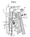
- Fig.2 is an enlarged sectional view of essential portions of Fig.1;
- Fig.3 is a view taken along a line 3-3 in Fig.2;
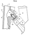
- Fig.4 is an enlarged view of
Area 4 in Fig.2; - Fig.5 is a sectional view taken along a line 5-5 in Fig.4;
- Fig.6 is an enlarged view of
Area 6 in Fig.5; - Fig.7 is a front view of a second bush (a view taken from a direction of an
arrow 7 in Fig.8); - Fig.8 is a sectional view taken along a line 8-8 in Fig.7;
- Fig.9 is a view taken from a direction of an
arrow 9 in Fig. 8; - Fig.10 is a view for explaining the operation during tilting-up;
- Fig.11 is a view taken from a direction of an
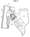
arrow 11 in Fig.10; and - Fig.12 is a view for explaining the operation during adjustment of a trim angle.
- Fig.13 is a view similar to Fig.3, but according to a second embodiment of the present invention.
- Figs. 14 and 15 show a third embodiment of the present invention, wherein Fig.14 is a view similar to Fig.6; and Fig.15 is a view taken along a line 15-15 in Fig.14.
- Fig.16 is a view similar to Fig.6, but according to a fourth embodiment of the present invention.
- A first embodiment of the present invention will now be described with reference to Figs.1 to 12.
- As shown in Fig.1, a propelling unit U constituting a body portion of an outboard engine system O includes a
support case assembly 11 and agear case 12 coupled to a lower portion of thesupport case assembly 11. A water-cooled multi-cylinder 4-stroke engine E is mounted at an upper portion of thesupport case assembly 11 with itscrankshaft 13 disposed vertically. Anengine cover 14 is openably and closably mounted at an upper end of thesupport case assembly 11 to cover the engine E. In the present application, thesupport case assembly 11 is a general term including a mount case which supports a main block of the engine E, an extension case coupled to a lower portion of the mount case, and an undercover which covers peripheries of the mount case and the extension case and receives theengine cover 14 to cover the engine E. - A
drive shaft 15 disposed vertically within thesupport case assembly 11 is connected to acrankshaft 13 of the engine E.A propeller shaft 17 mounting apropeller 16 at its rear end is supported within thegear case 12. A forward and backwardmovement switchover mechanism 18 connecting thedriver shaft 15 to thepropeller shaft 17 is housed in thegear case 12. Therefore, a driving force transmitted from thecrankshaft 13 to thedrive shaft 15 during operation of the engine E is transmitted through the forward and backwardmovement switchover mechanism 18 to thepropeller shaft 17, and the direction of rotation of thepropeller shaft 17 is controlled by the forward and backwardmovement switchover mechanism 18. - A vertically-extending
swivel shaft 21 is secured at its opposite ends to anupper arm 19 supporting an upper portion of thesupport case assembly 11 and a lower arm 20 supporting a lower portion of thesupport case assembly 11. Aswivel case 22 rotatably supporting theswivel shaft 21 is connected through ahorizontal tilting shaft 24 to upper portions of a pair of left andright stern brackets swivel case 22 from the left and right and clamped to a transom T of a hull. Therefore, the propellingunit Uof the outboard engine system O can vertically swing about thetilting shaft 24, and the outboard engine system O is divided into thestern brackets swivel case 22 and the propelling unit U which can swing with respect to the hull. - As can be seen from Figs. 2 and 3, the
swivel case 22 includes acylindrical case section 25 which directly supports theswivel shaft 21, and anarm section 26 extending forwards (toward the hull) from an upper portion of thecase section 25 and supported on thetilting shaft 24. A laterally-extendingupper pivot 27 is supported at its opposite ends within thearm section 26. A tiltingcylinder 29 is pivotally supported at its lower end on alower pivot 28 laid laterally at lower portions of the pair of left andright stern brackets cylinder rod 29a protruding from an upper end of the tiltingcylinder 29 is pivotally supported on theupper pivot 27. - As can be seen from Figs.4 and 5, a pair of
trim cylinders cylinder 29, andtrim rods trim cylinders portions case section 25 of theswivel case 22, andthrust receivers 32 having the same structure are mounted on the thrust receiver-supportingportions - As can be seen from Fig. 6, the
thrust receiver 32 is integrally provided with a bar-shaped shaft portion 32a and a disk-shapedpressure receiving portion 32b. Theshaft portion 32a is rotatably supported on afirst bush 33 and asecond bush 34 which are press-fitted into asupport bore 31a formed so as to pass through the thrust receiver-supportingportion 31. Thepressure receiving portion 32b is integrally formed at an end of theshaft portion 32a on thesecond bush 34 side, and anut 38 is threadedly fitted over a tip end of theshaft portion 32a protruding from thefirst bush 33 with threewashers thrust receiver 32 is fixed in a slip-off preventing manner. Thepressure receiving portion 32b has a surface depressed in a partially spherical shape, and a rounded tip end of thetrim rod 30a is placed into abutment against the spherical surface. By placing the plurality ofwashers first bushes 33 and theshaft portion 32a. - An axis L2 of the
shaft portion 32a of thethrust receiver 32 is generally parallel to an axis L1 of thetrim rod 30a of thetrim cylinder 30 as viewed from sideways (see Fig. 4), but the axis L2 of theshaft portion 32a of thethrust receiver 32 is displaced laterally by a distance α from the axis L1 of thetrim rod 30a of thetrim cylinder 30, as viewed in plane. Therefore, an abutment point P between thetrim rod 30a and thepressure receiving portion 32b of thethrust receiver 32 is displaced laterally by a distance β from the axis L2 of theshaft portion 32a of the thrust receiver 32 (see Fig.6). - As can be seen from Figs.6 and 7 to 9, the
second bush 34 includes acylindrical portion 34a and aflange portion 34b. Six oil grooves g1 are formed in thecylindrical portion 34a to extend in a direction of the axis L2. Six blind oil grooves g2 are formed radially in an outer surface of theflange portion 34b and connected to the six oil grooves g1, respectively. In a state in which the first andsecond bushes thrust receiver 32 are mounted in the support bore 31a in the thrust receiver-supportingportion 31, the oil grooves g1 in thesecond bush 34 are opposed to an outer peripheral surface of theshaft portion 32a of thethrust receiver 32, and the second oil grooves g2 in thesecond bush 34 are opposed to the back of thepressure receiving portion 32b of thethrust receiver 32. - An
oil passage 31b formed in the thrust receiver-supportingportion 31 communicates with anannular oil reservoir 31c which is formed between the first andsecond bushes second bush 34.Grease 39 is charged from anipple 40 provided in a grease charging bore 31d opening into an outer surface of the thrust receiver-supportingportion 31, through theoil passage 31b and theoil reservoir 31c, into the oil grooves g1 and g2. - The operation of the first embodiment having the above-described arrangement will be described below.
- As shown in Figs. 10 and 11, when the tilting
cylinder 29 is driven for expansion to cause thecylinder rod 29a to protrude, thearm section 26 of theswivel case 22 is pushed up through theupper pivot 27, whereby the propelling unit U integral with theswivel case 22 is swung about the tiltingshaft 24 provided at the upper end of thestern brackets trim rods trim cylinders thrust receivers - A thrust force generated by the
propeller 16 during operation of the outboard engine system O causes the propelling unit U to swing in a counterclockwise direction in Fig.1 about the tiltingshaft 24, but this thrust force is transmitted from the pair ofthrust receivers swivel case 22 through thetrim cylinders cylinder 29 and thestern brackets - To adjust the trim angle of the propelling unit U with respect of the hull, for example, the
trim cylinders trim rods portions swivel case 22 are urged backwards, whereby the propelling unit U is slightly swung about the tiltingshaft 24, thereby finely adjusting the thrust shaft of thepropeller 16 into a backward ascending inclination. On the other hand, when thetrim cylinders trim rods propeller 16 is finely adjusted into a backward descending inclination. - In the process of the above-described adjustment of the trim angle, the locus of movement of the
thrust receiver 32 draws an arc L3 of a circle about the tiltingshaft 24 as shown in Fig.2, while the locus of movement of thetrim rod 30a of thetrim cylinder 30 is generally in line with the axis L1. When the locus of movement of thethrust receiver 32 and the locus of movement of thetrim rod 30a are not in line with each other, as described above, there is a possibility that a twisting is generated at the abutment point P (see Fig. 6) between the tip end of thetrim rod 30a and thepressure receiving portion 32b of thethrust receiver 32 to generate an abnormal sound. - In the present embodiment, however, the
pressure receiving portion 32b of thethrust receiver 32 can be rotated freely about the axis L2 of theshaft portion 32a, and the abutment point P is displaced laterally by the distance β from the axis L2 of theshaft portion 32a of the thrust receiver 32 (see Fig.6). Therefore, the twisting can be effectively suppressed to reduce the generation of the abnormal sound by the free rotation of thethrust receiver 32 accompanying the expansion or contraction of thetrim rod 30a. Thethrust receiver 32 is supported on the thrust receiver-supportingportion 31 by utilizing theshaft portion 32a which serves as the axis for rotation of thethrust receiver 32, thus contributing to simplification of the structure. - At this time, the tip end of the
trim rod 30a is moved generally linearly on the axis L1, while thepressure receiving portion 32b of thethrust receiver 32 is rotated about the axis L2. Therefore, a slipping is generated between thetrim rod 30a and thepressure receiving portion 32b, but this slipping cannot generate an abnormal sound, because it is extremely slight. - In this way, the generation of the twisting can be suppressed to reduce the abnormal sound by only supporting the
thrust receiver 32 for rotation without disposition of a ball on either thetrim rod 30a or thethrust receiver 32 for bringing both of them into rolling contact with each other. This can simplify the structure to contribute to a reduction in cost. Moreover, it is not necessary to roll a ball on a tip end face of thetrim rod 30a, and hence the diameter of thetrim rod 30a can be decreased. - When the thrust force generated by the propelling unit U is transmitted from the
thrust receiver 32 to thetrim rod 30a, the thrust force acting on thepressure receiving portion 32b of thethrust receiver 32 is supported on the thrust receiver-supportingportion 31 of theswivel case 32 through theflange portion 34b of thesecond bush 34. At this time, the lubricant filled in theoil reservoir 31c is supplied through the oil grooves g1 in theshaft portion 34a of thesecond bush 34 into the oil grooves g2 in theflange portion 34b, and hence thethrust receiver 32 can be rotated even under a large thrust force, thereby effectively suppressing the generation of an abnormal sound. Of course, the lubricant supplied to the oil grooves g1 lubricates sliding surfaces between theshaft portion 32a of thethrust receiver 32 and thecylindrical portion 34a of thesecond bush 34. - The bush section is bisected into the first and
second bushes oil reservoir 31c is formed between the first andsecond bushes oil reservoir 31c, but also to reliably supply the lubricant to both the first andsecond bushes oil reservoir 31c to the sliding surfaces. Moreover, theoil reservoir 31c communicates with thegrease charging bore 31d in the surface of the thrust receiver-supportingportion 31 through theoil passage 31b, and hence the supply of the lubricant can be carried out without separating thethrust receiver 32 from the thrust receiver-supportingportion 31, leading to an enhanced maintenance property. - A second embodiment of the present invention will now be described with reference to Fig.13.
- In the first embodiment, the
shaft portion 32a of thethrust receiver 32 is fixed in a slip-off preventing manner by thenut 38, but in the second embodiment, ashaft portion 32a of athrust receiver 32 is fixed in the slip-off preventing manner by acisclip 41 in place of thenut 38. According to the second embodiment, the mounting and removing of thethrust receiver 32 are further facilitated, leading to an enhanced maintenance property. - A third embodiment of the present invention will now be described with reference to Figs.14 and 15.
- In the first embodiment, the abutment point P between he pressure receiving
portion 32b of thethrust receiver 32 and thetrim rod 30a is not lubricated, but in the third embodiment, the abutment point P is lubricated by lubricant from anoil reservoir 31c. More specifically,oil passages shaft portion 32a of athrust receiver 32 to provide a communication between surfaces of theoil reservoir 31a and thepressure receiving portion 32b, and a plurality of (two in the embodiment) oil grooves g3 are formed in the surface of thepressure receiving portion 32b to extend radially from an outlet of theoil passage 32d. Thus, the abutment point P between thepressure receiving portion 32b of thethrust receiver 32 and thetrim rod 30a can be lubricated to further reduce an abnormal sound during adjustment of the trim angle. The oil grooves g3 as non-contact portions are out of a range (a contact portion t) of a locus of the abutment point P of thetrim rod 30a, and lubricant can be supplied to the contact point P existing in,the contact portion t, while preventing thetrim rod 30a from contacting the oil grooves g3 and obstructing the smooth movement. - The oil grooves g3 may be provided in all radial directions in correspondence to the rotation of the
thrust receiver 32. - A fourth embodiment of the present invention will now be described with reference to Fig.16.
- The fourth embodiment is different from the first embodiment (see Fig.6) with respect to the structure of a
thrust receiver 32. Thethrust receiver 32 in the fourth embodiment includes aball holder 44 which is fitted into asupport bore 31c in a thrust receiver-supportingportion 31 and fixed by awasher 42 and anut 43. A ball-retainingportion 44a is formed at a tip end of theball holder 44 protruding from the thrust receiver-supportingportion 31, and aball 45 is rotatably supported within the ball-retainingportion 44a to abut against a flat tip end face of atrim rod 30a for rolling. Anoil passage 31b and anoil reservoir 31c are formed in the thrust receiver-supportingportion 31 to lead to anipple 40. Theoil reservoir 31c communicates with aspace 46 formed between the ball-retainingportion 44a and theball 45 throughoil passages 44b and 44c formed within theball holder 44. - Thus, when the
trim rod 30a of thetrim cylinder 30 is expanded or contracted to adjust the trim angle of the propelling unit U, theball 45 is rolled on the tip end face of thetrim rod 30a, thereby suppressing the generation of an abnormal sound. During this time,grease 39 supplied from agrease charging bore 31d fills theoil passage 31b, theoil reservoir 31c, theoil passages 44b and 44c and thespace 46, thereby enabling the smooth rotation of theball 45 relative to the ball-retainingportion 44a. - According also to the fourth embodiment, sliding portions between the ball-retaining
portion 44a and theball 45 can be lubricated over a long period by thegrease 39 stored in theoil passage 31b, theoil reservoir 31c, theoil passages 44b and 44c and thespace 46, and moreover thegrease 39 can be easily supplied from the outside using thenipple 40. - Although the embodiments of the present invention have been described in detail, various modifications in design may be made without departing from the subject matter of the invention.
- For example, in each of the embodiments, the
trim cylinders stern brackets thrust receivers thrust receivers stern brackets - Also, in the embodiments, the lubricant for lubricating the abutment point P between the pressure-receiving
portion 32b of thethrust receiver 32 and thetrim rod 30a is supplied from the side of thethrust receiver 32, but may be supplied from the side of thetrim rod 30a.
Claims (7)
- An outboard engine system comprising:a system body having a propeller shaft;a mounting device for mounting the system body to a hull for tilting movement;a trim device having an expandable and contractable trim rod mounted on one of the system body and the mounting device; anda thrust receiver mounted on the other of the system body and the mounting device to support a thrust force of the system body transmitted through the trim rod of the trim device,wherein the thrust receiver includes: a shaft portion supported for rotation about an axis generally parallel to an axis of the trim rod; and a pressure-receiving portion provided at one end of the shaft portion to abut against a tip end of the trim rod; and
wherein an abutment point between the tip end of the trim rod and the pressure-receiving portion of the thrust receiver is displaced from the axis of the shaft portion in a lateral direction of the system body. - An outboard engine system according to claim 1, wherein the shaft portion of the thrust receiver also serves as a mounting portion.
- An outboard engine system according to claim 1 or 2, further comprising a lubricant-supplying means for supplying lubricant to a surface of the pressure-receiving portion of the thrust receiver.
- An outboard engine system according to any preceding claim, wherein the thrust receiver is mounted for movement relative to at least one of the trim rod and the system body, and the system further includes a lubricant-retaining portion for supplying lubricant to portions moved relative to each other.
- An outboard engine system according to claim 4, wherein the thrust receiver has, on its surface abutting against the trim rod, a contact portion and a non-contact portion with the trim rod so that lubricant is supplied from the lubricant-retaining portion through the non-contact portion to the contact portion.
- An outboard engine system according to claim 4 or 5, wherein the thrust receiver comprises a rolling member rotatably retained on a holding member so that lubricant is supplied from the lubricant-retaining portion to a non-contact portion between the rolling member and the holding member.
- An outboard engine system according to any preceding claim, wherein a sliding portion is formed at a portion of the thrust receiver, and the sliding portion has a lubricant charging bore for charging lubricant from outside to the sliding portion.
Applications Claiming Priority (2)
| Application Number | Priority Date | Filing Date | Title |
|---|---|---|---|
| JP2004337820A JP2006143066A (en) | 2004-11-22 | 2004-11-22 | Outboard motor |
| JP2004337819A JP4271129B2 (en) | 2004-11-22 | 2004-11-22 | Outboard motor |
Publications (3)
| Publication Number | Publication Date |
|---|---|
| EP1659275A2 true EP1659275A2 (en) | 2006-05-24 |
| EP1659275A3 EP1659275A3 (en) | 2009-06-17 |
| EP1659275B1 EP1659275B1 (en) | 2010-10-06 |
Family
ID=35967193
Family Applications (1)
| Application Number | Title | Priority Date | Filing Date |
|---|---|---|---|
| EP05257179A Expired - Lifetime EP1659275B1 (en) | 2004-11-22 | 2005-11-22 | Outboard engine system |
Country Status (2)
| Country | Link |
|---|---|
| US (1) | US7351125B2 (en) |
| EP (1) | EP1659275B1 (en) |
Cited By (1)
| Publication number | Priority date | Publication date | Assignee | Title |
|---|---|---|---|---|
| WO2023230807A1 (en) * | 2022-05-31 | 2023-12-07 | 烟台聪铭经贸有限公司 | Electric propeller for boat |
Families Citing this family (5)
| Publication number | Priority date | Publication date | Assignee | Title |
|---|---|---|---|---|
| US8858279B1 (en) | 2011-05-31 | 2014-10-14 | Brp Us Inc. | Tilt/trim and steering bracket assembly for a marine outboard engine |
| US8851944B1 (en) | 2012-12-20 | 2014-10-07 | Brp Us Inc. | Marine engine hydraulic system |
| JP5982721B2 (en) * | 2013-01-15 | 2016-08-31 | ヤマハ発動機株式会社 | Suspension device for outboard motor and ship equipped with the device |
| US9675942B1 (en) * | 2013-10-15 | 2017-06-13 | Aeration Industries International, LLC. | Universal bridge and wall mounted aeration apparatus |
| JP2020124996A (en) * | 2019-02-04 | 2020-08-20 | 株式会社ショーワ | Outboard engine lifting device and outboard engine |
Citations (3)
| Publication number | Priority date | Publication date | Assignee | Title |
|---|---|---|---|---|
| JPS61132199U (en) | 1985-02-07 | 1986-08-18 | ||
| JPS62100297U (en) | 1985-12-16 | 1987-06-26 | ||
| JPH0891298A (en) | 1994-09-26 | 1996-04-09 | Honda Motor Co Ltd | Outboard trim device |
Family Cites Families (8)
| Publication number | Priority date | Publication date | Assignee | Title |
|---|---|---|---|---|
| US3912343A (en) * | 1974-04-03 | 1975-10-14 | Hamilton Neil King Paton | Vehicle side bearing and friction damper |
| US4362514A (en) * | 1980-09-04 | 1982-12-07 | Outboard Marine Corporation | High performance stern drive unit |
| DE3443032C1 (en) | 1984-11-26 | 1986-04-30 | H. Putsch Gmbh & Co, 5800 Hagen | Cutting disc machine, in particular for cutting sugar beet |
| JPS62100297A (en) | 1985-10-24 | 1987-05-09 | Japan Organo Co Ltd | Method of increasing yield of cyclodextrin |
| JPS62155193A (en) * | 1985-12-27 | 1987-07-10 | Sanshin Ind Co Ltd | Trim device for ship propeller |
| JPS62166192A (en) * | 1986-01-17 | 1987-07-22 | Sanshin Ind Co Ltd | Trim device of propelling machine of ship |
| JP3957103B2 (en) * | 1998-02-12 | 2007-08-15 | ヤマハマリン株式会社 | Ship propulsion device trim equipment |
| JP3543945B2 (en) * | 2000-03-22 | 2004-07-21 | 株式会社ショーワ | Tilt device for ship propulsion |
-
2005
- 2005-11-21 US US11/282,953 patent/US7351125B2/en not_active Expired - Lifetime
- 2005-11-22 EP EP05257179A patent/EP1659275B1/en not_active Expired - Lifetime
Patent Citations (3)
| Publication number | Priority date | Publication date | Assignee | Title |
|---|---|---|---|---|
| JPS61132199U (en) | 1985-02-07 | 1986-08-18 | ||
| JPS62100297U (en) | 1985-12-16 | 1987-06-26 | ||
| JPH0891298A (en) | 1994-09-26 | 1996-04-09 | Honda Motor Co Ltd | Outboard trim device |
Cited By (1)
| Publication number | Priority date | Publication date | Assignee | Title |
|---|---|---|---|---|
| WO2023230807A1 (en) * | 2022-05-31 | 2023-12-07 | 烟台聪铭经贸有限公司 | Electric propeller for boat |
Also Published As
| Publication number | Publication date |
|---|---|
| EP1659275A3 (en) | 2009-06-17 |
| US7351125B2 (en) | 2008-04-01 |
| US20060135007A1 (en) | 2006-06-22 |
| EP1659275B1 (en) | 2010-10-06 |
Similar Documents
| Publication | Publication Date | Title |
|---|---|---|
| US9139275B2 (en) | Suspension device for outboard motor and vessel propulsion apparatus | |
| JP4482442B2 (en) | vehicle | |
| EP1659275B1 (en) | Outboard engine system | |
| US8795010B1 (en) | Drive unit mount for a marine outboard engine | |
| US4720278A (en) | Trimming device for marine propulsion unit | |
| US9611023B2 (en) | Outboard motor for a watercraft and methods of use and manufacture thereof | |
| US9879719B2 (en) | Supporting structure for gear of outboard motor | |
| US8707854B2 (en) | Hydraulic cylinder device and boat propelling apparatus including the same | |
| US4764134A (en) | Trimming device for marine propulsion unit | |
| US10119564B2 (en) | Supporting structure for gear of outboard motor | |
| JP4271129B2 (en) | Outboard motor | |
| US5716247A (en) | Bearing arrangement for marine transmission | |
| US5597333A (en) | Trim system for outboard engine system | |
| JP2006143066A (en) | Outboard motor | |
| CN101006259A (en) | Rotation support for an assembly | |
| CA2254004C (en) | Marine propulsion system | |
| JP2017128307A (en) | Outboard engine mount device | |
| CN1470431A (en) | outboard motor | |
| US8087958B2 (en) | Boat propulsion system | |
| JP3038937B2 (en) | Outboard motor trim / tilt device | |
| US20040107795A1 (en) | Power transmission mechanism for an engine of a vehicle | |
| US20260070640A1 (en) | Boat propulsion device and boat | |
| JP2000318689A (en) | Outboard motor mounting structure | |
| EP1092849B1 (en) | Internal combustion engine | |
| CN219956282U (en) | In-chamber travelling mechanism for artillery |
Legal Events
| Date | Code | Title | Description |
|---|---|---|---|
| PUAI | Public reference made under article 153(3) epc to a published international application that has entered the european phase |
Free format text: ORIGINAL CODE: 0009012 |
|
| AK | Designated contracting states |
Kind code of ref document: A2 Designated state(s): AT BE BG CH CY CZ DE DK EE ES FI FR GB GR HU IE IS IT LI LT LU LV MC NL PL PT RO SE SI SK TR |
|
| AX | Request for extension of the european patent |
Extension state: AL BA HR MK YU |
|
| PUAL | Search report despatched |
Free format text: ORIGINAL CODE: 0009013 |
|
| AK | Designated contracting states |
Kind code of ref document: A3 Designated state(s): AT BE BG CH CY CZ DE DK EE ES FI FR GB GR HU IE IS IT LI LT LU LV MC NL PL PT RO SE SI SK TR |
|
| AX | Request for extension of the european patent |
Extension state: AL BA HR MK YU |
|
| RIC1 | Information provided on ipc code assigned before grant |
Ipc: B63H 20/10 20060101ALI20090511BHEP Ipc: F02B 61/04 20060101AFI20060314BHEP |
|
| 17P | Request for examination filed |
Effective date: 20090904 |
|
| 17Q | First examination report despatched |
Effective date: 20091009 |
|
| AKX | Designation fees paid |
Designated state(s): FR GB NL |
|
| GRAP | Despatch of communication of intention to grant a patent |
Free format text: ORIGINAL CODE: EPIDOSNIGR1 |
|
| REG | Reference to a national code |
Ref country code: DE Ref legal event code: 8566 |
|
| GRAS | Grant fee paid |
Free format text: ORIGINAL CODE: EPIDOSNIGR3 |
|
| GRAA | (expected) grant |
Free format text: ORIGINAL CODE: 0009210 |
|
| AK | Designated contracting states |
Kind code of ref document: B1 Designated state(s): FR GB NL |
|
| REG | Reference to a national code |
Ref country code: GB Ref legal event code: FG4D |
|
| REG | Reference to a national code |
Ref country code: NL Ref legal event code: T3 |
|
| PLBE | No opposition filed within time limit |
Free format text: ORIGINAL CODE: 0009261 |
|
| STAA | Information on the status of an ep patent application or granted ep patent |
Free format text: STATUS: NO OPPOSITION FILED WITHIN TIME LIMIT |
|
| 26N | No opposition filed |
Effective date: 20110707 |
|
| PGFP | Annual fee paid to national office [announced via postgrant information from national office to epo] |
Ref country code: NL Payment date: 20141108 Year of fee payment: 10 |
|
| REG | Reference to a national code |
Ref country code: FR Ref legal event code: PLFP Year of fee payment: 11 |
|
| PGFP | Annual fee paid to national office [announced via postgrant information from national office to epo] |
Ref country code: GB Payment date: 20151118 Year of fee payment: 11 |
|
| PGFP | Annual fee paid to national office [announced via postgrant information from national office to epo] |
Ref country code: FR Payment date: 20151008 Year of fee payment: 11 |
|
| REG | Reference to a national code |
Ref country code: NL Ref legal event code: MM Effective date: 20151201 |
|
| PG25 | Lapsed in a contracting state [announced via postgrant information from national office to epo] |
Ref country code: NL Free format text: LAPSE BECAUSE OF NON-PAYMENT OF DUE FEES Effective date: 20151201 |
|
| GBPC | Gb: european patent ceased through non-payment of renewal fee |
Effective date: 20161122 |
|
| REG | Reference to a national code |
Ref country code: FR Ref legal event code: ST Effective date: 20170731 |
|
| PG25 | Lapsed in a contracting state [announced via postgrant information from national office to epo] |
Ref country code: FR Free format text: LAPSE BECAUSE OF NON-PAYMENT OF DUE FEES Effective date: 20161130 |
|
| PG25 | Lapsed in a contracting state [announced via postgrant information from national office to epo] |
Ref country code: GB Free format text: LAPSE BECAUSE OF NON-PAYMENT OF DUE FEES Effective date: 20161122 |