EP1659248A1 - Floating damper - Google Patents
Floating damper Download PDFInfo
- Publication number
- EP1659248A1 EP1659248A1 EP05024154A EP05024154A EP1659248A1 EP 1659248 A1 EP1659248 A1 EP 1659248A1 EP 05024154 A EP05024154 A EP 05024154A EP 05024154 A EP05024154 A EP 05024154A EP 1659248 A1 EP1659248 A1 EP 1659248A1
- Authority
- EP
- European Patent Office
- Prior art keywords
- gear
- damper
- component
- base
- damper assembly
- Prior art date
- Legal status (The legal status is an assumption and is not a legal conclusion. Google has not performed a legal analysis and makes no representation as to the accuracy of the status listed.)
- Granted
Links
Images

Classifications
-
- A—HUMAN NECESSITIES
- A47—FURNITURE; DOMESTIC ARTICLES OR APPLIANCES; COFFEE MILLS; SPICE MILLS; SUCTION CLEANERS IN GENERAL
- A47B—TABLES; DESKS; OFFICE FURNITURE; CABINETS; DRAWERS; GENERAL DETAILS OF FURNITURE
- A47B88/00—Drawers for tables, cabinets or like furniture; Guides for drawers
- A47B88/40—Sliding drawers; Slides or guides therefor
- A47B88/473—Braking devices, e.g. linear or rotational dampers or friction brakes; Buffers; End stops
-
- E—FIXED CONSTRUCTIONS
- E05—LOCKS; KEYS; WINDOW OR DOOR FITTINGS; SAFES
- E05F—DEVICES FOR MOVING WINGS INTO OPEN OR CLOSED POSITION; CHECKS FOR WINGS; WING FITTINGS NOT OTHERWISE PROVIDED FOR, CONCERNED WITH THE FUNCTIONING OF THE WING
- E05F5/00—Braking devices, e.g. checks; Stops; Buffers
-
- F—MECHANICAL ENGINEERING; LIGHTING; HEATING; WEAPONS; BLASTING
- F16—ENGINEERING ELEMENTS AND UNITS; GENERAL MEASURES FOR PRODUCING AND MAINTAINING EFFECTIVE FUNCTIONING OF MACHINES OR INSTALLATIONS; THERMAL INSULATION IN GENERAL
- F16F—SPRINGS; SHOCK-ABSORBERS; MEANS FOR DAMPING VIBRATION
- F16F9/00—Springs, vibration-dampers, shock-absorbers, or similarly-constructed movement-dampers using a fluid or the equivalent as damping medium
- F16F9/10—Springs, vibration-dampers, shock-absorbers, or similarly-constructed movement-dampers using a fluid or the equivalent as damping medium using liquid only; using a fluid of which the nature is immaterial
- F16F9/12—Devices with one or more rotary vanes turning in the fluid any throttling effect being immaterial, i.e. damping by viscous shear effect only
-
- E—FIXED CONSTRUCTIONS
- E05—LOCKS; KEYS; WINDOW OR DOOR FITTINGS; SAFES
- E05F—DEVICES FOR MOVING WINGS INTO OPEN OR CLOSED POSITION; CHECKS FOR WINGS; WING FITTINGS NOT OTHERWISE PROVIDED FOR, CONCERNED WITH THE FUNCTIONING OF THE WING
- E05F5/00—Braking devices, e.g. checks; Stops; Buffers
- E05F5/02—Braking devices, e.g. checks; Stops; Buffers specially for preventing the slamming of swinging wings during final closing movement, e.g. jamb stops
-
- E—FIXED CONSTRUCTIONS
- E05—LOCKS; KEYS; WINDOW OR DOOR FITTINGS; SAFES
- E05F—DEVICES FOR MOVING WINGS INTO OPEN OR CLOSED POSITION; CHECKS FOR WINGS; WING FITTINGS NOT OTHERWISE PROVIDED FOR, CONCERNED WITH THE FUNCTIONING OF THE WING
- E05F5/00—Braking devices, e.g. checks; Stops; Buffers
- E05F5/06—Buffers or stops limiting opening of swinging wings, e.g. floor or wall stops
-
- E—FIXED CONSTRUCTIONS
- E05—LOCKS; KEYS; WINDOW OR DOOR FITTINGS; SAFES
- E05Y—INDEXING SCHEME ASSOCIATED WITH SUBCLASSES E05D AND E05F, RELATING TO CONSTRUCTION ELEMENTS, ELECTRIC CONTROL, POWER SUPPLY, POWER SIGNAL OR TRANSMISSION, USER INTERFACES, MOUNTING OR COUPLING, DETAILS, ACCESSORIES, AUXILIARY OPERATIONS NOT OTHERWISE PROVIDED FOR, APPLICATION THEREOF
- E05Y2201/00—Constructional elements; Accessories therefor
- E05Y2201/20—Brakes; Disengaging means; Holders; Stops; Valves; Accessories therefor
- E05Y2201/21—Brakes
-
- E—FIXED CONSTRUCTIONS
- E05—LOCKS; KEYS; WINDOW OR DOOR FITTINGS; SAFES
- E05Y—INDEXING SCHEME ASSOCIATED WITH SUBCLASSES E05D AND E05F, RELATING TO CONSTRUCTION ELEMENTS, ELECTRIC CONTROL, POWER SUPPLY, POWER SIGNAL OR TRANSMISSION, USER INTERFACES, MOUNTING OR COUPLING, DETAILS, ACCESSORIES, AUXILIARY OPERATIONS NOT OTHERWISE PROVIDED FOR, APPLICATION THEREOF
- E05Y2201/00—Constructional elements; Accessories therefor
- E05Y2201/20—Brakes; Disengaging means; Holders; Stops; Valves; Accessories therefor
- E05Y2201/252—Type of friction
- E05Y2201/254—Fluid or viscous friction
-
- E—FIXED CONSTRUCTIONS
- E05—LOCKS; KEYS; WINDOW OR DOOR FITTINGS; SAFES
- E05Y—INDEXING SCHEME ASSOCIATED WITH SUBCLASSES E05D AND E05F, RELATING TO CONSTRUCTION ELEMENTS, ELECTRIC CONTROL, POWER SUPPLY, POWER SIGNAL OR TRANSMISSION, USER INTERFACES, MOUNTING OR COUPLING, DETAILS, ACCESSORIES, AUXILIARY OPERATIONS NOT OTHERWISE PROVIDED FOR, APPLICATION THEREOF
- E05Y2201/00—Constructional elements; Accessories therefor
- E05Y2201/20—Brakes; Disengaging means; Holders; Stops; Valves; Accessories therefor
- E05Y2201/262—Type of motion, e.g. braking
- E05Y2201/266—Type of motion, e.g. braking rotary
-
- E—FIXED CONSTRUCTIONS
- E05—LOCKS; KEYS; WINDOW OR DOOR FITTINGS; SAFES
- E05Y—INDEXING SCHEME ASSOCIATED WITH SUBCLASSES E05D AND E05F, RELATING TO CONSTRUCTION ELEMENTS, ELECTRIC CONTROL, POWER SUPPLY, POWER SIGNAL OR TRANSMISSION, USER INTERFACES, MOUNTING OR COUPLING, DETAILS, ACCESSORIES, AUXILIARY OPERATIONS NOT OTHERWISE PROVIDED FOR, APPLICATION THEREOF
- E05Y2900/00—Application of doors, windows, wings or fittings thereof
- E05Y2900/50—Application of doors, windows, wings or fittings thereof for vehicles
- E05Y2900/53—Type of wing
- E05Y2900/538—Interior lids
Definitions
- the present invention relates generally to movement damper devices and, more particularly, to small gear dampers using damping media or fluid as the damping means.
- Dampers have many applications and uses for controlling the movement of things. Dampers are found often in automotive applications such as, for example, glove boxes doors, cup holders, assist handles and the like. Dampers are used to control the natural gravitational movement of such components and to provide a desired "feel" to movement of the component. Uses for dampers in assemblies other than automobiles are also known, such as, for example and not by way of limitation, furniture, appliances, electronic equipment and other assemblies with movable components.
- a known damper design that has been used with frequency provides resistance to the movement of a gear on the component to be controlled through driving engagement between the gear of the component and a gear of the damper.
- the damper gear is on a rotor, and resistance to rotation of the rotor and damper gear is inherent in the structure of the damper. Resistance to rotation of the damper gear is imparted to the movement of the gear on the component through driving engagement of the damper gear and the gear on the component. Movement of the component is thereby controlled.
- Such damping devices frequently are referred to as gear dampers.
- a gear damper of the type described is known to include a rotor rotatably held in a housing.
- An external gear is mounted on a shaft of the rotor projecting outwardly from the housing.
- Resistance to a rotation of the rotor is provided in part by a viscous fluid contained in a chamber within the housing, through which viscous fluid the rotor must spin.
- gear dampers of this type A problem with the use of gear dampers of this type is that unless the mating gears are manufactured within a tight range of tolerances, the gears can either be placed too far apart so as not to engage with each other properly or too close together such that the gears have a tendency to bind.
- Floating dampers have been used to address these problems in some applications. However, in other applications for gear dampers, simply providing a floating damper does not adequately meet the needs. Depending on the application, maintaining engagement of the gears is not insured by simply providing a damper that floats. Further, build variations and tolerances inherent in automotive and other devices cause gear teeth to skew relative to each other and lose engagement or bind. Prolonged use and wear can cause further shifting of associated components, exacerbating the problem.
- the present invention provides a floating damper that includes a bearing surface or guide member adapted to ride in a mating slot of an associated component.
- the bearing surface and slot ensure properly aligned engagement between gears of the damper and of the associated component.
- the present invention provides a damper assembly for first and second associated components movable relative to each other.
- a gear damper housing is mounted adjustably on the first component.
- a rotor shaft projects outwardly from the housing, and a damper gear is drivingly disposed on the rotor shaft.
- a bearing surface of the damper is in fixed location relative to the damper gear.
- a second gear is disposed on the second component and is engaged with the damper gear.
- a guide surface of the second component is disposed in a fixed position with respect to the second gear. The guide surface engages the bearing surface of the damper.
- the present invention provides a damper assembly for first and second components movable relative to each other.
- a damper is adjustably attached to the first component.
- a rotatable shaft extends outwardly of the damper.
- a first gear is disposed on the shaft for rotation therewith.
- a second gear is attached to the second component.
- a channel is defined in the second component. The first and second gears are drivingly engaged with each other. A distal end outwardly of the first gear is disposed in the channel.
- the present invention provides a gear damper assembly with a gear damper having a first gear and a bearing surface in fixed position relative to the first gear; a second gear engaged with the first gear, a guide surface provided in fixed position relative to the second gear; and the bearing surface engaging the guide surface.
- An advantage of the present invention is providing a gear damper that floats to minimize drift and control spacing between a gear of the damper and a gear of an associated component.
- Another advantage of the present invention is providing a gear damper that maintains proper alignment and engagement between a gear of the damper and a gear of an associated component.
- Still another advantage of the present invention is providing a gear damper assembly that compensates for tolerance stack-up and build variations in the damper and a structure on which the damper operates.
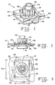
- Fig. 1 is a perspective view of a gear damper in accordance with the present invention
- Fig. 2 is a vertical view of the damper shown in Fig. 1 illustrated installed in a mounting plate or component of a device, which is shown in cross-section;
- Fig. 3 is a plan view of the installed damper shown in Fig. 2;
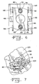
- Fig. 4 is an exploded view of an alternate form of a damper in accordance with the present invention.
- Fig. 5 is a cross-sectional view of the completed damper assembly shown in Fig. 4;
- Fig. 6 is a plan view of the damper shown in Figs. 4 and 5;
- Fig. 7 is a fragmentary view of a damper of the present invention installed in the associated components.
- damper 10 designates a damper of the present invention which can be used for mounting in a first component 12 of a device (Fig. 2) which may be a door, framework or panels of a glove box or accessory compartment; a cup holder or the like in an automobile; or drawers, doors, devices and things in other apparatuses and structures such as furniture, appliances, electronic components and the like. It is anticipated that damper 10 of the present invention will have a wide range of uses and applications, and should not be interpreted as being limited to the few applications and uses provided as examples herein.
- Damper 10 includes a housing 14 and a rotor rotatably disposed therein.
- the rotor includes a shaft 16 that extends outwardly from housing 14.
- a gear 18 is drivingly connected to shaft 16 for rotation with shaft 16.
- a distal end defines a bearing surface 20 outwardly of damper gear 18.
- Shaft 16, damper gear 18 and bearing surface 20 can be formed as a single monolithic body. Alternatively, shaft 16 and gear 18 can be separate bodies subsequently connected, with bearing surface 20 being an outer end of shaft 16 extending through damper gear 18, or bearing surface 20 can an outer portion of damper gear 18.
- Housing 14 is a sealed structure and contains a damping fluid therein.
- the internal configuration of housing 14 and the portions of the rotor disposed therein are such as to provide controlled resistance to the rotation of rotor shaft 16 in at least one direction.
- the basic structures, functions and arrangements of gear dampers are well-known to those skilled in the art and will not be described in further detail herein.
- Damper housing 14 is affixed to a mounting base 22 by which damper 10 is secured to component 12.
- Housing 14 and base 22 can be formed of plastic as a monolithic body in a plastic molding process, for example. Housing 14 and base 22 also can be separately formed and attached to each other by welding, for example.
- Four snap-fit features 24, 26, 28 and 30 are provided on base 22 to secure damper 10 within an opening 32 in component 12. Snap-fit features 24, 26, 28 and 30 are substantially perpendicular to base 22 at the comers thereof, in the exemplary embodiment. It should be understood that fewer then four or more than four snap-fit features can be used, and can be located other than at the corners of base 22. Other locking structures consistent with the purposes to be described herein also can be used.
- Snap-fit features 24, 26, 28 and 30 have outwardly directed, tapered tabs 34, 36, 38 and 40, respectively, at the distal ends thereof.
- Two tabs 34, 36 on one side of base 22 extend in a same direction, and the remaining two tabs 38, 40 on an opposite side of base 22 extend in a same direction that is opposite to that of the first mention two tabs 34, 36.
- Opening 32 has a width indicated by line 42 of sufficient dimension to receive base 22 and proximal portions of snap-fit features 24, 26, 28 and 30. Width 22 is less than the full width between pairs of tabs 34, 36 and 38, 40 on opposite sides of base 22.
- tabs 34, 36, 38 and 40 cause inward deflection of features 24, 26, 28 and 30 as the features are pushed through opening 32.
- tabs 34, 36, 38 and 40 are pushed completely through opening 32, features 24, 26, 28 and 30 rebound outward, with tabs 34, 36, 38 and 40 extending over a surface of component 12 as shown in Fig. 3, thereby inhibiting withdrawal of damper 10 from opening 32.
- Opening 32 has a length indicated by the line designated with number 44. Length 44 is greater than the length of base 22, thereby allowing back and forth movement of base 22 relative to component 12.
- Spring arms 46, 48 are provided on opposite sides of base 22 and are compressed against component 12 when base 22 is secured to component 12 via snap-fit features 24, 26, 28 and 30. Spring arms 46, 48 provide a biasing force to prevent objectionable rattle or noise from the fit of base 22 against component 12, while still allowing for relative float between damper 10 and component 12 back and forth along length 44.
- Figs. 4-6 illustrate another configuration of a damper 60 in accordance with the present invention that can be secured to a component 62 through an opening 64.
- Damper 60 includes a number of structures similar to damper 10, including housing 14, shaft 16, damper gear 18, bearing surface 20 and spring arms 46, 48, all as described previously herein, and all of which are similarly numbered in Fig. 4-6 and in Figs 1-3.
- Damper housing 14 of damper 60 is affixed to a base 66 having elongated slots 68 and 70 therein.
- Screw bosses 72 and 74 are configured and arranged on component 62 to be received in slots 68 and 70.
- Fasteners 76 and 78 having collars 80 and 82, respectively, are inserted through slots 68 and 70 and are received in screw bosses 72 and 74.
- Collars 80 and 82 are sufficiently large to prevent pull-through in slots 68 and 70.
- base 66 can move slightly with respect to component 62, thereby permitting float of damper 60 in at least one line back and forth.
- Spring arms 46, 48 on opposite sides of base 66 and are compressed against component 62 when base 66 is secured via fasteners 76, 78 in screw bosses 72 and 74. Fasteners 76, 78 and specifically collars 80, 82 thereof tighten against screw bosses 72, 74 without base 66 being compressed tightly against component 62. A space 84 remains between base 66 and component 62. Spring arms 46, 48 provide a biasing force to prevent objectionable rattle or noise from base 66 against component 62.
- Guide blocks 86, 88, 90 and 92 are provided on component 62 to position and restrict damper 60.
- Fig. 6 shows in plan view the positioning of base 66 between guide blocks 86, 88, 90 and 92, as well as the orientation of fasteners 76 and 78 within slots 68, 70.
- Fig. 5 shows the mounting in cross-section, through guide blocks 86 and 90 as well as screw boss 70 and fastener 76 disposed therein.
- Dampers 10, 60 of the present invention are configured and arranged in components 12, 62, respectively to operate with and control movement relative to a second associated component 100, as shown in Fig.7.
- Associated component 100 includes a gear 102 configured for engagement with gear 18.
- Gear 102 can be of various different types and configurations, and in the exemplary embodiment gear 102 is a straight gear or rack gear engaging damper gear 18. It should be understood that second gear 102 also can be various other types of gears, including generally circular type gears.
- Associated component 100 further defines a guide surface in the form of a channel 104. The distal end of rotor shaft 16 defining bearing surface 20 outwardly of gear 18 is received in channel 104.
- Bearing surface 20 of shaft 16 is provided in a fixed position relative to damper gear 18.
- Guide surface or channel 104 is provided in a fixed position relative to second gear 102.
- the interaction of bearing surface 20 and guide surface 104 ensures fixed relative positioning of damper gear 18 relative to second gear 102, thereby facilitating proper alignment and engagement of the gears.
- the adjustable, floating attachment of dampers 10, 60 to components 12, 62 further facilitates alignment and inhibits binding of the gears.
- the pitch diameters of damper gear 18 and second gear 102 remain tangent even as variations occur, and the damper follows the second gear through changes in relative location between the associated components 12 or 62 and 100.
Landscapes
- Engineering & Computer Science (AREA)
- General Engineering & Computer Science (AREA)
- Mechanical Engineering (AREA)
- Gears, Cams (AREA)
- Steering Controls (AREA)
Abstract
Description
- The present regular United States Patent Application claims the benefits of United States Provisional Patent Application Serial No. 60/629,044 filed November 18, 2004.
- The present invention relates generally to movement damper devices and, more particularly, to small gear dampers using damping media or fluid as the damping means.
- Small dampers have many applications and uses for controlling the movement of things. Dampers are found often in automotive applications such as, for example, glove boxes doors, cup holders, assist handles and the like. Dampers are used to control the natural gravitational movement of such components and to provide a desired "feel" to movement of the component. Uses for dampers in assemblies other than automobiles are also known, such as, for example and not by way of limitation, furniture, appliances, electronic equipment and other assemblies with movable components.
- A known damper design that has been used with frequency provides resistance to the movement of a gear on the component to be controlled through driving engagement between the gear of the component and a gear of the damper. The damper gear is on a rotor, and resistance to rotation of the rotor and damper gear is inherent in the structure of the damper. Resistance to rotation of the damper gear is imparted to the movement of the gear on the component through driving engagement of the damper gear and the gear on the component. Movement of the component is thereby controlled. Such damping devices frequently are referred to as gear dampers.
- A gear damper of the type described is known to include a rotor rotatably held in a housing. An external gear is mounted on a shaft of the rotor projecting outwardly from the housing. Resistance to a rotation of the rotor is provided in part by a viscous fluid contained in a chamber within the housing, through which viscous fluid the rotor must spin.
- A problem with the use of gear dampers of this type is that unless the mating gears are manufactured within a tight range of tolerances, the gears can either be placed too far apart so as not to engage with each other properly or too close together such that the gears have a tendency to bind. Floating dampers have been used to address these problems in some applications. However, in other applications for gear dampers, simply providing a floating damper does not adequately meet the needs. Depending on the application, maintaining engagement of the gears is not insured by simply providing a damper that floats. Further, build variations and tolerances inherent in automotive and other devices cause gear teeth to skew relative to each other and lose engagement or bind. Prolonged use and wear can cause further shifting of associated components, exacerbating the problem.
- The present invention provides a floating damper that includes a bearing surface or guide member adapted to ride in a mating slot of an associated component. The bearing surface and slot ensure properly aligned engagement between gears of the damper and of the associated component.
- In one form thereof, the present invention provides a damper assembly for first and second associated components movable relative to each other. A gear damper housing is mounted adjustably on the first component. A rotor shaft projects outwardly from the housing, and a damper gear is drivingly disposed on the rotor shaft. A bearing surface of the damper is in fixed location relative to the damper gear. A second gear is disposed on the second component and is engaged with the damper gear. A guide surface of the second component is disposed in a fixed position with respect to the second gear. The guide surface engages the bearing surface of the damper.
- In another form thereof, the present invention provides a damper assembly for first and second components movable relative to each other. A damper is adjustably attached to the first component. A rotatable shaft extends outwardly of the damper. A first gear is disposed on the shaft for rotation therewith. A second gear is attached to the second component. A channel is defined in the second component. The first and second gears are drivingly engaged with each other. A distal end outwardly of the first gear is disposed in the channel.
- In a still further form thereof, the present invention provides a gear damper assembly with a gear damper having a first gear and a bearing surface in fixed position relative to the first gear; a second gear engaged with the first gear, a guide surface provided in fixed position relative to the second gear; and the bearing surface engaging the guide surface.
- An advantage of the present invention is providing a gear damper that floats to minimize drift and control spacing between a gear of the damper and a gear of an associated component.
- Another advantage of the present invention is providing a gear damper that maintains proper alignment and engagement between a gear of the damper and a gear of an associated component.
- Still another advantage of the present invention is providing a gear damper assembly that compensates for tolerance stack-up and build variations in the damper and a structure on which the damper operates.
- Other features and advantages of the invention will become apparent to those skilled in the art upon review of the following detailed description, claims and drawings in which like numerals are used to designate like features.
- Fig. 1 is a perspective view of a gear damper in accordance with the present invention;
- Fig. 2 is a vertical view of the damper shown in Fig. 1 illustrated installed in a mounting plate or component of a device, which is shown in cross-section;
- Fig. 3 is a plan view of the installed damper shown in Fig. 2;
- Fig. 4 is an exploded view of an alternate form of a damper in accordance with the present invention;
- Fig. 5 is a cross-sectional view of the completed damper assembly shown in Fig. 4;
- Fig. 6 is a plan view of the damper shown in Figs. 4 and 5; and
- Fig. 7 is a fragmentary view of a damper of the present invention installed in the associated components.
- Before the embodiments of the invention are explained in detail, it is to be understood that the invention is not limited in its application to the details of construction and the arrangements of the components set forth in the following description or illustrated in the drawings. The invention is capable of other embodiments and of being practiced or being carried out in various ways. Also, it is understood that the phraseology and terminology used herein are for the purpose of description and should not be regarded as limiting. The use herein of "including", "comprising" and variations thereof is meant to encompass the items listed thereafter and equivalents thereof, as well as additional items and equivalents thereof.
- Referring now more specifically to the drawings and to Fig. 1 in particular,
numeral 10 designates a damper of the present invention which can be used for mounting in afirst component 12 of a device (Fig. 2) which may be a door, framework or panels of a glove box or accessory compartment; a cup holder or the like in an automobile; or drawers, doors, devices and things in other apparatuses and structures such as furniture, appliances, electronic components and the like. It is anticipated thatdamper 10 of the present invention will have a wide range of uses and applications, and should not be interpreted as being limited to the few applications and uses provided as examples herein. -
Damper 10 includes ahousing 14 and a rotor rotatably disposed therein. The rotor includes ashaft 16 that extends outwardly fromhousing 14. Agear 18 is drivingly connected toshaft 16 for rotation withshaft 16. A distal end defines abearing surface 20 outwardly ofdamper gear 18.Shaft 16,damper gear 18 and bearingsurface 20 can be formed as a single monolithic body. Alternatively,shaft 16 andgear 18 can be separate bodies subsequently connected, with bearingsurface 20 being an outer end ofshaft 16 extending throughdamper gear 18, or bearingsurface 20 can an outer portion ofdamper gear 18. -
Housing 14 is a sealed structure and contains a damping fluid therein. The internal configuration ofhousing 14 and the portions of the rotor disposed therein are such as to provide controlled resistance to the rotation ofrotor shaft 16 in at least one direction. The basic structures, functions and arrangements of gear dampers are well-known to those skilled in the art and will not be described in further detail herein. -
Damper housing 14 is affixed to a mountingbase 22 by whichdamper 10 is secured tocomponent 12.Housing 14 andbase 22 can be formed of plastic as a monolithic body in a plastic molding process, for example.Housing 14 andbase 22 also can be separately formed and attached to each other by welding, for example. Four snap-fit features 24, 26, 28 and 30 are provided onbase 22 to securedamper 10 within anopening 32 incomponent 12. Snap-fit features 24, 26, 28 and 30 are substantially perpendicular tobase 22 at the comers thereof, in the exemplary embodiment. It should be understood that fewer then four or more than four snap-fit features can be used, and can be located other than at the corners ofbase 22. Other locking structures consistent with the purposes to be described herein also can be used. - Snap-fit features 24, 26, 28 and 30 have outwardly directed, tapered
tabs tabs base 22 extend in a same direction, and the remaining twotabs base 22 extend in a same direction that is opposite to that of the first mention twotabs Opening 32 has a width indicated byline 42 of sufficient dimension to receivebase 22 and proximal portions of snap-fit features 24, 26, 28 and 30.Width 22 is less than the full width between pairs oftabs base 22. The tapered distal faces oftabs features opening 32. Astabs opening 32, features 24, 26, 28 and 30 rebound outward, withtabs component 12 as shown in Fig. 3, thereby inhibiting withdrawal ofdamper 10 from opening 32. -
Opening 32 has a length indicated by the line designated withnumber 44.Length 44 is greater than the length ofbase 22, thereby allowing back and forth movement ofbase 22 relative tocomponent 12.Spring arms base 22 and are compressed againstcomponent 12 whenbase 22 is secured tocomponent 12 via snap-fit features 24, 26, 28 and 30.Spring arms base 22 againstcomponent 12, while still allowing for relative float betweendamper 10 andcomponent 12 back and forth alonglength 44. - Snap-fit attachment of
damper 10 todevice 14 can speed assembly for many uses ofdamper 10. However, in some uses of the present invention it may be desirable to use removable fasteners. Figs. 4-6 illustrate another configuration of adamper 60 in accordance with the present invention that can be secured to acomponent 62 through anopening 64.Damper 60 includes a number of structures similar todamper 10, includinghousing 14,shaft 16,damper gear 18, bearingsurface 20 andspring arms -
Damper housing 14 ofdamper 60 is affixed to a base 66 having elongatedslots Screw bosses component 62 to be received inslots Fasteners collars slots screw bosses Collars slots screw bosses fasteners hold base 66 relative tocomponent 62. However, because of the elongated configuration ofslots base 66 can move slightly with respect tocomponent 62, thereby permitting float ofdamper 60 in at least one line back and forth. -
Spring arms base 66 and are compressed againstcomponent 62 whenbase 66 is secured viafasteners screw bosses Fasteners collars screw bosses base 66 being compressed tightly againstcomponent 62. Aspace 84 remains betweenbase 66 andcomponent 62.Spring arms base 66 againstcomponent 62. - Guide blocks 86, 88, 90 and 92 are provided on
component 62 to position and restrictdamper 60. Fig. 6 shows in plan view the positioning ofbase 66 between guide blocks 86, 88, 90 and 92, as well as the orientation offasteners slots screw boss 70 andfastener 76 disposed therein. -
Dampers components component 100, as shown in Fig.7.Associated component 100 includes agear 102 configured for engagement withgear 18.Gear 102 can be of various different types and configurations, and in theexemplary embodiment gear 102 is a straight gear or rack gear engagingdamper gear 18. It should be understood thatsecond gear 102 also can be various other types of gears, including generally circular type gears.Associated component 100 further defines a guide surface in the form of achannel 104. The distal end ofrotor shaft 16 definingbearing surface 20 outwardly ofgear 18 is received inchannel 104. - Bearing
surface 20 ofshaft 16 is provided in a fixed position relative todamper gear 18. Guide surface orchannel 104 is provided in a fixed position relative tosecond gear 102. The interaction of bearingsurface 20 andguide surface 104 ensures fixed relative positioning ofdamper gear 18 relative tosecond gear 102, thereby facilitating proper alignment and engagement of the gears. The adjustable, floating attachment ofdampers components damper gear 18 andsecond gear 102 remain tangent even as variations occur, and the damper follows the second gear through changes in relative location between the associatedcomponents - Variations and modifications of the foregoing are within the scope of the present invention. It is understood that the invention disclosed and defined herein extends to all alternative combinations of two or more of the individual features mentioned or evident from the text and/or drawings. All of these different combinations constitute various alternative aspects of the present invention. The embodiments described herein explain the best modes known for practicing the invention and will enable others skilled in the art to utilize the invention. The claims are to be construed to include alternative embodiments to the extent permitted by the prior art.
- Various features of the invention are set forth in the following claims.
Claims (20)
- A damper assembly comprising:first and second associated components movable relative to each other;a gear damper housing adjustably mounted on the first component;a rotor shaft projecting outwardly from said housing;a damper gear drivingly disposed on said rotor shaft;a bearing surface of said damper in fixed location relative to said damper gear;a second gear disposed on said second component and drivingly engaged with said damper gear; anda guide surface of said second component disposed in a fixed position with respect to said second gear, said guide surface engaging said bearing surface of said damper.
- The damper assembly of claim 1, said bearing surface being a distal end outwardly of said damper gear.
- The damper assembly of claim 1, said guide surface being a channel in said second component.
- The damper assembly of claim 1, said bearing surface being a distal end outwardly of said damper gear and said guide surface comprising a channel in said second component, with said distal end being received in said channel.
- The damper assembly of claim 4, said second gear being a rack gear.
- The damper assembly of claim 4, including a base extending outwardly of said housing and snap-fit features disposed on said base engaging said first component.
- The damper assembly of claim 4, including a base attached to and extending outwardly of said housing, snap-fit features disposed on said base; and an opening in said first component receiving said base and said snap-fit features, said opening being larger than said base in at least one direction allowing relative movement between said base and said first component.
- The damper assembly of claim 4, including a base attached to said housing, said base defining elongated slots therein, said first component defining bosses, and fasteners extending through said slots into said bosses.
- The damper assembly of claim 4, including a base connected to said housing, said base being adjustably attached to said first component, and said base including spring arms engaging said first component.
- The damper assembly of claim 1, including a base connected to said housing, and snap-fit features disposed on said base and attaching said base to said first component.
- The damper assembly of claim 10, said base including spring arms engaging said first component.
- The damper assembly of claim 1, including a base connected to said housing, snap-fit features on said base; and an opening in said first component receiving said base and said snap-fit features, said opening being larger than said base in at least one direction allowing relative movement between said base and said first component.
- The damper assembly of claim 12, said base including spring arms engaging said first component.
- A damper assembly comprising:first and second components movable relative to each other;a damper adjustably attached to said first component;a rotatable shaft extending outwardly of said damper;a first gear disposed on said shaft for rotation therewith;a second gear attached to said second component;a channel defined in said second component;said first and second gears being drivingly engaged with each other; anda distal end outwardly of said first gear being disposed in said channel.
- The damper assembly of claim 14, said first component defining an opening and said damper being slidably secured in said opening.
- The damper assembly of claim 15, said damper including snap-fit features engaging said opening.
- The damper assembly of claim 15, said damper including a base having elongated slots therein, said first component defining fastener bosses aligned with said slots and fasteners extending through said slots into said bosses.
- A gear damper assembly comprising:a gear damper having a first gear and a bearing surface in fixed position relative to said first gear;a second gear engaged with said first gear;a guide surface provided in fixed position relative to said second gear; andsaid bearing surface engaging said guide surface.
- The gear damper assembly of claim 18, said bearing surface being a distal end outwardly of said first gear.
- The gear damper assembly of claim 18, said guide surface being a channel.
Applications Claiming Priority (2)
| Application Number | Priority Date | Filing Date | Title |
|---|---|---|---|
| US62904404P | 2004-11-18 | 2004-11-18 | |
| US11/197,032 US7350629B2 (en) | 2004-11-18 | 2005-08-04 | Floating damper |
Publications (2)
| Publication Number | Publication Date |
|---|---|
| EP1659248A1 true EP1659248A1 (en) | 2006-05-24 |
| EP1659248B1 EP1659248B1 (en) | 2012-06-06 |
Family
ID=35788274
Family Applications (1)
| Application Number | Title | Priority Date | Filing Date |
|---|---|---|---|
| EP05024154A Expired - Lifetime EP1659248B1 (en) | 2004-11-18 | 2005-11-05 | Floating damper |
Country Status (3)
| Country | Link |
|---|---|
| US (1) | US7350629B2 (en) |
| EP (1) | EP1659248B1 (en) |
| CA (1) | CA2525163C (en) |
Cited By (3)
| Publication number | Priority date | Publication date | Assignee | Title |
|---|---|---|---|---|
| WO2011031614A1 (en) * | 2009-09-08 | 2011-03-17 | Illinois Tool Works Inc. | Damper with integrated light and switch for a glove compartment door |
| CN105401818A (en) * | 2014-09-04 | 2016-03-16 | 现代摩比斯株式会社 | Structure Of Damper For Glove Box |
| EP3624641B1 (en) * | 2017-05-18 | 2023-01-11 | Schock Metallwerk GmbH | Guide device |
Families Citing this family (15)
| Publication number | Priority date | Publication date | Assignee | Title |
|---|---|---|---|---|
| DE102004055654B4 (en) * | 2004-11-15 | 2007-11-29 | Faurecia Innenraum Systeme Gmbh | Storage compartment device |
| US7959201B2 (en) * | 2008-07-29 | 2011-06-14 | Honda Motor Co., Ltd. | Gear damper |
| US7850219B2 (en) * | 2008-10-08 | 2010-12-14 | Gm Global Technology Operations, Inc. | Viscous rotary damper for vehicle end gate assembly |
| WO2010096229A1 (en) * | 2009-02-23 | 2010-08-26 | Illinois Tool Works Inc. | Damper assembly and device utilizing the same |
| USD644086S1 (en) * | 2010-07-12 | 2011-08-30 | Dr. Hahn GmbH & Co. LG | Slide damper |
| DE102010039139B4 (en) * | 2010-08-10 | 2017-01-19 | Lisa Dräxlmaier GmbH | Guide device with tolerance compensation |
| DE202010018071U1 (en) * | 2010-11-11 | 2013-11-21 | Wittenstein Ag | Flange for fixing a gearbox or electric motor |
| WO2012092930A2 (en) * | 2011-01-03 | 2012-07-12 | Pressalit A/S | Toilet hinge arrangement |
| US9382965B2 (en) | 2011-11-07 | 2016-07-05 | Illinois Tool Works Inc. | Self-aligning rotary damper assembly |
| US9481401B2 (en) * | 2014-05-09 | 2016-11-01 | Continental Automotive Systems, Inc. | Adjustable and flexible damper structure for instrument clusters |
| JP6573292B2 (en) * | 2016-05-11 | 2019-09-11 | 株式会社パイオラックス | Opening and closing body locking device |
| JP6282694B2 (en) * | 2016-07-14 | 2018-02-21 | 株式会社ソリック | Backlash prevention rack and pinion gear |
| KR101996289B1 (en) * | 2017-12-22 | 2019-07-04 | 주식회사 니프코코리아 | Flow Protection Device of Damper for Glovebox |
| JP6453497B2 (en) * | 2018-01-24 | 2019-01-16 | 株式会社ソリック | Backlash prevention rack and pinion gear in double sliding door device |
| US12560015B2 (en) * | 2018-06-06 | 2026-02-24 | Schlage Lock Company Llc | Door hardware noise reduction and evaluation |
Citations (5)
| Publication number | Priority date | Publication date | Assignee | Title |
|---|---|---|---|---|
| DE19505985A1 (en) * | 1995-02-21 | 1996-08-22 | Paulmann & Crone Gmbh & Co Kg | Storage compartment in motor vehicle e.g. glove box |
| US5887930A (en) * | 1995-11-16 | 1999-03-30 | Itw-Ateco Gmbh | Device for damping the movement of a movably supported structural part, in particular of a flap in an automotive vehicle of the like |
| US20020170143A1 (en) * | 2001-05-12 | 2002-11-21 | Fabrice Vitry | Detented and dampened hinge mechanism |
| EP1503111A2 (en) * | 2003-07-31 | 2005-02-02 | Nifco Inc. | Damper device |
| WO2005066523A1 (en) * | 2004-01-09 | 2005-07-21 | Nifco Inc. | Braking device |
Family Cites Families (5)
| Publication number | Priority date | Publication date | Assignee | Title |
|---|---|---|---|---|
| US5658058A (en) * | 1995-05-12 | 1997-08-19 | Illinois Tool Works Inc. | Floating gear damper |
| DE19729900C1 (en) * | 1997-07-12 | 1998-10-01 | Daimler Benz Ag | Damping device e.g. for motor vehicle glove box |
| US6848759B2 (en) * | 2002-04-03 | 2005-02-01 | Illinois Tool Works Inc. | Self-closing slide mechanism with damping |
| US6910557B2 (en) * | 2003-01-29 | 2005-06-28 | Illinois Tool Works Inc. | Slide damper with spring assist |
| US7044529B2 (en) * | 2004-09-30 | 2006-05-16 | Intier Automotive Inc. | Articulating door for a storage compartment |
-
2005
- 2005-08-04 US US11/197,032 patent/US7350629B2/en not_active Expired - Lifetime
- 2005-11-02 CA CA002525163A patent/CA2525163C/en not_active Expired - Fee Related
- 2005-11-05 EP EP05024154A patent/EP1659248B1/en not_active Expired - Lifetime
Patent Citations (5)
| Publication number | Priority date | Publication date | Assignee | Title |
|---|---|---|---|---|
| DE19505985A1 (en) * | 1995-02-21 | 1996-08-22 | Paulmann & Crone Gmbh & Co Kg | Storage compartment in motor vehicle e.g. glove box |
| US5887930A (en) * | 1995-11-16 | 1999-03-30 | Itw-Ateco Gmbh | Device for damping the movement of a movably supported structural part, in particular of a flap in an automotive vehicle of the like |
| US20020170143A1 (en) * | 2001-05-12 | 2002-11-21 | Fabrice Vitry | Detented and dampened hinge mechanism |
| EP1503111A2 (en) * | 2003-07-31 | 2005-02-02 | Nifco Inc. | Damper device |
| WO2005066523A1 (en) * | 2004-01-09 | 2005-07-21 | Nifco Inc. | Braking device |
Cited By (4)
| Publication number | Priority date | Publication date | Assignee | Title |
|---|---|---|---|---|
| WO2011031614A1 (en) * | 2009-09-08 | 2011-03-17 | Illinois Tool Works Inc. | Damper with integrated light and switch for a glove compartment door |
| CN105401818A (en) * | 2014-09-04 | 2016-03-16 | 现代摩比斯株式会社 | Structure Of Damper For Glove Box |
| US9937866B2 (en) | 2014-09-04 | 2018-04-10 | Hyundai Mobis Co., Ltd. | Structure of damper for glove box |
| EP3624641B1 (en) * | 2017-05-18 | 2023-01-11 | Schock Metallwerk GmbH | Guide device |
Also Published As
| Publication number | Publication date |
|---|---|
| EP1659248B1 (en) | 2012-06-06 |
| CA2525163C (en) | 2009-06-30 |
| CA2525163A1 (en) | 2006-05-18 |
| US20060102439A1 (en) | 2006-05-18 |
| US7350629B2 (en) | 2008-04-01 |
Similar Documents
| Publication | Publication Date | Title |
|---|---|---|
| US7350629B2 (en) | Floating damper | |
| US9297195B2 (en) | Hinge damper assembly | |
| EP2776652B1 (en) | Self-aligning rotary damper assembly | |
| US6553615B1 (en) | Two-piece sliding grommet | |
| US9505351B2 (en) | Mount for a motor-vehicle accessory | |
| US5658058A (en) | Floating gear damper | |
| CN100513828C (en) | Floating damper | |
| US10926720B2 (en) | Rubber spool grommets for assembly to vehicle | |
| DE102009002005A1 (en) | Position sensor i.e. four-bit position sensor, for detection of position of transmission element of motor vehicle, has compensating element reducing clearance in chain between movement of transmission element and movement of carriage | |
| EP1948961B1 (en) | Linear damper | |
| WO2018158361A1 (en) | Belt retractor having a noise-damped acceleration sensor | |
| JP4105411B2 (en) | Seat rail shoulder adjuster guide rail mounting structure | |
| DE19734499C2 (en) | Elastic suspension device for an exhaust system | |
| DE202005008840U1 (en) | Fractional horsepower permanent magnet DC motor brush holder for window lifter of vehicle has vibration damper to prevent contact bounce | |
| JP3221115U (en) | Rotary damper | |
| US20080093939A1 (en) | Quiet gear assembly | |
| WO2007082856A2 (en) | Structure borne noise securing element, securing system and sound-absorbing element comprising said type of securing element | |
| DE102018204780A1 (en) | Domestic appliance with an adjustment contour formed on a wall element | |
| JPS6234907B2 (en) | ||
| DE102004035464A1 (en) | Attachment device for side airbag module in vehicle has distal connector that abuts vehicle body when fixed bracket is completely installed into vehicle body | |
| KR20050056580A (en) | Jig for assembling a leg for use in an electronic device | |
| JP2007146482A (en) | Sliding door device | |
| DE102004054576A1 (en) | Bracket and mounting frame for mounting a device module | |
| EP1939562A2 (en) | Cooling device with electronic components | |
| DE29903347U1 (en) | Vehicle seat with a fan |
Legal Events
| Date | Code | Title | Description |
|---|---|---|---|
| PUAI | Public reference made under article 153(3) epc to a published international application that has entered the european phase |
Free format text: ORIGINAL CODE: 0009012 |
|
| 17P | Request for examination filed |
Effective date: 20051105 |
|
| AK | Designated contracting states |
Kind code of ref document: A1 Designated state(s): AT BE BG CH CY CZ DE DK EE ES FI FR GB GR HU IE IS IT LI LT LU LV MC NL PL PT RO SE SI SK TR |
|
| AX | Request for extension of the european patent |
Extension state: AL BA HR MK YU |
|
| 17Q | First examination report despatched |
Effective date: 20060814 |
|
| AKX | Designation fees paid |
Designated state(s): DE ES FR GB IT SE |
|
| GRAP | Despatch of communication of intention to grant a patent |
Free format text: ORIGINAL CODE: EPIDOSNIGR1 |
|
| GRAS | Grant fee paid |
Free format text: ORIGINAL CODE: EPIDOSNIGR3 |
|
| GRAA | (expected) grant |
Free format text: ORIGINAL CODE: 0009210 |
|
| AK | Designated contracting states |
Kind code of ref document: B1 Designated state(s): DE ES FR GB IT SE |
|
| REG | Reference to a national code |
Ref country code: GB Ref legal event code: FG4D |
|
| REG | Reference to a national code |
Ref country code: DE Ref legal event code: R096 Ref document number: 602005034502 Country of ref document: DE Effective date: 20120802 |
|
| PG25 | Lapsed in a contracting state [announced via postgrant information from national office to epo] |
Ref country code: SE Free format text: LAPSE BECAUSE OF FAILURE TO SUBMIT A TRANSLATION OF THE DESCRIPTION OR TO PAY THE FEE WITHIN THE PRESCRIBED TIME-LIMIT Effective date: 20120606 |
|
| PG25 | Lapsed in a contracting state [announced via postgrant information from national office to epo] |
Ref country code: IT Free format text: LAPSE BECAUSE OF FAILURE TO SUBMIT A TRANSLATION OF THE DESCRIPTION OR TO PAY THE FEE WITHIN THE PRESCRIBED TIME-LIMIT Effective date: 20120606 |
|
| PLBE | No opposition filed within time limit |
Free format text: ORIGINAL CODE: 0009261 |
|
| STAA | Information on the status of an ep patent application or granted ep patent |
Free format text: STATUS: NO OPPOSITION FILED WITHIN TIME LIMIT |
|
| PG25 | Lapsed in a contracting state [announced via postgrant information from national office to epo] |
Ref country code: ES Free format text: LAPSE BECAUSE OF FAILURE TO SUBMIT A TRANSLATION OF THE DESCRIPTION OR TO PAY THE FEE WITHIN THE PRESCRIBED TIME-LIMIT Effective date: 20120917 |
|
| 26N | No opposition filed |
Effective date: 20130307 |
|
| REG | Reference to a national code |
Ref country code: DE Ref legal event code: R097 Ref document number: 602005034502 Country of ref document: DE Effective date: 20130307 |
|
| GBPC | Gb: european patent ceased through non-payment of renewal fee |
Effective date: 20121105 |
|
| REG | Reference to a national code |
Ref country code: FR Ref legal event code: ST Effective date: 20130731 |
|
| PG25 | Lapsed in a contracting state [announced via postgrant information from national office to epo] |
Ref country code: GB Free format text: LAPSE BECAUSE OF NON-PAYMENT OF DUE FEES Effective date: 20121105 Ref country code: FR Free format text: LAPSE BECAUSE OF NON-PAYMENT OF DUE FEES Effective date: 20121130 |
|
| P01 | Opt-out of the competence of the unified patent court (upc) registered |
Effective date: 20230606 |
|
| PGFP | Annual fee paid to national office [announced via postgrant information from national office to epo] |
Ref country code: DE Payment date: 20241127 Year of fee payment: 20 |
|
| REG | Reference to a national code |
Ref country code: DE Ref legal event code: R071 Ref document number: 602005034502 Country of ref document: DE |