EP1659013A1 - Slide shoe and sunshade assembly provided therewith - Google Patents
Slide shoe and sunshade assembly provided therewith Download PDFInfo
- Publication number
- EP1659013A1 EP1659013A1 EP04105957A EP04105957A EP1659013A1 EP 1659013 A1 EP1659013 A1 EP 1659013A1 EP 04105957 A EP04105957 A EP 04105957A EP 04105957 A EP04105957 A EP 04105957A EP 1659013 A1 EP1659013 A1 EP 1659013A1
- Authority
- EP
- European Patent Office
- Prior art keywords
- slide
- slide shoe
- recess
- brake insert
- guide
- Prior art date
- Legal status (The legal status is an assumption and is not a legal conclusion. Google has not performed a legal analysis and makes no representation as to the accuracy of the status listed.)
- Withdrawn
Links
- 230000007423 decrease Effects 0.000 claims abstract description 4
- 230000036316 preload Effects 0.000 claims description 5
- 230000003247 decreasing effect Effects 0.000 claims description 4
- 230000000903 blocking effect Effects 0.000 claims description 3
- 230000007246 mechanism Effects 0.000 description 5
- 230000000694 effects Effects 0.000 description 4
- 238000004804 winding Methods 0.000 description 4
- 230000006835 compression Effects 0.000 description 1
- 238000007906 compression Methods 0.000 description 1
- 230000001419 dependent effect Effects 0.000 description 1
- 230000003292 diminished effect Effects 0.000 description 1
- 230000003467 diminishing effect Effects 0.000 description 1
- 230000008092 positive effect Effects 0.000 description 1
Images
Classifications
-
- B—PERFORMING OPERATIONS; TRANSPORTING
- B60—VEHICLES IN GENERAL
- B60J—WINDOWS, WINDSCREENS, NON-FIXED ROOFS, DOORS, OR SIMILAR DEVICES FOR VEHICLES; REMOVABLE EXTERNAL PROTECTIVE COVERINGS SPECIALLY ADAPTED FOR VEHICLES
- B60J1/00—Windows; Windscreens; Accessories therefor
- B60J1/20—Accessories, e.g. wind deflectors, blinds
- B60J1/2011—Blinds; curtains or screens reducing heat or light intensity
- B60J1/2013—Roller blinds
- B60J1/2036—Roller blinds characterised by structural elements
- B60J1/2044—Draw bars, including elements attached to it, e.g. sliding shoes, gripping elements or pull cords
-
- B—PERFORMING OPERATIONS; TRANSPORTING
- B60—VEHICLES IN GENERAL
- B60J—WINDOWS, WINDSCREENS, NON-FIXED ROOFS, DOORS, OR SIMILAR DEVICES FOR VEHICLES; REMOVABLE EXTERNAL PROTECTIVE COVERINGS SPECIALLY ADAPTED FOR VEHICLES
- B60J1/00—Windows; Windscreens; Accessories therefor
- B60J1/20—Accessories, e.g. wind deflectors, blinds
- B60J1/2011—Blinds; curtains or screens reducing heat or light intensity
- B60J1/2013—Roller blinds
- B60J1/2036—Roller blinds characterised by structural elements
- B60J1/2052—Guides
-
- B—PERFORMING OPERATIONS; TRANSPORTING
- B60—VEHICLES IN GENERAL
- B60J—WINDOWS, WINDSCREENS, NON-FIXED ROOFS, DOORS, OR SIMILAR DEVICES FOR VEHICLES; REMOVABLE EXTERNAL PROTECTIVE COVERINGS SPECIALLY ADAPTED FOR VEHICLES
- B60J7/00—Non-fixed roofs; Roofs with movable panels, e.g. rotary sunroofs
- B60J7/02—Non-fixed roofs; Roofs with movable panels, e.g. rotary sunroofs of sliding type, e.g. comprising guide shoes
Definitions
- the invention relates to a slide shoe having at least two opposite slide faces for cooperation with two corresponding slide surfaces of a guide.
- the cooperation between a slide shoe and a guide has to fulfil requirements which, sometimes, are opposite.
- the cooperation between the slide shoe and guide should be of such a kind that an exact positioning of the slide shoe within the guide occurs without undesired movements of the slide shoe and rattling noises resulting therefrom.
- the cooperation between the slide shoe and guide should be of such a kind, that the movement of the slide shoe relative to the guide is not obstructed in an undesired manner.
- a slide shoe having at least two opposite slide faces for cooperation with two corresponding slide surfaces of a guide, characterized in that at least one of said slide faces is provided with a wedge-shaped recess with a depth that increases/decreases in a direction aligned with the intended direction of movement of the slide shoe in the guide, wherein in the recess a wedge-shaped brake insert is positioned with a dimension in said direction of movement that is smaller than the corresponding dimension of the recess, such that the brake insert is movable in said recess in a direction aligned with said direction of movement of the slide shoe in the guide.
- the wedge-shaped brake insert engages a corresponding slide surface of the guide.
- friction will occur between the brake insert and said slide surface of the guide.
- the wedge-shaped brake insert is urged in the direction of decreasing depth of the recess, whereas when the slide shoe moves in the opposite direction relative to the guide the brake insert is urged in the opposite direction of increasing depth of the recess.
- the wedge-shape of the recess and of the brake insert will cause the brake insert to project in an increasing amount from the corresponding slide face of the slide shoe, thus engaging the corresponding slide surface of the guide with increasing frictional force.
- the brake insert will have a braking influence on the movement of the slide shoe relative to the guide.
- the wedge-shape of the recess and brake insert will cause the brake insert to retract in the recess, thus diminishing or even eliminating the braking effect due to friction force between the brake insert and corresponding slide surface of the guide.
- the brake insert is preloaded for a movement in the recess in the direction of decreasing depth of the recess.
- a preload can ensure that the braking effect of the brake insert will automatically start when the slide shoe is moved in the corresponding direction relative to the guide.
- the start of the braking effect of the brake insert in most time will depend on the gravitational force acting on the brake insert and pushing it into engagement with the corresponding slide surface of the guide. In such a case, however, the correct operation of the slide shoe would be dependent on its spatial orientation.
- a preload as mentioned before is applied, the operation of the slide shoe will be independent of its spatial orientation.
- the preload of the brake insert is generated by a spring member positioned between the slide shoe body and the brake insert.
- a spring member positioned between the slide shoe body and the brake insert.
- other possibilities are conceivable, such as the use of a resilient brake insert.
- abutment means are provided for limiting the movement of the brake insert in the recess. As a result the frictional forces acting between the brake insert and guide can be kept within limits.
- the abutment means are positioned in such a manner that a movement of the brake insert towards a position for completely blocking the slide shoe in the guide is prevented.
- a proper operation of the slide shoe will be guaranteed in all cases.
- the abutment means are settable, wear of the wedge-shaped brake insert can be taken care of. As a result, the effective lifespan of the slide shoe can be increased without the need for replacing its brake insert.
- abutment means could be provided, the constructional features of the slide shoe will be kept at a minimum level when the abutment means are defined by sidewalls of the brake shoe itself and corresponding side walls of the recess.
- the brake insert is positioned in the recess in a non-removable manner.
- Non-removable means, that the brake insert cannot fall out of the recess when the slide shoe is removed from the guide. Such a feature will have a positive effect on the ease of mounting a slide shoe.
- Such a non-removable position of the brake insert in the recess can, for example, be realised when the recess is provided with undercut grooves housing corresponding projections of the brake insert.
- a slide shoe in accordance with the present invention already operates effectively when it comprises only one brake insert of the type referred to before, it is also possible that both opposite slide faces of the slide shoe are provided with a wedge-shaped recess and wedge-shaped brake insert positioned therein. Whether only one or two brake inserts will be provided depends on the operating forces of the slide shoe.
- the invention further relates to a sunshade assembly, comprising a movable shading screen with a leading operating beam, wherein the beam has two outer ends provided with slide shoes cooperating with two guides and wherein the slide shoes are of the type according to the present invention.
- a sunshade assembly basically comprises a moveable shading screen 1 which, in the illustrated embodiment, is windable on and off a winding tube 2.
- said winding tube 2 may be preloaded in a direction for winding the shading screen thereon.
- the end of the shading screen remote from the winding tube 2 is provided with a leading operating beam 3 which, again in the illustrated embodiment, is provided with a grip 4 for manually moving the movable shading screen 1 to and fro.
- the operating beam 3 has two outer ends provided with slide shoes 5 which each cooperate with a guide 6.
- the guides 6 define the track of the shading screen 1 (as is know per se) and also could position the edges of the shading screen (not illustrated here).
- Slide shoe 5 has an upper slide face 7 for cooperation with an upper slide surface 8 of the guide 6.
- a lower slide face 9 of the slide shoe 5 is meant for cooperation with a lower slide surface 10 of the guide 6.
- the wedge-shaped recess 11 has a depth that increases or decreases (dependant upon the direction of observation) in a direction aligned with the intended direction of movement of the slide shoe 5 in the guide 6 (in figure 2 to the right/to the left).
- a wedge-shaped brake insert 12 is positioned with a dimension in said direction of movement that is smaller than the corresponding dimension of the recess 11 (i.e. in figure 2 the dimension from the left to the right).
- the brake insert 12 is movable in said recess 11 in a direction substantially aligned with said direction of movement of the slide shoe 5 in the guide 6 (differing therefrom only with the wedge angle).
- a compression spring 13 is positioned between the slide shoe body 5 and the brake insert 12, such that the brake insert 12 is preloaded to the left (as seen in figure 2).
- a movement of the slide shoe 5 in the opposite direction (arrow L) also will induce a frictional force between the lower surface of the brake insert 12 and the lower slide surface 10 of the guide 6, as a result of which the brake insert 12 will move to the right (as seen in figure 2) relative to the slide shoe body 5.
- the lower surface of the brake insert 12 will move away from the lower slide surface 10 of the guide 6, such that the braking force will be diminished or even eliminated.
- a wall portion 14 of the brake insert 12 and a corresponding wall portion 15 of the slide shoe body 5 may cooperate in an abutting manner, such that an end position of the brake insert 12 to the left is defined, in which no complete blocking of the slide shoe 5 in the guide 6 occurs.
- the wall portion 15 can be part of a settable part 16 of the slide shoe body. This has been illustrated schematically in figure 2 by a dotted line 17 which represents a setting screw or a like. Thus, it is possible to adjust the position of the wall portion 15 (and thus of the brake insert relative to the slide shoe body) to take into account wear of the lower surface of the brake insert 12.
- FIG 2 shows that the recess 11 comprises undercut grooves 18 and 19 housing corresponding projections 20 and 21 of the brake insert 12.
- the brake insert 12 is positioned in the recess 11 in a non-removable manner.
Landscapes
- Engineering & Computer Science (AREA)
- Mechanical Engineering (AREA)
- Operating, Guiding And Securing Of Roll- Type Closing Members (AREA)
Abstract
A slide shoe is presented having at least two opposite slide faces for cooperation with two corresponding slide surfaces of a guide. At least one of said slide faces is provided with a wedge-shaped recess with a depth that increases/decreases in a direction aligned with the intended direction of movement of the slide shoe in the guide, wherein in the recess a wedge-shaped brake insert is positioned with a dimension in said direction of movement that is smaller than the corresponding dimension of the recess, such that the brake insert is movable in said recess in a direction aligned with said direction of movement of the slide shoe in the guide.
Description
- Firstly, the invention relates to a slide shoe having at least two opposite slide faces for cooperation with two corresponding slide surfaces of a guide.
- The cooperation between a slide shoe and a guide has to fulfil requirements which, sometimes, are opposite. At one hand, the cooperation between the slide shoe and guide should be of such a kind that an exact positioning of the slide shoe within the guide occurs without undesired movements of the slide shoe and rattling noises resulting therefrom. At the other hand the cooperation between the slide shoe and guide should be of such a kind, that the movement of the slide shoe relative to the guide is not obstructed in an undesired manner. Of course, it would be possible to provide the slide shoe (or, whatever may be the case, the guide) with hand-operated clamping mechanisms which prevent undesired movements of the slide shoe relative to the guide, and thus will prevent disturbing noises. However, the use of such clamping mechanisms requires an additional operation (i.e. unlocking these mechanisms) before the slide shoe can be moved relative to the guide. Thus, such additional clamping mechanisms would render a slide shoe (or slide mechanism comprising such a slide shoe and guide) unnecessary complicated.
- It is an object of the present invention to provide an improved slide shoe of the type referred to above.
- Thus, in accordance with the present invention a slide shoe is presented having at least two opposite slide faces for cooperation with two corresponding slide surfaces of a guide, characterized in that at least one of said slide faces is provided with a wedge-shaped recess with a depth that increases/decreases in a direction aligned with the intended direction of movement of the slide shoe in the guide, wherein in the recess a wedge-shaped brake insert is positioned with a dimension in said direction of movement that is smaller than the corresponding dimension of the recess, such that the brake insert is movable in said recess in a direction aligned with said direction of movement of the slide shoe in the guide.
- In a slide shoe according to the present invention the wedge-shaped brake insert engages a corresponding slide surface of the guide. During movement of the slide shoe relative to the guide friction will occur between the brake insert and said slide surface of the guide. When the slide shoe moves in a first direction, the wedge-shaped brake insert is urged in the direction of decreasing depth of the recess, whereas when the slide shoe moves in the opposite direction relative to the guide the brake insert is urged in the opposite direction of increasing depth of the recess. When the brake insert is moved in the direction of decreasing depth of the recess, the wedge-shape of the recess and of the brake insert will cause the brake insert to project in an increasing amount from the corresponding slide face of the slide shoe, thus engaging the corresponding slide surface of the guide with increasing frictional force. Thus, in such a case the brake insert will have a braking influence on the movement of the slide shoe relative to the guide. However, when the slide shoe moves in the opposite direction and the brake insert is urged in the direction of increasing depth of the recess, the wedge-shape of the recess and brake insert will cause the brake insert to retract in the recess, thus diminishing or even eliminating the braking effect due to friction force between the brake insert and corresponding slide surface of the guide.
- The effects mentioned before occur automatically when the slide shoe moves relative to the guide, such that no additional operation is needed.
- In a preferred embodiment of the slide shoe according to the present invention the brake insert is preloaded for a movement in the recess in the direction of decreasing depth of the recess. Such a preload can ensure that the braking effect of the brake insert will automatically start when the slide shoe is moved in the corresponding direction relative to the guide. When such a preload is not available, the start of the braking effect of the brake insert in most time will depend on the gravitational force acting on the brake insert and pushing it into engagement with the corresponding slide surface of the guide. In such a case, however, the correct operation of the slide shoe would be dependent on its spatial orientation. When a preload as mentioned before is applied, the operation of the slide shoe will be independent of its spatial orientation.
- According to an effective embodiment of the slide shoe, the preload of the brake insert is generated by a spring member positioned between the slide shoe body and the brake insert. However, also other possibilities are conceivable, such as the use of a resilient brake insert.
- Further it is preferred, that abutment means are provided for limiting the movement of the brake insert in the recess. As a result the frictional forces acting between the brake insert and guide can be kept within limits.
- For example, the abutment means are positioned in such a manner that a movement of the brake insert towards a position for completely blocking the slide shoe in the guide is prevented. Thus a proper operation of the slide shoe will be guaranteed in all cases.
- When, in accordance with yet another embodiment of the slide shoe according to the present invention, the abutment means are settable, wear of the wedge-shaped brake insert can be taken care of. As a result, the effective lifespan of the slide shoe can be increased without the need for replacing its brake insert.
- Although distinct abutment means could be provided, the constructional features of the slide shoe will be kept at a minimum level when the abutment means are defined by sidewalls of the brake shoe itself and corresponding side walls of the recess.
- Further it is preferred that the brake insert is positioned in the recess in a non-removable manner. Non-removable means, that the brake insert cannot fall out of the recess when the slide shoe is removed from the guide. Such a feature will have a positive effect on the ease of mounting a slide shoe.
- Such a non-removable position of the brake insert in the recess can, for example, be realised when the recess is provided with undercut grooves housing corresponding projections of the brake insert.
- It should be clear, that parts of the brake shoe body defining the undercut groves generally will have to be removed temporarily before the brake insert with its corresponding projections can be positioned in the recess. For such a removability proper means can be provided, such as screws or alike.
- Although a slide shoe in accordance with the present invention already operates effectively when it comprises only one brake insert of the type referred to before, it is also possible that both opposite slide faces of the slide shoe are provided with a wedge-shaped recess and wedge-shaped brake insert positioned therein. Whether only one or two brake inserts will be provided depends on the operating forces of the slide shoe.
- The invention further relates to a sunshade assembly, comprising a movable shading screen with a leading operating beam, wherein the beam has two outer ends provided with slide shoes cooperating with two guides and wherein the slide shoes are of the type according to the present invention.
- Hereinafter the invention will be elucidated while referring to the drawing, in which an embodiment of a sunshade assembly and a slide shoe applied therein, are shown.
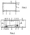
- Figure 1 shows, schematically, a top plan view of a sunshade assembly incorporating two slide shoes in accordance with the present invention, and
- figure 2 shows in side elevational view and on a larger scale an embodiment of a slide shoe according to the present invention.
- Firstly referring to figure 1, a sunshade assembly basically comprises a
moveable shading screen 1 which, in the illustrated embodiment, is windable on and off awinding tube 2. As is known per se, and not shown in detail here , saidwinding tube 2 may be preloaded in a direction for winding the shading screen thereon. - The end of the shading screen remote from the
winding tube 2 is provided with a leadingoperating beam 3 which, again in the illustrated embodiment, is provided with agrip 4 for manually moving themovable shading screen 1 to and fro. - The
operating beam 3 has two outer ends provided withslide shoes 5 which each cooperate with aguide 6. Theguides 6 define the track of the shading screen 1 (as is know per se) and also could position the edges of the shading screen (not illustrated here). - A preferred embodiment of a
slide shoe 5 is illustrated in figure 2.Slide shoe 5 has anupper slide face 7 for cooperation with anupper slide surface 8 of theguide 6. In a corresponding manner, alower slide face 9 of theslide shoe 5 is meant for cooperation with alower slide surface 10 of theguide 6. - In the
lower slide face 9 of the slide shoe 5 a wedge-shaped recess 11 is provided. The wedge-shaped recess 11 has a depth that increases or decreases (dependant upon the direction of observation) in a direction aligned with the intended direction of movement of theslide shoe 5 in the guide 6 (in figure 2 to the right/to the left). - In the recess 11 a wedge-
shaped brake insert 12 is positioned with a dimension in said direction of movement that is smaller than the corresponding dimension of the recess 11 (i.e. in figure 2 the dimension from the left to the right). Thebrake insert 12 is movable in saidrecess 11 in a direction substantially aligned with said direction of movement of theslide shoe 5 in the guide 6 (differing therefrom only with the wedge angle). - A
compression spring 13 is positioned between theslide shoe body 5 and thebrake insert 12, such that thebrake insert 12 is preloaded to the left (as seen in figure 2). - When the
slide shoe 5 is moved to the right (arrow R) friction occurring between the lower face of thebrake insert 12 and thelower slide surface 10 of theguide 6 will induce a movement of thebrake insert 12 to the left relative to theslide shoe body 5. As a result of the wedge shape of therecess 11 and brake insert 12 such a movement of thebrake insert 12 also will move its lower surface towards thelower slide surface 10 of theguide 6, thus creating a braking force (or an increase thereof). At the same time theupper face 7 of theslide shoe 5 andupper surface 8 of theguide 6 will engage each other with increasing force. - A movement of the
slide shoe 5 in the opposite direction (arrow L) also will induce a frictional force between the lower surface of thebrake insert 12 and thelower slide surface 10 of theguide 6, as a result of which thebrake insert 12 will move to the right (as seen in figure 2) relative to theslide shoe body 5. Again as a result of the wedge-shape of both elements now the lower surface of thebrake insert 12 will move away from thelower slide surface 10 of theguide 6, such that the braking force will be diminished or even eliminated. - A
wall portion 14 of the brake insert 12 and acorresponding wall portion 15 of theslide shoe body 5 may cooperate in an abutting manner, such that an end position of the brake insert 12 to the left is defined, in which no complete blocking of theslide shoe 5 in theguide 6 occurs. - In a special embodiment of the
slide shoe 5 thewall portion 15 can be part of asettable part 16 of the slide shoe body. This has been illustrated schematically in figure 2 by adotted line 17 which represents a setting screw or a like. Thus, it is possible to adjust the position of the wall portion 15 (and thus of the brake insert relative to the slide shoe body) to take into account wear of the lower surface of thebrake insert 12. - Finally figure 2 shows that the
recess 11 comprisesundercut grooves corresponding projections brake insert 12. Like this, thebrake insert 12 is positioned in therecess 11 in a non-removable manner. - The invention is not limited to the embodiment described before, which may be varied widely within the scope of the invention as defined by the appending claims.
Claims (11)
- Slide shoe having at least two opposite slide faces for cooperation with two corresponding slide surfaces of a guide, characterized in that at least one of said slide faces is provided with a wedge-shaped recess with a depth that increases/decreases in a direction aligned with the intended direction of movement of the slide shoe in the guide, wherein in the recess a wedge-shaped brake insert is positioned with a dimension in said direction of movement that is smaller than the corresponding dimension of the recess, such that the brake insert is movable in said recess in a direction aligned with said direction of movement of the slide shoe in the guide.
- Slide shoe according to claim 1, wherein the brake insert is preloaded for a movement in the recess in the direction of decreasing depth of the recess.
- Slide shoe according to claim 2, wherein the preload of the brake insert is generated by a spring member positioned between the slide shoe body and the brake insert.
- Slide shoe according to any of the previous claims, wherein abutment means are provided for limiting the movement of the brake insert in the recess.
- Slide shoe according to claim 4, wherein the abutment means are positioned in such a manner that a movement of the brake insert towards a position for completely blocking the slide shoe in the guide is prevented.
- Slide shoe according to claim 4 or 5, wherein the abutment means are settable.
- Slide shoe according to any of the claims 4-6, wherein the abutment means are defined by side walls of the brake shoe itself and corresponding side walls of the recess.
- Slide shoe according to any of the previous claims, wherein the brake insert is positioned in the recess in a non-removable manner.
- Slide shoe according to claim 8, wherein the recess is provided with undercut grooves housing corresponding projections of the brake insert.
- Slide shoe according to any of the previous claims, wherein both opposite slide faces of the slide shoe are provided with a wedge-shaped recess and wedge-shaped brake insert positioned therein.
- Sunshade assembly, comprising a movable shading screen with a leading operating beam, wherein the beam has two outer ends provided with slide shoes cooperating with two guides and wherein the slide shoes are of the type according to any of the previous claims.
Priority Applications (1)
| Application Number | Priority Date | Filing Date | Title |
|---|---|---|---|
| EP04105957A EP1659013A1 (en) | 2004-11-22 | 2004-11-22 | Slide shoe and sunshade assembly provided therewith |
Applications Claiming Priority (1)
| Application Number | Priority Date | Filing Date | Title |
|---|---|---|---|
| EP04105957A EP1659013A1 (en) | 2004-11-22 | 2004-11-22 | Slide shoe and sunshade assembly provided therewith |
Publications (1)
| Publication Number | Publication Date |
|---|---|
| EP1659013A1 true EP1659013A1 (en) | 2006-05-24 |
Family
ID=34929903
Family Applications (1)
| Application Number | Title | Priority Date | Filing Date |
|---|---|---|---|
| EP04105957A Withdrawn EP1659013A1 (en) | 2004-11-22 | 2004-11-22 | Slide shoe and sunshade assembly provided therewith |
Country Status (1)
| Country | Link |
|---|---|
| EP (1) | EP1659013A1 (en) |
Cited By (1)
| Publication number | Priority date | Publication date | Assignee | Title |
|---|---|---|---|---|
| EP1902880A1 (en) * | 2006-09-22 | 2008-03-26 | Wagon Sas | Concealing device with runners equipped with return means and corresponding vehicle. |
Citations (5)
| Publication number | Priority date | Publication date | Assignee | Title |
|---|---|---|---|---|
| DE2234852A1 (en) * | 1972-07-15 | 1974-01-24 | Audi Nsu Auto Union Ag | SLIDING CONSOLE WITH A RIGHT ANGLED SLIDING SHOE CARRIER FOR SLIDING ROOFS OF MOTOR VEHICLES IN RAILS |
| DE3044282A1 (en) * | 1979-12-24 | 1981-06-25 | Webasto-Werk W. Baier GmbH & Co, 8035 Gauting | Sliding roof panel low drag shoe - has sprung rollers in guide shoe with large locating spring |
| DE3425273A1 (en) * | 1984-07-10 | 1986-01-16 | Webasto-Werk W. Baier GmbH & Co, 8035 Gauting | Sliding shoe for a sliding roof of a vehicle |
| EP1232888A1 (en) * | 2001-01-19 | 2002-08-21 | Inalfa Industries B.V. | Protective cover for guide rail of a vehicle open roof construction |
| US20040068839A1 (en) * | 2002-09-30 | 2004-04-15 | Daniel Hock | Vehicle sunshade guide mechanism |
-
2004
- 2004-11-22 EP EP04105957A patent/EP1659013A1/en not_active Withdrawn
Patent Citations (5)
| Publication number | Priority date | Publication date | Assignee | Title |
|---|---|---|---|---|
| DE2234852A1 (en) * | 1972-07-15 | 1974-01-24 | Audi Nsu Auto Union Ag | SLIDING CONSOLE WITH A RIGHT ANGLED SLIDING SHOE CARRIER FOR SLIDING ROOFS OF MOTOR VEHICLES IN RAILS |
| DE3044282A1 (en) * | 1979-12-24 | 1981-06-25 | Webasto-Werk W. Baier GmbH & Co, 8035 Gauting | Sliding roof panel low drag shoe - has sprung rollers in guide shoe with large locating spring |
| DE3425273A1 (en) * | 1984-07-10 | 1986-01-16 | Webasto-Werk W. Baier GmbH & Co, 8035 Gauting | Sliding shoe for a sliding roof of a vehicle |
| EP1232888A1 (en) * | 2001-01-19 | 2002-08-21 | Inalfa Industries B.V. | Protective cover for guide rail of a vehicle open roof construction |
| US20040068839A1 (en) * | 2002-09-30 | 2004-04-15 | Daniel Hock | Vehicle sunshade guide mechanism |
Cited By (2)
| Publication number | Priority date | Publication date | Assignee | Title |
|---|---|---|---|---|
| EP1902880A1 (en) * | 2006-09-22 | 2008-03-26 | Wagon Sas | Concealing device with runners equipped with return means and corresponding vehicle. |
| FR2906188A1 (en) * | 2006-09-22 | 2008-03-28 | Wagons Sas Soc Par Actions Sim | OCCULTATION DEVICE WITH PATINS EQUIPPED WITH RECOVERY MEANS AND VEHICLE CORRESPONDING |
Similar Documents
| Publication | Publication Date | Title |
|---|---|---|
| EP2826944B1 (en) | Brake arrangement for a covering for architectural openings | |
| EP0818597B1 (en) | Rod-based file interlock system | |
| EP3372117B1 (en) | Coupling mechanism and slide rail assembly with cushioning function | |
| EP3461244B1 (en) | Slide rail assembly and driving mechanism thereof | |
| AU711315B2 (en) | Parking brake for motor vehicles, towed vehicles, or suchlike | |
| CN110017374A (en) | Parking lock casing | |
| EP3372114A1 (en) | Coupling mechanism and slide rail assembly for furniture part | |
| US20150375369A1 (en) | Detachable blocking device, in particular on a clamping tool | |
| EP3372115B1 (en) | Coupling mechanism and slide rail assembly for furniture part | |
| EP1659013A1 (en) | Slide shoe and sunshade assembly provided therewith | |
| US6902245B1 (en) | Drawer slide | |
| EP0373627A1 (en) | Mounting structure for electric devices | |
| JPH02200283A (en) | Heel binding for alpine ski | |
| US5517901A (en) | Linear drive having profile elements provided on flanks in a longitudinal slot of a guide tube | |
| KR101338265B1 (en) | System for the connection of two components, retaining member for said system, and mirror assembly for automotive vehicles equipped with said system | |
| EP3318354A1 (en) | Parting off blade and parting off machine | |
| HU213425B (en) | Device for blocking giude slider on sliding door's lower part of lift | |
| JP2867587B2 (en) | Drawer | |
| EP1685995B1 (en) | Guiding assembly and open roof construction provided therewith | |
| EP0896117A2 (en) | Closure device for sliding leaves | |
| JP6410666B2 (en) | Passenger conveyor | |
| DE202004021200U1 (en) | Guiding shoe e.g. for brake shoe, has sliding surfaces provided with wedge-shaped recess with height which increases or decreases in direction to align guiding shoe in direction of specified direction of motion | |
| EP2959801A1 (en) | Self-closing slide rail assembly and self-closing mechanism thereof | |
| JP7023148B2 (en) | Seat slide device | |
| CN112515386A (en) | Telescopic mechanism |
Legal Events
| Date | Code | Title | Description |
|---|---|---|---|
| PUAI | Public reference made under article 153(3) epc to a published international application that has entered the european phase |
Free format text: ORIGINAL CODE: 0009012 |
|
| AK | Designated contracting states |
Kind code of ref document: A1 Designated state(s): AT BE BG CH CY CZ DE DK EE ES FI FR GB GR HU IE IS IT LI LU MC NL PL PT RO SE SI SK TR |
|
| AX | Request for extension of the european patent |
Extension state: AL HR LT LV MK YU |
|
| AKX | Designation fees paid | ||
| REG | Reference to a national code |
Ref country code: DE Ref legal event code: 8566 |
|
| STAA | Information on the status of an ep patent application or granted ep patent |
Free format text: STATUS: THE APPLICATION IS DEEMED TO BE WITHDRAWN |
|
| 18D | Application deemed to be withdrawn |
Effective date: 20061125 |