EP1659003A1 - Tire support ring - Google Patents
Tire support ring Download PDFInfo
- Publication number
- EP1659003A1 EP1659003A1 EP05110747A EP05110747A EP1659003A1 EP 1659003 A1 EP1659003 A1 EP 1659003A1 EP 05110747 A EP05110747 A EP 05110747A EP 05110747 A EP05110747 A EP 05110747A EP 1659003 A1 EP1659003 A1 EP 1659003A1
- Authority
- EP
- European Patent Office
- Prior art keywords
- support ring
- ring
- ribs
- accordance
- grid
- Prior art date
- Legal status (The legal status is an assumption and is not a legal conclusion. Google has not performed a legal analysis and makes no representation as to the accuracy of the status listed.)
- Withdrawn
Links
- 239000002131 composite material Substances 0.000 claims abstract description 29
- 229920001971 elastomer Polymers 0.000 claims abstract description 21
- 230000002787 reinforcement Effects 0.000 claims abstract description 16
- 239000011152 fibreglass Substances 0.000 claims description 7
- 230000001413 cellular effect Effects 0.000 claims description 6
- 229910052782 aluminium Inorganic materials 0.000 claims description 5
- XAGFODPZIPBFFR-UHFFFAOYSA-N aluminium Chemical compound [Al] XAGFODPZIPBFFR-UHFFFAOYSA-N 0.000 claims description 5
- 239000011156 metal matrix composite Substances 0.000 claims description 5
- 239000004593 Epoxy Substances 0.000 claims description 3
- 239000004918 carbon fiber reinforced polymer Substances 0.000 claims description 3
- 239000000835 fiber Substances 0.000 claims description 3
- 239000007787 solid Substances 0.000 description 7
- YSSSPARMOAYJTE-UHFFFAOYSA-N dibenzo-18-crown-6 Chemical compound O1CCOCCOC2=CC=CC=C2OCCOCCOC2=CC=CC=C21 YSSSPARMOAYJTE-UHFFFAOYSA-N 0.000 description 4
- 238000004804 winding Methods 0.000 description 4
- 239000011324 bead Substances 0.000 description 3
- 238000010276 construction Methods 0.000 description 2
- 230000001419 dependent effect Effects 0.000 description 2
- 239000000806 elastomer Substances 0.000 description 2
- 239000000314 lubricant Substances 0.000 description 2
- 230000001681 protective effect Effects 0.000 description 2
- 239000004698 Polyethylene Substances 0.000 description 1
- 238000009825 accumulation Methods 0.000 description 1
- 239000000853 adhesive Substances 0.000 description 1
- 230000001070 adhesive effect Effects 0.000 description 1
- 238000011109 contamination Methods 0.000 description 1
- 229910003460 diamond Inorganic materials 0.000 description 1
- 239000010432 diamond Substances 0.000 description 1
- 239000013536 elastomeric material Substances 0.000 description 1
- 230000017525 heat dissipation Effects 0.000 description 1
- 239000003562 lightweight material Substances 0.000 description 1
- 238000004519 manufacturing process Methods 0.000 description 1
- 239000000463 material Substances 0.000 description 1
- 239000004033 plastic Substances 0.000 description 1
- 229920003023 plastic Polymers 0.000 description 1
- -1 polyethylene Polymers 0.000 description 1
- 229920000573 polyethylene Polymers 0.000 description 1
- 238000005096 rolling process Methods 0.000 description 1
- 230000035939 shock Effects 0.000 description 1
Images


Classifications
-
- B—PERFORMING OPERATIONS; TRANSPORTING
- B60—VEHICLES IN GENERAL
- B60C—VEHICLE TYRES; TYRE INFLATION; TYRE CHANGING; CONNECTING VALVES TO INFLATABLE ELASTIC BODIES IN GENERAL; DEVICES OR ARRANGEMENTS RELATED TO TYRES
- B60C17/00—Tyres characterised by means enabling restricted operation in damaged or deflated condition; Accessories therefor
- B60C17/04—Tyres characterised by means enabling restricted operation in damaged or deflated condition; Accessories therefor utilising additional non-inflatable supports which become load-supporting in emergency
- B60C17/06—Tyres characterised by means enabling restricted operation in damaged or deflated condition; Accessories therefor utilising additional non-inflatable supports which become load-supporting in emergency resilient
-
- B—PERFORMING OPERATIONS; TRANSPORTING
- B60—VEHICLES IN GENERAL
- B60C—VEHICLE TYRES; TYRE INFLATION; TYRE CHANGING; CONNECTING VALVES TO INFLATABLE ELASTIC BODIES IN GENERAL; DEVICES OR ARRANGEMENTS RELATED TO TYRES
- B60C17/00—Tyres characterised by means enabling restricted operation in damaged or deflated condition; Accessories therefor
- B60C17/04—Tyres characterised by means enabling restricted operation in damaged or deflated condition; Accessories therefor utilising additional non-inflatable supports which become load-supporting in emergency
- B60C17/06—Tyres characterised by means enabling restricted operation in damaged or deflated condition; Accessories therefor utilising additional non-inflatable supports which become load-supporting in emergency resilient
- B60C17/061—Tyres characterised by means enabling restricted operation in damaged or deflated condition; Accessories therefor utilising additional non-inflatable supports which become load-supporting in emergency resilient comprising lateral openings
Definitions
- the present invention is directed towards a support ring to support the underside of a tire during reduced pressure operation. More specifically, disclosed is a composite grid reinforced rim insert designed to support a tire during reduced pressure operation.
- One typical device is an elastomer ring mounted on the rim of a wheel inside the pneumatic tire fitted to the wheel.
- the elastomer ring has an annular base clamped onto the tire rim, holding the beads of the tire pressed against rim flanges.
- the ring has a radially-projecting annular portion extending towards the tire tread which, in the event of a reduced tire pressure, acts to support the underside of the tread, enabling the vehicle operator to continue driving without having to stop immediately to change the tire.
- US-A-6,076,578 discloses one such device.
- US-A-6,564,842 Another type of device is shown in US-A-6,564,842.
- the insert is mounted on the tire rim and is not required to contact the tire beads; instead the tire beads are designed to lock into the tire rim during reduced pressure operation. Again, the radially outer surface of the insert supports the underside of the tire during reduced pressure operation.
- the goal of both types of rim inserts is to provide the tire with support and enable the vehicle operator to continue to operate the vehicle for at least another 50 km at a safe operating speed. This continued operation gives the operator time to reach a safe location where the tire can be changed.
- the weight added to the vehicle by the presence of four rim inserts increasing the overall weight of the tire/wheel system, and the durability of the rim insert.
- the rim insert has an optimized reduced weight and an optimized increased durability to withstand the forces to which it will be subjected during run-flat operation.
- the present invention is directed towards a rim insert to support the underside of a tire tread during run-flat operation.
- the rim insert, or support ring is designed for optimized reduced weight, while achieving high durability characteristics.
- a run flat safety support ring intended to be mounted on a wheel rim inside a tire equipping a vehicle for supporting the tire tread in case of loss of inflation pressure.
- the support ring has a generally cylindrical crown intended to come in contact with the interior of the tire tread in the event of the loss of inflation pressure, but has a clearance from the tire tread interior at normal pressure.
- the ring also has an annular body located radially inward of the crown, the annular body comprising a grid of continuous reinforcement composite.
- the continuous reinforcement composite forming the grid of the annular body is selected from the group consisting of epoxy pre-impregnated fibers and metal matrix composites.
- the continuous reinforcement composite may be a glass fiber reinforced plastic or a carbon fiber reinforced plastic.
- the grid of continuous reinforcement composite forming the annular body is an open cellular grid formed by a plurality of intersecting ribs.
- the open cellular grid forms a plurality of polygonal shaped cells.
- the intersecting ribs forming the open cellular grid of the annular body are a plurality of ribs inclined at angles of 90° or less relative to the circumferential direction of the ring.
- the ribs may be inclined at angles of 30° to 60° relative to the circumferential direction of the ring.
- the radially outer surface of the support ring may be provided with a rubber crown.
- the support ring is provided with a U-shaped rubber crown that envelopes the sides of the support ring.
- FIGS. 1 and 2 illustrate a support ring 10 in accordance with the present invention.
- the ring 10 is mounted around a tire rim 12, and inside the cavity of a corresponding tire 14.
- the rim 12 is asymmetrical, and has a platform 16 on which the support ring is mounted.
- the support ring 10 is generally cylindrical and has a crown 18 and an annular body 20 located radially inward of the crown 18.
- the crown 18 is intended to come into contact with the interior of the tire 14 in the event of the loss of inflation pressure. During normal inflation pressure, as seen in FIG. 1, there is clearance between the crown 18 and the tire inside.
- the annular body 20 is a series of intersecting ribs forming a grid.
- FIGS. 3 and 3A show one embodiment of the support ring 10.
- the support ring 10 has a series of lateral ribs 22 and a series of circumferentially extending ribs 24, forming an open cell grid.
- the ribs 22, 24 intersect at 90° angles, forming rectangular or square cells 26.
- the relative spacing between adjacent lateral ribs 22 and the circumferentially extending ribs 24 dictates the cellular shape.
- the cellular shape formed by the grid can be any polygonal shape, such as triangles, rectangles, squares, trapezoids, parallelograms.
- the openness of the grid provides the support ring 10 with the desired lightweight characteristic.
- the grid is fabricated using continuous reinforcement composites.
- continuous reinforcement composites is epoxy pre-impregnated fibers, such as glass fiber reinforced plastics, carbon fiber reinforced plastics, or an aluminum-fiberglass composite formed from alternating layers of fiberglass and aluminum.
- metal matrix composites Another group is metal matrix composites. Metal matrix composites might better sustain fatigue damage in the high frequency impact loading to which the support ring will be subjected during run-flat operations.
- One form of metal matrix composites includes an aluminum/rubber composite formed of alternating layers of aluminum and rubber.
- a combination composite is also permissible, such as a composite formed of aluminum, fiberglass, and rubber stacking.
- Manufacturing of the grid is accomplished in the following manner.
- a grooved female mold, laid out in the manner desired for the grid is prepared.
- the mold is formed from a hard lightweight material such as polyethylene or any semi-rigid plastic.
- the mold has an internal diameter equivalent to the rim platform diameter.
- the reinforcement filaments are then wound in the mold grooves.
- the entire built up structure is then cured.
- the curing mechanism is dependent upon the reinforcement composite being employed. Basic teachings regarding forming of grids can be found in US-A-5,888,608.
- the cured composite is removed from the mold. Should removal from the mold prove difficult, or if desired for strength reasons, the composite 28 may be left in the mold 30; the mold 30 acting as a protective wrapping for the cured composite 28 and being part of the support ring annular body 20.
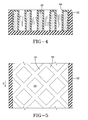
- the body 20 may be covered by an inverse U-shaped rubber crown 32, see FIGS. 3A and 4. If employed, this rubber crown 32 protects the composite grid structure upon contact with the rolling deflated tire 14, dampens impacts, and improves comfort by cushioning shocks.
- the female mold may be formed from a rubber material.
- the rubber mold has a toroidal shape, with an internal diameter equivalent to the rim platform diameter.
- the mold grooves may face outward of the toroidal configuration requiring external winding of the reinforcement composite or the mold grooves may face inward of the toroidal configuration requiring internal winding of the reinforcement composite.
- the elastomeric material must be of sufficient flexibility to permit the formed grid to be released from the mold after curing.
- the mold grooves face inward, and after curing, the female mold becomes the rubber crown 32 of the support ring 10.
- the mold may only be partially cured prior to winding of the reinforcement composite.
- Partial curing of the rubber mold will ensure adequate support stiffness for winding of the reinforcement composite.
- the mold and composite are then cured together, forming a solid structure.
- the resultant support ring 10 has the rubber crown extending into the depth of the ring, protecting each rib 22, 24 of the ring 10, as seen in FIG. 3B.
- the support ring 10 is inserted on the rim 12 during assembly of the run-flat tire system. Due to the tight clearance between the inner diameter of the support ring 10 and the tire rim platform 16, a lubricant may be applied to either the inner diameter of the support ring 10 or the tire rim platform 16. To reduce any possible rim contamination due to the lubricant, it is preferred to lubricate the support ring 10.
- each ring half is provided with a continuous solid rib on each edge.
- a room temperature self-curing adhesive is applied to each solid rib at the edges of the ring halves.
- Protective clamps may be applied at each connection point along the lateral edges of the ring. These clamps may also be glued to keep the clamps in place.
- the ring halves may be bolted together at the edge ribs by means of traditional nuts and bolts.
- FIG. 5 illustrates another embodiment of the grid for the support ring 10.
- the ribs 34, 36 forming the grid are inclined at equal but opposite angles, forming a plurality of diamond shaped openings 38.
- the ribs 34, 36 are illustrated inclined at 45° relative to a circumferential direction D of the ring 10.
- the ribs 34, 36 may be inclined at any angle between 30° and 60° relative to the circumferential direction D of the ring 10.
- the rib inclination angle and spacing between adjacent ribs 34, 36 are dictated by the desired weight and strength characteristics desired for the support ring 10.
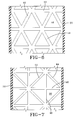
- the ribs 40, 42, 44, 48 may also form triangular shaped openings 46, 50 see FIGS. 6 and 7.
- the grid is formed from a series of laterally extending ribs 40, and two sets of circumferentially inclined ribs 42, 44.
- the inclined rib sets 42, 44 are inclined at equal and opposite angles from each other.
- the ribs 42, 44 are illustrated as being inclined at 60° relative to the lateral ribs, but may be inclined at any angle between 30° and 75° relative to the lateral ribs 40.
- the grid configuration of FIG. 7 is similar to that of FIG. 6.
- the grid includes a set of circumferentially extending ribs 48, inclined at 90° relative to the laterally extending ribs 40.
- the circumferentially extending ribs 48 divide the isosceles triangular cells 46 of FIG. 6 into right-angled triangle cells 50.
- the configurations employing inclined rib sets provide the greater durability for run-flat applications.
- the inclined ribs avoid any sudden contact of the entire rib width as the tire 14 travels through its rotation.
- the inclined rib configuration for the support ring 10 ensures that a relatively constant volume of ribs is in contact with the rotating deflated tire at any one time.
- the composite grid support ring 10 intended to be mounted on an asymmetric rim 12, can be used on any type of pneumatic tire intended to be used in low pressure operation, such as a self-supporting tire.
- the support ring 10 is also not limited to use with tires designed solely for low pressure operation.
- the composite grid support ring 10 is lighter than a solid metallic or solid rubber insert. Since the support ring 10 is mostly hollow, heat dissipation is much more efficient than with a solid structure. Additionally, the grid structure 20 of the rubber-covered ring 10 reduces heat accumulation in comparison to a continuous circumferential metallic insert or solid rubber insert.
Landscapes
- Engineering & Computer Science (AREA)
- Mechanical Engineering (AREA)
- Tires In General (AREA)
Abstract
Description
- The present invention is directed towards a support ring to support the underside of a tire during reduced pressure operation. More specifically, disclosed is a composite grid reinforced rim insert designed to support a tire during reduced pressure operation.
- Numerous devices have already been designed to enable tires to continue to operate during reduced pressure conditions. One typical device is an elastomer ring mounted on the rim of a wheel inside the pneumatic tire fitted to the wheel. The elastomer ring has an annular base clamped onto the tire rim, holding the beads of the tire pressed against rim flanges. The ring has a radially-projecting annular portion extending towards the tire tread which, in the event of a reduced tire pressure, acts to support the underside of the tread, enabling the vehicle operator to continue driving without having to stop immediately to change the tire. US-A-6,076,578 discloses one such device.
- Another type of device is shown in US-A-6,564,842. The insert is mounted on the tire rim and is not required to contact the tire beads; instead the tire beads are designed to lock into the tire rim during reduced pressure operation. Again, the radially outer surface of the insert supports the underside of the tire during reduced pressure operation.
- The goal of both types of rim inserts is to provide the tire with support and enable the vehicle operator to continue to operate the vehicle for at least another 50 km at a safe operating speed. This continued operation gives the operator time to reach a safe location where the tire can be changed.
- Several concerns for such devices has been the weight added to the vehicle by the presence of four rim inserts increasing the overall weight of the tire/wheel system, and the durability of the rim insert. Ideally, the rim insert has an optimized reduced weight and an optimized increased durability to withstand the forces to which it will be subjected during run-flat operation.
- The present invention is directed towards a rim insert to support the underside of a tire tread during run-flat operation. The rim insert, or support ring, is designed for optimized reduced weight, while achieving high durability characteristics.
- Disclosed is a run flat safety support ring intended to be mounted on a wheel rim inside a tire equipping a vehicle for supporting the tire tread in case of loss of inflation pressure. The support ring has a generally cylindrical crown intended to come in contact with the interior of the tire tread in the event of the loss of inflation pressure, but has a clearance from the tire tread interior at normal pressure. The ring also has an annular body located radially inward of the crown, the annular body comprising a grid of continuous reinforcement composite.
- In one aspect of the invention, the continuous reinforcement composite forming the grid of the annular body is selected from the group consisting of epoxy pre-impregnated fibers and metal matrix composites. Alternatively, the continuous reinforcement composite may be a glass fiber reinforced plastic or a carbon fiber reinforced plastic.
- In another aspect of the invention, the grid of continuous reinforcement composite forming the annular body is an open cellular grid formed by a plurality of intersecting ribs. The open cellular grid forms a plurality of polygonal shaped cells.
- In another aspect of the invention, the intersecting ribs forming the open cellular grid of the annular body are a plurality of ribs inclined at angles of 90° or less relative to the circumferential direction of the ring. In another aspect, the ribs may be inclined at angles of 30° to 60° relative to the circumferential direction of the ring. In another aspect, there are a combination of laterally extending ribs and at least one set of circumferentially extending ribs.
- In another aspect of the invention, to improve ride comfort, the radially outer surface of the support ring may be provided with a rubber crown. Preferably, the support ring is provided with a U-shaped rubber crown that envelopes the sides of the support ring.
- The invention will be described by way of example and with reference to the accompanying drawings in which:
- FIG. 1 is an axial cross sectional view of a tire/wheel system, including a rim insert ring;
- FIG. 2 is a circumferential cross sectional view of the rim insert ring;
- FIG. 3 is a view of the ring;
- FIG. 3A is an isoview of the insert ring of FIG. 3;
- FIG. 3B is an alternative construction of the support ring of FIG. 3;
- FIG. 4 is a cross sectional view of the rim insert ring; and
- FIGS. 5-7 are various embodiments of the rim insert ring.
- FIGS. 1 and 2 illustrate a
support ring 10 in accordance with the present invention. Thering 10 is mounted around atire rim 12, and inside the cavity of acorresponding tire 14. Therim 12 is asymmetrical, and has aplatform 16 on which the support ring is mounted. Thesupport ring 10 is generally cylindrical and has acrown 18 and anannular body 20 located radially inward of thecrown 18. Thecrown 18 is intended to come into contact with the interior of thetire 14 in the event of the loss of inflation pressure. During normal inflation pressure, as seen in FIG. 1, there is clearance between thecrown 18 and the tire inside. Theannular body 20 is a series of intersecting ribs forming a grid. - FIGS. 3 and 3A show one embodiment of the
support ring 10. Thesupport ring 10 has a series oflateral ribs 22 and a series of circumferentially extendingribs 24, forming an open cell grid. Theribs square cells 26. The relative spacing between adjacentlateral ribs 22 and the circumferentially extendingribs 24 dictates the cellular shape. The cellular shape formed by the grid can be any polygonal shape, such as triangles, rectangles, squares, trapezoids, parallelograms. - The openness of the grid provides the
support ring 10 with the desired lightweight characteristic. To provide thesupport ring 10 with the necessary strength, the grid is fabricated using continuous reinforcement composites. One group of continuous reinforcement composites is epoxy pre-impregnated fibers, such as glass fiber reinforced plastics, carbon fiber reinforced plastics, or an aluminum-fiberglass composite formed from alternating layers of fiberglass and aluminum. Another group is metal matrix composites. Metal matrix composites might better sustain fatigue damage in the high frequency impact loading to which the support ring will be subjected during run-flat operations. One form of metal matrix composites includes an aluminum/rubber composite formed of alternating layers of aluminum and rubber. A combination composite is also permissible, such as a composite formed of aluminum, fiberglass, and rubber stacking. - Manufacturing of the grid is accomplished in the following manner. A grooved female mold, laid out in the manner desired for the grid is prepared. Preferably, the mold is formed from a hard lightweight material such as polyethylene or any semi-rigid plastic. The mold has an internal diameter equivalent to the rim platform diameter. The reinforcement filaments are then wound in the mold grooves. The entire built up structure is then cured. The curing mechanism is dependent upon the reinforcement composite being employed. Basic teachings regarding forming of grids can be found in US-A-5,888,608.
- Following curing of the reinforced composite, the cured composite is removed from the mold. Should removal from the mold prove difficult, or if desired for strength reasons, the composite 28 may be left in the
mold 30; themold 30 acting as a protective wrapping for the curedcomposite 28 and being part of the support ringannular body 20. Thebody 20 may be covered by an inverseU-shaped rubber crown 32, see FIGS. 3A and 4. If employed, thisrubber crown 32 protects the composite grid structure upon contact with the rolling deflatedtire 14, dampens impacts, and improves comfort by cushioning shocks. - Alternatively, the female mold may be formed from a rubber material. The rubber mold has a toroidal shape, with an internal diameter equivalent to the rim platform diameter. The mold grooves may face outward of the toroidal configuration requiring external winding of the reinforcement composite or the mold grooves may face inward of the toroidal configuration requiring internal winding of the reinforcement composite. When the mold grooves face outward, the elastomeric material must be of sufficient flexibility to permit the formed grid to be released from the mold after curing. Preferably, the mold grooves face inward, and after curing, the female mold becomes the
rubber crown 32 of thesupport ring 10. To prevent overcuring of the elastomeric female mold, the mold may only be partially cured prior to winding of the reinforcement composite. Partial curing of the rubber mold will ensure adequate support stiffness for winding of the reinforcement composite. The mold and composite are then cured together, forming a solid structure. Theresultant support ring 10 has the rubber crown extending into the depth of the ring, protecting eachrib ring 10, as seen in FIG. 3B. - The
support ring 10 is inserted on therim 12 during assembly of the run-flat tire system. Due to the tight clearance between the inner diameter of thesupport ring 10 and thetire rim platform 16, a lubricant may be applied to either the inner diameter of thesupport ring 10 or thetire rim platform 16. To reduce any possible rim contamination due to the lubricant, it is preferred to lubricate thesupport ring 10. - Another alternative is to build the
support ring 10 in two sections. For such a construction, each ring half is provided with a continuous solid rib on each edge. Prior to placement on thetire rim 12, a room temperature self-curing adhesive is applied to each solid rib at the edges of the ring halves. Protective clamps may be applied at each connection point along the lateral edges of the ring. These clamps may also be glued to keep the clamps in place. Alternatively, the ring halves may be bolted together at the edge ribs by means of traditional nuts and bolts. - FIG. 5 illustrates another embodiment of the grid for the
support ring 10. Theribs openings 38. Theribs ring 10. Theribs ring 10. The rib inclination angle and spacing betweenadjacent ribs support ring 10. - The
ribs openings ribs 40, and two sets of circumferentiallyinclined ribs ribs lateral ribs 40. - The grid configuration of FIG. 7 is similar to that of FIG. 6. The grid includes a set of circumferentially extending
ribs 48, inclined at 90° relative to the laterally extendingribs 40. Thecircumferentially extending ribs 48 divide the isoscelestriangular cells 46 of FIG. 6 into right-angled triangle cells 50. - The configurations employing inclined rib sets, such as those shown in FIGS 5-7, provide the greater durability for run-flat applications. The inclined ribs avoid any sudden contact of the entire rib width as the
tire 14 travels through its rotation. The inclined rib configuration for thesupport ring 10 ensures that a relatively constant volume of ribs is in contact with the rotating deflated tire at any one time. - The composite
grid support ring 10, intended to be mounted on anasymmetric rim 12, can be used on any type of pneumatic tire intended to be used in low pressure operation, such as a self-supporting tire. Thesupport ring 10 is also not limited to use with tires designed solely for low pressure operation. - In comparison to inserts used with conventional pneumatic tires, the composite
grid support ring 10 is lighter than a solid metallic or solid rubber insert. Since thesupport ring 10 is mostly hollow, heat dissipation is much more efficient than with a solid structure. Additionally, thegrid structure 20 of the rubber-coveredring 10 reduces heat accumulation in comparison to a continuous circumferential metallic insert or solid rubber insert. - Additionally, while actual dimensions of the
ring 10 are dependent upon the actual size of thetire 14 and rim 12 to be employed in combination with thesupport ring 10, it should be appreciated that the wider thesupport ring 10, the greater the support being provided to thetire 14. Under underinflated operating conditions, a wider support improves run flat handling by yielding a wider contact footprint, and this increased contact area provides for a larger load carrying capacity of the run-flat tire assembly.
Claims (10)
- A run flat safety support ring intended to be mounted on a wheel rim (12) inside a tire (10) equipping a vehicle for supporting the tire tread in case of loss of inflation pressure, comprising
a generally cylindrical crown (18) intended to come in contact with the interior of the tire tread in the event of the loss of inflation pressure, and leaving a clearance from the tire tread interior at normal pressure;
an annular body (20) located radially inward of the crown (18),
the support ring (10) being characterized by the annular body (20) comprising a grid of continuous reinforcement composite. - A support ring in accordance with claim 1, wherein the continuous reinforcement composite is selected from the group consisting of epoxy pre-impregnated fibers, metal matrix composites, glass fiber reinforced plastic, a carbon fiber reinforced plastic, and an aluminum/fiberglass composite.
- A support ring in accordance with claim 1 or 2, wherein the grid is an open cellular grid formed by a plurality of intersecting ribs (34, 36).
- A support ring in accordance with claim 3, wherein the intersecting ribs comprise a plurality of ribs intersecting at angles of 90° or less relative to the circumferential direction of the ring (10).
- A support ring in accordance with claim 3, wherein the intersecting ribs comprise a plurality of ribs intersecting at angles of 30° to 60° relative to the circumferential direction of the ring (10).
- A support ring in accordance with claim 3, wherein the intersecting ribs comprise laterally extending ribs (22) and at least one set of circumferentially extending ribs (24), the circumferentially extending ribs (24) being inclined at an angle of 90° or less relative to the circumferential direction of the support ring (10).
- A support ring in accordance with claim 3, wherein the intersecting ribs form polygonal shaped cells.
- A support ring in accordance with at least one of the previous claims, wherein the ring (10) further comprises a rubber crown (32).
- A support ring in accordance with claim 8, the ring (10) further comprising a U-shaped rubber crown.
- A support ring in accordance with at least one of the previous claims, the ring further comprising a rubber crown (32) wherein the grid of continuous reinforcement composite is encased in rubber on all sides except the radially innermost side of the support ring (10).
Applications Claiming Priority (1)
| Application Number | Priority Date | Filing Date | Title |
|---|---|---|---|
| US10/995,860 US7451792B2 (en) | 2004-11-23 | 2004-11-23 | Tire support ring |
Publications (1)
| Publication Number | Publication Date |
|---|---|
| EP1659003A1 true EP1659003A1 (en) | 2006-05-24 |
Family
ID=35520522
Family Applications (1)
| Application Number | Title | Priority Date | Filing Date |
|---|---|---|---|
| EP05110747A Withdrawn EP1659003A1 (en) | 2004-11-23 | 2005-11-15 | Tire support ring |
Country Status (2)
| Country | Link |
|---|---|
| US (1) | US7451792B2 (en) |
| EP (1) | EP1659003A1 (en) |
Cited By (1)
| Publication number | Priority date | Publication date | Assignee | Title |
|---|---|---|---|---|
| CN115626006A (en) * | 2022-10-28 | 2023-01-20 | 宁波轮骨科技有限公司 | Air-free explosion-proof inner tube for four-wheel vehicle |
Families Citing this family (2)
| Publication number | Priority date | Publication date | Assignee | Title |
|---|---|---|---|---|
| US11542850B2 (en) * | 2020-02-24 | 2023-01-03 | Ford Global Technologies, Llc | Composite exhaust isolators with reduced absorptivity |
| US11808396B2 (en) * | 2021-07-28 | 2023-11-07 | Ford Global Technologies, Llc | High thermal tolerance flexible supports |
Citations (7)
| Publication number | Priority date | Publication date | Assignee | Title |
|---|---|---|---|---|
| US3509928A (en) * | 1967-10-18 | 1970-05-05 | Elie P Aghnides | Tubeless tire with supplemental support |
| US4573509A (en) * | 1983-06-24 | 1986-03-04 | The Goodyear Tire & Rubber Company | Run flat device |
| EP0721854A1 (en) * | 1995-01-05 | 1996-07-17 | Hutchinson | Run-flat device for vehicle and method of manufacturing the same |
| EP0836957A1 (en) * | 1996-10-16 | 1998-04-22 | Hutchinson | Run-flat device for automobile, particularly for passenger vehicles |
| US5888608A (en) | 1995-08-15 | 1999-03-30 | The Board Of Trustees Of The Leland Stanford Junior University | Composite grid/frame structures |
| US6076578A (en) | 1996-10-07 | 2000-06-20 | Hutchinson | Device enabling a motor vehicle to run on a flat tire |
| US6564842B2 (en) | 1999-06-10 | 2003-05-20 | Michelin Recherche Et Technique S.A. | Lightened safety support for tire |
Family Cites Families (10)
| Publication number | Priority date | Publication date | Assignee | Title |
|---|---|---|---|---|
| US1610238A (en) * | 1924-10-13 | 1926-12-14 | Thomas J Benson | Cushion tire |
| US3730244A (en) * | 1968-04-17 | 1973-05-01 | Grace W R & Co | Compressible vehicle tire |
| US3730214A (en) * | 1971-09-24 | 1973-05-01 | Walworth Co | Rotary valve pressure regulating system |
| US3844325A (en) * | 1972-07-31 | 1974-10-29 | V Betancourt | Dual pneumatic tire casings |
| US3982576A (en) * | 1974-08-09 | 1976-09-28 | Vector Wheel Corporation | Tire structure and method |
| US4281700A (en) * | 1979-04-26 | 1981-08-04 | W. R. Grace & Co. | Run-flat vehicle tire |
| US5685926A (en) * | 1994-01-07 | 1997-11-11 | Electrion, Inc. | Lightweight, safe and damage resistant tire having honeycomb core |
| BR0114126A (en) * | 2000-09-11 | 2003-08-26 | Dow Global Technologies Inc | Void tire gusset and manufacturing method |
| FR2814118B1 (en) * | 2000-09-21 | 2003-01-24 | Michelin Soc Tech | TREAD SUPPORT SUPPORT |
| BR0318359A (en) * | 2003-06-20 | 2006-07-25 | Michelin Rech Tech | assembly comprising a hoop and an empty rotating bracket and reinforcement for an empty rotating bracket |
-
2004
- 2004-11-23 US US10/995,860 patent/US7451792B2/en not_active Expired - Fee Related
-
2005
- 2005-11-15 EP EP05110747A patent/EP1659003A1/en not_active Withdrawn
Patent Citations (7)
| Publication number | Priority date | Publication date | Assignee | Title |
|---|---|---|---|---|
| US3509928A (en) * | 1967-10-18 | 1970-05-05 | Elie P Aghnides | Tubeless tire with supplemental support |
| US4573509A (en) * | 1983-06-24 | 1986-03-04 | The Goodyear Tire & Rubber Company | Run flat device |
| EP0721854A1 (en) * | 1995-01-05 | 1996-07-17 | Hutchinson | Run-flat device for vehicle and method of manufacturing the same |
| US5888608A (en) | 1995-08-15 | 1999-03-30 | The Board Of Trustees Of The Leland Stanford Junior University | Composite grid/frame structures |
| US6076578A (en) | 1996-10-07 | 2000-06-20 | Hutchinson | Device enabling a motor vehicle to run on a flat tire |
| EP0836957A1 (en) * | 1996-10-16 | 1998-04-22 | Hutchinson | Run-flat device for automobile, particularly for passenger vehicles |
| US6564842B2 (en) | 1999-06-10 | 2003-05-20 | Michelin Recherche Et Technique S.A. | Lightened safety support for tire |
Cited By (1)
| Publication number | Priority date | Publication date | Assignee | Title |
|---|---|---|---|---|
| CN115626006A (en) * | 2022-10-28 | 2023-01-20 | 宁波轮骨科技有限公司 | Air-free explosion-proof inner tube for four-wheel vehicle |
Also Published As
| Publication number | Publication date |
|---|---|
| US7451792B2 (en) | 2008-11-18 |
| US20060108037A1 (en) | 2006-05-25 |
Similar Documents
| Publication | Publication Date | Title |
|---|---|---|
| US7523773B2 (en) | Non-pneumatic wheel | |
| EP3378676B1 (en) | Tire and wheel assembly having a non-pneumatic support structure | |
| EP2386430B1 (en) | Tire comprising springs and method of manufacturing a tire | |
| CN104884270B (en) | Tire/wheel assembly and tread rings | |
| KR101301578B1 (en) | Non-pneumatic tire | |
| EP0452628A2 (en) | Non-pneumatic tire wheel | |
| EP1225063A2 (en) | Compliant rim and wheel assembly | |
| CN102825978A (en) | System for non-pneumatic support of a vehicle | |
| CN111386201A (en) | Pneumatic tire for vehicle with reinforcing structure in internal annular cavity | |
| US20170305207A1 (en) | Lightweight tire | |
| US20040173298A1 (en) | Safety support for vehicle tires | |
| US4773461A (en) | Run-flat insert for a tire and rim assembly | |
| US5685926A (en) | Lightweight, safe and damage resistant tire having honeycomb core | |
| US5186771A (en) | Ring device for running with a flat tire | |
| US6401773B1 (en) | Puncture-compensating tire | |
| JP2003237314A (en) | Underlay structure to strengthen the crown | |
| US8397778B2 (en) | Flat-running device for a motor vehicle and mounted assembly incorporating it | |
| US7451792B2 (en) | Tire support ring | |
| EP4015242B1 (en) | Non-pneumatic tire and rim assembly | |
| KR20220077876A (en) | System for manufacturing a support structure | |
| KR102613768B1 (en) | Wheel for a support structure | |
| WO2002043974A1 (en) | Run flat pneumatic tire and a variable thickness band element therefor | |
| KR102823277B1 (en) | A nonpneumatic tire having spokes with cross members | |
| KR102646626B1 (en) | Non-pneumatic tire | |
| EP3808572B1 (en) | Non-pneumatic tire |
Legal Events
| Date | Code | Title | Description |
|---|---|---|---|
| PUAI | Public reference made under article 153(3) epc to a published international application that has entered the european phase |
Free format text: ORIGINAL CODE: 0009012 |
|
| AK | Designated contracting states |
Kind code of ref document: A1 Designated state(s): AT BE BG CH CY CZ DE DK EE ES FI FR GB GR HU IE IS IT LI LT LU LV MC NL PL PT RO SE SI SK TR |
|
| AX | Request for extension of the european patent |
Extension state: AL BA HR MK YU |
|
| 17P | Request for examination filed |
Effective date: 20061124 |
|
| 17Q | First examination report despatched |
Effective date: 20061228 |
|
| AKX | Designation fees paid |
Designated state(s): DE FR GB IT |
|
| STAA | Information on the status of an ep patent application or granted ep patent |
Free format text: STATUS: THE APPLICATION IS DEEMED TO BE WITHDRAWN |
|
| 18D | Application deemed to be withdrawn |
Effective date: 20090603 |