EP1658918A2 - Method to braze a stator clip to a stator bar and clamp used in this method - Google Patents
Method to braze a stator clip to a stator bar and clamp used in this method Download PDFInfo
- Publication number
- EP1658918A2 EP1658918A2 EP05257110A EP05257110A EP1658918A2 EP 1658918 A2 EP1658918 A2 EP 1658918A2 EP 05257110 A EP05257110 A EP 05257110A EP 05257110 A EP05257110 A EP 05257110A EP 1658918 A2 EP1658918 A2 EP 1658918A2
- Authority
- EP
- European Patent Office
- Prior art keywords
- clip
- cover
- clamp
- stator
- bar
- Prior art date
- Legal status (The legal status is an assumption and is not a legal conclusion. Google has not performed a legal analysis and makes no representation as to the accuracy of the status listed.)
- Withdrawn
Links
Images

Classifications
-
- B—PERFORMING OPERATIONS; TRANSPORTING
- B23—MACHINE TOOLS; METAL-WORKING NOT OTHERWISE PROVIDED FOR
- B23K—SOLDERING OR UNSOLDERING; WELDING; CLADDING OR PLATING BY SOLDERING OR WELDING; CUTTING BY APPLYING HEAT LOCALLY, e.g. FLAME CUTTING; WORKING BY LASER BEAM
- B23K3/00—Tools, devices or special appurtenances for soldering, e.g. brazing, or unsoldering, not specially adapted for particular methods
- B23K3/08—Auxiliary devices therefor
- B23K3/087—Soldering or brazing jigs, fixtures or clamping means
-
- B—PERFORMING OPERATIONS; TRANSPORTING
- B23—MACHINE TOOLS; METAL-WORKING NOT OTHERWISE PROVIDED FOR
- B23K—SOLDERING OR UNSOLDERING; WELDING; CLADDING OR PLATING BY SOLDERING OR WELDING; CUTTING BY APPLYING HEAT LOCALLY, e.g. FLAME CUTTING; WORKING BY LASER BEAM
- B23K37/00—Auxiliary devices or processes, not specially adapted for a procedure covered by only one of the other main groups of this subclass
- B23K37/04—Auxiliary devices or processes, not specially adapted for a procedure covered by only one of the other main groups of this subclass for holding or positioning work
- B23K37/0426—Fixtures for other work
- B23K37/0435—Clamps
-
- B—PERFORMING OPERATIONS; TRANSPORTING
- B25—HAND TOOLS; PORTABLE POWER-DRIVEN TOOLS; MANIPULATORS
- B25B—TOOLS OR BENCH DEVICES NOT OTHERWISE PROVIDED FOR, FOR FASTENING, CONNECTING, DISENGAGING, OR HOLDING
- B25B5/00—Clamps
- B25B5/06—Arrangements for positively actuating jaws
- B25B5/10—Arrangements for positively actuating jaws using screws
-
- H—ELECTRICITY
- H02—GENERATION; CONVERSION OR DISTRIBUTION OF ELECTRIC POWER
- H02K—DYNAMO-ELECTRIC MACHINES
- H02K15/00—Processes or apparatus specially adapted for manufacturing, assembling, maintaining or repairing of dynamo-electric machines
- H02K15/30—Manufacture of winding connections
- H02K15/33—Connecting winding sections; Forming leads; Connecting leads to terminals
- H02K15/35—Form-wound windings
- H02K15/38—Manufacturing or repairing cooling fluid boxes, e.g. ensuring both electrical and fluid connection of terminals of fluid cooled windings
-
- H—ELECTRICITY
- H02—GENERATION; CONVERSION OR DISTRIBUTION OF ELECTRIC POWER
- H02K—DYNAMO-ELECTRIC MACHINES
- H02K3/00—Details of windings
- H02K3/46—Fastening of windings on the stator or rotor structure
- H02K3/50—Fastening of winding heads, equalising connectors, or connections thereto
- H02K3/505—Fastening of winding heads, equalising connectors, or connections thereto for large machine windings, e.g. bar windings
-
- Y—GENERAL TAGGING OF NEW TECHNOLOGICAL DEVELOPMENTS; GENERAL TAGGING OF CROSS-SECTIONAL TECHNOLOGIES SPANNING OVER SEVERAL SECTIONS OF THE IPC; TECHNICAL SUBJECTS COVERED BY FORMER USPC CROSS-REFERENCE ART COLLECTIONS [XRACs] AND DIGESTS
- Y10—TECHNICAL SUBJECTS COVERED BY FORMER USPC
- Y10T—TECHNICAL SUBJECTS COVERED BY FORMER US CLASSIFICATION
- Y10T29/00—Metal working
- Y10T29/49—Method of mechanical manufacture
- Y10T29/49002—Electrical device making
- Y10T29/49009—Dynamoelectric machine
-
- Y—GENERAL TAGGING OF NEW TECHNOLOGICAL DEVELOPMENTS; GENERAL TAGGING OF CROSS-SECTIONAL TECHNOLOGIES SPANNING OVER SEVERAL SECTIONS OF THE IPC; TECHNICAL SUBJECTS COVERED BY FORMER USPC CROSS-REFERENCE ART COLLECTIONS [XRACs] AND DIGESTS
- Y10—TECHNICAL SUBJECTS COVERED BY FORMER USPC
- Y10T—TECHNICAL SUBJECTS COVERED BY FORMER US CLASSIFICATION
- Y10T29/00—Metal working
- Y10T29/49—Method of mechanical manufacture
- Y10T29/49002—Electrical device making
- Y10T29/49009—Dynamoelectric machine
- Y10T29/49012—Rotor
-
- Y—GENERAL TAGGING OF NEW TECHNOLOGICAL DEVELOPMENTS; GENERAL TAGGING OF CROSS-SECTIONAL TECHNOLOGIES SPANNING OVER SEVERAL SECTIONS OF THE IPC; TECHNICAL SUBJECTS COVERED BY FORMER USPC CROSS-REFERENCE ART COLLECTIONS [XRACs] AND DIGESTS
- Y10—TECHNICAL SUBJECTS COVERED BY FORMER USPC
- Y10T—TECHNICAL SUBJECTS COVERED BY FORMER US CLASSIFICATION
- Y10T29/00—Metal working
- Y10T29/53—Means to assemble or disassemble
- Y10T29/5313—Means to assemble electrical device
- Y10T29/53143—Motor or generator
-
- Y—GENERAL TAGGING OF NEW TECHNOLOGICAL DEVELOPMENTS; GENERAL TAGGING OF CROSS-SECTIONAL TECHNOLOGIES SPANNING OVER SEVERAL SECTIONS OF THE IPC; TECHNICAL SUBJECTS COVERED BY FORMER USPC CROSS-REFERENCE ART COLLECTIONS [XRACs] AND DIGESTS
- Y10—TECHNICAL SUBJECTS COVERED BY FORMER USPC
- Y10T—TECHNICAL SUBJECTS COVERED BY FORMER US CLASSIFICATION
- Y10T29/00—Metal working
- Y10T29/53—Means to assemble or disassemble
- Y10T29/5313—Means to assemble electrical device
- Y10T29/53265—Means to assemble electrical device with work-holder for assembly
-
- Y—GENERAL TAGGING OF NEW TECHNOLOGICAL DEVELOPMENTS; GENERAL TAGGING OF CROSS-SECTIONAL TECHNOLOGIES SPANNING OVER SEVERAL SECTIONS OF THE IPC; TECHNICAL SUBJECTS COVERED BY FORMER USPC CROSS-REFERENCE ART COLLECTIONS [XRACs] AND DIGESTS
- Y10—TECHNICAL SUBJECTS COVERED BY FORMER USPC
- Y10T—TECHNICAL SUBJECTS COVERED BY FORMER US CLASSIFICATION
- Y10T29/00—Metal working
- Y10T29/53—Means to assemble or disassemble
- Y10T29/53978—Means to assemble or disassemble including means to relatively position plural work parts
Definitions
- the present invention relates to large stator bars that are used in power and industrial generators, handling these bars before they are installed in a stator, and fitting header clips to the bars during assembly.
- Stator bars are typically large, long and heavy, e.g., 35 feet long and hundreds of pounds (lbs.).
- the bars are generally straight and extend the length of a stator. When seated in a stator, the straight sections of the stator bars form a cylindrical array around a rotor.
- the ends of the stator bars extend axially from opposite ends of the stator.
- the end portion of the stator bars extend from the stator and are curved to form end turns.
- the ends of stator bars are connected through copper or stainless steel fittings and water-cooled connections to form continuous hydraulic winding circuits.
- Each water-cooled stator bar comprises an array of small rectangular solid and hollow copper strands.
- the array of copper strands in each bar are generally arranged in a rectangular bundle.
- the hollow strands each have an internal duct for conducting coolant through the bar.
- the ends of the bars are each connected to a hydraulic header clip.
- the hydraulic header clip serves as an electrical and a cooling flow connection for the armature winding bar.
- the hydraulic header clip is a hollow connector that includes an enclosed chamber for ingress or egress of a cooling liquid, typically deionized water. At one open end, the clip encloses the ends of the copper strands of the armature winding bar.
- a braze alloy bonds the end sections of the strands to each other and to the hydraulic header clip.
- the ends of the solid and hollow strands are brazed to a hydraulic header clip fitted to the end of the stator bar. Holding the assembly of strands and header clip together during the braze process is difficult. There is a long felt need for a tool to assist in fitting the hydraulic header clip to the end of a stator bar.
- a method to attach a stator clip to a stator bar comprising: placing the clip on an end of the stator bar; clamping the clip together to secure the clip to the stator bar; applying a press to the clip to hold the clip together and to secure the clip to the stator bar; after applying the press, removing the clamp; heating the clip while the press is applied and after the clamp has been removed to braze the clip to the bar, and removing the press and cooling the brazed clip.
- the invention also provides a clamp for attaching a clip to an end of a stator bar
- the clamp includes: an anchor adapted to fit into an open end of the clamp; a bracket having a first leg extending radially from the anchor and a second leg substantially perpendicular to the first leg, wherein the second leg further comprises a distal end having a pivot point; at least one alignment post on an inside surface of the second leg; a lever arm pivotably attached to the pivot point on the second leg of the bracket, the lever arm further comprising a lip on a first end of the arm and adapted to releasably engage an edge of a cover to clip, and an adjustment screw threaded through the lever arm and having a first screw end abutting an outside surface of the second leg of the bracket, wherein turning the screw pivots the lever arm and moves the lip towards or away from the cover.
- a clamp has been developed for attaching a stator bar clip to an end of a stator bar, said clamp comprising: an anchor adapted to fit into an open end of the clip; a bracket extending outside of the clip from the anchor and to a pivot point, and a lever arm pivotably attached to the pivot point of the bracket, the lever arm further comprising a lip on a first end of the arm adapted to releasably engage an edge of a cover to clip.
- FIGURE 1 illustrates a liquid-cooled stator bar arrangement for a stator in a typical liquid-cooled generator.
- a stator core 10 has stator core flanges 12 and core ribs 14.
- Stator bars 16 (also referred to as armature winding bars) pass through radially extending slots in the stator core and are capped at opposite ends by hydraulic header clips 18 fitted to the ends of the bars.
- Copper or stainless steel fittings 20 connect adjacent ends of the stator bar pairs to form the complete armature coil.
- Inlet hoses 22 connect an inlet clip 18 to an inlet coolant header 24.
- Outlet hoses 26 connect an outlet clip 18 to an outlet coolant header 28.
- Each stator bar forms a half an armature coil.
- a pair of stator bars linked at their opposite ends form a complete armature coil.
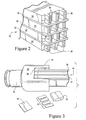
- FIGURE 2 is a perspective end view of an stator bar 16 without a hydraulic header clip.
- the bar is a rectangular array of solid 34 and hollow 36 copper strands.
- FIGURE 3 is a perspective view of the end of an armature winding bar 16 inserted in a clip 18 with braze strips 30 and a braze sheet 50.
- a clip cover 32 is shown to the side of the clip 18.
- the braze strips 30 are interleaved between tiered rows of solid the copper strands 34 and rows of hollow strands 36 of the bar 16.
- braze strips are inserted between the strands 34, 36.
- the braze sheets 50 and clip 32 are assembled in the clip 18.
- the pre-braze positioned braze alloy strips extend beyond the ends of the short solid strands.
- the height of the alloy pre-positioned before brazing is selected so that the braze alloy will entirely melt during the braze process and not flow into the open ends of the extended hollow strands.
- the hydraulic header clip 18 (also referred to as a stator bar clip) is formed of an electrically conductive material, such as copper.
- the clip 18 is hollow and includes a rectangular collar 38 that slides over the outer side surfaces of the end of the armature winding bar 16.
- a rectangular slot 39 in the collar receives the end of the armature winding bar and interleaved strips 30 of the braze alloy.
- a clip cover 32 fits into the matching rectangular slot 39 in the side of the collar 38.
- Sheets 50 of braze alloy are arranged around the inside surface of the collar and surrounding the end of the bar.
- At the other end of the clip 18 is a cylindrical coupling end 40 that is configured to connect to the coolant circuit.
- the stator bar is held in a vertical position. When the stator bar is vertical the planer end of the bar is horizontal. An end clip 18 is fitted to the end of the stator bar and braze material 30, 50 is placed between the clip and bar.
- Melted braze alloy forms a pool over the solid strand ends of the stator bar.
- the braze alloy material 30, 50 may be a rolled, essentially phosphorous-free, silver based braze alloy.
- the braze alloy forms a braze alloy isolation coating over the end of the armature bar (but not the end of the hollow strands). The isolation layer shields the solid strand ends and the joints from the coolant passage in the clip.
- the braze alloy also bonds the clip to the strands and the strand ends to each other.
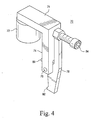
- FIGURE 4 is a perspective view of an end clip clamp 70 that holds the assembly of strands, strips, sheets and clip together during the braze operation.
- the clamp 70 is a tool attached to the clip 18 before brazing and removed thereafter.
- the clamp includes an anchor 72 that fits into the open hose coupling end 40 of the clip.
- the anchor may be a cylindrical or half-moon stub that fits snugly in the end 40 (Fig. 3) of the clip.
- the anchor steadies the clamp 70 with respect clip 18.
- An L-shaped bracket 74 extends radially from the base of the anchor and beyond the width of the clip, where the bracket turns and extends a portion of the length of the clip.
- a pivot pin 76 in the end of the bracket 74 attaches to a lever arm 78.
- the end of the bracket includes a slot to receive the lever arm.
- the lever arm fits in the slot and between two fingers at the end of the bracket.
- On an inside surface of the bracket near the pivot pin are a pair of alignment screws (one shown) 80 that rest against the clip. These screws separate the clamp (and particularly the bracket) from the sidewall of the clamp.
- the lever arm has a lip 82 to latch onto a far edge of the cover 32 when seated in the slot 39 of the clip. The lip of the lever arm and clamp 70 hold the cover in the clip when the assembly of clip, cover and end of stator are brazed.
- the lever arm 78 pivots to swing the lip 82 outward and allow a technician to fit the clamp on the clip 18.
- the lip is pivoted forward to engage the edge of the of the cover and hold the cover in the clip.
- a jack screw 84 allows the technician to move the lip under the edge of the cover and tightly fit the cover in the slot 39 of the clip.
- the inside surface of the lip 82 (which engages the cover) is slanted to move the clip cover upward into the slot as the lever arm pivots.
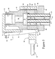
- FIGURE 5 is a cross-sectional end view of the clamp 70 attached to a hydraulic header clip 18, while a ram 54 presses the clip cover 34 into the clip.
- a brazing device e.g., a brazing hood.
- the hood may have an associated cylindrical ram 54 that compresses the clip cover 32 into the header clip 18 during the braze process.
- the ram 54 presses the clip cover 32 into the collar 38 to compress together the ends of the strands 34, 36 and interleaved braze strips.
- the ram 54 presses the cover into the collar and before heating, the clamp 70 is removed from the clip. After the clamp is removed, the clip and bar assembly is heated to liquefy the braze material.
- the induction heating coil 66 heats the assembly of the clip, strand and braze strips 30 and sheets 50.
- the heating coil 66 heats the clip and end of the stator bar to braze them together.
- a heating mass 56 may be placed between the end of the ram 54 and the clip cover 32.
- the heating mass 56 may be formed a thermally conductive material, such as steel or copper.
- the heating mass 56 is heated by the heating coil 66 and conducts heat to the clip cover.
- the heating mass may have an inverted "C" shape in cross-section to fit the end of the ram and fit into the "C" shaped heating coil 66.
- the heating mass slides between the legs of the heating coil without touching the coil.
- the heating mass may also have a slot on its front face to receive the lever arm 78 of the clamp 70. The heating mass ensures that heat is applied to the clip cover during brazing.
- Mica may be used for spacers 67 separating the coil from the clip and the heating mass 56 from the clip cover.
- the mica spacer between the coil and clip may be 0.060 inches and the spacer between the mass 56 and clip cover may be 0.030 inches.
- a thermal mass spacer 68 may be used to insulate the shaft 54 of the ram from the heating mass 56.
- a heat sink clamp 69 is attached to the stator bar below the heated end of the bar.
- the heat sink cools the stator bar below the clip. By cooling the bar, liquefied braze is prevented from flowing down between the strands when the vertical bar is in the braze hood.
- the braze joint is preferably made with the stator bar in a vertical orientation.
- the vertical orientation is preferred because it aids alloy retention in the joint and permits pieces of the alloy to be more easily pre-placed on the surface of the assembly inside the hydraulic header clip, thereby providing a source of additional braze alloy and/or filler metal that will melt and flow over the bar 16 end surfaces to create a thicker layer of braze isolation layer over the ends of the solid copper strands of the bar.
Landscapes
- Engineering & Computer Science (AREA)
- Mechanical Engineering (AREA)
- Power Engineering (AREA)
- Manufacturing & Machinery (AREA)
- Physics & Mathematics (AREA)
- Optics & Photonics (AREA)
- Manufacture Of Motors, Generators (AREA)
Abstract
Description
- The present invention relates to large stator bars that are used in power and industrial generators, handling these bars before they are installed in a stator, and fitting header clips to the bars during assembly.
- Stator bars are typically large, long and heavy, e.g., 35 feet long and hundreds of pounds (lbs.). The bars are generally straight and extend the length of a stator. When seated in a stator, the straight sections of the stator bars form a cylindrical array around a rotor. The ends of the stator bars extend axially from opposite ends of the stator. The end portion of the stator bars extend from the stator and are curved to form end turns. The ends of stator bars are connected through copper or stainless steel fittings and water-cooled connections to form continuous hydraulic winding circuits.
- Each water-cooled stator bar comprises an array of small rectangular solid and hollow copper strands. The array of copper strands in each bar are generally arranged in a rectangular bundle. The hollow strands each have an internal duct for conducting coolant through the bar. The ends of the bars are each connected to a hydraulic header clip.
- The hydraulic header clip serves as an electrical and a cooling flow connection for the armature winding bar. The hydraulic header clip is a hollow connector that includes an enclosed chamber for ingress or egress of a cooling liquid, typically deionized water. At one open end, the clip encloses the ends of the copper strands of the armature winding bar.
- A braze alloy bonds the end sections of the strands to each other and to the hydraulic header clip. The ends of the solid and hollow strands are brazed to a hydraulic header clip fitted to the end of the stator bar. Holding the assembly of strands and header clip together during the braze process is difficult. There is a long felt need for a tool to assist in fitting the hydraulic header clip to the end of a stator bar.
- According to the present invention, there is provided a method to attach a stator clip to a stator bar comprising: placing the clip on an end of the stator bar; clamping the clip together to secure the clip to the stator bar; applying a press to the clip to hold the clip together and to secure the clip to the stator bar; after applying the press, removing the clamp; heating the clip while the press is applied and after the clamp has been removed to braze the clip to the bar, and removing the press and cooling the brazed clip.
- The invention also provides a clamp for attaching a clip to an end of a stator bar, the clamp includes: an anchor adapted to fit into an open end of the clamp; a bracket having a first leg extending radially from the anchor and a second leg substantially perpendicular to the first leg, wherein the second leg further comprises a distal end having a pivot point; at least one alignment post on an inside surface of the second leg; a lever arm pivotably attached to the pivot point on the second leg of the bracket, the lever arm further comprising a lip on a first end of the arm and adapted to releasably engage an edge of a cover to clip, and an adjustment screw threaded through the lever arm and having a first screw end abutting an outside surface of the second leg of the bracket, wherein turning the screw pivots the lever arm and moves the lip towards or away from the cover.
- A clamp has been developed for attaching a stator bar clip to an end of a stator bar, said clamp comprising: an anchor adapted to fit into an open end of the clip; a bracket extending outside of the clip from the anchor and to a pivot point, and a lever arm pivotably attached to the pivot point of the bracket, the lever arm further comprising a lip on a first end of the arm adapted to releasably engage an edge of a cover to clip.
- Embodiments of the invention will now be described, by way of the example, with reference to the accompanying drawings, in which:
- FIGURE 1 is a schematic illustration of a liquid-cooled stator winding arrangement illustrating the stator, stator bars and hydraulic header clips coupled to inlet and outlet coolant headers.
- FIGURE 2 is a perspective view of the end of an armature winding bar showing the tiered rows of hollow and solid strands, and interleaving sheets of braze material.
- FIGURE 3 is a perspective exploded view of the end of an armature winding bar inserted into a hydraulic header clip, with braze material and a clip cover shown to the side of the clip.
- FIGURE 4 is a perspective view of a clamp for holding together the winding bar and end clip assembly during brazing.
- FIGURE 5 is an end view of the strands of an armature winding bar within a hydraulic header end clip with a ram clamping the cover to the clip and a heat sink attached to the bar.
- FIGURE 1 illustrates a liquid-cooled stator bar arrangement for a stator in a typical liquid-cooled generator. A
stator core 10 hasstator core flanges 12 andcore ribs 14. Stator bars 16 (also referred to as armature winding bars) pass through radially extending slots in the stator core and are capped at opposite ends byhydraulic header clips 18 fitted to the ends of the bars. Copper orstainless steel fittings 20 connect adjacent ends of the stator bar pairs to form the complete armature coil.Inlet hoses 22 connect aninlet clip 18 to aninlet coolant header 24.Outlet hoses 26 connect anoutlet clip 18 to anoutlet coolant header 28. Each stator bar forms a half an armature coil. A pair of stator bars linked at their opposite ends form a complete armature coil. - FIGURE 2 is a perspective end view of an
stator bar 16 without a hydraulic header clip. The bar is a rectangular array of solid 34 and hollow 36 copper strands. FIGURE 3 is a perspective view of the end of anarmature winding bar 16 inserted in aclip 18 withbraze strips 30 and abraze sheet 50. Aclip cover 32 is shown to the side of theclip 18. In Figure 2, thebraze strips 30 are interleaved between tiered rows of solid thecopper strands 34 and rows ofhollow strands 36 of thebar 16. Just prior to brazing and at the end of the stator bar, braze strips are inserted between thestrands braze sheets 50 andclip 32 are assembled in theclip 18. - As shown in Figure 2, the pre-braze positioned braze alloy strips extend beyond the ends of the short solid strands. The height of the alloy pre-positioned before brazing is selected so that the braze alloy will entirely melt during the braze process and not flow into the open ends of the extended hollow strands.
- The hydraulic header clip 18 (also referred to as a stator bar clip) is formed of an electrically conductive material, such as copper. The
clip 18 is hollow and includes arectangular collar 38 that slides over the outer side surfaces of the end of thearmature winding bar 16. Arectangular slot 39 in the collar receives the end of the armature winding bar and interleavedstrips 30 of the braze alloy. Aclip cover 32 fits into the matchingrectangular slot 39 in the side of thecollar 38.Sheets 50 of braze alloy are arranged around the inside surface of the collar and surrounding the end of the bar. At the other end of theclip 18 is acylindrical coupling end 40 that is configured to connect to the coolant circuit. - During brazing, the stator bar is held in a vertical position. When the stator bar is vertical the planer end of the bar is horizontal. An
end clip 18 is fitted to the end of the stator bar andbraze material braze alloy material - FIGURE 4 is a perspective view of an
end clip clamp 70 that holds the assembly of strands, strips, sheets and clip together during the braze operation. Theclamp 70 is a tool attached to theclip 18 before brazing and removed thereafter. The clamp includes ananchor 72 that fits into the openhose coupling end 40 of the clip. The anchor may be a cylindrical or half-moon stub that fits snugly in the end 40 (Fig. 3) of the clip. The anchor steadies theclamp 70 withrespect clip 18. An L-shaped bracket 74 extends radially from the base of the anchor and beyond the width of the clip, where the bracket turns and extends a portion of the length of the clip. - A
pivot pin 76 in the end of thebracket 74 attaches to alever arm 78. The end of the bracket includes a slot to receive the lever arm. The lever arm fits in the slot and between two fingers at the end of the bracket. On an inside surface of the bracket near the pivot pin are a pair of alignment screws (one shown) 80 that rest against the clip. These screws separate the clamp (and particularly the bracket) from the sidewall of the clamp. The lever arm has alip 82 to latch onto a far edge of thecover 32 when seated in theslot 39 of the clip. The lip of the lever arm and clamp 70 hold the cover in the clip when the assembly of clip, cover and end of stator are brazed. Thelever arm 78 pivots to swing thelip 82 outward and allow a technician to fit the clamp on theclip 18. The lip is pivoted forward to engage the edge of the of the cover and hold the cover in the clip. Ajack screw 84 allows the technician to move the lip under the edge of the cover and tightly fit the cover in theslot 39 of the clip. The inside surface of the lip 82 (which engages the cover) is slanted to move the clip cover upward into the slot as the lever arm pivots. - FIGURE 5 is a cross-sectional end view of the
clamp 70 attached to ahydraulic header clip 18, while aram 54 presses theclip cover 34 into the clip. After theclamp 70 is fitted on the clip, the stator bar, and clip assembly are placed in a brazing device, e.g., a brazing hood. The hood may have an associatedcylindrical ram 54 that compresses theclip cover 32 into theheader clip 18 during the braze process. Theram 54 presses theclip cover 32 into thecollar 38 to compress together the ends of thestrands ram 54 presses the cover into the collar and before heating, theclamp 70 is removed from the clip. After the clamp is removed, the clip and bar assembly is heated to liquefy the braze material. - During brazing, the
induction heating coil 66 heats the assembly of the clip, strand and brazestrips 30 andsheets 50. Theheating coil 66 heats the clip and end of the stator bar to braze them together. Aheating mass 56 may be placed between the end of theram 54 and theclip cover 32. Theheating mass 56 may be formed a thermally conductive material, such as steel or copper. Theheating mass 56 is heated by theheating coil 66 and conducts heat to the clip cover. The heating mass may have an inverted "C" shape in cross-section to fit the end of the ram and fit into the "C" shapedheating coil 66. The heating mass slides between the legs of the heating coil without touching the coil. The heating mass may also have a slot on its front face to receive thelever arm 78 of theclamp 70. The heating mass ensures that heat is applied to the clip cover during brazing. - Mica may be used for
spacers 67 separating the coil from the clip and theheating mass 56 from the clip cover. The mica spacer between the coil and clip may be 0.060 inches and the spacer between the mass 56 and clip cover may be 0.030 inches. Athermal mass spacer 68 may be used to insulate theshaft 54 of the ram from theheating mass 56. - A
heat sink clamp 69 is attached to the stator bar below the heated end of the bar. The heat sink cools the stator bar below the clip. By cooling the bar, liquefied braze is prevented from flowing down between the strands when the vertical bar is in the braze hood. - The braze joint is preferably made with the stator bar in a vertical orientation. The vertical orientation is preferred because it aids alloy retention in the joint and permits pieces of the alloy to be more easily pre-placed on the surface of the assembly inside the hydraulic header clip, thereby providing a source of additional braze alloy and/or filler metal that will melt and flow over the
bar 16 end surfaces to create a thicker layer of braze isolation layer over the ends of the solid copper strands of the bar.
Claims (10)
- A method to attach a stator clip (18) to a stator bar (16) comprising:placing the clip on an end of the stator bar;clamping (70) the clip together to secure the clip to the stator bar;applying a press (54) to the clip to hold the clip together and to secure the clip to the stator bar;after applying the press, removing the clamp;heating (66) the clip while the press is applied and after the clamp has been removed to braze the clip to the bar, andremoving the press and cooling the brazed clip.
- The method in claim 1 wherein the clip (18) includes a cover (32) fitting into a slot (39) in the clip and the method further comprises clamping (70) the cover and clip to hold the cover in the slot.
- The method in claim 1 wherein the clip (18) includes a cover (32) fitting into a slot (39) in the clip and the method further comprises clamping (70) the cover and clip to hold the cover in the slot and applying the press (54) to the cover.
- The method in claim 1 wherein the clamp (70) includes an anchor (72) and a latch arm (78), and wherein clamping further comprises mounting the anchor on the clip and pivoting the latch arm to secure a clip cover (32) into a slot (39) in the clip.
- The method in claim 1 wherein the clamp (70) includes a latch arm (78), and wherein clamping further comprises attaching the clamp to the clip and latching the latch arm to a clip cover (32) so as to secure the cover in a slot (39) in the clip.
- The method in claim 1 wherein the press (54) is a ram and the ram abuts against the clip while the clip is seated in a heating coil.
- A clamp (70) for attaching a stator bar clip (18) to an end of a stator bar (16), said clamp comprising:an anchor (72) adapted to fit into an open end of the clip;a bracket (74) extending outside of the clip from the anchor and to a pivot point (76), anda lever arm (78) pivotably attached to the pivot point of the bracket, the lever arm further comprising a lip (82) on a first end of the arm adapted to releasably engage an edge of a cover (39) to the clip.
- The clamp (70) in claim 7 further comprising an adjustment screw (84) threaded through the lever arm and having a first screw end abutting an outside surface of the bracket, wherein turning the screw pivots the lever arm and moves the lip towards or away from the cover.
- The clamp (70) in claim 7 further comprising at least one alignment post (80) on an inside surface of the bracket.
- The clamp in claim 7 wherein the bracket (74) comprises a first leg and a second leg at a substantially right angle to the first leg.
Applications Claiming Priority (2)
| Application Number | Priority Date | Filing Date | Title |
|---|---|---|---|
| US62893104P | 2004-11-19 | 2004-11-19 | |
| US11/143,463 US7421776B2 (en) | 2004-11-19 | 2005-06-03 | Clamp to attach a stator bar to a clip |
Publications (2)
| Publication Number | Publication Date |
|---|---|
| EP1658918A2 true EP1658918A2 (en) | 2006-05-24 |
| EP1658918A3 EP1658918A3 (en) | 2006-08-30 |
Family
ID=35840519
Family Applications (1)
| Application Number | Title | Priority Date | Filing Date |
|---|---|---|---|
| EP05257110A Withdrawn EP1658918A3 (en) | 2004-11-19 | 2005-11-17 | Method to braze a stator clip to a stator bar and clamp used in this method |
Country Status (3)
| Country | Link |
|---|---|
| US (1) | US7421776B2 (en) |
| EP (1) | EP1658918A3 (en) |
| JP (1) | JP2006149187A (en) |
Cited By (5)
| Publication number | Priority date | Publication date | Assignee | Title |
|---|---|---|---|---|
| CN103028926A (en) * | 2012-12-14 | 2013-04-10 | 北车风电有限公司 | Anti-backward-slip device of wind driven generator and use method |
| CN104966597A (en) * | 2014-12-05 | 2015-10-07 | 成都虹腾科技有限公司 | Resistance wire feeder |
| CN108581137A (en) * | 2018-06-28 | 2018-09-28 | 福建省昌辉机电有限公司 | A kind of motor stator argon welding machine |
| CN110370090A (en) * | 2019-07-08 | 2019-10-25 | 东莞长盈精密技术有限公司 | Continuous machining method for workpiece surface and clamping device |
| CN118752278A (en) * | 2024-09-05 | 2024-10-11 | 西安市康铖机械制造有限公司 | Titanium alloy high efficiency processing equipment |
Families Citing this family (6)
| Publication number | Priority date | Publication date | Assignee | Title |
|---|---|---|---|---|
| DE102012022873A1 (en) * | 2012-11-22 | 2014-05-22 | Compact Dynamics Gmbh | Method for soldering stand and cooler and stand with soldered connection to the stand carrier |
| US9839176B1 (en) * | 2014-06-25 | 2017-12-12 | Brinly-Hardy Company | Accessory mount for turf or grounds care equipment |
| CN108664747B (en) * | 2018-05-18 | 2022-04-01 | 中船黄埔文冲船舶有限公司 | Design method and device of bow anchor and anchor retaining part |
| EP3847737A4 (en) * | 2018-10-22 | 2021-11-03 | Magna International Inc. | I-SPINDLE STATOR WITH FLAT WINDING CONNECTION |
| JP7114513B2 (en) | 2019-03-11 | 2022-08-08 | 株式会社東芝 | How to connect stator windings, generators and stator winding conductors |
| CN114535883B (en) * | 2022-03-29 | 2024-05-28 | 浙江晶科能源有限公司 | Clamping claw assembly and method for clamping welding strip |
Family Cites Families (13)
| Publication number | Priority date | Publication date | Assignee | Title |
|---|---|---|---|---|
| US2755760A (en) * | 1951-09-07 | 1956-07-24 | Western Electric Co | Assembling fixture |
| US3686735A (en) * | 1966-12-13 | 1972-08-29 | Ind Products Inc | Coil transfer tool |
| US4066203A (en) | 1977-01-21 | 1978-01-03 | Mcgraw-Edison Company | Method for electrically and hydraulically connecting a water-cooled conductor |
| US4309018A (en) * | 1980-02-22 | 1982-01-05 | American Standard Inc. | Clamp-down device for use in securing a member in an inaccessible area |
| US4552345A (en) * | 1984-01-26 | 1985-11-12 | Benda Steven J | Clamp mechanism |
| US4986771A (en) | 1989-10-13 | 1991-01-22 | The Richards-Braswell Research Corporation | Clamping device |
| CH683973A5 (en) | 1991-10-30 | 1994-06-30 | Abovo Ag | PCB attachment for fitting to soldering frame |
| US5494553A (en) * | 1993-09-20 | 1996-02-27 | Colucci; William G. | Multi-purpose clamping apparatus |
| US5423473A (en) | 1994-05-09 | 1995-06-13 | Westinghouse Electric Corporation | Device for installing a header cap on a water header of a stator coil |
| US5575518A (en) | 1994-12-19 | 1996-11-19 | Payne; Douglas F. | Gripper tool for handling lumber |
| US5895035A (en) | 1997-05-19 | 1999-04-20 | Bley; C. Barton | Pipe fitting apparatus |
| DE29713944U1 (en) | 1997-08-05 | 1997-10-02 | Tünkers Maschinenbau GmbH, 40880 Ratingen | Fluid-operated knee lever clamping device |
| US6877731B1 (en) * | 2003-03-18 | 2005-04-12 | J. Marlon Corley, Sr. | Joist clamp |
-
2005
- 2005-06-03 US US11/143,463 patent/US7421776B2/en not_active Expired - Fee Related
- 2005-11-10 JP JP2005325602A patent/JP2006149187A/en not_active Withdrawn
- 2005-11-17 EP EP05257110A patent/EP1658918A3/en not_active Withdrawn
Cited By (7)
| Publication number | Priority date | Publication date | Assignee | Title |
|---|---|---|---|---|
| CN103028926A (en) * | 2012-12-14 | 2013-04-10 | 北车风电有限公司 | Anti-backward-slip device of wind driven generator and use method |
| CN103028926B (en) * | 2012-12-14 | 2015-05-06 | 北车风电有限公司 | Anti-backward-slip device of wind driven generator and use method |
| CN104966597A (en) * | 2014-12-05 | 2015-10-07 | 成都虹腾科技有限公司 | Resistance wire feeder |
| CN108581137A (en) * | 2018-06-28 | 2018-09-28 | 福建省昌辉机电有限公司 | A kind of motor stator argon welding machine |
| CN108581137B (en) * | 2018-06-28 | 2023-11-07 | 福建省昌辉机电有限公司 | Motor stator argon welding machine |
| CN110370090A (en) * | 2019-07-08 | 2019-10-25 | 东莞长盈精密技术有限公司 | Continuous machining method for workpiece surface and clamping device |
| CN118752278A (en) * | 2024-09-05 | 2024-10-11 | 西安市康铖机械制造有限公司 | Titanium alloy high efficiency processing equipment |
Also Published As
| Publication number | Publication date |
|---|---|
| US7421776B2 (en) | 2008-09-09 |
| US20060107519A1 (en) | 2006-05-25 |
| JP2006149187A (en) | 2006-06-08 |
| EP1658918A3 (en) | 2006-08-30 |
Similar Documents
| Publication | Publication Date | Title |
|---|---|---|
| US7421776B2 (en) | Clamp to attach a stator bar to a clip | |
| US7741587B2 (en) | Method for applying an isolation layer to a brazed end of a generator armature winding bar | |
| US20080296289A1 (en) | Movable heating system having fixed heating source for brazing stator bars | |
| US20070158397A1 (en) | Method for applying braze end isolation layer for generator armature winding bar | |
| CN1324928C (en) | Method and apparatus for mounting heater thermostat and temp sensitive fuse | |
| KR100305931B1 (en) | Integral connector for stator winding and half coil of stator winding | |
| US11251681B2 (en) | Fixture and method of securing parts using the same | |
| JP2002301566A (en) | Induction heating tools | |
| JP2002301566A5 (en) | ||
| US7088020B2 (en) | Apparatus and method for consolidating conductive strands of a stator coil | |
| CN1841886A (en) | Method and system for a clamp used in brazing a stator bar to a clip | |
| US20060108356A1 (en) | Braze chamber and method for applying an isolation layer to a brazed end of a generator armature winding bar | |
| US7474022B2 (en) | Liquid-cooled armature bar clip-to-strand connection and method | |
| CA2552776C (en) | Movable heating method and system having fixed heating source for brazing stator bars | |
| PL150850B1 (en) | Device for head-to-head resistance soldering | |
| JP2002001526A (en) | Soldering equipment, temperature control system, and cooling tool | |
| JP2026030403A (en) | induction heating coil | |
| KR19990028673U (en) | Coil end coupling | |
| JP2001047282A (en) | Joining clamp, joining device and joining method |
Legal Events
| Date | Code | Title | Description |
|---|---|---|---|
| PUAI | Public reference made under article 153(3) epc to a published international application that has entered the european phase |
Free format text: ORIGINAL CODE: 0009012 |
|
| AK | Designated contracting states |
Kind code of ref document: A2 Designated state(s): AT BE BG CH CY CZ DE DK EE ES FI FR GB GR HU IE IS IT LI LT LU LV MC NL PL PT RO SE SI SK TR |
|
| AX | Request for extension of the european patent |
Extension state: AL BA HR MK YU |
|
| PUAL | Search report despatched |
Free format text: ORIGINAL CODE: 0009013 |
|
| AK | Designated contracting states |
Kind code of ref document: A3 Designated state(s): AT BE BG CH CY CZ DE DK EE ES FI FR GB GR HU IE IS IT LI LT LU LV MC NL PL PT RO SE SI SK TR |
|
| AX | Request for extension of the european patent |
Extension state: AL BA HR MK YU |
|
| RIC1 | Information provided on ipc code assigned before grant |
Ipc: H02K 15/00 20060101ALI20060725BHEP Ipc: B25B 5/04 20060101ALI20060725BHEP Ipc: B23K 37/04 20060101ALI20060725BHEP Ipc: B23K 3/08 20060101AFI20060313BHEP |
|
| 17P | Request for examination filed |
Effective date: 20070228 |
|
| 17Q | First examination report despatched |
Effective date: 20070403 |
|
| AKX | Designation fees paid |
Designated state(s): GB IT |
|
| REG | Reference to a national code |
Ref country code: DE Ref legal event code: 8566 |
|
| STAA | Information on the status of an ep patent application or granted ep patent |
Free format text: STATUS: THE APPLICATION IS DEEMED TO BE WITHDRAWN |
|
| 18D | Application deemed to be withdrawn |
Effective date: 20090603 |