EP1658764A1 - Apparatus comprising a tubular cross member - Google Patents
Apparatus comprising a tubular cross member Download PDFInfo
- Publication number
- EP1658764A1 EP1658764A1 EP05110374A EP05110374A EP1658764A1 EP 1658764 A1 EP1658764 A1 EP 1658764A1 EP 05110374 A EP05110374 A EP 05110374A EP 05110374 A EP05110374 A EP 05110374A EP 1658764 A1 EP1658764 A1 EP 1658764A1
- Authority
- EP
- European Patent Office
- Prior art keywords
- bevel gear
- output
- shaft
- motor
- housing
- Prior art date
- Legal status (The legal status is an assumption and is not a legal conclusion. Google has not performed a legal analysis and makes no representation as to the accuracy of the status listed.)
- Granted
Links
- 230000002028 premature Effects 0.000 description 3
- 244000025254 Cannabis sativa Species 0.000 description 2
- 238000005452 bending Methods 0.000 description 1
- 239000012530 fluid Substances 0.000 description 1
- 239000002184 metal Substances 0.000 description 1
- 230000004048 modification Effects 0.000 description 1
- 238000012986 modification Methods 0.000 description 1
- 239000000725 suspension Substances 0.000 description 1
Images

Classifications
-
- B—PERFORMING OPERATIONS; TRANSPORTING
- B60—VEHICLES IN GENERAL
- B60K—ARRANGEMENT OR MOUNTING OF PROPULSION UNITS OR OF TRANSMISSIONS IN VEHICLES; ARRANGEMENT OR MOUNTING OF PLURAL DIVERSE PRIME-MOVERS IN VEHICLES; AUXILIARY DRIVES FOR VEHICLES; INSTRUMENTATION OR DASHBOARDS FOR VEHICLES; ARRANGEMENTS IN CONNECTION WITH COOLING, AIR INTAKE, GAS EXHAUST OR FUEL SUPPLY OF PROPULSION UNITS IN VEHICLES
- B60K7/00—Disposition of motor in, or adjacent to, traction wheel
- B60K7/0015—Disposition of motor in, or adjacent to, traction wheel the motor being hydraulic
-
- A—HUMAN NECESSITIES
- A01—AGRICULTURE; FORESTRY; ANIMAL HUSBANDRY; HUNTING; TRAPPING; FISHING
- A01D—HARVESTING; MOWING
- A01D34/00—Mowers; Mowing apparatus of harvesters
- A01D34/01—Mowers; Mowing apparatus of harvesters characterised by features relating to the type of cutting apparatus
- A01D34/412—Mowers; Mowing apparatus of harvesters characterised by features relating to the type of cutting apparatus having rotating cutters
- A01D34/63—Mowers; Mowing apparatus of harvesters characterised by features relating to the type of cutting apparatus having rotating cutters having cutters rotating about a vertical axis
- A01D34/67—Mowers; Mowing apparatus of harvesters characterised by features relating to the type of cutting apparatus having rotating cutters having cutters rotating about a vertical axis hand-guided by a walking operator
- A01D34/68—Mowers; Mowing apparatus of harvesters characterised by features relating to the type of cutting apparatus having rotating cutters having cutters rotating about a vertical axis hand-guided by a walking operator with motor driven cutters or wheels
- A01D34/6806—Driving mechanisms
-
- B—PERFORMING OPERATIONS; TRANSPORTING
- B60—VEHICLES IN GENERAL
- B60K—ARRANGEMENT OR MOUNTING OF PROPULSION UNITS OR OF TRANSMISSIONS IN VEHICLES; ARRANGEMENT OR MOUNTING OF PLURAL DIVERSE PRIME-MOVERS IN VEHICLES; AUXILIARY DRIVES FOR VEHICLES; INSTRUMENTATION OR DASHBOARDS FOR VEHICLES; ARRANGEMENTS IN CONNECTION WITH COOLING, AIR INTAKE, GAS EXHAUST OR FUEL SUPPLY OF PROPULSION UNITS IN VEHICLES
- B60K17/00—Arrangement or mounting of transmissions in vehicles
- B60K17/30—Arrangement or mounting of transmissions in vehicles the ultimate propulsive elements, e.g. ground wheels, being steerable
- B60K17/303—Arrangement or mounting of transmissions in vehicles the ultimate propulsive elements, e.g. ground wheels, being steerable with a gearwheel on the steering knuckle or kingpin axis
-
- B—PERFORMING OPERATIONS; TRANSPORTING
- B62—LAND VEHICLES FOR TRAVELLING OTHERWISE THAN ON RAILS
- B62D—MOTOR VEHICLES; TRAILERS
- B62D7/00—Steering linkage; Stub axles or their mountings
- B62D7/18—Steering knuckles; King pins
-
- B—PERFORMING OPERATIONS; TRANSPORTING
- B60—VEHICLES IN GENERAL
- B60K—ARRANGEMENT OR MOUNTING OF PROPULSION UNITS OR OF TRANSMISSIONS IN VEHICLES; ARRANGEMENT OR MOUNTING OF PLURAL DIVERSE PRIME-MOVERS IN VEHICLES; AUXILIARY DRIVES FOR VEHICLES; INSTRUMENTATION OR DASHBOARDS FOR VEHICLES; ARRANGEMENTS IN CONNECTION WITH COOLING, AIR INTAKE, GAS EXHAUST OR FUEL SUPPLY OF PROPULSION UNITS IN VEHICLES
- B60K17/00—Arrangement or mounting of transmissions in vehicles
- B60K17/04—Arrangement or mounting of transmissions in vehicles characterised by arrangement, location, or kind of gearing
- B60K17/043—Transmission unit disposed in on near the vehicle wheel, or between the differential gear unit and the wheel
-
- B—PERFORMING OPERATIONS; TRANSPORTING
- B60—VEHICLES IN GENERAL
- B60K—ARRANGEMENT OR MOUNTING OF PROPULSION UNITS OR OF TRANSMISSIONS IN VEHICLES; ARRANGEMENT OR MOUNTING OF PLURAL DIVERSE PRIME-MOVERS IN VEHICLES; AUXILIARY DRIVES FOR VEHICLES; INSTRUMENTATION OR DASHBOARDS FOR VEHICLES; ARRANGEMENTS IN CONNECTION WITH COOLING, AIR INTAKE, GAS EXHAUST OR FUEL SUPPLY OF PROPULSION UNITS IN VEHICLES
- B60K7/00—Disposition of motor in, or adjacent to, traction wheel
- B60K2007/0046—Disposition of motor in, or adjacent to, traction wheel the motor moving together with the vehicle body, i.e. moving independently from the wheel axle
-
- B—PERFORMING OPERATIONS; TRANSPORTING
- B60—VEHICLES IN GENERAL
- B60K—ARRANGEMENT OR MOUNTING OF PROPULSION UNITS OR OF TRANSMISSIONS IN VEHICLES; ARRANGEMENT OR MOUNTING OF PLURAL DIVERSE PRIME-MOVERS IN VEHICLES; AUXILIARY DRIVES FOR VEHICLES; INSTRUMENTATION OR DASHBOARDS FOR VEHICLES; ARRANGEMENTS IN CONNECTION WITH COOLING, AIR INTAKE, GAS EXHAUST OR FUEL SUPPLY OF PROPULSION UNITS IN VEHICLES
- B60K7/00—Disposition of motor in, or adjacent to, traction wheel
- B60K2007/0061—Disposition of motor in, or adjacent to, traction wheel the motor axle being parallel to the wheel axle
-
- B—PERFORMING OPERATIONS; TRANSPORTING
- B60—VEHICLES IN GENERAL
- B60L—PROPULSION OF ELECTRICALLY-PROPELLED VEHICLES; SUPPLYING ELECTRIC POWER FOR AUXILIARY EQUIPMENT OF ELECTRICALLY-PROPELLED VEHICLES; ELECTRODYNAMIC BRAKE SYSTEMS FOR VEHICLES IN GENERAL; MAGNETIC SUSPENSION OR LEVITATION FOR VEHICLES; MONITORING OPERATING VARIABLES OF ELECTRICALLY-PROPELLED VEHICLES; ELECTRIC SAFETY DEVICES FOR ELECTRICALLY-PROPELLED VEHICLES
- B60L2220/00—Electrical machine types; Structures or applications thereof
- B60L2220/40—Electrical machine applications
- B60L2220/46—Wheel motors, i.e. motor connected to only one wheel
-
- B—PERFORMING OPERATIONS; TRANSPORTING
- B60—VEHICLES IN GENERAL
- B60Y—INDEXING SCHEME RELATING TO ASPECTS CROSS-CUTTING VEHICLE TECHNOLOGY
- B60Y2200/00—Type of vehicle
- B60Y2200/20—Off-Road Vehicles
- B60Y2200/22—Agricultural vehicles
- B60Y2200/223—Ridable lawn mowers
-
- Y—GENERAL TAGGING OF NEW TECHNOLOGICAL DEVELOPMENTS; GENERAL TAGGING OF CROSS-SECTIONAL TECHNOLOGIES SPANNING OVER SEVERAL SECTIONS OF THE IPC; TECHNICAL SUBJECTS COVERED BY FORMER USPC CROSS-REFERENCE ART COLLECTIONS [XRACs] AND DIGESTS
- Y10—TECHNICAL SUBJECTS COVERED BY FORMER USPC
- Y10T—TECHNICAL SUBJECTS COVERED BY FORMER US CLASSIFICATION
- Y10T74/00—Machine element or mechanism
- Y10T74/19—Gearing
Definitions
- This invention relates generally to an apparatus comprising a tubular axle cross member.
- Fairway mowers use a fixed front axle as the primary drive, and have a steerable rear axle.
- the "primary" axle is a driven or powered axle.
- the front wheels are hydraulically powered to help the machines turn and steer on soft, wet turf, without tearing it.
- Efforts to power fairway mowers mechanically using differentials and/or over-running clutches have had only limited success.
- the rear axle of a fairway mower also may be powered.
- the rear axle may be powered by a hydraulic motor in an effort to improve traction of the machine.
- the hydraulic motors, both front and rear, are connected in parallel circuits. If any one wheel of the machine slips, then all hydraulic flow goes to the motor for that wheel, and the machine loses traction.
- Adding a hydraulic motor to each of the steerable wheels of a fairway mower significantly increases the cost and complication of the machine.
- Motors for driving the wheels of fairway mowers and similar machines are connected to hydraulic pumps by hoses that carry high pressure hydraulic fluid. If the driven wheel also is steered, the hydraulic motors, hoses, and hose connections must swing through an arc. The steering movement strains the hoses and hose connections. As a result, the hoses and hose connections may leak or wear prematurely. Similarly, fairway mowers or similar machines with electric wheel motors may strain the electric cables that must swing through an arc when steering. There is a need to reduce or minimize strain on hydraulic hoses or electric cables on steered drive wheels of fairway mowers and similar vehicles. There is a need to reduce leakage and premature wear of these hydraulic hoses and cables.
- An economical and simplified apparatus which may be a steerable primary axle, is provided preferably for use on a fairway mower or other machine.
- the steerable primary axle can provide higher torque to the wheels without slipping, and can minimize turf damage when steering.
- the steerable primary axle may be used as the front or rear axle of the machine, and enables use of smaller, lower cost hydraulic or electric motors.
- the wheels may be steered without moving the motors, hydraulic hoses or electric cables connecting to the motors. Leakage and premature wear of the hydraulic hoses and cables may be reduced.
- the apparatus or steerable primary axle may include a tubular axle cross member with a motor attached in a fixed position adjacent each end thereof.
- Each motor may be mounted to the inboard face of an end plate.
- a mechanical drive system may include an upper housing mounted to the outboard face of each end plate, and a lower housing connected to a steering linkage to pivot with respect to the upper housing without moving the hydraulic motor or hoses.
- the upper housing encloses an input shaft extending from the hydraulic motor, an intermediate shaft extends between the upper and lower housings, and an output shaft extends from the lower housing.
- An input bevel gear may be on the input shaft, an upper bevel gear and a lower bevel gear on the intermediate shaft, and an output bevel gear on the output shaft.
- the input bevel gear may have a smaller diameter than the upper bevel gear, and/or the lower bevel gear may have a smaller diameter than the output bevel gear.
- the steerable primary axle for a fairway mower or other machine may include a pair of motors mounted in fixed positions on opposing ends of an axle.
- the mechanical drive system may include a pair of input shafts having input bevel gears, a pair of output shafts with output bevel gears and wheel mounts, and a pair of intermediate shafts between the input shafts and output shafts.
- Each intermediate shaft may have an upper bevel gear meshed with the input bevel gear and a lower bevel gear meshed with the output bevel gear.
- the output shafts may be enclosed within pivotable housings.
- a pair of drag links are attached to the pivotable housings and to a steering linkage.
- the wheels on the wheel mounts may be steered without moving the motors, reducing or minimizing strain on hydraulic hoses or electric cables on the steered wheels.
- steerable primary axle 100 may be provided on a fairway mower, or another machine used for grass or vegetation cutting, agricultural work, or grounds keeping.
- the steerable primary axle may include tubular axle cross member 101 that may be mounted to a suspension system adjacent the front or rear of the machine.
- the embodiment of the steerable primary axle shown in Fig. 1 may be used as either the front or rear axle. Additionally, the invention also may be used on a single steerable drive wheel.
- left and right plates 102, 103 may be welded or secured to the left and right ends of tubular axle cross member 101.
- Each plate may have a pair of opposing oblong metal surfaces positioned in generally vertical planes.
- Each plate may have an inboard face and an outboard face, and a thickness between the faces of between about 0.1 inches and about 1 inch.
- Each plate may be positioned in a generally vertical plane normal to the axis or center line of tubular axle cross member 101 and extending upwardly from the end of the tubular axle cross member.
- motors 106, 107 may be attached or mounted to the inboard faces 138, 139 of plates 102, 103.
- the motors may be positioned above the tubular axle cross member and parallel to the axle centerline.
- Motor 106 may drive the left wheel in forward or reverse, and motor 107 may drive the right wheel in forward or reverse.
- Motors 106, 107 may be hydraulic motors that are connected by hydraulic hoses 161, 162 to hydraulic pumps (not shown).
- motors 106, 107 may be electric motors connected by cables to a power supply.
- motors 106, 107 may be fastened in a fixed and stationary position to the inboard faces 138, 139 of the plates welded to the ends of the tubular axle cross member.
- each motor remains fixed, and does not pivot with the machine's steered wheels.
- hydraulic hoses and/or cables connected to each motor remain fixed, and are not subjected to bending or stretching.
- each motor 106, 107 may independently power one of the left and right wheels in forward or reverse using mechanical drive systems 104, 105.
- Each mechanical drive system may be attached to an outboard face 154, 155 of a plate, and to the left or right wheel of the machine.
- the mechanical drive system for each wheel may provide integral speed reduction capability by gear reduction and torque multiplication between the motor and the output wheel. The gear reduction and torque mutliplication may allow a physically smaller and less robust motor. Additionally, brakes also may be included in the motor.
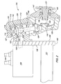
- Fig. 2 shows detail of an embodiment of mechanical drive system 104 mounted on outboard face 154 of plate 102. If both wheels are driven and steered, the same or a substantially similar drive system also may be mounted on the outboard face of plate 103.
- Mechanical drive system 104 may include input shaft 108, intermediate shaft 112, and output shaft 130. The input shaft 108, intermediate shaft 112, and output shaft 130 may be arranged in a generally Z-shaped configuration.
- input shaft 108 may be generally horizontal and parallel to the axis or center line of tubular axle cross member 101.
- Input shaft 108 may be integral with motor 106, and may extend through plate 102.
- Intermediate shaft 112 may be vertical or at an angle ⁇ of between about 90 degrees and about 120 degrees with respect to input shaft 108.
- Output shaft 130 may be generally horizontal and parallel to the axis or center line of tubular axle cross member 101.
- the output shaft may be connected to a flange or hub 131 for wheel mounting (not shown).
- the input shaft, intermediate shaft, and output shaft may have bevel gears attached thereto.
- input shaft 108 may have bevel gear 110 attached to the outer end of the shaft.
- Intermediate shaft 112 may have upper bevel gear 111 attached near the upper end 114 of the shaft, and lower bevel gear 124 at the lower end 117 of the shaft.
- Output shaft 130 may have output bevel gear 128 attached thereto or integral therewith.
- input bevel gear 110 on input shaft 108 may have a smaller diameter than upper and lower bevel gears 111, 124, and the upper and lower bevel gears may have smaller diameters than output bevel gear 128.
- the input shaft, intermediate shaft, and output shaft may be supported for rotation by low friction sleeves or bearings.
- Low friction sleeve or bearing 122 may support input shaft 108 for rotation adjacent the outer end of the shaft.
- Low friction sleeve or bearing 116 may support intermediate shaft 112 adjacent upper end 114, and sleeve or bearing 123 may support intermediate shaft 112 adjacent lower end 117.
- Low friction sleeve or bearing 132 may be mounted on projection 146 to support output bevel gear 128, and low friction sleeve or bearing 133 may support output shaft 130.
- drive system 104 may include a first, stationary or fixed, upper housing 113 and a separate second, pivotable, lower housing 140.
- the upper and lower housings may be pivotally attached to each other.
- the first, upper housing is fixed and the second, lower housing pivots to steer the wheel.
- first or upper housing 113 may be fixed to plate 102 and remains stationary during steering.
- Intermediate shaft 112 may extend between the upper housing and the lower housing.
- the second or lower housing 140 may pivot a maximum of between about 90 degrees and about 180 degrees during steering.
- Lower housing may include removable end cover 147.
- pivoting only the second or lower housing allows motor 106 to remain in a fixed position relative to the axle centerline.
- Hose or cable connections 161 to motor 106 may remain in essentially fixed positions relative to the vehicle chassis.
- hose or cable connections 162 to motor 197 may remain essential fixed during steering. The hoses or cables do not need to swing through the steering arc, and thus may be more compact and durable.
- each second or lower housing 140, 141 may be connected to a drag link 151, 152.
- the drag links may be connected to each other by tie rod 153.
- the drag links also may be connected to a steering linkage (not shown) which may link to steering controls in the vehicle operator station of the fairway mower or other machine.
- lower housing 140 may be supported for pivoting by upper pivot support 115 and lower collar 144.
- Upper pivot support 115 may be a generally inverted L-shaped member.
- the upper pivot support may include lower leg 129, and upper leg 127 having projection 119 extending into low friction sleeve or bearing 125 in upper housing 113.
- Lower collar 144 may be integral with lower housing 140 and may be mounted for rotation around low friction sleeve or bearing 123.
- the invention provides a more economical and simple steerable primary axle for a fairway mower or other machine.
- the steerable primary axle can provide higher torque to the wheels without slipping, and minimizes damage to the turf during steering.
- the steerable primary axle may be used as the front or rear axle, and enables use of smaller, lower cost motors for fairway mowers and other machines. Because the wheels may be steered without moving the motors, the steerable primary axle reduces or minimizes strain on hydraulic hoses or electric cables on the steered wheels. As a result, leakage and premature wear of these hydraulic hoses and cables may be reduced.
Abstract
Description
- This invention relates generally to an apparatus comprising a tubular axle cross member.
- Grass and vegetation cutting machines used for golf course fairways and other applications that require high quality mowing are sometimes referred to as fairway mowers. Fairway mowers use a fixed front axle as the primary drive, and have a steerable rear axle. In other words, the "primary" axle is a driven or powered axle. The front wheels are hydraulically powered to help the machines turn and steer on soft, wet turf, without tearing it. Efforts to power fairway mowers mechanically using differentials and/or over-running clutches have had only limited success.
- Optionally, the rear axle of a fairway mower also may be powered. For example, the rear axle may be powered by a hydraulic motor in an effort to improve traction of the machine. The hydraulic motors, both front and rear, are connected in parallel circuits. If any one wheel of the machine slips, then all hydraulic flow goes to the motor for that wheel, and the machine loses traction.
- Adding a hydraulic motor to each of the steerable wheels of a fairway mower significantly increases the cost and complication of the machine. There is a need for a more economical and simple steerable primary axle on a fairway mower. There is a need for a steerable primary axle that can provide higher torque to the wheels without slipping. There is a need for a steerable primary axle that will minimize damage to the turf during steering. There is a need for a steerable primary axle that may be used as the front or rear axle of the machine. There is a need for smaller, lower cost motors for fairway mowers and similar machines.
- Motors for driving the wheels of fairway mowers and similar machines are connected to hydraulic pumps by hoses that carry high pressure hydraulic fluid. If the driven wheel also is steered, the hydraulic motors, hoses, and hose connections must swing through an arc. The steering movement strains the hoses and hose connections. As a result, the hoses and hose connections may leak or wear prematurely. Similarly, fairway mowers or similar machines with electric wheel motors may strain the electric cables that must swing through an arc when steering. There is a need to reduce or minimize strain on hydraulic hoses or electric cables on steered drive wheels of fairway mowers and similar vehicles. There is a need to reduce leakage and premature wear of these hydraulic hoses and cables.
- It is therefore an object of the present invention to overcome the aforementioned problems.
- An economical and simplified apparatus, which may be a steerable primary axle, is provided preferably for use on a fairway mower or other machine. The steerable primary axle can provide higher torque to the wheels without slipping, and can minimize turf damage when steering. The steerable primary axle may be used as the front or rear axle of the machine, and enables use of smaller, lower cost hydraulic or electric motors. The wheels may be steered without moving the motors, hydraulic hoses or electric cables connecting to the motors. Leakage and premature wear of the hydraulic hoses and cables may be reduced.
- In one embodiment, the apparatus or steerable primary axle may include a tubular axle cross member with a motor attached in a fixed position adjacent each end thereof. Each motor may be mounted to the inboard face of an end plate. A mechanical drive system may include an upper housing mounted to the outboard face of each end plate, and a lower housing connected to a steering linkage to pivot with respect to the upper housing without moving the hydraulic motor or hoses. The upper housing encloses an input shaft extending from the hydraulic motor, an intermediate shaft extends between the upper and lower housings, and an output shaft extends from the lower housing. An input bevel gear may be on the input shaft, an upper bevel gear and a lower bevel gear on the intermediate shaft, and an output bevel gear on the output shaft. For gear reduction between the motor and the output shaft, the input bevel gear may have a smaller diameter than the upper bevel gear, and/or the lower bevel gear may have a smaller diameter than the output bevel gear.
- The steerable primary axle for a fairway mower or other machine may include a pair of motors mounted in fixed positions on opposing ends of an axle. The mechanical drive system may include a pair of input shafts having input bevel gears, a pair of output shafts with output bevel gears and wheel mounts, and a pair of intermediate shafts between the input shafts and output shafts. Each intermediate shaft may have an upper bevel gear meshed with the input bevel gear and a lower bevel gear meshed with the output bevel gear. The output shafts may be enclosed within pivotable housings. A pair of drag links are attached to the pivotable housings and to a steering linkage. The wheels on the wheel mounts may be steered without moving the motors, reducing or minimizing strain on hydraulic hoses or electric cables on the steered wheels.
- In the drawings, an embodiment of the invention is shown:
- Fig. 1
- is a perspective view of a steerable primary axle of a fairway mower according to a first embodiment of the invention.
- Fig. 2
- is a perspective view of an embodiment of a mechanical drive system in the steerable primary axle of Fig. 1.
- In one embodiment of the invention shown in Fig. 1, steerable
primary axle 100 may be provided on a fairway mower, or another machine used for grass or vegetation cutting, agricultural work, or grounds keeping. The steerable primary axle may include tubularaxle cross member 101 that may be mounted to a suspension system adjacent the front or rear of the machine. The embodiment of the steerable primary axle shown in Fig. 1 may be used as either the front or rear axle. Additionally, the invention also may be used on a single steerable drive wheel. - In one embodiment, left and
right plates axle cross member 101. Each plate may have a pair of opposing oblong metal surfaces positioned in generally vertical planes. Each plate may have an inboard face and an outboard face, and a thickness between the faces of between about 0.1 inches and about 1 inch. Each plate may be positioned in a generally vertical plane normal to the axis or center line of tubularaxle cross member 101 and extending upwardly from the end of the tubular axle cross member. - In one embodiment,
motors inboard faces plates Motor 106 may drive the left wheel in forward or reverse, andmotor 107 may drive the right wheel in forward or reverse. Motors 106, 107 may be hydraulic motors that are connected byhydraulic hoses motors - In one embodiment,
motors inboard faces - In one embodiment, each
motor mechanical drive systems outboard face - Fig. 2 shows detail of an embodiment of
mechanical drive system 104 mounted onoutboard face 154 ofplate 102. If both wheels are driven and steered, the same or a substantially similar drive system also may be mounted on the outboard face ofplate 103.Mechanical drive system 104 may includeinput shaft 108,intermediate shaft 112, andoutput shaft 130. Theinput shaft 108,intermediate shaft 112, andoutput shaft 130 may be arranged in a generally Z-shaped configuration. - In one embodiment,
input shaft 108 may be generally horizontal and parallel to the axis or center line of tubularaxle cross member 101.Input shaft 108 may be integral withmotor 106, and may extend throughplate 102.Intermediate shaft 112 may be vertical or at an angle Φ of between about 90 degrees and about 120 degrees with respect toinput shaft 108.Output shaft 130 may be generally horizontal and parallel to the axis or center line of tubularaxle cross member 101. The output shaft may be connected to a flange orhub 131 for wheel mounting (not shown). - In one embodiment, the input shaft, intermediate shaft, and output shaft may have bevel gears attached thereto. For example,
input shaft 108 may havebevel gear 110 attached to the outer end of the shaft.Intermediate shaft 112 may haveupper bevel gear 111 attached near theupper end 114 of the shaft, andlower bevel gear 124 at the lower end 117 of the shaft.Output shaft 130 may haveoutput bevel gear 128 attached thereto or integral therewith. To provide gear reduction and torque multiplication, for example,input bevel gear 110 oninput shaft 108 may have a smaller diameter than upper andlower bevel gears output bevel gear 128. - In one embodiment, the input shaft, intermediate shaft, and output shaft may be supported for rotation by low friction sleeves or bearings. Low friction sleeve or bearing 122 may support
input shaft 108 for rotation adjacent the outer end of the shaft. Low friction sleeve or bearing 116 may supportintermediate shaft 112 adjacentupper end 114, and sleeve or bearing 123 may supportintermediate shaft 112 adjacent lower end 117. Low friction sleeve or bearing 132 may be mounted onprojection 146 to supportoutput bevel gear 128, and low friction sleeve or bearing 133 may supportoutput shaft 130. - In one embodiment,
drive system 104 may include a first, stationary or fixed,upper housing 113 and a separate second, pivotable,lower housing 140. The upper and lower housings may be pivotally attached to each other. The first, upper housing is fixed and the second, lower housing pivots to steer the wheel. For example, first orupper housing 113 may be fixed toplate 102 and remains stationary during steering.Intermediate shaft 112 may extend between the upper housing and the lower housing. The second orlower housing 140 may pivot a maximum of between about 90 degrees and about 180 degrees during steering. Lower housing may includeremovable end cover 147. - In one embodiment, pivoting only the second or lower housing allows
motor 106 to remain in a fixed position relative to the axle centerline. Hose orcable connections 161 tomotor 106 may remain in essentially fixed positions relative to the vehicle chassis. Similarly, hose orcable connections 162 to motor 197 may remain essential fixed during steering. The hoses or cables do not need to swing through the steering arc, and thus may be more compact and durable. - In one embodiment, as shown in Fig. 1, each second or
lower housing drag link tie rod 153. The drag links also may be connected to a steering linkage (not shown) which may link to steering controls in the vehicle operator station of the fairway mower or other machine. - In one embodiment, as shown in Fig. 2,
lower housing 140 may be supported for pivoting byupper pivot support 115 andlower collar 144.Upper pivot support 115 may be a generally inverted L-shaped member. For example, the upper pivot support may includelower leg 129, andupper leg 127 havingprojection 119 extending into low friction sleeve or bearing 125 inupper housing 113.Lower collar 144 may be integral withlower housing 140 and may be mounted for rotation around low friction sleeve orbearing 123. - The invention provides a more economical and simple steerable primary axle for a fairway mower or other machine. The steerable primary axle can provide higher torque to the wheels without slipping, and minimizes damage to the turf during steering. The steerable primary axle may be used as the front or rear axle, and enables use of smaller, lower cost motors for fairway mowers and other machines. Because the wheels may be steered without moving the motors, the steerable primary axle reduces or minimizes strain on hydraulic hoses or electric cables on the steered wheels. As a result, leakage and premature wear of these hydraulic hoses and cables may be reduced.
- Having described a preferred embodiment, it will become apparent that various modifications can be made without departing from the scope of the invention as defined in the accompanying claims.
Claims (10)
- An apparatus comprising a tubular axle cross member (101) with an end plate (102, 103) attached to each end thereof; each end plate (102, 103) having an inboard face (138, 139) and an outboard face (154, 155); a motor (106, 107) mounted to the inboard face (138, 139) of each end plate (102, 103); and a mechanical drive system having an upper housing (113) mounted to the outboard face (154, 155) of each end plate (102, 103) and having a lower housing (140) connected to a steering linkage to pivot the lower housing with (140) respect to the upper housing (113) without pivoting the motor (106, 107).
- The apparatus of claim 1 wherein the motor (106, 107) is hydraulic or electric.
- The apparatus according to claim 1 or 2, characterized in that the upper housing (113) encloses an input shaft (108) extending from each motor (106, 107), the upper and lower housings (113, 140) enclose an intermediate shaft (112) extending between the upper and lower housings (113, 140), and an output shaft (130) extends from the lower housing (140).
- The apparatus according to claim 3, characterized by an input bevel gear (110) on the input shaft (108), an upper bevel gear (111) and a lower bevel gear (124) on the intermediate shaft (112), and an output bevel gear (128) on the output shaft (130).
- The apparatus according to claim 3 or 4, characterized in that the input bevel gear (108) has a smaller diameter than the upper bevel gear (111) and/or that the lower bevel gear (124) has a smaller diameter than the output bevel gear (128).
- An apparatus according to one or several of the claims 3 to 5, characterized in that the input shaft (108) may rotate in forward or reverse; the input bevel gear (108) engaging the upper bevel gear (11); and the output shaft (130) having the output bevel gear (128) on one end of the shaft (103) and a wheel on another end of the output shaft (130); the lower bevel gear (124) engaging the output bevel gear (128); the output shaft (130) pivotable with respect to the motor (106, 107) to steer the wheel.
- The apparatus according to claim 6, characterized in that the lower housing (140) encloses the output bevel gear (128).
- The apparatus according to one or several of the previous claims being a steerable primary axle having wheel mounts attached to the output shafts (130), a pair of drag links (151, 152) attached to the pivotable housings (113, 140) and to a steering linkage.
- The apparatus according to claim 8, characterized in by a tie rod (153) connecting between the pair of drag links (151, 152).
- The apparatus according to one or several of the previous claims, characterized by an inverted L-shaped upper pivot support (115) between the pivotable housing (140) and the stationary housing (113).
Priority Applications (1)
| Application Number | Priority Date | Filing Date | Title |
|---|---|---|---|
| DE602005006075T DE602005006075T3 (en) | 2004-11-23 | 2005-11-04 | Device with a pipe cross member |
Applications Claiming Priority (1)
| Application Number | Priority Date | Filing Date | Title |
|---|---|---|---|
| US10/996,259 US7231999B2 (en) | 2004-11-23 | 2004-11-23 | Steerable primary axle |
Publications (3)
| Publication Number | Publication Date |
|---|---|
| EP1658764A1 true EP1658764A1 (en) | 2006-05-24 |
| EP1658764B1 EP1658764B1 (en) | 2008-04-16 |
| EP1658764B2 EP1658764B2 (en) | 2012-08-01 |
Family
ID=35534719
Family Applications (1)
| Application Number | Title | Priority Date | Filing Date |
|---|---|---|---|
| EP05110374A Active EP1658764B2 (en) | 2004-11-23 | 2005-11-04 | Apparatus comprising a tubular cross member |
Country Status (3)
| Country | Link |
|---|---|
| US (2) | US7231999B2 (en) |
| EP (1) | EP1658764B2 (en) |
| DE (1) | DE602005006075T3 (en) |
Cited By (2)
| Publication number | Priority date | Publication date | Assignee | Title |
|---|---|---|---|---|
| WO2009118084A1 (en) * | 2008-03-27 | 2009-10-01 | Daimler Ag | Wheel hub drive for a motor vehicle |
| PL423575A1 (en) * | 2017-11-24 | 2019-06-03 | Politechnika Koszalinska | Mechanism of a rockerless suspension and steering of the wheeled vehicles wheels |
Families Citing this family (9)
| Publication number | Priority date | Publication date | Assignee | Title |
|---|---|---|---|---|
| DE102005034278A1 (en) * | 2005-07-22 | 2007-04-12 | Daimlerchrysler Ag | Drive unit for a vehicle |
| US8051940B2 (en) * | 2008-03-13 | 2011-11-08 | Dana Heavy Vehicle Systems Group, Llc | Hydraulic assist wheel end |
| US20090297084A1 (en) * | 2008-05-29 | 2009-12-03 | Ziech James F | Preset wheel bearing arrangement |
| NL2002903C2 (en) * | 2009-01-20 | 2010-07-22 | Exodus Holding B V | Drive system for patient support. |
| DE102009033531A1 (en) * | 2009-07-10 | 2011-01-20 | Dr. Ing. H.C. F. Porsche Aktiengesellschaft | Drive device for a motor vehicle with an electric machine having portal axis |
| DE102010010438A1 (en) * | 2010-02-26 | 2011-09-01 | Dr. Ing. H.C. F. Porsche Aktiengesellschaft | Suspension for a motor vehicle with an electrical axis |
| FR2967113B1 (en) * | 2011-12-21 | 2014-05-30 | Poclain Hydraulics Ind | WHEEL SUPPORT PROVIDED WITH HYDRAULIC APPARATUS SUPPLY PIPES |
| US11084371B2 (en) * | 2017-01-10 | 2021-08-10 | Showa Corporation | Motor drive device |
| CN110722969A (en) * | 2019-11-01 | 2020-01-24 | 精进电动科技股份有限公司 | Sunken wheel edge motor drive axle |
Citations (5)
| Publication number | Priority date | Publication date | Assignee | Title |
|---|---|---|---|---|
| EP0110474A1 (en) * | 1982-11-24 | 1984-06-13 | Texas Industries Inc. | Tractor or similar vehicle |
| US4597468A (en) * | 1982-12-06 | 1986-07-01 | Kramer-Werke Gmbh | Compact industrial vehicle |
| US4798260A (en) * | 1986-03-27 | 1989-01-17 | Kubota, Ltd. | Steering apparatus for a front wheel drive tractor |
| US20040055267A1 (en) * | 1994-12-16 | 2004-03-25 | Wright Manufacturing, Inc. | Power mower with riding platform for supporting standing-operator |
| US20040124019A1 (en) * | 2002-12-27 | 2004-07-01 | Clive Harrup | Suspended wheel end powered through trailing arm |
Family Cites Families (16)
| Publication number | Priority date | Publication date | Assignee | Title |
|---|---|---|---|---|
| US674864A (en) * | 1898-09-12 | 1901-05-28 | Willard R Green | Cushioning device for vehicles. |
| US1130285A (en) | 1913-03-07 | 1915-03-02 | Ira Vermilyea | Tractor. |
| US1289851A (en) | 1918-01-19 | 1918-12-31 | Thomas V Marling | Front-wheel drive mechanism. |
| US3469648A (en) * | 1967-05-15 | 1969-09-30 | Allis Chalmers Mfg Co | Hydraulic motor driven steerable wheel |
| DE3034689A1 (en) | 1980-09-15 | 1982-05-06 | Deere & Co., Moline, Ill., US, Niederlassung Deere & Co. European Office, 6800 Mannheim | AGRICULTURAL MACHINE, IN PARTICULAR TRACTOR |
| NL8203382A (en) | 1982-08-31 | 1984-03-16 | Lely Nv C Van Der | TRACTOR. |
| US5203169A (en) | 1990-12-25 | 1993-04-20 | Kanzaki Kokyukoki Mfg. Co., Ltd. | Axle drive apparatus |
| US5148885A (en) * | 1991-03-29 | 1992-09-22 | Weyer Paul P | Steerable utility vehicle |
| US6390227B1 (en) | 1995-03-30 | 2002-05-21 | Kanzaki Kokyukoki Mfg. Co., Ltd. | Axle driving unit for a lawn tractor |
| JP4125435B2 (en) | 1998-12-03 | 2008-07-30 | 株式会社 神崎高級工機製作所 | Traveling vehicle |
| US6457546B1 (en) | 1998-06-05 | 2002-10-01 | Kanzaki Kokyukoki Mfg., Co., Ltd. | Transmission mechanism of vehicle with HST and pressure oil feeding device for the mechanism |
| US6540633B1 (en) | 1998-09-25 | 2003-04-01 | Tuff Torq Corporation | Transmission for speed changing and steering of a vehicle |
| JP2000142153A (en) | 1998-11-11 | 2000-05-23 | Kanzaki Kokyukoki Mfg Co Ltd | Traveling device for vehicle |
| US6312354B1 (en) | 1999-01-22 | 2001-11-06 | Kanzaki Kokyukoki Mfg. Co., Ltd. | Integral hydrostatic transaxle apparatus for driving and steering |
| US6302233B1 (en) * | 2000-06-06 | 2001-10-16 | Spicer Technologies, Inc. | Steering axle for vehicular hydraustatic drive system |
| US6823961B2 (en) * | 2002-05-01 | 2004-11-30 | Cnh America Llc | Skid steer vehicle with axle housing having a double gear reduction |
-
2004
- 2004-11-23 US US10/996,259 patent/US7231999B2/en active Active
-
2005
- 2005-11-04 EP EP05110374A patent/EP1658764B2/en active Active
- 2005-11-04 DE DE602005006075T patent/DE602005006075T3/en active Active
-
2007
- 2007-04-26 US US11/740,317 patent/US7353904B2/en active Active
Patent Citations (5)
| Publication number | Priority date | Publication date | Assignee | Title |
|---|---|---|---|---|
| EP0110474A1 (en) * | 1982-11-24 | 1984-06-13 | Texas Industries Inc. | Tractor or similar vehicle |
| US4597468A (en) * | 1982-12-06 | 1986-07-01 | Kramer-Werke Gmbh | Compact industrial vehicle |
| US4798260A (en) * | 1986-03-27 | 1989-01-17 | Kubota, Ltd. | Steering apparatus for a front wheel drive tractor |
| US20040055267A1 (en) * | 1994-12-16 | 2004-03-25 | Wright Manufacturing, Inc. | Power mower with riding platform for supporting standing-operator |
| US20040124019A1 (en) * | 2002-12-27 | 2004-07-01 | Clive Harrup | Suspended wheel end powered through trailing arm |
Cited By (2)
| Publication number | Priority date | Publication date | Assignee | Title |
|---|---|---|---|---|
| WO2009118084A1 (en) * | 2008-03-27 | 2009-10-01 | Daimler Ag | Wheel hub drive for a motor vehicle |
| PL423575A1 (en) * | 2017-11-24 | 2019-06-03 | Politechnika Koszalinska | Mechanism of a rockerless suspension and steering of the wheeled vehicles wheels |
Also Published As
| Publication number | Publication date |
|---|---|
| DE602005006075T3 (en) | 2012-12-06 |
| US7353904B2 (en) | 2008-04-08 |
| US20070187168A1 (en) | 2007-08-16 |
| US7231999B2 (en) | 2007-06-19 |
| DE602005006075T2 (en) | 2009-05-07 |
| DE602005006075D1 (en) | 2008-05-29 |
| US20060107786A1 (en) | 2006-05-25 |
| EP1658764B2 (en) | 2012-08-01 |
| EP1658764B1 (en) | 2008-04-16 |
Similar Documents
| Publication | Publication Date | Title |
|---|---|---|
| EP1658764B1 (en) | Apparatus comprising a tubular cross member | |
| US6244370B1 (en) | Asymmetrical drive system | |
| US7980339B2 (en) | Power transmission system of hydraulically driven working vehicle | |
| US8109355B2 (en) | Hydrostatic transaxle and hydraulically driven vehicle | |
| US6237708B1 (en) | Working vehicle | |
| US4899525A (en) | Clipping collector equipped with front mower | |
| CA1294559C (en) | Working vehicle | |
| JP3708001B2 (en) | Power take-out structure of work vehicle | |
| CA2465937C (en) | Articulated power transfer apparatus | |
| US3222802A (en) | Self-propelled vehicle and mounting for tool or implement | |
| US4284158A (en) | Detachable differential for vehicle drive train | |
| JP5593449B2 (en) | Tractor | |
| JPH0644844B2 (en) | Grass mower with front mower | |
| JP4567384B2 (en) | Walking type mower and power transmission unit used therefor | |
| JP2626884B2 (en) | Wheel steering device for riding type work machine | |
| KR101195206B1 (en) | Tractor | |
| JP7106446B2 (en) | electric work vehicle | |
| JP2537139B2 (en) | Wheel steering device for riding type agricultural machine | |
| JP4901408B2 (en) | Riding work machine | |
| JP2023157598A (en) | Snow remover | |
| JP2534805Y2 (en) | Mission case support structure for riding lawn mower | |
| JP3412284B2 (en) | Management work vehicle | |
| US3707081A (en) | Gear type coupling | |
| JP6512663B2 (en) | Work vehicle and riding type rice planter as an example thereof | |
| JPS6230501Y2 (en) |
Legal Events
| Date | Code | Title | Description |
|---|---|---|---|
| PUAI | Public reference made under article 153(3) epc to a published international application that has entered the european phase |
Free format text: ORIGINAL CODE: 0009012 |
|
| AK | Designated contracting states |
Kind code of ref document: A1 Designated state(s): AT BE BG CH CY CZ DE DK EE ES FI FR GB GR HU IE IS IT LI LT LU LV MC NL PL PT RO SE SI SK TR |
|
| AX | Request for extension of the european patent |
Extension state: AL BA HR MK YU |
|
| 17P | Request for examination filed |
Effective date: 20061124 |
|
| AKX | Designation fees paid |
Designated state(s): DE GB |
|
| 17Q | First examination report despatched |
Effective date: 20070919 |
|
| GRAP | Despatch of communication of intention to grant a patent |
Free format text: ORIGINAL CODE: EPIDOSNIGR1 |
|
| GRAS | Grant fee paid |
Free format text: ORIGINAL CODE: EPIDOSNIGR3 |
|
| GRAA | (expected) grant |
Free format text: ORIGINAL CODE: 0009210 |
|
| AK | Designated contracting states |
Kind code of ref document: B1 Designated state(s): DE GB |
|
| REF | Corresponds to: |
Ref document number: 602005006075 Country of ref document: DE Date of ref document: 20080529 Kind code of ref document: P |
|
| PLBI | Opposition filed |
Free format text: ORIGINAL CODE: 0009260 |
|
| PLAX | Notice of opposition and request to file observation + time limit sent |
Free format text: ORIGINAL CODE: EPIDOSNOBS2 |
|
| 26 | Opposition filed |
Opponent name: LINDE MATERIAL HANDLING GMBH Effective date: 20090113 |
|
| PLAF | Information modified related to communication of a notice of opposition and request to file observations + time limit |
Free format text: ORIGINAL CODE: EPIDOSCOBS2 |
|
| PLAF | Information modified related to communication of a notice of opposition and request to file observations + time limit |
Free format text: ORIGINAL CODE: EPIDOSCOBS2 |
|
| PLBB | Reply of patent proprietor to notice(s) of opposition received |
Free format text: ORIGINAL CODE: EPIDOSNOBS3 |
|
| PLAY | Examination report in opposition despatched + time limit |
Free format text: ORIGINAL CODE: EPIDOSNORE2 |
|
| PLBC | Reply to examination report in opposition received |
Free format text: ORIGINAL CODE: EPIDOSNORE3 |
|
| PUAH | Patent maintained in amended form |
Free format text: ORIGINAL CODE: 0009272 |
|
| STAA | Information on the status of an ep patent application or granted ep patent |
Free format text: STATUS: PATENT MAINTAINED AS AMENDED |
|
| 27A | Patent maintained in amended form |
Effective date: 20120801 |
|
| AK | Designated contracting states |
Kind code of ref document: B2 Designated state(s): DE GB |
|
| REG | Reference to a national code |
Ref country code: DE Ref legal event code: R102 Ref document number: 602005006075 Country of ref document: DE Effective date: 20120801 |
|
| PGFP | Annual fee paid to national office [announced via postgrant information from national office to epo] |
Ref country code: GB Payment date: 20191127 Year of fee payment: 15 |
|
| GBPC | Gb: european patent ceased through non-payment of renewal fee |
Effective date: 20201104 |
|
| PG25 | Lapsed in a contracting state [announced via postgrant information from national office to epo] |
Ref country code: GB Free format text: LAPSE BECAUSE OF NON-PAYMENT OF DUE FEES Effective date: 20201104 |
|
| PGFP | Annual fee paid to national office [announced via postgrant information from national office to epo] |
Ref country code: DE Payment date: 20231130 Year of fee payment: 19 |