EP1658000B1 - A beverage making device having protrusions at the upper wall of the brewing chamber - Google Patents
A beverage making device having protrusions at the upper wall of the brewing chamber Download PDFInfo
- Publication number
- EP1658000B1 EP1658000B1 EP04769786A EP04769786A EP1658000B1 EP 1658000 B1 EP1658000 B1 EP 1658000B1 EP 04769786 A EP04769786 A EP 04769786A EP 04769786 A EP04769786 A EP 04769786A EP 1658000 B1 EP1658000 B1 EP 1658000B1
- Authority
- EP
- European Patent Office
- Prior art keywords
- upper wall
- brewing chamber
- protrusions
- making device
- pad
- Prior art date
- Legal status (The legal status is an assumption and is not a legal conclusion. Google has not performed a legal analysis and makes no representation as to the accuracy of the status listed.)
- Active
Links
- 235000013361 beverage Nutrition 0.000 title claims abstract description 25
- XLYOFNOQVPJJNP-UHFFFAOYSA-N water Substances O XLYOFNOQVPJJNP-UHFFFAOYSA-N 0.000 claims abstract description 15
- 239000000126 substance Substances 0.000 claims abstract description 9
- 238000013124 brewing process Methods 0.000 claims description 4
- 238000004519 manufacturing process Methods 0.000 claims description 2
- 239000007788 liquid Substances 0.000 description 8
- 238000009826 distribution Methods 0.000 description 5
- 238000000605 extraction Methods 0.000 description 4
- 239000000463 material Substances 0.000 description 3
- 238000010438 heat treatment Methods 0.000 description 2
- 238000000034 method Methods 0.000 description 2
- 238000005086 pumping Methods 0.000 description 2
- 238000007789 sealing Methods 0.000 description 2
- 235000019219 chocolate Nutrition 0.000 description 1
- 238000004140 cleaning Methods 0.000 description 1
- 230000003247 decreasing effect Effects 0.000 description 1
- 229920003002 synthetic resin Polymers 0.000 description 1
- 239000000057 synthetic resin Substances 0.000 description 1
Images


Classifications
-
- A—HUMAN NECESSITIES
- A47—FURNITURE; DOMESTIC ARTICLES OR APPLIANCES; COFFEE MILLS; SPICE MILLS; SUCTION CLEANERS IN GENERAL
- A47J—KITCHEN EQUIPMENT; COFFEE MILLS; SPICE MILLS; APPARATUS FOR MAKING BEVERAGES
- A47J31/00—Apparatus for making beverages
- A47J31/06—Filters or strainers for coffee or tea makers ; Holders therefor
- A47J31/0657—Filters or strainers for coffee or tea makers ; Holders therefor for brewing coffee under pressure, e.g. for espresso machines
- A47J31/0668—Filters or strainers for coffee or tea makers ; Holders therefor for brewing coffee under pressure, e.g. for espresso machines specially adapted for cartridges
- A47J31/0678—Means to separate the cartridge from the bottom of the brewing chamber, e.g. grooves or protrusions
-
- A—HUMAN NECESSITIES
- A47—FURNITURE; DOMESTIC ARTICLES OR APPLIANCES; COFFEE MILLS; SPICE MILLS; SUCTION CLEANERS IN GENERAL
- A47J—KITCHEN EQUIPMENT; COFFEE MILLS; SPICE MILLS; APPARATUS FOR MAKING BEVERAGES
- A47J31/00—Apparatus for making beverages
- A47J31/24—Coffee-making apparatus in which hot water is passed through the filter under pressure, i.e. in which the coffee grounds are extracted under pressure
- A47J31/34—Coffee-making apparatus in which hot water is passed through the filter under pressure, i.e. in which the coffee grounds are extracted under pressure with hot water under liquid pressure
- A47J31/36—Coffee-making apparatus in which hot water is passed through the filter under pressure, i.e. in which the coffee grounds are extracted under pressure with hot water under liquid pressure with mechanical pressure-producing means
- A47J31/3666—Coffee-making apparatus in which hot water is passed through the filter under pressure, i.e. in which the coffee grounds are extracted under pressure with hot water under liquid pressure with mechanical pressure-producing means whereby the loading of the brewing chamber with the brewing material is performed by the user
- A47J31/3676—Cartridges being employed
- A47J31/368—Permeable cartridges being employed
- A47J31/3685—Brewing heads therefor
Definitions
- the invention relates to a beverage making device comprising a brewing chamber for enclosing a pad containing a substance from which the beverage is brewed, the brewing chamber having an upper wall with one or more holes through which heated water can enter the brewing chamber, which upper wall can hinge from a substantially horizontal brewing position, in which the upper wall is a portion of the wall of the brewing chamber into an open position in which the pad can be removed from the brewing chamber, whereby the surface of the upper wall is provided with protrusions having a height of more than 0.5 mm.
- Such a device is described in WO-A-O1/15582 .
- the described device comprises a water reservoir and means for heating the water and pumping it towards the holes in the upper wall of the brewing chamber, so that the heated water will enter the brewing chamber under pressure.
- the brewing chamber is filled with a pad containing a substance, for example ground coffee, and the heated water will pass through the pad, so that the coffee is extracted.
- the liquid (coffee) leaves the brewing chamber through an outflow opening in the bottom of the brewing chamber and arrives in a liquid receiving chamber.
- the liquid receiving chamber comprises an outflow tube extending outside the device, so that the brewed liquid (coffee) can be caught by one or by two cups.
- the portion of the device comprising the upper wall of the brewing chamber can hinge upwards with respect to the stationary part of the brewing chamber to give access to the brewing chamber, so that a new pad can be placed for a next extraction process.
- the part of the device comprising the side wall and the lower wall of the brewing chamber (said stationary part) and the liquid receiving chamber can be removed from the device, for example for cleaning that part or for replacing the part by another, similar part in which the brewing chamber is larger, so that two pads can be placed in it in order to brew enough beverage for two cups instead of one cup.
- a beverage can be made in an extraction process by means of the device, for example to produce coffee, or in a dissolving process, for example to produce a chocolate drink.
- the extracted substance will remain in the pad and the pad with the extracted substance must be removed from the chamber afterwards.
- the substance in the pad will disappear during the brewing process, and the empty pad must be removed.
- the wet pad tends to stick to the upper wall when that upper wall is hinged into its open position. This is especially the case when two pads are placed in the brewing chamber: the upper pad then sticks to the upper wall, while the lower pad remains in the stationary part of the brewing chamber.
- the pad can be removed by hand from the upper wall in its open position, but it is easier to remove the pad or the pads from the stationary part of the brewing chamber.
- the user of the device expects the pad to remain in the stationary part when he or she opens the brewing chamber and therefore may not notice a pad sticking to the upper wall.
- the object of the invention is to provide a beverage making device as described above wherein the pad or, if two pads are present, both pads always remain in the stationary part of the brewing chamber when that chamber is opened.
- a substantial portion of the surface of said upper wall is provided with said protrusions, whereby the distance between every two neighboring protrusions being less than 12 mm, preferably less than 10 mm. Said substantial portion preferably accounts for more than 50% of the surface area of said upper wall, and in a preferred embodiment more than 75%.
- the protrusions may have the form of studs having more or less a cylindrical shape. The protrusions prevent the pad from sticking to the upper wall when the upper wall is hinged upward.
- the device disclosed in WO-A-01/15582 is provided with six protrusions at the surface of the upper wall of the brewing chamber, which protrusions are located at considerable distances from each other. It was found in practice that the pad tends to stick to the hinging upper wall in the disclosed device, despite the presence of the protrusions. However, the tendency to stick can be decreased when certain dimensions of the protrusions are applied.
- the distance between every two neighboring protrusions is less than 6 mm, and preferably the height of the protrusions is more than 0.7 mm, more preferably more that 1 mm.
- the transverse section of the protrusions (i.e. the section parallel to the plane of the upper wall) is substantial circular, with a diameter between 0.5 mm and 3 mm, preferably between 1 mm and 2 mm.
- the distance between every two neighboring protrusions is less than eight times the height of the protrusions, preferably less than five times the height of the protrusions.
- At least a portion of the side wall of a protrusion extends at an angle of more than 60°, preferably more than 75°, relative to the plane of said upper wall, and preferably a portion of each protrusion is substantial cylindrical.
- the protrusions are ribs on the surface of the upper wall. These may be straight ribs, but the ribs may also be concentrically circular ribs. The ribs may also have the shape of circular arcs or the like.
- said upper wall can hinge through more than 60°, preferably more than 70°, more preferably more than 80°.
- a removable part comprising the part of the wall of the brewing chamber other than said upper wall is a portion of a removable part, and said removable part can be taken from the device in order to clean the brewing chamber or to remove the pad.
- the invention also relates to a method of making a beverage by means of a beverage making device, wherein a pad containing a substance from which the beverage is to be brewed is placed in a brewing chamber, the brewing chamber having an upper wall with one or more holes through which heated water enters the brewing chamber, wherein said upper wall is hinged after the brewing process from a substantially horizontal brewing position in which the upper wall is a portion of the wall of the brewing chamber into an open position in which the pad can be removed, wherein a substantial portion of the surface of said upper wall is provided with protrusions having a height of more than 0.5 mm, and wherein the distance between every two neighboring protrusions is less than 12 mm, so that the pad will remain in the brewing chamber when the upper wall is hinged into its open position.
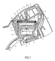
- Fig. 1 shows the relevant portion (i.e. the uppermost portion) of a device for making coffee.
- the other portion of the device which is not shown, comprises a water container and means for heating the water and pumping a predetermined quantity of the heated water through tube 2 to five holes 3 in the upper wall 4 of the brewing chamber 5.
- Brewing chamber 5 has a substantial cylindrical shape, and a disc-like pad (not shown) containing, for example, ground coffee fits in said chamber.
- the lower wall 6 of the brewing chamber 5 is provided with a profile 7 so as to form channels for allowing the brewed coffee to arrive at the central part of the bottom of the brewing chamber 5, so that the liquid can flow to the outflow opening 8 in the lower wall 6.
- the brewed coffee is collected in a liquid receiving chamber 9 and subsequently guided through two outflow tubes 10 extending outside the device to a location where the brewed coffee can be caught by one or by two cups (not shown).
- the brewing chamber 5 as shown in Fig. 1 has a dimension to accommodate a pad containing ground coffee for brewing coffee for one cup. If two cups of coffee are to be brewed, the part 11 of the device can be replaced by another part 11, which other part (not shown) comprises a thinner lower wall 6, so that the height of the brewing chamber 5 is increased and the brewing chamber 5 can accommodate two pads containing ground coffee, or a bigger pad, to brew enough coffee for two cups.
- the device can be opened by hinging the upper part 13 of the device about an axis 14.
- the upper wall 4 of the brewing chamber 5 is connected to said upper part 13, so that the brewing chamber 5 becomes accessible after opening.
- a used pad may then be removed and/or a new pad may be placed in the brewing chamber 5.
- the open position of the brewing chamber allows the replacement of part 11 of the device by another one having a larger brewing chamber 5.
- the tube 2 is made of a flexible material.
- the part of the device comprising the brewing chamber 5 (except for its upper wall 4), the liquid receiving chamber 9, and the outflow tubes 10 is removable from the device, so that the part can be cleaned.
- the upper wall 4 of the brewing chamber 5 has a disc-like shape and is clamped in a connecting piece 16 comprising a central water duct 17 which is connected to tube 2, as is shown in Figs. 1 and 2 .
- a distribution plate 18 having a disc-like shape and comprising recesses in the material to guide the heated water coming from the tube 2 and the water duct 17 to the five holes 3 in the upper wall 4.
- a sealing ring 19 to provide a watertight sealing between the removable part 11 and the upper wall 4 when the brewing chamber 5 is closed ( Fig. 1 ).
- the main portion of the surface of the upper wall 4 is provided with protrusions 21.
- the height of the protrusions 21 is about 1 mm, and the distance between the protrusions 21 is about 4 mm.
- Fig. 3 is the same sectional view of the upper wall 4 of the brewing chamber 5 as is shown in Figs. 1 and 2 , but on a larger scale.
- the upper wall 4 is made of a synthetic resin material.
- the upper wall 4 is provided with an annular protrusion 22 which can surround the distribution plate 18 and which clamps in the connecting piece 16.
- Fig. 4 is a view of the lower side of the upper wall 4 and shows the distribution of the protrusions 21 over the lower side of the upper wall 4.
- Fig. 4 , and also Fig. 5 furthermore show the locations of the five holes 3 in the upper wall 4.
- Fig. 5 is a view of the upper side of the upper wall 4.
- the annular protrusion 22 is provided with a flat (straight) portion 23 corresponding to a flat portion at the edge of distribution plate 18, so that said distribution plate fits between the upper wall 4 and the connecting piece 16 in one position only.
- the protrusions 21 at the lower side of the upper wall 4 of the brewing chamber 5 achieve that the wet pad will not stick to the upper wall 4 when the brewing chamber 5 is opened.
Abstract
Description
- The invention relates to a beverage making device comprising a brewing chamber for enclosing a pad containing a substance from which the beverage is brewed, the brewing chamber having an upper wall with one or more holes through which heated water can enter the brewing chamber, which upper wall can hinge from a substantially horizontal brewing position, in which the upper wall is a portion of the wall of the brewing chamber into an open position in which the pad can be removed from the brewing chamber, whereby the surface of the upper wall is provided with protrusions having a height of more than 0.5 mm.
- Such a device is described in
WO-A-O1/15582 - A beverage can be made in an extraction process by means of the device, for example to produce coffee, or in a dissolving process, for example to produce a chocolate drink. In the case of an extraction process, the extracted substance will remain in the pad and the pad with the extracted substance must be removed from the chamber afterwards. In the case of a dissolving process, the substance in the pad will disappear during the brewing process, and the empty pad must be removed.
- It was found in practice that the wet pad tends to stick to the upper wall when that upper wall is hinged into its open position. This is especially the case when two pads are placed in the brewing chamber: the upper pad then sticks to the upper wall, while the lower pad remains in the stationary part of the brewing chamber. Of course the pad can be removed by hand from the upper wall in its open position, but it is easier to remove the pad or the pads from the stationary part of the brewing chamber. Furthermore, the user of the device expects the pad to remain in the stationary part when he or she opens the brewing chamber and therefore may not notice a pad sticking to the upper wall.
- The object of the invention is to provide a beverage making device as described above wherein the pad or, if two pads are present, both pads always remain in the stationary part of the brewing chamber when that chamber is opened.
- To accomplish that objective, a substantial portion of the surface of said upper wall is provided with said protrusions, whereby the distance between every two neighboring protrusions being less than 12 mm, preferably less than 10 mm. Said substantial portion preferably accounts for more than 50% of the surface area of said upper wall, and in a preferred embodiment more than 75%. The protrusions may have the form of studs having more or less a cylindrical shape. The protrusions prevent the pad from sticking to the upper wall when the upper wall is hinged upward.
- The device disclosed in
WO-A-01/15582 - In one preferred embodiment, the distance between every two neighboring protrusions is less than 6 mm, and preferably the height of the protrusions is more than 0.7 mm, more preferably more that 1 mm.
- In one preferred embodiment, the transverse section of the protrusions (i.e. the section parallel to the plane of the upper wall) is substantial circular, with a diameter between 0.5 mm and 3 mm, preferably between 1 mm and 2 mm.
- Preferably, the distance between every two neighboring protrusions is less than eight times the height of the protrusions, preferably less than five times the height of the protrusions. The higher the protrusions, the greater the distance between the protrusions can be.
- In one preferred embodiment, at least a portion of the side wall of a protrusion extends at an angle of more than 60°, preferably more than 75°, relative to the plane of said upper wall, and preferably a portion of each protrusion is substantial cylindrical.
- In another preferred embodiment, the protrusions are ribs on the surface of the upper wall. These may be straight ribs, but the ribs may also be concentrically circular ribs. The ribs may also have the shape of circular arcs or the like.
- To achieve a good access to the brewing chamber when that chamber is opened, said upper wall can hinge through more than 60°, preferably more than 70°, more preferably more than 80°.
- In one preferred embodiment, a removable part comprising the part of the wall of the brewing chamber other than said upper wall is a portion of a removable part, and said removable part can be taken from the device in order to clean the brewing chamber or to remove the pad.
- The invention also relates to a method of making a beverage by means of a beverage making device, wherein a pad containing a substance from which the beverage is to be brewed is placed in a brewing chamber, the brewing chamber having an upper wall with one or more holes through which heated water enters the brewing chamber, wherein said upper wall is hinged after the brewing process from a substantially horizontal brewing position in which the upper wall is a portion of the wall of the brewing chamber into an open position in which the pad can be removed, wherein a substantial portion of the surface of said upper wall is provided with protrusions having a height of more than 0.5 mm, and wherein the distance between every two neighboring protrusions is less than 12 mm, so that the pad will remain in the brewing chamber when the upper wall is hinged into its open position.
- The invention will now be explained by means of a description of an embodiment of a device for making coffee, in which reference is made to the drawing, in which:
-
Fig. 1 is a sectional view of a portion of the device, -
Fig. 2 shows the device with the brewing chamber in open position, -
Fig. 3 is a sectional view of the upper wall of the brewing chamber, -
Fig. 4 is a bottom view of the upper wall according toFig. 3 , and -
Fig. 5 is a top view of the upper wall according toFig. 3 . -
Fig. 1 shows the relevant portion (i.e. the uppermost portion) of a device for making coffee. The other portion of the device, which is not shown, comprises a water container and means for heating the water and pumping a predetermined quantity of the heated water throughtube 2 to fiveholes 3 in theupper wall 4 of thebrewing chamber 5. In the sectional view ofFig. 1 , only onehole 3 in theupper wall 4 is shown.Brewing chamber 5 has a substantial cylindrical shape, and a disc-like pad (not shown) containing, for example, ground coffee fits in said chamber. - The
lower wall 6 of thebrewing chamber 5 is provided with aprofile 7 so as to form channels for allowing the brewed coffee to arrive at the central part of the bottom of thebrewing chamber 5, so that the liquid can flow to the outflow opening 8 in thelower wall 6. The brewed coffee is collected in aliquid receiving chamber 9 and subsequently guided through twooutflow tubes 10 extending outside the device to a location where the brewed coffee can be caught by one or by two cups (not shown). There are twooutflow tubes 10 parallel to each other, so that eachoutflow tube 10 can guide brewed coffee to one of two cups, which cups stand near each other. If only one cup is to be filled, bothoutflow tubes 10 will guide the brewed coffee to the same cup. Since the twooutflow tubes 10 are located on either side of the plane of drawing, they are not visible in the sectional views ofFig. 1 andFig. 2 . - The
brewing chamber 5 as shown inFig. 1 has a dimension to accommodate a pad containing ground coffee for brewing coffee for one cup. If two cups of coffee are to be brewed, thepart 11 of the device can be replaced by anotherpart 11, which other part (not shown) comprises a thinnerlower wall 6, so that the height of thebrewing chamber 5 is increased and thebrewing chamber 5 can accommodate two pads containing ground coffee, or a bigger pad, to brew enough coffee for two cups. - As is shown in
Fig. 2 byarrow 12, the device can be opened by hinging theupper part 13 of the device about anaxis 14. Theupper wall 4 of thebrewing chamber 5 is connected to saidupper part 13, so that thebrewing chamber 5 becomes accessible after opening. A used pad may then be removed and/or a new pad may be placed in thebrewing chamber 5. If the next brewing process is to be performed with two pads, the open position of the brewing chamber allows the replacement ofpart 11 of the device by another one having alarger brewing chamber 5. To enable the hinging movement of theupper part 13, thetube 2 is made of a flexible material. - In the opened position of the device as shown in
Fig. 2 , the part of the device comprising the brewing chamber 5 (except for its upper wall 4), theliquid receiving chamber 9, and theoutflow tubes 10 is removable from the device, so that the part can be cleaned. - The
upper wall 4 of thebrewing chamber 5 has a disc-like shape and is clamped in a connectingpiece 16 comprising acentral water duct 17 which is connected totube 2, as is shown inFigs. 1 and2 . Between theupper wall 4 and the connectingpiece 16 there is adistribution plate 18, having a disc-like shape and comprising recesses in the material to guide the heated water coming from thetube 2 and thewater duct 17 to the fiveholes 3 in theupper wall 4. Around the connectingpiece 16 there is asealing ring 19 to provide a watertight sealing between theremovable part 11 and theupper wall 4 when thebrewing chamber 5 is closed (Fig. 1 ). - At the lower side of the
upper wall 4, the main portion of the surface of theupper wall 4 is provided withprotrusions 21. In this example, the height of theprotrusions 21 is about 1 mm, and the distance between theprotrusions 21 is about 4 mm. -
Fig. 3 is the same sectional view of theupper wall 4 of thebrewing chamber 5 as is shown inFigs. 1 and2 , but on a larger scale. Theupper wall 4 is made of a synthetic resin material. At its upper side, theupper wall 4 is provided with anannular protrusion 22 which can surround thedistribution plate 18 and which clamps in the connectingpiece 16. -
Fig. 4 is a view of the lower side of theupper wall 4 and shows the distribution of theprotrusions 21 over the lower side of theupper wall 4.Fig. 4 , and alsoFig. 5 , furthermore show the locations of the fiveholes 3 in theupper wall 4. -
Fig. 5 is a view of the upper side of theupper wall 4. Theannular protrusion 22 is provided with a flat (straight)portion 23 corresponding to a flat portion at the edge ofdistribution plate 18, so that said distribution plate fits between theupper wall 4 and the connectingpiece 16 in one position only. - The
protrusions 21 at the lower side of theupper wall 4 of thebrewing chamber 5 achieve that the wet pad will not stick to theupper wall 4 when thebrewing chamber 5 is opened. - The embodiment as described above is only an example; a great many other embodiments are possible, including embodiments in which the
protrusions 21 at the lower side of theupper wall 4 of the device have a different shape.
Claims (11)
- A beverage making device comprising a brewing chamber (5) for enclosing a pad containing a substance from which the beverage is brewed, the brewing chamber (5) having an upper wall (4) with one or more holes (3) through which heated water can enter the brewing chamber (5), which upper wall (4) can hinge from a substantially horizontal brewing position in which the upper wall (4) is a portion of the wall of the brewing chamber (5) into an open position in which the pad can be removed from the brewing chamber (5), whereby the surface of the upper wall (4) is provided with protrusions (21) having a height of more than 0.5 mm, characterized in that a substantial portion of the surface of said upper wall (4) is provided with said protrusions (21), whereby the distance between every two neighboring protrusions (21) being less than 12 mm.
- A beverage making device as claimed in claim 1, characterized in that the distance between every two neighboring protrusions (21) is less than 6 mm.
- A beverage making device as claimed in any one of the preceding claims, characterized in that the height of the protrusions (21) is more than 0.7 mm, preferably more than 1 mm.
- A beverage making device as claimed in any one of the preceding claims, characterized in that the transverse section of the protrusions (21) is substantial circular, with a diameter between 0.5 mm and 3 mm, preferably between 1 mm and 2 mm.
- A beverage making device as claimed in any one of the preceding claims, characterized in that the distance between every two neighboring protrusions (21) is less than eight times the height of the protrusions (21), preferably less than five times the height of the protrusions (21).
- A beverage making device as claimed in any one of the preceding claims, characterized in that at least a portion of the side wall of a protrusion (21) extends at an angle of more than 60°, preferably more than 75°, relative to the plane of said upper wall (4).
- A beverage making device as claimed in any one of the preceding claims, characterized in that a portion of each protrusion (21) is substantially cylindrical.
- A beverage making device as claimed in any one of claims 1 to 6, characterized in that the protrusions (21) are ribs on the surface of the upper wall (4).
- A beverage making device as claimed in any one of the preceding claims, characterized in that said upper wall (4) can hinge through more than 60°, preferably more than 70°, more preferably more than 80°.
- A beverage making device as claimed in any one of the preceding claims, characterized by a removable part comprising the part of the wall of the brewing chamber (5) other than said upper wall (4), which removable part can be taken from the device in order to clean the brewing chamber (5) or to remove the pad.
- A method of making a beverage by means of a beverage making device, wherein a pad containing a substance from which the beverage is to be brewed is placed in a brewing chamber (5), said brewing chamber (5) having an upper wall (4) with one or more holes (3) through which heated water can enter the brewing chamber (5), wherein said upper wall (4) is hinged after the brewing process from a substantially horizontal brewing position in which the upper wall (4) is a portion of the wall of the brewing chamber (5) into an open position in which the pad is removed, whereby the surface of the upper wall (4) is provided with protrusions (21) having a height of more than 0.5 mm, characterized in that a substantial portion of the surface of said upper wall (4) is provided with such protrusions (21), the distance between every two neighboring protrusions (21) being less than 12 mm, so that the pad will remain in the brewing chamber (5) when the upper wall (4) is hinged into its open position.
Priority Applications (1)
| Application Number | Priority Date | Filing Date | Title |
|---|---|---|---|
| EP04769786A EP1658000B1 (en) | 2003-08-18 | 2004-07-30 | A beverage making device having protrusions at the upper wall of the brewing chamber |
Applications Claiming Priority (3)
| Application Number | Priority Date | Filing Date | Title |
|---|---|---|---|
| EP03102580 | 2003-08-18 | ||
| PCT/IB2004/051337 WO2005016092A1 (en) | 2003-08-18 | 2004-07-30 | A beverage making device having protrusions at the upper wall of the brewing chamber |
| EP04769786A EP1658000B1 (en) | 2003-08-18 | 2004-07-30 | A beverage making device having protrusions at the upper wall of the brewing chamber |
Publications (2)
| Publication Number | Publication Date |
|---|---|
| EP1658000A1 EP1658000A1 (en) | 2006-05-24 |
| EP1658000B1 true EP1658000B1 (en) | 2010-07-28 |
Family
ID=33442866
Family Applications (1)
| Application Number | Title | Priority Date | Filing Date |
|---|---|---|---|
| EP04769786A Active EP1658000B1 (en) | 2003-08-18 | 2004-07-30 | A beverage making device having protrusions at the upper wall of the brewing chamber |
Country Status (8)
| Country | Link |
|---|---|
| US (1) | US20060225576A1 (en) |
| EP (1) | EP1658000B1 (en) |
| JP (1) | JP4668192B2 (en) |
| CN (2) | CN100563526C (en) |
| AT (1) | ATE475340T1 (en) |
| DE (2) | DE602004028375D1 (en) |
| ES (1) | ES2349287T3 (en) |
| WO (1) | WO2005016092A1 (en) |
Families Citing this family (17)
| Publication number | Priority date | Publication date | Assignee | Title |
|---|---|---|---|---|
| DE102005049244A1 (en) * | 2005-10-14 | 2007-04-19 | BSH Bosch und Siemens Hausgeräte GmbH | Padholder |
| JP2009517164A (en) | 2005-12-01 | 2009-04-30 | コーニンクレッカ フィリップス エレクトロニクス エヌ ヴィ | Tea conditioning apparatus with improved collection chamber |
| PL2071988T3 (en) * | 2007-12-18 | 2011-07-29 | Nestec Sa | Device for preparing a beverage with removable injection member |
| JP2010082047A (en) * | 2008-09-30 | 2010-04-15 | Toshiba Electric Appliance Co Ltd | Beverage dispenser |
| EP2680726B1 (en) | 2011-03-04 | 2017-09-13 | Bunn-O-Matic Corporation | Brewer with compacting force activation |
| US10368682B2 (en) | 2012-01-24 | 2019-08-06 | Bunn-O-Matic Corporation | Brewer |
| ES2647149T3 (en) * | 2013-12-31 | 2017-12-19 | Koninklijke Philips N.V. | Beverage machine |
| CN106308522B (en) * | 2015-06-24 | 2019-12-03 | 广东美的生活电器制造有限公司 | The brewing locking device of coffee machine and coffee machine with it |
| NL2017284B1 (en) | 2016-08-03 | 2018-02-14 | Douwe Egberts Bv | System and method for preparing a beverage field and background |
| NL2017281B1 (en) | 2016-08-03 | 2018-02-14 | Douwe Egberts Bv | System for preparing a beverage |
| NL2017277B1 (en) | 2016-08-03 | 2018-02-14 | Douwe Egberts Bv | Apparatus and method for preparing a beverage and system comprising the apparatus and an exchangeable capsule |
| NL2017285B1 (en) | 2016-08-03 | 2018-02-14 | Douwe Egberts Bv | System, apparatus, method, capsule and kit of capsules for preparing a beverage |
| NL2019218B1 (en) | 2016-08-03 | 2018-07-06 | Douwe Egberts Bv | Capsule, system and use of the system for preparing double beverages like a double espresso, a double lungo and a double ristretto |
| NL2017278B1 (en) * | 2016-08-03 | 2018-02-14 | Douwe Egberts Bv | System, apparatus, method, capsule and kit of capsules for preparing a beverage |
| NL2017279B1 (en) | 2016-08-03 | 2018-02-14 | Douwe Egberts Bv | System for preparing a beverage |
| NL2017283B1 (en) | 2016-08-03 | 2018-02-14 | Douwe Egberts Bv | System and apparatus for preparing a beverage |
| DE102017212433A1 (en) * | 2017-07-20 | 2019-01-24 | Gebr. Echtermann GmbH & Co. KG | Lid swivel joint and cooking boiler system with hinged lid |
Family Cites Families (12)
| Publication number | Priority date | Publication date | Assignee | Title |
|---|---|---|---|---|
| US3561349A (en) * | 1968-05-20 | 1971-02-09 | Farmer Bros Co | Brewing means for prepackaged coffee |
| US4735810A (en) * | 1986-11-07 | 1988-04-05 | Dacal Manuel G | Coffee infusion bag |
| DE69022847T2 (en) * | 1990-07-27 | 1996-03-14 | Nestle Sa | Brewing device for closed portion packs. |
| DK0521187T3 (en) * | 1991-07-05 | 1996-03-18 | Nestle Sa | Device for extraction of cartridges that can be adapted to all espresso machines |
| ATE260066T1 (en) * | 1992-07-20 | 2004-03-15 | Nestle Sa | DEVICE FOR EXTRACTING OPERASURE, DEFORMABLE PORTION PACKS |
| CH685667A5 (en) * | 1993-10-18 | 1995-09-15 | Max Hugentobler | Filter unit for making filter coffee. |
| US6079315A (en) * | 1999-01-19 | 2000-06-27 | Keurig, Inc. | Beverage filter cartridge holder |
| NL1012847C2 (en) * | 1999-08-17 | 2001-02-20 | Sara Lee De Nv | Coffee preparation device. |
| US6499388B2 (en) * | 2000-06-14 | 2002-12-31 | Fianara Interational B. V. | Coffee machine for brewing coffee power pre-packed in a cartridge |
| DE60111920T2 (en) * | 2001-04-05 | 2006-01-12 | Mövenpick - Holding | Kaffeeextrahierungssystem |
| DK1277428T3 (en) * | 2001-07-20 | 2006-01-09 | Nestle Sa | Coffee machine intended for a vehicle |
| NL1020735C1 (en) * | 2002-05-31 | 2002-07-15 | Antonius Klaassen | Device is for preparing extract with foam layer and is at least with container with inner space for extract, upright side wall and outflow aperture for emission of formed extract, water under pressure being fed to upper side of container |
-
2004
- 2004-07-30 ES ES04769786T patent/ES2349287T3/en active Active
- 2004-07-30 CN CNB2004800236911A patent/CN100563526C/en not_active Expired - Fee Related
- 2004-07-30 JP JP2006523712A patent/JP4668192B2/en not_active Expired - Fee Related
- 2004-07-30 DE DE602004028375T patent/DE602004028375D1/en active Active
- 2004-07-30 US US10/568,374 patent/US20060225576A1/en not_active Abandoned
- 2004-07-30 WO PCT/IB2004/051337 patent/WO2005016092A1/en active Application Filing
- 2004-07-30 EP EP04769786A patent/EP1658000B1/en active Active
- 2004-07-30 AT AT04769786T patent/ATE475340T1/en not_active IP Right Cessation
- 2004-08-06 DE DE202004012327U patent/DE202004012327U1/en not_active Expired - Lifetime
- 2004-08-13 CN CNU2004200740614U patent/CN2848059Y/en not_active Expired - Lifetime
Also Published As
| Publication number | Publication date |
|---|---|
| DE602004028375D1 (en) | 2010-09-09 |
| JP2007502640A (en) | 2007-02-15 |
| US20060225576A1 (en) | 2006-10-12 |
| CN100563526C (en) | 2009-12-02 |
| CN2848059Y (en) | 2006-12-20 |
| EP1658000A1 (en) | 2006-05-24 |
| JP4668192B2 (en) | 2011-04-13 |
| ES2349287T3 (en) | 2010-12-29 |
| DE202004012327U1 (en) | 2004-11-04 |
| WO2005016092A1 (en) | 2005-02-24 |
| CN1886077A (en) | 2006-12-27 |
| ATE475340T1 (en) | 2010-08-15 |
Similar Documents
| Publication | Publication Date | Title |
|---|---|---|
| EP1658000B1 (en) | A beverage making device having protrusions at the upper wall of the brewing chamber | |
| US20060225577A1 (en) | Beverage making device comprising a brewing chamber and a water outlet | |
| AU2017204278B2 (en) | Filter vessel | |
| US7032503B2 (en) | Brew station for coffee drinks | |
| JP5355567B2 (en) | Support part having two surfaces for supporting a cup or other container in a beverage production apparatus | |
| US20060180030A1 (en) | Hot beverage maker brew basket adaptor | |
| US20120216682A1 (en) | Tea-maker having a closable pouring spout | |
| EP2091392A2 (en) | Insert for filter holders of coffee machines, particularly for espresso coffee machines | |
| US5485778A (en) | Beverage brewing apparatus | |
| US20120118167A1 (en) | Tea making device having an improved liquid collection chamber | |
| EP1691650B1 (en) | Beverage making device comprising a brewing chamber for enclosing a pad | |
| DK3225142T3 (en) | coffeemaker | |
| JP2017507849A (en) | Replaceable capsules for preparing leaching of powdered products and associated methods for obtaining this leaching | |
| US20070131119A1 (en) | Coffee maker having a filter support incorporating a sieve | |
| US20210330114A1 (en) | Portable coffee drip-brewer | |
| US20200015619A1 (en) | French Press | |
| EP2767198B1 (en) | A filter holder for an espresso coffee machine | |
| KR102062780B1 (en) | Portable apparatus for extracting beverage | |
| JP3148701B2 (en) | Brewed coffee maker | |
| AU612447B2 (en) | Electrically operated hot beverage maker | |
| TW202245660A (en) | Beverage extractor | |
| RU2575001C2 (en) | Distribution head for machine for preparing beverage | |
| GB2512816A (en) | A filter holder for an espresso coffee machine |
Legal Events
| Date | Code | Title | Description |
|---|---|---|---|
| PUAI | Public reference made under article 153(3) epc to a published international application that has entered the european phase |
Free format text: ORIGINAL CODE: 0009012 |
|
| 17P | Request for examination filed |
Effective date: 20060320 |
|
| AK | Designated contracting states |
Kind code of ref document: A1 Designated state(s): AT BE BG CH CY CZ DE DK EE ES FI FR GB GR HU IE IT LI LU MC NL PL PT RO SE SI SK TR |
|
| 17Q | First examination report despatched |
Effective date: 20060711 |
|
| DAX | Request for extension of the european patent (deleted) | ||
| GRAP | Despatch of communication of intention to grant a patent |
Free format text: ORIGINAL CODE: EPIDOSNIGR1 |
|
| GRAS | Grant fee paid |
Free format text: ORIGINAL CODE: EPIDOSNIGR3 |
|
| GRAA | (expected) grant |
Free format text: ORIGINAL CODE: 0009210 |
|
| AK | Designated contracting states |
Kind code of ref document: B1 Designated state(s): AT BE BG CH CY CZ DE DK EE ES FI FR GB GR HU IE IT LI LU MC NL PL PT RO SE SI SK TR |
|
| REG | Reference to a national code |
Ref country code: GB Ref legal event code: FG4D |
|
| REG | Reference to a national code |
Ref country code: CH Ref legal event code: EP |
|
| REG | Reference to a national code |
Ref country code: IE Ref legal event code: FG4D |
|
| REF | Corresponds to: |
Ref document number: 602004028375 Country of ref document: DE Date of ref document: 20100909 Kind code of ref document: P |
|
| REG | Reference to a national code |
Ref country code: NL Ref legal event code: VDEP Effective date: 20100728 |
|
| REG | Reference to a national code |
Ref country code: ES Ref legal event code: FG2A Effective date: 20101216 |
|
| PG25 | Lapsed in a contracting state [announced via postgrant information from national office to epo] |
Ref country code: NL Free format text: LAPSE BECAUSE OF FAILURE TO SUBMIT A TRANSLATION OF THE DESCRIPTION OR TO PAY THE FEE WITHIN THE PRESCRIBED TIME-LIMIT Effective date: 20100728 Ref country code: FI Free format text: LAPSE BECAUSE OF FAILURE TO SUBMIT A TRANSLATION OF THE DESCRIPTION OR TO PAY THE FEE WITHIN THE PRESCRIBED TIME-LIMIT Effective date: 20100728 Ref country code: AT Free format text: LAPSE BECAUSE OF FAILURE TO SUBMIT A TRANSLATION OF THE DESCRIPTION OR TO PAY THE FEE WITHIN THE PRESCRIBED TIME-LIMIT Effective date: 20100728 |
|
| PG25 | Lapsed in a contracting state [announced via postgrant information from national office to epo] |
Ref country code: MC Free format text: LAPSE BECAUSE OF NON-PAYMENT OF DUE FEES Effective date: 20100731 Ref country code: PL Free format text: LAPSE BECAUSE OF FAILURE TO SUBMIT A TRANSLATION OF THE DESCRIPTION OR TO PAY THE FEE WITHIN THE PRESCRIBED TIME-LIMIT Effective date: 20100728 Ref country code: PT Free format text: LAPSE BECAUSE OF FAILURE TO SUBMIT A TRANSLATION OF THE DESCRIPTION OR TO PAY THE FEE WITHIN THE PRESCRIBED TIME-LIMIT Effective date: 20101129 Ref country code: SI Free format text: LAPSE BECAUSE OF FAILURE TO SUBMIT A TRANSLATION OF THE DESCRIPTION OR TO PAY THE FEE WITHIN THE PRESCRIBED TIME-LIMIT Effective date: 20100728 Ref country code: BG Free format text: LAPSE BECAUSE OF FAILURE TO SUBMIT A TRANSLATION OF THE DESCRIPTION OR TO PAY THE FEE WITHIN THE PRESCRIBED TIME-LIMIT Effective date: 20101028 Ref country code: CY Free format text: LAPSE BECAUSE OF FAILURE TO SUBMIT A TRANSLATION OF THE DESCRIPTION OR TO PAY THE FEE WITHIN THE PRESCRIBED TIME-LIMIT Effective date: 20100728 |
|
| REG | Reference to a national code |
Ref country code: CH Ref legal event code: PL |
|
| PG25 | Lapsed in a contracting state [announced via postgrant information from national office to epo] |
Ref country code: GR Free format text: LAPSE BECAUSE OF FAILURE TO SUBMIT A TRANSLATION OF THE DESCRIPTION OR TO PAY THE FEE WITHIN THE PRESCRIBED TIME-LIMIT Effective date: 20101029 Ref country code: SE Free format text: LAPSE BECAUSE OF FAILURE TO SUBMIT A TRANSLATION OF THE DESCRIPTION OR TO PAY THE FEE WITHIN THE PRESCRIBED TIME-LIMIT Effective date: 20100728 Ref country code: BE Free format text: LAPSE BECAUSE OF FAILURE TO SUBMIT A TRANSLATION OF THE DESCRIPTION OR TO PAY THE FEE WITHIN THE PRESCRIBED TIME-LIMIT Effective date: 20100728 |
|
| PG25 | Lapsed in a contracting state [announced via postgrant information from national office to epo] |
Ref country code: CH Free format text: LAPSE BECAUSE OF NON-PAYMENT OF DUE FEES Effective date: 20100731 Ref country code: DK Free format text: LAPSE BECAUSE OF FAILURE TO SUBMIT A TRANSLATION OF THE DESCRIPTION OR TO PAY THE FEE WITHIN THE PRESCRIBED TIME-LIMIT Effective date: 20100728 Ref country code: LI Free format text: LAPSE BECAUSE OF NON-PAYMENT OF DUE FEES Effective date: 20100731 |
|
| PG25 | Lapsed in a contracting state [announced via postgrant information from national office to epo] |
Ref country code: RO Free format text: LAPSE BECAUSE OF FAILURE TO SUBMIT A TRANSLATION OF THE DESCRIPTION OR TO PAY THE FEE WITHIN THE PRESCRIBED TIME-LIMIT Effective date: 20100728 Ref country code: CZ Free format text: LAPSE BECAUSE OF FAILURE TO SUBMIT A TRANSLATION OF THE DESCRIPTION OR TO PAY THE FEE WITHIN THE PRESCRIBED TIME-LIMIT Effective date: 20100728 Ref country code: EE Free format text: LAPSE BECAUSE OF FAILURE TO SUBMIT A TRANSLATION OF THE DESCRIPTION OR TO PAY THE FEE WITHIN THE PRESCRIBED TIME-LIMIT Effective date: 20100728 Ref country code: SK Free format text: LAPSE BECAUSE OF FAILURE TO SUBMIT A TRANSLATION OF THE DESCRIPTION OR TO PAY THE FEE WITHIN THE PRESCRIBED TIME-LIMIT Effective date: 20100728 |
|
| PLBE | No opposition filed within time limit |
Free format text: ORIGINAL CODE: 0009261 |
|
| STAA | Information on the status of an ep patent application or granted ep patent |
Free format text: STATUS: NO OPPOSITION FILED WITHIN TIME LIMIT |
|
| 26N | No opposition filed |
Effective date: 20110429 |
|
| PG25 | Lapsed in a contracting state [announced via postgrant information from national office to epo] |
Ref country code: IE Free format text: LAPSE BECAUSE OF NON-PAYMENT OF DUE FEES Effective date: 20100730 |
|
| REG | Reference to a national code |
Ref country code: DE Ref legal event code: R097 Ref document number: 602004028375 Country of ref document: DE Effective date: 20110429 |
|
| PG25 | Lapsed in a contracting state [announced via postgrant information from national office to epo] |
Ref country code: LU Free format text: LAPSE BECAUSE OF NON-PAYMENT OF DUE FEES Effective date: 20100730 Ref country code: HU Free format text: LAPSE BECAUSE OF FAILURE TO SUBMIT A TRANSLATION OF THE DESCRIPTION OR TO PAY THE FEE WITHIN THE PRESCRIBED TIME-LIMIT Effective date: 20110129 |
|
| PG25 | Lapsed in a contracting state [announced via postgrant information from national office to epo] |
Ref country code: TR Free format text: LAPSE BECAUSE OF FAILURE TO SUBMIT A TRANSLATION OF THE DESCRIPTION OR TO PAY THE FEE WITHIN THE PRESCRIBED TIME-LIMIT Effective date: 20100728 |
|
| REG | Reference to a national code |
Ref country code: ES Ref legal event code: PC2A Owner name: KONINKLIJKE PHILIPS N.V. Effective date: 20140221 |
|
| REG | Reference to a national code |
Ref country code: DE Ref legal event code: R082 Ref document number: 602004028375 Country of ref document: DE Representative=s name: MEISSNER, BOLTE & PARTNER GBR, DE |
|
| REG | Reference to a national code |
Ref country code: DE Ref legal event code: R082 Ref document number: 602004028375 Country of ref document: DE Representative=s name: MEISSNER BOLTE PATENTANWAELTE RECHTSANWAELTE P, DE Effective date: 20140328 Ref country code: DE Ref legal event code: R082 Ref document number: 602004028375 Country of ref document: DE Representative=s name: MEISSNER, BOLTE & PARTNER GBR, DE Effective date: 20140328 Ref country code: DE Ref legal event code: R081 Ref document number: 602004028375 Country of ref document: DE Owner name: KONINKLIJKE PHILIPS N.V., NL Free format text: FORMER OWNER: KONINKLIJKE PHILIPS ELECTRONICS N.V., EINDHOVEN, NL Effective date: 20140328 |
|
| REG | Reference to a national code |
Ref country code: FR Ref legal event code: CD Owner name: KONINKLIJKE PHILIPS ELECTRONICS N.V., NL Effective date: 20141126 Ref country code: FR Ref legal event code: CA Effective date: 20141126 |
|
| REG | Reference to a national code |
Ref country code: FR Ref legal event code: PLFP Year of fee payment: 13 |
|
| REG | Reference to a national code |
Ref country code: FR Ref legal event code: PLFP Year of fee payment: 14 |
|
| REG | Reference to a national code |
Ref country code: FR Ref legal event code: PLFP Year of fee payment: 15 |
|
| PGFP | Annual fee paid to national office [announced via postgrant information from national office to epo] |
Ref country code: ES Payment date: 20190826 Year of fee payment: 16 Ref country code: IT Payment date: 20190725 Year of fee payment: 16 |
|
| PGFP | Annual fee paid to national office [announced via postgrant information from national office to epo] |
Ref country code: GB Payment date: 20190729 Year of fee payment: 16 |
|
| GBPC | Gb: european patent ceased through non-payment of renewal fee |
Effective date: 20200730 |
|
| PG25 | Lapsed in a contracting state [announced via postgrant information from national office to epo] |
Ref country code: GB Free format text: LAPSE BECAUSE OF NON-PAYMENT OF DUE FEES Effective date: 20200730 |
|
| REG | Reference to a national code |
Ref country code: ES Ref legal event code: FD2A Effective date: 20211230 |
|
| PG25 | Lapsed in a contracting state [announced via postgrant information from national office to epo] |
Ref country code: ES Free format text: LAPSE BECAUSE OF NON-PAYMENT OF DUE FEES Effective date: 20200731 |
|
| PG25 | Lapsed in a contracting state [announced via postgrant information from national office to epo] |
Ref country code: IT Free format text: LAPSE BECAUSE OF NON-PAYMENT OF DUE FEES Effective date: 20200730 |
|
| PGFP | Annual fee paid to national office [announced via postgrant information from national office to epo] |
Ref country code: DE Payment date: 20220727 Year of fee payment: 19 |
|
| PGFP | Annual fee paid to national office [announced via postgrant information from national office to epo] |
Ref country code: FR Payment date: 20220725 Year of fee payment: 19 |
|
| REG | Reference to a national code |
Ref country code: DE Ref legal event code: R119 Ref document number: 602004028375 Country of ref document: DE |