EP1657845A2 - Dynamic retransmission mode selector - Google Patents
Dynamic retransmission mode selector Download PDFInfo
- Publication number
- EP1657845A2 EP1657845A2 EP05024290A EP05024290A EP1657845A2 EP 1657845 A2 EP1657845 A2 EP 1657845A2 EP 05024290 A EP05024290 A EP 05024290A EP 05024290 A EP05024290 A EP 05024290A EP 1657845 A2 EP1657845 A2 EP 1657845A2
- Authority
- EP
- European Patent Office
- Prior art keywords
- data
- bits
- retransmission
- interface
- scheme
- Prior art date
- Legal status (The legal status is an assumption and is not a legal conclusion. Google has not performed a legal analysis and makes no representation as to the accuracy of the status listed.)
- Withdrawn
Links
Images






Classifications
-
- H—ELECTRICITY
- H04—ELECTRIC COMMUNICATION TECHNIQUE
- H04L—TRANSMISSION OF DIGITAL INFORMATION, e.g. TELEGRAPHIC COMMUNICATION
- H04L1/00—Arrangements for detecting or preventing errors in the information received
- H04L1/12—Arrangements for detecting or preventing errors in the information received by using return channel
- H04L1/16—Arrangements for detecting or preventing errors in the information received by using return channel in which the return channel carries supervisory signals, e.g. repetition request signals
- H04L1/18—Automatic repetition systems, e.g. Van Duuren systems
- H04L1/1812—Hybrid protocols; Hybrid automatic repeat request [HARQ]
- H04L1/1819—Hybrid protocols; Hybrid automatic repeat request [HARQ] with retransmission of additional or different redundancy
-
- H—ELECTRICITY
- H03—ELECTRONIC CIRCUITRY
- H03M—CODING; DECODING; CODE CONVERSION IN GENERAL
- H03M13/00—Coding, decoding or code conversion, for error detection or error correction; Coding theory basic assumptions; Coding bounds; Error probability evaluation methods; Channel models; Simulation or testing of codes
- H03M13/29—Coding, decoding or code conversion, for error detection or error correction; Coding theory basic assumptions; Coding bounds; Error probability evaluation methods; Channel models; Simulation or testing of codes combining two or more codes or code structures, e.g. product codes, generalised product codes, concatenated codes, inner and outer codes
- H03M13/2957—Turbo codes and decoding
-
- H—ELECTRICITY
- H03—ELECTRONIC CIRCUITRY
- H03M—CODING; DECODING; CODE CONVERSION IN GENERAL
- H03M13/00—Coding, decoding or code conversion, for error detection or error correction; Coding theory basic assumptions; Coding bounds; Error probability evaluation methods; Channel models; Simulation or testing of codes
- H03M13/29—Coding, decoding or code conversion, for error detection or error correction; Coding theory basic assumptions; Coding bounds; Error probability evaluation methods; Channel models; Simulation or testing of codes combining two or more codes or code structures, e.g. product codes, generalised product codes, concatenated codes, inner and outer codes
- H03M13/2957—Turbo codes and decoding
- H03M13/296—Particular turbo code structure
-
- H—ELECTRICITY
- H03—ELECTRONIC CIRCUITRY
- H03M—CODING; DECODING; CODE CONVERSION IN GENERAL
- H03M13/00—Coding, decoding or code conversion, for error detection or error correction; Coding theory basic assumptions; Coding bounds; Error probability evaluation methods; Channel models; Simulation or testing of codes
- H03M13/35—Unequal or adaptive error protection, e.g. by providing a different level of protection according to significance of source information or by adapting the coding according to the change of transmission channel characteristics
- H03M13/353—Adaptation to the channel
-
- H—ELECTRICITY
- H03—ELECTRONIC CIRCUITRY
- H03M—CODING; DECODING; CODE CONVERSION IN GENERAL
- H03M13/00—Coding, decoding or code conversion, for error detection or error correction; Coding theory basic assumptions; Coding bounds; Error probability evaluation methods; Channel models; Simulation or testing of codes
- H03M13/63—Joint error correction and other techniques
- H03M13/6306—Error control coding in combination with Automatic Repeat reQuest [ARQ] and diversity transmission, e.g. coding schemes for the multiple transmission of the same information or the transmission of incremental redundancy
-
- H—ELECTRICITY
- H03—ELECTRONIC CIRCUITRY
- H03M—CODING; DECODING; CODE CONVERSION IN GENERAL
- H03M13/00—Coding, decoding or code conversion, for error detection or error correction; Coding theory basic assumptions; Coding bounds; Error probability evaluation methods; Channel models; Simulation or testing of codes
- H03M13/63—Joint error correction and other techniques
- H03M13/635—Error control coding in combination with rate matching
- H03M13/6356—Error control coding in combination with rate matching by repetition or insertion of dummy data, i.e. rate reduction
-
- H—ELECTRICITY
- H03—ELECTRONIC CIRCUITRY
- H03M—CODING; DECODING; CODE CONVERSION IN GENERAL
- H03M13/00—Coding, decoding or code conversion, for error detection or error correction; Coding theory basic assumptions; Coding bounds; Error probability evaluation methods; Channel models; Simulation or testing of codes
- H03M13/63—Joint error correction and other techniques
- H03M13/635—Error control coding in combination with rate matching
- H03M13/6362—Error control coding in combination with rate matching by puncturing
-
- H—ELECTRICITY
- H03—ELECTRONIC CIRCUITRY
- H03M—CODING; DECODING; CODE CONVERSION IN GENERAL
- H03M13/00—Coding, decoding or code conversion, for error detection or error correction; Coding theory basic assumptions; Coding bounds; Error probability evaluation methods; Channel models; Simulation or testing of codes
- H03M13/65—Purpose and implementation aspects
- H03M13/6522—Intended application, e.g. transmission or communication standard
- H03M13/653—3GPP HSDPA, e.g. HS-SCCH or DS-DSCH related
-
- H—ELECTRICITY
- H04—ELECTRIC COMMUNICATION TECHNIQUE
- H04L—TRANSMISSION OF DIGITAL INFORMATION, e.g. TELEGRAPHIC COMMUNICATION
- H04L1/00—Arrangements for detecting or preventing errors in the information received
- H04L1/12—Arrangements for detecting or preventing errors in the information received by using return channel
- H04L1/16—Arrangements for detecting or preventing errors in the information received by using return channel in which the return channel carries supervisory signals, e.g. repetition request signals
- H04L1/18—Automatic repetition systems, e.g. Van Duuren systems
- H04L1/1812—Hybrid protocols; Hybrid automatic repeat request [HARQ]
-
- H—ELECTRICITY
- H04—ELECTRIC COMMUNICATION TECHNIQUE
- H04L—TRANSMISSION OF DIGITAL INFORMATION, e.g. TELEGRAPHIC COMMUNICATION
- H04L1/00—Arrangements for detecting or preventing errors in the information received
- H04L1/12—Arrangements for detecting or preventing errors in the information received by using return channel
- H04L1/16—Arrangements for detecting or preventing errors in the information received by using return channel in which the return channel carries supervisory signals, e.g. repetition request signals
- H04L1/18—Automatic repetition systems, e.g. Van Duuren systems
- H04L1/1867—Arrangements specially adapted for the transmitter end
- H04L1/1874—Buffer management
-
- H—ELECTRICITY
- H04—ELECTRIC COMMUNICATION TECHNIQUE
- H04L—TRANSMISSION OF DIGITAL INFORMATION, e.g. TELEGRAPHIC COMMUNICATION
- H04L1/00—Arrangements for detecting or preventing errors in the information received
- H04L1/12—Arrangements for detecting or preventing errors in the information received by using return channel
- H04L1/16—Arrangements for detecting or preventing errors in the information received by using return channel in which the return channel carries supervisory signals, e.g. repetition request signals
- H04L1/18—Automatic repetition systems, e.g. Van Duuren systems
- H04L1/1867—Arrangements specially adapted for the transmitter end
- H04L1/1887—Scheduling and prioritising arrangements
Definitions
- the present invention relates to methods and apparatus to provide techniques for transmitting data in acknowledged mode with re-transmission from a sending unit to a receiving unit. It is in particular directed to radiocommunication systems such as wireless telecommunication systems including cellular wireless communication systems.
- HSDPA High Speed Downlink Packet Access
- HSUPA High Speed Uplink Packet Access
- 3GPP 3 rd Generation Partnership Project
- FDD enhanced uplink in 3GPP terminology, or "E-DCH” according to the transport channel's name.
- HSDPA allows the transmission, by a base station, of data at high throughput in respect of a set of radio terminals situated in the zone of coverage of a base station. It relies on a time-sharing and code-sharing high-throughput downlink transport channel: the HS-DSCH ("High Speed - Downlink Shared Channel").
- UMTS allows a TDD (Time Division Duplex) and an FDD ("Frequency Division Duplex”) mode.
- the characteristics of this channel are in particular: (i) a transmission time interval (TTI) of 2 milliseconds corresponding to 3 time slots of 666 ⁇ s; (ii) hybrid data retransmission request processes of HARQ type ("Hybrid Automatic Repeat reQuest"); and (iii) an adaptive coding and modulation mechanism.
- TTI transmission time interval
- HARQ Hybrid Automatic Repeat reQuest
- HSUPA is a new feature currently being specified by the 3GPP, in order to provide high speed uplink transmission, i.e. from a UE to the access network.
- E-DCH a new type of transport channel which also supports hybrid data retransmission request processes of HARQ type, an adaptive coding and modulation mechanism, and base station scheduling of the uplink data transmissions.
- HARQ in mode 1 is a pure repetition mode, i.e. the same block is retransmitted. Usually corrupted blocks are discarded by the receiver.
- a variant consists in memorizing erroneous blocks and combining all retransmissions of a same block together. When optimum combining at the bit level is performed, this has been called Chase Combining (CC) in reference to the technical paper entitled: "Code Combining - A Maximum-Likelihood Decoding Approach for Combining an Arbitrary Number of noisysy Packets" published by David Chase in 1985 (IEEE Trans. Comm. Tech., vol COM-33, No. 5, May 1985).
- HARQ in mode 2 corresponds to Incremental Redundancy (IR).
- IR Incremental Redundancy
- the retransmission of a non self-decodable version of the original block is allowed, i.e. a non self-decodable version cannot be decoded alone. Prior to decoding it, it must be combined with a previously received self-decodable version. In general, optimum combining is performed for bits already transmitted. For retransmissions, priority is given to parity bits, which have been punctured in previous transmission attempts, i.e. systematic bits may be fully punctured if necessary. It is also sometimes called Full IR (FIR) within 3GPP.
- FIR Full IR
- HARQ in mode 3 belongs to the IR family.
- the difference between both IR types is that an additional constraint is imposed in HARQ of type 3 redundancy versions.
- These redundancy versions must be self-decodable, i.e. in the case of turbo encoded data blocks all systematic bits must be transmitted for each retransmission. Optimum combining is performed for bits already transmitted. This is also sometimes called Partial IR (PIR) within 3GPP.
- PIR Partial IR
- MAC-hs Medium Access Control - high speed
- RNC Radio Network Controller
- HS-SCCH High Speed - Shared Control CHannel
- Feedback information is moreover returned by the terminal, in particular for the acknowledgements of the HARQ protocol, for the measurements useful for link adaptation.
- This information is transmitted by a dedicated uplink resource, on a channel dubbed HS-DPCCH ("High Speed - Dedicated Physical Control Channel").
- a link adaptation makes it possible to modify the shaping format of the data to be transmitted as a function of the quality of the radio link.
- a shaping request based on an estimate of the signal-to-interference ratio of the downlink, called CQI ("Channel Quality Indicator"), is periodically returned to the base station by the terminal.
- the parameter CQI is coded on 30 levels, the gap between two levels corresponding to a gap of 1 dB in the signal-to-interference ratio.
- each terminal can provide the base station under whose radio coverage it finds itself, by way of the RNC, with information concerning its reception capabilities. It thus indicates to the base station in particular:
- the radio network controller which supervises the base station (CRNC, "Controlling RNC") allocates it the corresponding code resources, per cell.
- CRNC Controlling RNC
- provision may be made to reserve a list of L 16 codes with spreading factor 128 for the HS-SCCH channels.
- these resources are distributed among various users for which data are to be transmitted. To do this, an allocation of resources is performed by the MAC-hs sublayer of the base station considered.
- MAC-e For HSUPA, at the MAC level, a new MAC termination point, the MAC-e, has also been introduced in the UTRAN architecture, and more specifically at the base station level. This architecture is described in the 3GPP TS 25.309 draft specification "Enhanced uplink UTRA FDD; Stage 2", version 0.2.0, published in July 2004 by the 3GPP.
- An object of the present invention is to provide an enhanced apparatus and a process to limit the abovementioned drawbacks.
- the present invention provides an enhanced apparatus and process by which a retransmission mode is dynamically selected among a plurality of available retransmission modes in accordance with a selection parameter.
- An advantage of the present invention is that rate matching parameters are dynamically configured so as to optimize retransmission gain.
- the invention provides a method of selecting a retransmission mode, for transmission of data which have been first transmitted in acknowledged mode between a transmitter unit and a receiver unit over an interface, and for which no positive acknowledgement of said first transmission has been received at the transmitter unit, the data being processed according to an error detection encoding scheme or an error correcting encoding scheme prior to transmission over the interface, the method comprising:
- the method further comprises a second comparison of a number of bits representative of an available memory size at the receiver unit (N IR ) and the number of bits to be sent over the air interface (N DATA ), and determining, responsive to said first and second comparisons, a type of retransmission mode for the retransmission of the first transmitted data.
- determining of the retransmissison type can comprise determining whether the retransmission of data may be done according to an incremental redundancy scheme.
- the second comparison comprises a comparison of a number of bits representing a maximum memory size at the receiver unit available for a retransmission process (N IR ), with the number of bits to be sent over the interface (N DATA ).
- the first comparison of the number of bits to be encoded (N SYS ) and the number of bits to be sent over the interface (N DATA ) comprises:
- determining a type of retransmission mode comprises:
- determining a type of retransmission mode comprises:
- determining a type of retransmission mode comprises:
- the error correcting scheme is turbo coding, and the error correcting encoding rate equals 1/3.
- Another broad aspect provides a method for transmitting data over an interface, the data being processed according to an error correcting encoding scheme and a rate matching scheme prior to transmission over the interface, further comprising the steps of calculating a number (N PUNCT2 ) of bits to be punctured in order to match the number of bits to be sent over the interface (N DATA ), a third comparison of the number of bits, exclusive of the number of bits to be encoded, to be sent over the interface (N DATA - N SYS ) and said number (N PUNCT2 ) of bits to be punctured in order to match the number of bits to be sent over the interface (N DATA ) and selecting, responsive to said third comparison, an incremental redundancy scheme for the retransmission of the first transmitted data.
- Another broad aspect provides a method of selecting an incremental redundancy retransmission scheme, for the transmission of data which have been first transmitted in acknowledged mode between a transmitter unit and a receiver unit over an interface, and for which no positive acknowledgement of said first transmission has been received at the transmitter unit, the data being processed according to an error correcting encoding scheme or an error detection encoding scheme and a rate matching scheme prior to transmission over the interface, the method comprising the steps of determining whether the retransmission of data may be done according to an incremental redundancy retransmission scheme, calculating a number (N PUNCT2 ) of bits to be punctured in order to match the number of bits to be sent over the interface (N DATA ), comparing the number of bits, exclusive of the number of bits to be encoded, to be sent over the interface (N DATA - N SYS ) and said number (N PUNCT2 ) of bits to be punctured in order to match the number of bits to be sent over the interface (N DATA ) and selecting, responsive to said comparison
- the selecting of an incremental redundancy scheme for the retransmission of data comprises: selecting a Full Incremental Redundancy mode or a Partial Incremental Redundancy Mode.
- the selecting of an incremental redundancy scheme for the retransmission of data comprises selecting a predetermined incremental redundancy scheme for the retransmission of data if the number of bits, exclusive of the number of bits to be encoded (N SYS ), to be sent over the interface (N DATA - N SYS ) is smaller than said number (N PUNCT2 ) of bits to be punctured in order to match the number of bits to be sent over the interface (N DATA ).
- said selected predetermined incremental redundancy scheme is Full Incremental Redundancy.
- the selecting of an incremental redundancy scheme for the retransmission of data comprises selecting a predetermined incremental redundancy scheme for the retransmission of data if the number of bits, exclusive of the number of bits to be encoded (N SYS ), to be sent over the interface (N DATA - N SYS ) is greater than said number (N PUNCT2 ) of bits to be punctured in order to match the number of bits to be sent over the interface (N DATA ).
- selected predetermined incremental redundancy scheme is Partial Incremental Redundancy.
- Another broad aspect provides a retransmission mode selector adapted to implement the above-mentioned methods.
- Another broad aspect provides an incremental redundancy retransmission scheme selector, adapted to implement some of the above-mentioned methods.
- a dynamic retransmission mode selector in accordance with the present invention is adapted for selecting a retransmission mode, for the transmission of data which have been first transmitted in acknowledged mode between a transmitter unit and a receiver unit over an interface, and for which no positive acknowledgement of said first transmission has been received at the transmitter unit, the data being processed according to an error correcting encoding scheme prior to transmission over the interface.
- the selector includes means for first comparing the number of bits to be encoded (N SYS ) and the number of bits to be sent over the interface (N DATA ); and means for determining, responsive to said first comparison, a type of retransmission mode for the retransmission of the first transmitted data.
- the selector may also include means for a second comparing of a number of bits representative of an available memory size at the receiver unit (N IR ) and the number of bits to be sent over the air interface (N DATA ); and means for determining, responsive to said first and second comparisons, a type of retransmission mode for the retransmission of the first transmitted data.
- the means for determining a type of retransmission mode may comprise means determining whether the retransmission of data may be done according to an incremental redundancy scheme.
- the means for the second comparing may comprise means for a comparison of a number of bits representing a maximum memory size at the receiver unit available for a retransmission process (N IR ), with the number of bits to be sent over the interface (N DATA ).
- the means for first comparing of the number of bits to be encoded (N SYS ) and the number of bits to be sent over the interface (N DATA ) may comprise means for comparing the overall coding rate (N SYS /N DATA ) to the error correcting encoding rate (1/n).
- the means for determining of a type of retransmission mode may comprise means for excluding an incremental redundancy retransmission scheme if the overall coding rate (N SYS /N DATA ) is smaller than the error correcting encoding rate (1/n).
- the means for determining of a type of retransmission mode may comprise means for excluding an incremental redundancy retransmission scheme if the overall coding rate (N SYS /N DATA ) is greater than the error correcting encoding rate (1/n) and the number of bits representing a maximum memory size at the receiver unit available for a retransmission process (N IR ) is smaller than the number of bits to be sent over the interface (N DATA ).
- the means for determining a type of retransmission mode may comprise means for selecting an incremental redundancy retransmission scheme if the overall coding rate (N SYS /N DATA ) is greater than the error correcting encoding rate (1/n) and the number of bits representing a maximum memory size at the receiver unit available for a retransmission process (N IR ) is greater than the number of bits to be sent over the interface (N DATA ).
- retransmission mode selector when the transmitted data is processed according to an error correcting encoding scheme and a rate matching scheme prior to transmission over the interface, the selector including means for calculating a number (N PUNCT2 ) of bits to be punctured in order to match the number of bits to be sent over the interface (N DATA ); and means for third comparing the number of bits, exclusive of the number of bits to be encoded, to be sent over the interface (N DATA - N SYS ) and said number (N PUNCT2 ) of bits to be punctured in order to match the number of bits to be sent over the interface (N DATA ); and means for selecting, responsive to said third comparison, an incremental redundancy scheme for the retransmission of the first transmitted data.
- the present invention also provides a dynamic retransmission selector for selecting an incremental redundancy retransmission scheme, for the transmission of data which have been first transmitted in acknowledged mode between a transmitter unit and a receiver unit over an interface, and for which no positive acknowledgement of said first transmission has been received at the transmitter unit, the data being processed according to an error correcting encoding scheme and a rate matching scheme prior to transmission over the interface.
- the selector has means for determining whether the retransmission of data may be done according to an incremental redundancy retransmission scheme; means for calculating a number (N PUNCT2 ) of bits to be punctured in order to match the number of bits to be sent over the interface (N DATA ); means for comparing the number of bits, exclusive of the number of bits to be encoded, to be sent over the interface (N DATA - N SYS ) and said number (N PUNCT2 ) of bits to be punctured in order to match the number of bits to be sent over the interface (N DATA ); and means for selecting, responsive to said comparison, an incremental redundancy scheme for the retransmission of the first transmitted data.
- the means for selecting of an incremental redundancy scheme for the retransmission of data may comprise means for selecting the Full Incremental Redundancy mode or the Partial Incremental Redundancy Mode.
- the means for selecting of an incremental redundancy scheme for the retransmission of data may comprise means for selecting a predetermined incremental redundancy scheme for the retransmission of data if the number of bits, exclusive of the number of bits to be encoded (N SYS ), to be sent over the interface (N DATA - N SYS ) is smaller than said number (N PUNCT2 ) of bits to be punctured in order to match the number of bits to be sent over the interface (N DATA ).
- the means for selecting an incremental redundancy scheme for the retransmission of data may comprise means for selecting a predetermined incremental redundancy scheme for the retransmission of data if the number of bits, exclusive of the number of bits to be encoded (N SYS ), to be sent over the interface (N DATA - N SYS ) is greater than said number (N PUNCT2 ) of bits to be punctured in order to match the number of bits to be sent over the interface (N DATA ).
- Another broad aspect provides a computer readable medium having processor executable instructions thereon for implementation by a processor, the instructions executing any of the above-mentioned methods.
- a signal processing apparatus e.g. for use in a transmitter unit adapted to transmit data to a receiver unit in acknowledged mode over an interface
- the signal processing apparatus comprising, for the transmission of data which have been first transmitted between said transmitter unit and a receiver unit over an interface, and for which no positive acknowledgement of said first transmission has been received at the transmitter unit, the data being processed according to an error correcting encoding scheme prior to transmission over the interface, first comparator means, for first comparing of the number of bits to be encoded (N SYS ) and the number of bits to be sent over the interface and first control means, for determining, responsive to said first comparison, a type of retransmission mode for the retransmission of the first transmitted data.
- the signal processing apparatus further comprises second comparator means for second comparing of a number of bits representative of an available memory size at the receiver unit (N IR ) and the number of bits to be sent over the air interface (N DATA ) and second control means, for determining, responsive to said first and second comparisons, a type of retransmission mode for the retransmission of the first transmitted data.
- said first comparator means of the signal processing apparatus are adapted to compare the overall coding rate (N SYS /N DATA ) with the error correcting encoding rate.
- a signal processing apparatus e.g. in a transmitter unit adapted to transmit data to a receiver unit in acknowledged mode over an interface
- the signal processing apparatus comprising, for the transmission of data which have been first transmitted between said transmitter unit and a receiver unit over an interface, and for which no positive acknowledgement of said first transmission has been received at the transmitter unit, the data being processed according to an error correcting encoding scheme and a rate matching scheme prior to transmission over the interface, means for determining whether the retransmission of data may be done according to an incremental redundancy retransmission scheme, means for calculating a number (N PUNCT2 ) of bits to be punctured in order to match the number of bits to be sent over the interface (N DATA ), means for comparing the number of bits, exclusive of the number of bits to be encoded, to be sent over the interface (N DATA - N SYS ) and said number (N PUNCT2 ) of bits to be punctured in order to match the number of bits to be sent over the interface (N
- Another broad aspect provides a base station comprising a signal processing apparatus as mentioned above.
- Another broad aspect provides a mobile terminal comprising a signal processing apparatus as mentioned above.
- the present invention will be described more particularly in its application, non-limiting, to third generation radio communication networks of the UMTS type ("Universal Mobile Telecommunication System”). It will be described herein below within the context of the HSDPA ("High Speed Downlink Packet Access”) functionality, available in the UMTS (“Universal Mobile Telecommunication System”) radiocommunication system, without thereby restricting the generality of its subject matter.
- HSDPA High Speed Downlink Packet Access
- An overall description of the HSDPA functionality can be found in the technical specification TS 25.308, Release 6, version 6.2.0, published in September 2004 by the 3GPP.
- the invention also finds application for example, within the framework of the "High Speed Uplink Packet Access” (HSUPA) feature currently being specified by the 3GPP (3 rd Generation Partnership Project) - also named “FDD enhanced uplink” in 3GPP terminology, or "E-DCH” according to the transport channel's name.
- HSUPA High Speed Uplink Packet Access
- 3GPP 3 rd Generation Partnership Project
- the 3GPP release 5 rate matching algorithm is described in the specification TS 25.212, "Multiplexing and Channel Coding (FDD)", Release 5, version 5.9.0, published in June 2004 by the 3GPP.
- the rate matching is described in section 4.2.7 of this specification, which is incorporated herein by reference.
- This algorithm features a double stage rate matching process as illustrated in figure 1 (first rate matching 4 and second rate matching 6).
- the rate matching function 1 performs either puncturing or repetition, depending on the number of bits to be transmitted over the air interface (hereinafter N DATA ) and depending on the number of coded bits provided by the channel encoder (systematic bits, 1 st parity bits and 2 nd parity bits streams).
- the bits input to the rate matching function 1 are separated into three different streams in the bit separation module 2.
- the first stream contains systematic bits, i.e. the unencoded information bits, or, said differently, the number of bits to be encoded.
- the second one contains the parity bits provided by the first constituent code of a turbo encoder and the third one contains parity bits generated by the second constituent code of the turbo encoder. This operation is done by the bit separation function in the rate matching.
- the first rate matching stage 4 can only perform bit puncturing, and only on both parity bits streams.
- the first systematic bits stream remains unchanged. Its goal is to ensure that the coded block size with which the second rate matching stage 6 can operate, matches the memory size available at the terminal for one HARQ process, indicated by higher layers as N IR . With reference to the virtual IR buffer this means that N IR ⁇ N sys + N p1 + N p2 .
- the second rate matching stage 6 can either puncture or repeat depending on the number of bits collected in the collector 8 and to be sent over the air interface (N data ).
- the second rate matching stage 6 generates different versions, called “redundancy versions” (RV), of bit vectors in its input based on rate matching (puncturing or repetition) parameters.
- RV redundancy versions
- Said parameters of the second rate matching stage, denoted s, r and b, are grouped to form so-called X RV vectors as listed in tables 1 and 2 below.
- X rv also serves as a control parameter transmitted by the network to the HSDPA terminals that identifies a redundancy version, that is to say the set of rate matching parameters that a HSDPA terminal shall use for the coding and rate matching processing of the bits that it will receive as part of the HSDPA communication.
- each generating a redundancy version is that when retransmissions are combined at the receiver together with the initial transmission, the coding rate is reduced because of the additional redundancy brought by subsequent retransmissions. Therefore a better error correction capability is provided to the decoder.
- Tables 1 and 2 below provide examples of the composition of a set of 8 X RV vectors, in the case of a 16QAM modulation, and in the case of a QPSK modulation, respectively.
- Table 1 redundancy versions for 16QAM X RV s R b 0 1 0 0 1 0 0 0 2 1 1 1 3 0 1 1 4 1 0 2 5 1 0 2 6 1 0 3 7 1 1 0
- Table 2 redundancy versions for QPSK X RV s R 0 1 0 1 0 0 2 1 1 3 0 1 4 1 2 5 0 2 6 1 3 7 0 3
- N SYS is the number of systematic bits, i.e. the number of bits to be encoded
- N p1 and N p2 are the number of parity bits in parity bits stream at the output of the first rate matching stage 4 (issued respectively by the first and the second constituent codes of the turbo encoder).
- N t,sys corresponds to the number of systematic bits after the second rate matching stage 6, N t,p1 to the number of parity 1 bits after the second rate matching stage 6 and N t,p2 to the number of parity 2 bits after the second rate matching stage 6.
- the 3GPP release 6 rate matching algorithm for HSUPA (also called Enhanced Uplink) is described in the technical report TR 25.808, "FDD Enhanced Uplink, Physical Layer Aspects", Release 6, version 0.2.1, published in October 2004 by the 3GPP.
- the rate matching algorithm comprises a single stage.
- the rate matching function performs either puncturing or repetition, depending on the number of bits to be transmitted over the air interface and depending on the number of coded bits provided by the channel encoder (systematic bits, 1 st parity bits and 2 nd parity bits streams).
- the HSUPA rate matching function generates different versions, also called “redundancy versions” (RV), of bit vectors in its input based on rate matching (puncturing or repetition) parameters.
- RV redundancy versions
- Said parameters of the rate matching, also denoted s and r, are grouped to form X RV vectors as listed in the table 2bis below.
- X rv also serves as a control parameter transmitted by the network to the HSUPA terminals that identifies a redundancy version, that is to say the set of rate matching parameters that a HSUPA terminal shall use for the coding and rate matching processing of the bits that it will send as part of the HSUPA communication.
- Table 2bis below provides examples of the composition of a set of 4 X RV redundancy version vectors. The parameters s and r have the same meaning as what is described above for the QPSK modulation. Table 2bis: redundancy versions for HSUPA X RV s R 0 1 0 1 0 0 2 1 1 3 0 2
- HSDPA terminal categories There are 12 HSDPA terminal categories defined in the HSDPA system. These categories can be grouped into 5 pools according to the maximum configuration (modulation and number of spreading codes) they support:
- Table 3 Terminal categories characteristics Terminal category Maximum number of bits of an HS-DSCH transport block at the encoder input (Nsysmax) Total number of soft channel bits Category 1 7298 19200 Category 2 7298 28800 Category 3 7298 28800 Category 4 7298 38400 Category 5 7298 57600 Category 6 7298 67200 Category 7 14411 115200 Category 8 14411 134400 Category 9 20251 172800 Category 10 27952 172800 Category 11 3630 14400 Category 12 3630 28800
- Table 3 contains, for each category, the total amount of memory (total number of soft channel bits) and the maximum size of transport block that can be received i.e. the maximum number of bits at the encoder input.
- a maximum of 8 parallel HARQ processes can be configured.
- One process is a transmission context for a single transport block at a time.
- the memory per process size is uniform among all retransmission processes.
- the memory per process corresponds to the total memory of the terminal divided by the number of active processes configured by the UTRAN.
- a category 5 terminal has a total memory size of 57600 soft channel bits (between a rake receiver and a turbo decoder). With 6 processes configured (which corresponds to the optimal theoretical number of transmission contexts needed in order for a continuous transmission), the memory per process is equal to 9600 bits.
- This memory per process size corresponds to the N IR value that represents the maximum memory size at the terminal available for a HARQ retransmission process.
- this maximum memory size can be specific to each configured retransmission process, so that it is not necessarily the same for every retransmission process for the HSDPA communication(s) in which a terminal is involved.
- each terminal can indicate to the base station under whose radio coverage it finds itself, by way of the RNC, information concerning its maximum memory size at the terminal available for a HARQ retransmission process.
- the terminal indicates to the base station its category, from which the base station selects the maximum number of retransmission processes. This number is then relayed to the RNC and confirmed by the RNC to the base station and the terminal.
- the base station can then determine the maximum memory size at the terminal available for each retransmission process with the terminal.
- Tables 4 to 8 are CQI tables for the 5 UE categories groups defined above (see the specification TS 25.214, "Physical Layer Procedures (FDD)", v.5.9.0, Release 5, published by the 3GPP in June 2004).
- the CQI indication is periodically transmitted to the base station by the terminal.
- a data shaping format comprising a modulation scheme, a number of spreading codes that can be received simultaneously by the terminal in a TTI, the size of the information block.
- the base station can derive from information received from a terminal the number of bits to be sent over the air interface parameter (N DATA ).
- N DATA 960 x number of spreading codes(which is a function of the CQI)
- N DATA 1920 x number of spreading codes(which is a function of the CQI).
- the value N IR and X rv represent the default value of the maximum memory size at the terminal available for a HARQ retransmission process, and the redundancy version vector index, respectively, that the terminal uses when estimating the CQI to be returned to the base station.
- each CQI returned by the terminal there corresponds a preferred or selected HARQ mode, as well as a preferred set of rate-matching parameters.
- the selection of the preferred set of rate matching parameters is especially important for the first retransmission.
- Table 4 CQI table for terminal categories 1 to 6 CQI value Transport Block Size Number of Spreading Codes Modulation NIR XRV 0 N/A Out of range 1 137 1 QPSK 9600 0 2 173 1 QPSK 3 233 1 QPSK 4 317 1 QPSK 5 377 1 QPSK 6 461 1 QPSK 7 650 2 QPSK 8 792 2 QPSK 9 931 2 QPSK 10 1262 3 QPSK 11 1483 3 QPSK 12 1742 3 QPSK 13 2279 4 QPSK 14 2583 4 QPSK 15 3319 5 QPSK 16 3565 5 16-QAM 17 4189 5 16-QAM 18 4664 5 16-QAM 19 5287 5 16-QAM 20 5887 5 16-QAM 21 6554 5 16-QAM 22 7168 5 16-QAM 23 7168 5 16-QAM 24 7168 5 16-QAM 25 7168 5 16-QAM 26 7168 5 16-QAM 27 7168 5 16-QAM 28 7168 5 16-QA
- the default HARQ type specified in the HSDPA technical specification is Chase Combining (CC), i.e. a pure repetition mode with optimum combination of retransmissions by the terminal.
- CC Chase Combining
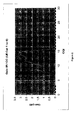
- Figures 2 to 6 illustrate, on an AWGN channel, the gain that can be expected from using Incremental Redundancy (IR) instead of CC for each terminal category group.
- IR Incremental Redundancy
- FIGs 2 to 6 show that using IR systematically instead of CC never degrades performance.
- the performance tests have been completed and are illustrated for a configuration that conforms to the test specification TS 34.108 ("Technical Specification Group Terminals; Common test environments for User Equipment (UE); Conformance Testing", Release 5, v. 5.2.0., published in September 2004, by the 3GPP) with the above-mentioned implicit configuration mode with regard to the memory per process size.
- TS 34.108 Technical Specification Group Terminals; Common test environments for User Equipment (UE); Conformance Testing", Release 5, v. 5.2.0., published in September 2004, by the 3GPP
- CC is a pure repetition mode
- the puncturing or repetition pattern remains the same for all retransmission as the one used for the initial transmission.
- this puncturing or repetition pattern changes each time the block is retransmitted.
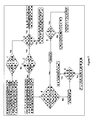
- FIG. 7 a block diagram is shown of a method provided by a preferred embodiment of the invention in the case of a HSDPA transmission.
- the comparison (block 1 on figure 7) of the number of systematic bits to the number of bits to be sent over the air interface comprises a comparison of the overall coding rate (N SYS /N DATA ) to the error correcting encoding rate.
- N SYS /N DATA the overall coding rate
- the number of bits output by the encoder equals n times the number of bits input to the encoder (number of systematic bits).
- the encoding rate is termed turbo coding rate.
- the specified HSDPA turbo coder has a coding rate of 1/3.
- the retransmission scheme in accordance with an embodiment of the present invention comprises:
- the number of bits to be sent over the air interface (N DATA ) is compared to the maximum memory size at the receiver unit available for a HARQ retransmission process (N IR ) (block 2 on figure 7).
- the first stage of the rate matching process will puncture bits up to the maximum memory size at the receiver unit available for a HARQ retransmission process (N IR ) and the second stage will have to repeat some bits to match the number of bits to be sent over the air interface (N DATA ).
- chase combining optionally combined with CoRe for a 16QAM modulation, is applied.
- the selection (block 3 on figure 7) of the rate matching parameters - i.e. the redundancy version vector X RV (i) - that can be used for the retransmissions is then completed on the base of the transmission modulation scheme in the same way as previously described:
- N DATA the number of bits to be sent over the air interface
- N IR the maximum memory size at the receiver unit available for a HARQ retransmission process
- N PUNCT2 N SYS + N P1 + N P2 - N DATA .
- N PUNCT2 This calculated number of parity bits to be punctured by the second stage of the rate matching process (N PUNCT2 ) is compared to the number of bits, exclusive of the number of systematic bits (N SYS ), to be sent over the air interface, i.e. N DATA minus N SYS . - block 4 on figure 7.
- N PUNCT2 If the number of parity bits to be punctured by the second stage of the rate matching process (N PUNCT2 ) is larger than the number of bits, exclusive of the number of systematic bits (N SYS ), to be sent over the air interface, HARQ mode 3 (Full Incremental Redundancy) is selected. Otherwise HARQ mode 2 (Partial Incremental Redundancy) is selected instead.
- the selection (block 6 on figure 7) of the rate matching parameters - i.e. the redundancy version vector X RV (i) - that can be used for the retransmissions is then completed on the base of the transmission modulation scheme:
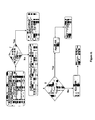
- FIG. 8 a block diagram is shown of method provided by a preferred embodiment of the invention in the case of a HSUPA transmission.
- the comparison (block 7 on figure 8) of the number of systematic bits to the number of bits to be sent over the air interface comprises a comparison of the overall coding rate (N SYS /N DATA ) to the encoding rate.
- the encoding rate is the turbo coding rate, and equals 1/3.
- the redundancy version vector X RV (0) (see table 2bis) is selected for the retransmissions
- an incremental redundancy retransmission scheme is selected.
- HARQ mode 2 i.e. Full Incremental Redundancy (FIR) and HARQ mode 3, i.e. Partial Incremental Redundancy (PIR)
- FIR Full Incremental Redundancy
- PIR Partial Incremental Redundancy
- This calculated number of parity bits to be punctured by the rate matching process is compared to the number of bits, exclusive of the number of systematic bits (N SYS ), to be sent over the air interface, i.e. N DATA minus N SYS . - block 8 on figure 8.
- HARQ mode 3 Full Incremental Redundancy
- HARQ mode 2 Partial Incremental Redundancy
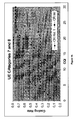
- the five terminal categories groups are considered on figures 9 to 12, respectively, with default memory size N IR values defined as reference in each terminal categories group CQI table.
- Figures 9 to 12 illustrate the coding gain provided by incremental redundancy between the first transmission and the first retransmission.
- the present invention may be implemented in hardware or, for example, in software using a processing engine such as a microprocessor or a programmable logic device (PLD's) such as a PLA (programmable logic array), PAL (programmable array logic), FPGA (field programmable gate array).
- a processing engine such as a microprocessor or a programmable logic device (PLD's) such as a PLA (programmable logic array), PAL (programmable array logic), FPGA (field programmable gate array).
- PLA programmable logic array
- PAL programmable array logic
- FPGA field programmable gate array
- circuit 20 with an embedded processor will be described with reference to Fig. 13 for use in a base station or a mobile radio telephone receiver/transmitter.
- This circuit 20 may be constructed as a VLSI chip around an embedded microprocessor 30 such as an ARM7TDMI core designed by ARM Ltd., UK which may be synthesized onto a single chip with the other components shown.
- a zero wait state SRAM memory 22 may be provided on-chip as well as a cache memory 24.
- Various I/O (input/output) interfaces 25, 26, 27 may be provided, e.g. UART, USB, I 2 C bus interface as well as an I/O selector 28 for receiving data bits from a suitable source, e.g. a data or speech source.
- FIFO buffers 32 may be used to decouple the processor 30 from data transfer through these interfaces.
- a counter/timer block 34 may be provided as well as an interrupt controller 36.
- the interface to the radio frequency part is provided by block 42 which can be used for transmitting to, and receiving from the radio frequency power module 44.
- the block 42 could also handle the multiplexing and demultiplexing of multi-user baseband data. In receive mode, baseband data received by block 42 is passed to the processor 30 for processing.
- Software programs may be stored in an internal ROM (read only memory) 46 and/or may be stored in an external memory. Access to an external memory may be provided an external bus interface 38 with address, data and control busses.
- the various blocks of circuit 20 are linked by suitable busses 31.
- the control mechanisms of the present invention may be implemented as software to run on processor 30.
- a dynamic retransmission mode selector in accordance with the present invention may be implemented by suitable programming of the processor 30.
- the methods and procedures described above may be written as computer programs in a suitable computer language such as C and then compiled for the specific processor in the embedded design.
- the software may be written in C and then compiled using the ARM C compiler and the ARM assembler.
- the software may include code for selecting a retransmission mode.
- the base station of mobile unit has means for the transmission of data over an air interface.
- the base station or mobile unit also has means for the data being processed according to an error correcting encoding scheme prior to transmission over the interface.
- the software code which when executed on a processing engine, includes means for first comparing the number of bits to be encoded (N SYS ) and the number of bits to be sent over the interface (N DATA ); and means for determining, responsive to said first comparison, a type of retransmission mode for the retransmission of the first transmitted data.
- the code may also include means for a second comparing of a number of bits representative of an available memory size at the receiver unit (N IR ) and the number of bits to be sent over the air interface (N DATA ); and means for determining, responsive to said first and second comparisons, a type of retransmission mode for the retransmission of the first transmitted data.
- the software code having means for determining a type of retransmission mode may comprise means determining whether the retransmission of data may be done according to an incremental redundancy scheme.
- the software code for the second comparing may comprise means for a comparison of a number of bits representing a maximum memory size at the receiver unit available for a retransmission process (N IR ), with the number of bits to be sent over the interface (N DATA ).
- the software code having the means for first comparing of the number of bits to be encoded (N SYS ) and the number of bits to be sent over the interface (N DATA ) may comprise means for comparing the overall coding rate (N SYS /N DATA ) to the error correcting encoding rate (1/n).
- the software code for the determining of a type of retransmission mode may comprise means for excluding an incremental redundancy retransmission scheme if the overall coding rate (N SYS /N DATA ) is smaller than the error correcting encoding rate (1/n).
- the software code for the determining of a type of retransmission mode may comprise means for excluding an incremental redundancy retransmission scheme if the overall coding rate (N SYS /N DATA ) is greater than the error correcting encoding rate (1/n) and the number of bits representing a maximum memory size at the receiver unit available for a retransmission process (N IR ) is smaller than the number of bits to be sent over the interface (N DATA ).
- the software code including the means for determining a type of retransmission mode may comprise means for selecting an incremental redundancy retransmission scheme if the overall coding rate (N SYS /N DATA ) is greater than the error correcting encoding rate (1/n) and the number of bits representing a maximum memory size at the receiver unit available for a retransmission process (N IR ) is greater than the number of bits to be sent over the interface (N DATA ).
- the software code may also include means for calculating a number (N PUNCT2 ) of bits to be punctured in order to match the number of bits to be sent over the interface (N DATA ); and means for third comparing the number of bits, exclusive of the number of bits to be encoded, to be sent over the interface (N DATA - N SYS ) and said number (N PUNCT2 ) of bits to be punctured in order to match the number of bits to be sent over the interface (N DATA ); and means for selecting, responsive to said third comparison, an incremental redundancy scheme for the retransmission of the first transmitted data.
- software code may be provided for selecting an incremental redundancy retransmission scheme, for the transmission of data which have been first transmitted in acknowledged mode between a transmitter unit and a receiver unit over an interface, and for which no positive acknowledgement of said first transmission has been received at the transmitter unit, the data being processed according to an error correcting encoding scheme and a rate matching scheme prior to transmission over the interface.
- the software code when executed on a processing engine, has means for determining whether the retransmission of data may be done according to an incremental redundancy retransmission scheme; means for calculating a number (N PUNCT2 ) of bits to be punctured in order to match the number of bits to be sent over the interface (N DATA ); means for comparing the number of bits, exclusive of the number of bits to be encoded, to be sent over the interface (N DATA - N SYS ) and said number (N PUNCT2 ) of bits to be punctured in order to match the number of bits to be sent over the interface (N DATA ); and means for selecting, responsive to said comparison, an incremental redundancy scheme for the retransmission of the first transmitted data.
- the means for selecting of an incremental redundancy scheme for the retransmission of data may comprise means for selecting the Full Incremental Redundancy mode or the Partial Incremental Redundancy Mode.
- the means for selecting of an incremental redundancy scheme for the retransmission of data may comprise means for selecting a predetermined incremental redundancy scheme for the retransmission of data if the number of bits, exclusive of the number of bits to be encoded (N SYS ), to be sent over the interface (N DATA - N SYS ) is smaller than said number (N PUNCT2 ) of bits to be punctured in order to match the number of bits to be sent over the interface (N DATA ).
- the means for selecting an incremental redundancy scheme for the retransmission of data may comprise means for selecting a predetermined incremental redundancy scheme for the retransmission of data if the number of bits, exclusive of the number of bits to be encoded (N SYS ), to be sent over the interface (N DATA - N SYS ) is greater than said number (N PUNCT2 ) of bits to be punctured in order to match the number of bits to be sent over the interface (N DATA ).
- a dynamic retransmission mode selector in accordance with the present invention may be implemented in block 42 which then co-operates with the processor 30 to provide the retransmission mode selection.
- the block 42 includes the means defined above for the software code.
Landscapes
- Engineering & Computer Science (AREA)
- Physics & Mathematics (AREA)
- Probability & Statistics with Applications (AREA)
- Theoretical Computer Science (AREA)
- Computer Networks & Wireless Communication (AREA)
- Signal Processing (AREA)
- Detection And Prevention Of Errors In Transmission (AREA)
Abstract
Description
- The present invention relates to methods and apparatus to provide techniques for transmitting data in acknowledged mode with re-transmission from a sending unit to a receiving unit. It is in particular directed to radiocommunication systems such as wireless telecommunication systems including cellular wireless communication systems.
- In third generation radio communication networks of the UMTS type ("Universal Mobile Telecommunication System") HSDPA ("High Speed Downlink Packet Access") functionality is available. An overall description of the HSDPA functionality can be found in the technical specification TS 25.308,
Release 6, version 6.2.0, published in September 2004 by the 3GPP. - In the UMTS system, a "High Speed Uplink Packet Access" (HSUPA) feature is currently being specified by the 3GPP (3rd Generation Partnership Project) - also named "FDD enhanced uplink" in 3GPP terminology, or "E-DCH" according to the transport channel's name.
- HSDPA allows the transmission, by a base station, of data at high throughput in respect of a set of radio terminals situated in the zone of coverage of a base station. It relies on a time-sharing and code-sharing high-throughput downlink transport channel: the HS-DSCH ("High Speed - Downlink Shared Channel"). UMTS allows a TDD (Time Division Duplex) and an FDD ("Frequency Division Duplex") mode. In the FDD mode, the characteristics of this channel are in particular: (i) a transmission time interval (TTI) of 2 milliseconds corresponding to 3 time slots of 666 µs; (ii) hybrid data retransmission request processes of HARQ type ("Hybrid Automatic Repeat reQuest"); and (iii) an adaptive coding and modulation mechanism.
- HSUPA is a new feature currently being specified by the 3GPP, in order to provide high speed uplink transmission, i.e. from a UE to the access network.
- This service is based on the so-called "E-DCH", a new type of transport channel which also supports hybrid data retransmission request processes of HARQ type, an adaptive coding and modulation mechanism, and base station scheduling of the uplink data transmissions.
- There are 3 main types, or modes, for an HARQ protocol: HARQ in
mode 1 is a pure repetition mode, i.e. the same block is retransmitted. Usually corrupted blocks are discarded by the receiver. A variant consists in memorizing erroneous blocks and combining all retransmissions of a same block together. When optimum combining at the bit level is performed, this has been called Chase Combining (CC) in reference to the technical paper entitled: "Code Combining - A Maximum-Likelihood Decoding Approach for Combining an Arbitrary Number of Noisy Packets" published by David Chase in 1985 (IEEE Trans. Comm. Tech., vol COM-33, No. 5, May 1985). - HARQ in
mode 2 corresponds to Incremental Redundancy (IR). The retransmission of a non self-decodable version of the original block is allowed, i.e. a non self-decodable version cannot be decoded alone. Prior to decoding it, it must be combined with a previously received self-decodable version. In general, optimum combining is performed for bits already transmitted. For retransmissions, priority is given to parity bits, which have been punctured in previous transmission attempts, i.e. systematic bits may be fully punctured if necessary. It is also sometimes called Full IR (FIR) within 3GPP. - HARQ in
mode 3 belongs to the IR family. The difference between both IR types is that an additional constraint is imposed in HARQ oftype 3 redundancy versions. These redundancy versions must be self-decodable, i.e. in the case of turbo encoded data blocks all systematic bits must be transmitted for each retransmission. Optimum combining is performed for bits already transmitted. This is also sometimes called Partial IR (PIR) within 3GPP. - For HSDPA, at the access network level, a specific sublayer of the medium access control protocol, MAC-hs ("Medium Access Control - high speed"), is localized in the base station. This layer receives data originating from the so-called MAC-d sublayer localized, for its part, in the radio network controller RNC on which the base station depends. Thus, matters are arranged such as to offer an optimum throughput on the HS-DSCH channel. For the same reason, the HS-PDSCH uses a relatively low spreading factor, equal to 16. In a given cell and for a given scrambling code, up to 15 HS-PDSCH channels may be established using orthogonal "channelization" codes. Details regarding medium access control may be found in the technical specification TS 25.321,
Release 6, version 6.2.0, published in June 2004 by the 3GPP. - For an HS-DSCH channel, it is necessary to provide one or more specific shared physical control channels called HS-SCCH ("High Speed - Shared Control CHannel"). The signaling information carried by the HS-SCCHs identify the destination terminals of the blocks transmitted on the HS-PDSCHs, and provide them with a certain number of indications useful for the reception of these blocks:
- a transport format and resource indicator (TFRI), giving the information concerning the format of the dynamic part of the HS-DSCH channel, in particular for the modulation scheme employed, and the physical resources allocated ("channelization" codes);
- the information related to the HARQ protocol, in particular the redundancy version, an HARQ process identifier, and an indicator of new data blocks.
- Feedback information is moreover returned by the terminal, in particular for the acknowledgements of the HARQ protocol, for the measurements useful for link adaptation. This information is transmitted by a dedicated uplink resource, on a channel dubbed HS-DPCCH ("High Speed - Dedicated Physical Control Channel"). A link adaptation makes it possible to modify the shaping format of the data to be transmitted as a function of the quality of the radio link. For this purpose, a shaping request based on an estimate of the signal-to-interference ratio of the downlink, called CQI ("Channel Quality Indicator"), is periodically returned to the base station by the terminal. The parameter CQI is coded on 30 levels, the gap between two levels corresponding to a gap of 1 dB in the signal-to-interference ratio.
- Moreover, each terminal can provide the base station under whose radio coverage it finds itself, by way of the RNC, with information concerning its reception capabilities. It thus indicates to the base station in particular:
- whether it supports the two modulations provided for in the system; namely QPSK ("Quadrature Phase Shift Keying") modulation and 16-QAM ("16-Quadrature Amplitude Modulation") modulation, or else just one of them;
- if its memory allows it to receive data at every TTI, or else every n TTI only, with n an integer;
- if its memory allows it to implement all the possible modes of the HARQ protocol (repetition mode, total or partial Incremental Redundancy mode), or else only some of them.
- On setting up the HS-DSCH and HS-SCCHs, the radio network controller which supervises the base station (CRNC, "Controlling RNC") allocates it the corresponding code resources, per cell. By way of example, provision may be made to reserve a list of L = 16 codes with spreading factor 128 for the HS-SCCH channels.
- At each TTI, these resources are distributed among various users for which data are to be transmitted. To do this, an allocation of resources is performed by the MAC-hs sublayer of the base station considered.
- For HSUPA, at the MAC level, a new MAC termination point, the MAC-e, has also been introduced in the UTRAN architecture, and more specifically at the base station level. This architecture is described in the 3GPP TS 25.309 draft specification "Enhanced uplink UTRA FDD;
Stage 2", version 0.2.0, published in July 2004 by the 3GPP. - Current known implementations of the HARQ protocol in the HSDPA feature provide a configuration of the HARQ protocol at the system configuration level. This lacks flexibility and does not optimize the gain of the HARQ protocol scheme.
- An object of the present invention is to provide an enhanced apparatus and a process to limit the abovementioned drawbacks.
- The present invention provides an enhanced apparatus and process by which a retransmission mode is dynamically selected among a plurality of available retransmission modes in accordance with a selection parameter.
- An advantage of the present invention is that rate matching parameters are dynamically configured so as to optimize retransmission gain.
- According to one broad aspect, the invention provides a method of selecting a retransmission mode, for transmission of data which have been first transmitted in acknowledged mode between a transmitter unit and a receiver unit over an interface, and for which no positive acknowledgement of said first transmission has been received at the transmitter unit, the data being processed according to an error detection encoding scheme or an error correcting encoding scheme prior to transmission over the interface, the method comprising:
- first comparing the number of bits to be encoded (NSYS) and the number of bits to be sent over the interface (NDATA), and
- determining, responsive to said first comparison, a type of retransmission mode for the retransmission of the first transmitted data.
- In some embodiments, the method further comprises a second comparison of a number of bits representative of an available memory size at the receiver unit (NIR) and the number of bits to be sent over the air interface (NDATA), and determining, responsive to said first and second comparisons, a type of retransmission mode for the retransmission of the first transmitted data.
- In some embodiments, determining of the retransmissison type can comprise determining whether the retransmission of data may be done according to an incremental redundancy scheme.
- In some embodiments, the second comparison comprises a comparison of a number of bits representing a maximum memory size at the receiver unit available for a retransmission process (NIR), with the number of bits to be sent over the interface (NDATA).
- In some embodiments, the first comparison of the number of bits to be encoded (NSYS) and the number of bits to be sent over the interface (NDATA) comprises:
- comparing an overall coding rate (NSYS/NDATA) to an error correcting encoding rate.
- In some embodiments, determining a type of retransmission mode comprises:
- excluding an incremental redundancy retransmission scheme if an overall coding rate (NSYS/NDATA) is smaller than an error correcting encoding rate.
- In some embodiments, determining a type of retransmission mode comprises:
- excluding an incremental redundancy retransmissionscheme if an overall coding rate (NSYS/NDATA) is greater than an error correcting encoding rate and the number of bits representing a maximum memory size at the receiver unit available for a retransmission process (NIR) is smaller than the number of bits to be sent over the interface (NDATA).
- In some embodiments, determining a type of retransmission mode comprises:
- selecting an incremental redundancy retransmission scheme if an overall coding rate (NSYS/NDATA) is greater than an error correcting encoding rate and the number of bits representing a maximum memory size at the receiver unit available for a retransmission process (NIR) is greater than the number of bits to be sent over the interface (NDATA).
- In some embodiments, the error correcting scheme is turbo coding, and the error correcting encoding rate equals 1/3.
- Another broad aspect provides a method for transmitting data over an interface, the data being processed according to an error correcting encoding scheme and a rate matching scheme prior to transmission over the interface, further comprising the steps of calculating a number (NPUNCT2) of bits to be punctured in order to match the number of bits to be sent over the interface (NDATA), a third comparison of the number of bits, exclusive of the number of bits to be encoded, to be sent over the interface (NDATA - NSYS) and said number (NPUNCT2) of bits to be punctured in order to match the number of bits to be sent over the interface (NDATA) and selecting, responsive to said third comparison, an incremental redundancy scheme for the retransmission of the first transmitted data.
- Another broad aspect provides a method of selecting an incremental redundancy retransmission scheme, for the transmission of data which have been first transmitted in acknowledged mode between a transmitter unit and a receiver unit over an interface, and for which no positive acknowledgement of said first transmission has been received at the transmitter unit, the data being processed according to an error correcting encoding scheme or an error detection encoding scheme and a rate matching scheme prior to transmission over the interface, the method comprising the steps of determining whether the retransmission of data may be done according to an incremental redundancy retransmission scheme, calculating a number (NPUNCT2) of bits to be punctured in order to match the number of bits to be sent over the interface (NDATA), comparing the number of bits, exclusive of the number of bits to be encoded, to be sent over the interface (NDATA - NSYS) and said number (NPUNCT2) of bits to be punctured in order to match the number of bits to be sent over the interface (NDATA) and selecting, responsive to said comparison, an incremental redundancy scheme for the retransmission of the first transmitted data.
- In some embodiments, the selecting of an incremental redundancy scheme for the retransmission of data comprises: selecting a Full Incremental Redundancy mode or a Partial Incremental Redundancy Mode.
- In some embodiments, the selecting of an incremental redundancy scheme for the retransmission of data, comprises selecting a predetermined incremental redundancy scheme for the retransmission of data if the number of bits, exclusive of the number of bits to be encoded (NSYS), to be sent over the interface (NDATA - NSYS) is smaller than said number (NPUNCT2) of bits to be punctured in order to match the number of bits to be sent over the interface (NDATA).
- In some embodiments, said selected predetermined incremental redundancy scheme is Full Incremental Redundancy.
- In some embodiments, the selecting of an incremental redundancy scheme for the retransmission of data, comprises selecting a predetermined incremental redundancy scheme for the retransmission of data if the number of bits, exclusive of the number of bits to be encoded (NSYS), to be sent over the interface (NDATA - NSYS) is greater than said number (NPUNCT2) of bits to be punctured in order to match the number of bits to be sent over the interface (NDATA).
- In some embodiments, selected predetermined incremental redundancy scheme is Partial Incremental Redundancy.
- Another broad aspect provides a retransmission mode selector adapted to implement the above-mentioned methods. Another broad aspect provides an incremental redundancy retransmission scheme selector, adapted to implement some of the above-mentioned methods.
- A dynamic retransmission mode selector in accordance with the present invention is adapted for selecting a retransmission mode, for the transmission of data which have been first transmitted in acknowledged mode between a transmitter unit and a receiver unit over an interface, and for which no positive acknowledgement of said first transmission has been received at the transmitter unit, the data being processed according to an error correcting encoding scheme prior to transmission over the interface. The selector includes means for first comparing the number of bits to be encoded (NSYS) and the number of bits to be sent over the interface (NDATA); and means for determining, responsive to said first comparison, a type of retransmission mode for the retransmission of the first transmitted data. The selector may also include means for a second comparing of a number of bits representative of an available memory size at the receiver unit (NIR) and the number of bits to be sent over the air interface (NDATA); and means for determining, responsive to said first and second comparisons, a type of retransmission mode for the retransmission of the first transmitted data. In the selector the means for determining a type of retransmission mode may comprise means determining whether the retransmission of data may be done according to an incremental redundancy scheme. In the selector the means for the second comparing may comprise means for a comparison of a number of bits representing a maximum memory size at the receiver unit available for a retransmission process (NIR), with the number of bits to be sent over the interface (NDATA). In the selector the means for first comparing of the number of bits to be encoded (NSYS) and the number of bits to be sent over the interface (NDATA) may comprise means for comparing the overall coding rate (NSYS/NDATA) to the error correcting encoding rate (1/n). In the selector the means for determining of a type of retransmission mode may comprise means for excluding an incremental redundancy retransmission scheme if the overall coding rate (NSYS/NDATA) is smaller than the error correcting encoding rate (1/n).
In the selector, the means for determining of a type of retransmission mode may comprise means for excluding an incremental redundancy retransmission scheme if the overall coding rate (NSYS/NDATA) is greater than the error correcting encoding rate (1/n) and the number of bits representing a maximum memory size at the receiver unit available for a retransmission process (NIR) is smaller than the number of bits to be sent over the interface (NDATA). In the selector the means for determining a type of retransmission mode may comprise means for selecting an incremental redundancy retransmission scheme if the overall coding rate (NSYS/NDATA) is greater than the error correcting encoding rate (1/n) and the number of bits representing a maximum memory size at the receiver unit available for a retransmission process (NIR) is greater than the number of bits to be sent over the interface (NDATA).
In a further aspect of the present invention retransmission mode selector is provided when the transmitted data is processed according to an error correcting encoding scheme and a rate matching scheme prior to transmission over the interface, the selector including means for calculating a number (NPUNCT2) of bits to be punctured in order to match the number of bits to be sent over the interface (NDATA); and means for third comparing the number of bits, exclusive of the number of bits to be encoded, to be sent over the interface (NDATA - NSYS) and said number (NPUNCT2) of bits to be punctured in order to match the number of bits to be sent over the interface (NDATA); and means for selecting, responsive to said third comparison, an incremental redundancy scheme for the retransmission of the first transmitted data. - The present invention also provides a dynamic retransmission selector for selecting an incremental redundancy retransmission scheme, for the transmission of data which have been first transmitted in acknowledged mode between a transmitter unit and a receiver unit over an interface, and for which no positive acknowledgement of said first transmission has been received at the transmitter unit, the data being processed according to an error correcting encoding scheme and a rate matching scheme prior to transmission over the interface. The selector has means for determining whether the retransmission of data may be done according to an incremental redundancy retransmission scheme; means for calculating a number (NPUNCT2) of bits to be punctured in order to match the number of bits to be sent over the interface (NDATA); means for comparing the number of bits, exclusive of the number of bits to be encoded, to be sent over the interface (NDATA - NSYS) and said number (NPUNCT2) of bits to be punctured in order to match the number of bits to be sent over the interface (NDATA); and means for selecting, responsive to said comparison, an incremental redundancy scheme for the retransmission of the first transmitted data. The means for selecting of an incremental redundancy scheme for the retransmission of data may comprise means for selecting the Full Incremental Redundancy mode or the Partial Incremental Redundancy Mode. The means for selecting of an incremental redundancy scheme for the retransmission of data, may comprise means for selecting a predetermined incremental redundancy scheme for the retransmission of data if the number of bits, exclusive of the number of bits to be encoded (NSYS), to be sent over the interface (NDATA - NSYS) is smaller than said number (NPUNCT2) of bits to be punctured in order to match the number of bits to be sent over the interface (NDATA). The means for selecting an incremental redundancy scheme for the retransmission of data, may comprise means for selecting a predetermined incremental redundancy scheme for the retransmission of data if the number of bits, exclusive of the number of bits to be encoded (NSYS), to be sent over the interface (NDATA - NSYS) is greater than said number (NPUNCT2) of bits to be punctured in order to match the number of bits to be sent over the interface (NDATA).
- Another broad aspect provides a computer readable medium having processor executable instructions thereon for implementation by a processor, the instructions executing any of the above-mentioned methods.
- Another broad aspect provides a signal processing apparatus, e.g. for use in a transmitter unit adapted to transmit data to a receiver unit in acknowledged mode over an interface, the signal processing apparatus comprising, for the transmission of data which have been first transmitted between said transmitter unit and a receiver unit over an interface, and for which no positive acknowledgement of said first transmission has been received at the transmitter unit, the data being processed according to an error correcting encoding scheme prior to transmission over the interface, first comparator means, for first comparing of the number of bits to be encoded (NSYS) and the number of bits to be sent over the interface and first control means, for determining, responsive to said first comparison, a type of retransmission mode for the retransmission of the first transmitted data.
- In some embodiments, the signal processing apparatus further comprises second comparator means for second comparing of a number of bits representative of an available memory size at the receiver unit (NIR) and the number of bits to be sent over the air interface (NDATA) and second control means, for determining, responsive to said first and second comparisons, a type of retransmission mode for the retransmission of the first transmitted data.
- In some embodiments, said first comparator means of the signal processing apparatus are adapted to compare the overall coding rate (NSYS/NDATA) with the error correcting encoding rate.
- Another broad aspect provides a signal processing apparatus, e.g. in a transmitter unit adapted to transmit data to a receiver unit in acknowledged mode over an interface, the signal processing apparatus comprising, for the transmission of data which have been first transmitted between said transmitter unit and a receiver unit over an interface, and for which no positive acknowledgement of said first transmission has been received at the transmitter unit, the data being processed according to an error correcting encoding scheme and a rate matching scheme prior to transmission over the interface, means for determining whether the retransmission of data may be done according to an incremental redundancy retransmission scheme, means for calculating a number (NPUNCT2) of bits to be punctured in order to match the number of bits to be sent over the interface (NDATA), means for comparing the number of bits, exclusive of the number of bits to be encoded, to be sent over the interface (NDATA - NSYS) and said number (NPUNCT2) of bits to be punctured in order to match the number of bits to be sent over the interface (NDATA), means for selecting, responsive to said comparison, an incremental redundancy scheme for the retransmission of the first transmitted data.
- Another broad aspect provides a base station comprising a signal processing apparatus as mentioned above.
- Another broad aspect provides a mobile terminal comprising a signal processing apparatus as mentioned above.
-
- Figure 1 is a diagram representing the HSDPA double stage rate matching process as specified by the 3GPP;
- Figure 2 is a curve illustrating the gain of Incremental Redundancy when compared to Chase Combining for terminals of
categories 1 to 6; - Figure 3 is a curve illustrating the gain of Incremental Redundancy when compared to Chase Combining for terminals of
categories - Figure 4 is a curve illustrating the gain of Incremental Redundancy when compared to Chase Combining for terminals of
category 9; - Figure 5 is a curve illustrating the gain of Incremental Redundancy when compared to Chase Combining for terminals of
category 10; - Figure 6 is a curve illustrating the gain of Incremental Redundancy when compared to Chase Combining for terminals of
categories - Figure 7 is a block diagram of a method provided by a preferred embodiment of the invention in the case of a HSDPA transmission;
- Figure 8 is a block diagram of a method provided by a preferred embodiment of the invention in the case of a HSUPA transmission;
- Figure 9 is a curve illustrating the coding rate gain of Incremental Redundancy versus Chase combining between the first transmission tentative and the first retransmission, for terminals of
category 9; - Figure 10 is a curve illustrating the coding rate gain of Incremental Redundancy versus Chase combining between the first transmission tentative and the first retransmission, for terminals of
categories - Figure 11 is a curve illustrating the coding rate gain of Incremental Redundancy versus Chase combining between the first transmission tentative and the first retransmission, for terminals of
category 10; - Figure 12 is a curve illustrating the coding rate gain of Incremental Redundancy versus Chase combining between the first transmission tentative and the first retransmission, for terminals of
categories - Figure 13 is schematic diagram of an implementation of an embodiment of the present invention.
- The present invention will be described with respect to particular embodiments and with reference to certain drawings but the invention is not limited thereto but only by the claims. The drawings described are only schematic and are non-limiting. In the drawings, the size of some of the elements may be exaggerated and not drawn on scale for illustrative purposes. Where the term "comprising" is used in the present description and claims, it does not exclude other elements or steps. Furthermore, the terms first, second, third and the like in the description and in the claims, are used for distinguishing between similar elements and not necessarily for describing a sequential or chronological order. It is to be understood that the terms so used are interchangeable under appropriate circumstances and that the embodiments of the invention described herein are capable of operation in other sequences than described or illustrated herein.
- For purposes of example only, the present invention will be described more particularly in its application, non-limiting, to third generation radio communication networks of the UMTS type ("Universal Mobile Telecommunication System"). It will be described herein below within the context of the HSDPA ("High Speed Downlink Packet Access") functionality, available in the UMTS ("Universal Mobile Telecommunication System") radiocommunication system, without thereby restricting the generality of its subject matter. An overall description of the HSDPA functionality can be found in the technical specification TS 25.308,
Release 6, version 6.2.0, published in September 2004 by the 3GPP. - In the UMTS system, the invention also finds application for example, within the framework of the "High Speed Uplink Packet Access" (HSUPA) feature currently being specified by the 3GPP (3rd Generation Partnership Project) - also named "FDD enhanced uplink" in 3GPP terminology, or "E-DCH" according to the transport channel's name.
- The
3GPP release 5 rate matching algorithm is described in the specification TS 25.212, "Multiplexing and Channel Coding (FDD)",Release 5, version 5.9.0, published in June 2004 by the 3GPP. The rate matching is described in section 4.2.7 of this specification, which is incorporated herein by reference. This algorithm features a double stage rate matching process as illustrated in figure 1 (first rate matching 4 and second rate matching 6). - The
rate matching function 1 performs either puncturing or repetition, depending on the number of bits to be transmitted over the air interface (hereinafter NDATA) and depending on the number of coded bits provided by the channel encoder (systematic bits, 1st parity bits and 2nd parity bits streams). - The bits input to the
rate matching function 1 are separated into three different streams in thebit separation module 2. The first stream contains systematic bits, i.e. the unencoded information bits, or, said differently, the number of bits to be encoded. The second one contains the parity bits provided by the first constituent code of a turbo encoder and the third one contains parity bits generated by the second constituent code of the turbo encoder. This operation is done by the bit separation function in the rate matching. - The first
rate matching stage 4 can only perform bit puncturing, and only on both parity bits streams. The first systematic bits stream remains unchanged. Its goal is to ensure that the coded block size with which the secondrate matching stage 6 can operate, matches the memory size available at the terminal for one HARQ process, indicated by higher layers as NIR. With reference to the virtual IR buffer this means that NIR ≥ Nsys + Np1 + Np2. - Once the first
rate matching stage 4 has generated bits, the secondrate matching stage 6 can either puncture or repeat depending on the number of bits collected in thecollector 8 and to be sent over the air interface (Ndata). - The second
rate matching stage 6 generates different versions, called "redundancy versions" (RV), of bit vectors in its input based on rate matching (puncturing or repetition) parameters. Said parameters of the second rate matching stage, denoted s, r and b, are grouped to form so-called XRV vectors as listed in tables 1 and 2 below. Xrv also serves as a control parameter transmitted by the network to the HSDPA terminals that identifies a redundancy version, that is to say the set of rate matching parameters that a HSDPA terminal shall use for the coding and rate matching processing of the bits that it will receive as part of the HSDPA communication. - ■ The parameter s can take the
value value 1 the systematic bits cannot be punctured, whereas if s is set to 0, the systematic bits can be punctured. - ■ The parameter r (which ranges from 0 to rmax-1) changes the initial error variable eini of the rate matching algorithm in the case of puncturing. eini is a configuration parameter in the rate matching algorithm described in the above-mentioned TS 25.212 3GPP specification. It influences the puncturing pattern starting position as well as the bit puncturing frequency in the pattern.
- ■ A third parameter, b, is used for an additional performance enhancement functionality called constellation re-arrangement (CoRe), but only when the 16QAM modulation scheme is used. It consists in rotating 16QAM constellation for balancing so-called Log Likelihood Ratio's (LLR) amplitudes.
- The interest of having different puncturing patterns, each generating a redundancy version, is that when retransmissions are combined at the receiver together with the initial transmission, the coding rate is reduced because of the additional redundancy brought by subsequent retransmissions. Therefore a better error correction capability is provided to the decoder.
- Tables 1 and 2 below provide examples of the composition of a set of 8 XRV vectors, in the case of a 16QAM modulation, and in the case of a QPSK modulation, respectively.
Table 1: redundancy versions for 16QAM X RV s R b 0 1 0 0 1 0 0 0 2 1 1 1 3 0 1 1 4 1 0 2 5 1 0 2 6 1 0 3 7 1 1 0 Table 2: redundancy versions for QPSK X RV s R 0 1 0 1 0 0 2 1 1 3 0 1 4 1 2 5 0 2 6 1 3 7 0 3 - Now referring to Figure 1, NSYS is the number of systematic bits, i.e. the number of bits to be encoded, Np1 and Np2 are the number of parity bits in parity bits stream at the output of the first rate matching stage 4 (issued respectively by the first and the second constituent codes of the turbo encoder). Finally, Nt,sys corresponds to the number of systematic bits after the second
rate matching stage 6, Nt,p1 to the number ofparity 1 bits after the secondrate matching stage 6 and Nt,p2 to the number ofparity 2 bits after the secondrate matching stage 6. - The output of the first
rate matching stage 4 is preferably the minimum between the sum of Nsys, Np1 and Np2 and NIR, i.e. Nout_RM1 = min(NIR, Nsys + Np1 + Np2), as it cannot exceed the size of the terminal memory for the selected HARQ process. - The
3GPP release 6 rate matching algorithm for HSUPA (also called Enhanced Uplink) is described in the technical report TR 25.808, "FDD Enhanced Uplink, Physical Layer Aspects",Release 6, version 0.2.1, published in October 2004 by the 3GPP. The rate matching algorithm comprises a single stage. - The rate matching function performs either puncturing or repetition, depending on the number of bits to be transmitted over the air interface and depending on the number of coded bits provided by the channel encoder (systematic bits, 1st parity bits and 2nd parity bits streams).
- In a similar way to HSDPA, the HSUPA rate matching function generates different versions, also called "redundancy versions" (RV), of bit vectors in its input based on rate matching (puncturing or repetition) parameters. Said parameters of the rate matching, also denoted s and r, are grouped to form XRV vectors as listed in the table 2bis below. Xrv also serves as a control parameter transmitted by the network to the HSUPA terminals that identifies a redundancy version, that is to say the set of rate matching parameters that a HSUPA terminal shall use for the coding and rate matching processing of the bits that it will send as part of the HSUPA communication.
- Table 2bis below provides examples of the composition of a set of 4 XRV redundancy version vectors. The parameters s and r have the same meaning as what is described above for the QPSK modulation.
Table 2bis: redundancy versions for HSUPA X RV s R 0 1 0 1 0 0 2 1 1 3 0 2 - There are 12 HSDPA terminal categories defined in the HSDPA system. These categories can be grouped into 5 pools according to the maximum configuration (modulation and number of spreading codes) they support:
- *
Categories 1 to 6 (5 codes and 16QAM) - *
Categories 7 and 8 (10 codes and 16QAM) - * Category 9 (12 codes and 16QAM)
- * Category 10 (15 codes and 16QAM)
- *
Categories 11 and 12 (5 codes and QPSK only) - For each terminal category group, categories are differentiated by their amount of memory dedicated to HSDPA, as summarized in the following table (and described in the specification TS 25.306, "UE Radio Access Capabilities", v.6.2.0,
Release 6, published in June 2004 by the 3GPP):Table 3: Terminal categories characteristics Terminal category Maximum number of bits of an HS-DSCH transport block at the encoder input (Nsysmax) Total number of soft channel bits Category 1 7298 19200 Category 27298 28800 Category 37298 28800 Category 47298 38400 Category 57298 57600 Category 67298 67200 Category 714411 115200 Category 814411 134400 Category 920251 172800 Category 1027952 172800 Category 113630 14400 Category 123630 28800 - Table 3 contains, for each category, the total amount of memory (total number of soft channel bits) and the maximum size of transport block that can be received i.e. the maximum number of bits at the encoder input.
- For an HSDPA session, a maximum of 8 parallel HARQ processes can be configured. One process is a transmission context for a single transport block at a time. In a so-called implicit configuration mode, the memory per process size is uniform among all retransmission processes. For instance, the memory per process corresponds to the total memory of the terminal divided by the number of active processes configured by the UTRAN. A
category 5 terminal has a total memory size of 57600 soft channel bits (between a rake receiver and a turbo decoder). With 6 processes configured (which corresponds to the optimal theoretical number of transmission contexts needed in order for a continuous transmission), the memory per process is equal to 9600 bits. This memory per process size corresponds to the NIR value that represents the maximum memory size at the terminal available for a HARQ retransmission process. In a so-called explicit configuration mode, this maximum memory size can be specific to each configured retransmission process, so that it is not necessarily the same for every retransmission process for the HSDPA communication(s) in which a terminal is involved. - As mentioned above, each terminal can indicate to the base station under whose radio coverage it finds itself, by way of the RNC, information concerning its maximum memory size at the terminal available for a HARQ retransmission process. The terminal indicates to the base station its category, from which the base station selects the maximum number of retransmission processes. This number is then relayed to the RNC and confirmed by the RNC to the base station and the terminal. The base station can then determine the maximum memory size at the terminal available for each retransmission process with the terminal.
- Tables 4 to 8 are CQI tables for the 5 UE categories groups defined above (see the specification TS 25.214, "Physical Layer Procedures (FDD)", v.5.9.0,
Release 5, published by the 3GPP in June 2004). As mentioned above, the CQI indication is periodically transmitted to the base station by the terminal. With each value of CQI is associated a data shaping format, comprising a modulation scheme, a number of spreading codes that can be received simultaneously by the terminal in a TTI, the size of the information block. The base station can derive from information received from a terminal the number of bits to be sent over the air interface parameter (NDATA). For instance, for a QPSK modulation scheme, NDATA = 960 x number of spreading codes(which is a function of the CQI), and for a 16QAM modulation scheme, NDATA = 1920 x number of spreading codes(which is a function of the CQI). - In tables 4 to 8, the value NIR and Xrv represent the default value of the maximum memory size at the terminal available for a HARQ retransmission process, and the redundancy version vector index, respectively, that the terminal uses when estimating the CQI to be returned to the base station.
- According to one aspect of the invention, to each CQI returned by the terminal there corresponds a preferred or selected HARQ mode, as well as a preferred set of rate-matching parameters. The selection of the preferred set of rate matching parameters is especially important for the first retransmission.
Table 4: CQI table for terminal categories 1 to 6 CQI value Transport Block Size Number of Spreading Codes Modulation NIR XRV 0 N/A Out of range 1 137 1 QPSK 9600 0 2 173 1 QPSK 3 233 1 QPSK 4 317 1 QPSK 5 377 1 QPSK 6 461 1 QPSK 7 650 2 QPSK 8 792 2 QPSK 9 931 2 QPSK 10 1262 3 QPSK 11 1483 3 QPSK 12 1742 3 QPSK 13 2279 4 QPSK 14 2583 4 QPSK 15 3319 5 QPSK 16 3565 5 16-QAM 17 4189 5 16-QAM 18 4664 5 16-QAM 19 5287 5 16-QAM 20 5887 5 16-QAM 21 6554 5 16-QAM 22 7168 5 16-QAM 23 7168 5 16-QAM 24 7168 5 16-QAM 25 7168 5 16-QAM 26 7168 5 16-QAM 27 7168 5 16-QAM 28 7168 5 16-QAM 29 7168 5 16-QAM 30 7168 5 16-QAM Table 5: CQI table for terminal categories 7 and 8 CQI value Transport Block Size Number of Spreading Codes Modulation NIR XRV 0 N/A Out of range 1 137 1 QPSK 19200 0 2 173 1 QPSK 3 233 1 QPSK 4 317 1 QPSK 5 377 1 QPSK 6 461 1 QPSK 7 650 2 QPSK 8 792 2 QPSK 9 931 2 QPSK 10 1262 3 QPSK 11 1483 3 QPSK 12 1742 3 QPSK 13 2279 4 QPSK 14 2583 4 QPSK 15 3319 5 QPSK 16 3565 5 16-QAM 17 4189 5 16-QAM 18 4664 5 16-QAM 19 5287 5 16-QAM 20 5887 5 16-QAM 21 6554 5 16-QAM 22 7168 5 16-QAM 23 9719 7 16-QAM 24 11418 8 16-QAM 25 14411 10 16-QAM 26 14411 10 16-QAM 27 14411 10 16-QAM 28 14411 10 16-QAM 29 14411 10 16-QAM 30 14411 10 16-QAM Table 6: CQI table for terminal category 9 CQI value Transport Block Size Number of Spreading Modulation NIR XRV 0 N/A Out of range 1 137 1 QPSK 28800 0 2 173 1 QPSK 3 233 1 QPSK 4 317 1 QPSK 5 377 1 QPSK 6 461 1 QPSK 7 650 2 QPSK 8 792 2 QPSK 9 931 2 QPSK 10 1262 3 QPSK 11 1483 3 QPSK 12 1742 3 QPSK 13 2279 4 QPSK 14 2583 4 QPSK 15 3319 5 QPSK 16 3565 5 16-QAM 17 4189 5 16-QAM 18 4664 5 16-QAM 19 5287 5 16-QAM 20 5887 5 16-QAM 21 6554 5 16-QAM 22 7168 5 16-QAM 23 9719 7 16-QAM 24 11418 8 16-QAM 25 14411 10 16-QAM 26 17237 12 16-QAM 27 17237 12 16-QAM 28 17237 12 16-QAM 29 17237 12 16-QAM 30 17237 12 16-QAM Table 7: CQI table for terminal category 10 CQI value Transport Block Size Number of Spreading Codes Modulation NIR XRV 0 N/A Out of range 1 137 1 QPSK 28800 0 2 173 1 QPSK 3 233 1 QPSK 4 317 1 QPSK 5 377 1 QPSK 6 461 1 QPSK 7 650 2 QPSK 8 792 2 QPSK 9 931 2 QPSK 10 1262 3 QPSK 11 1483 3 QPSK 12 1742 3 QPSK 13 2279 4 QPSK 14 2583 4 QPSK 15 3319 5 QPSK 16 3565 5 16-QAM 17 4189 5 16-QAM 18 4664 5 16-QAM 19 5287 5 16-QAM 20 5887 5 16-QAM 21 6554 5 16-QAM 22 7168 5 16-QAM 23 9719 7 16-QAM 24 11418 8 16-QAM 25 14411 10 16-QAM 26 17237 12 16-QAM 27 21754 15 16-QAM 28 23370 15 16-QAM 29 24222 15 16-QAM 30 25558 15 16-QAM Table 8: CQI table for terminal categories 11 and 12 CQI value Transport Block Size Number of Spreading Codes Modula tion NIR XRV 0 N/A Out of range 1 137 1 QPSK 4800 0 2 173 1 QPSK 3 233 1 QPSK 4 317 1 QPSK 5 377 1 QPSK 6 461 1 QPSK 7 650 2 QPSK 8 792 2 QPSK 9 931 2 QPSK 10 1262 3 QPSK 11 1483 3 QPSK 12 1742 3 QPSK 13 2279 4 QPSK 14 2583 4 QPSK 15 3319 5 QPSK 16 3319 5 QPSK 17 3319 5 QPSK 18 3319 5 QPSK 19 3319 5 QPSK 20 3319 5 QPSK 21 3319 5 QPSK 22 3319 5 QPSK 23 3319 5 QPSK 24 3319 5 QPSK 25 3319 5 QPSK 26 3319 5 QPSK 27 3319 5 QPSK 28 3319 5 QPSK 29 3319 5 QPSK 30 3319 5 QPSK - The default HARQ type specified in the HSDPA technical specification is Chase Combining (CC), i.e. a pure repetition mode with optimum combination of retransmissions by the terminal.
- Figures 2 to 6 illustrate, on an AWGN channel, the gain that can be expected from using Incremental Redundancy (IR) instead of CC for each terminal category group. As depicted in Figures 2 to 6, IR can bring an important performance improvement for some CQI, but is useless for others compared to CC. These figures also show that using IR systematically instead of CC never degrades performance. The performance tests have been completed and are illustrated for a configuration that conforms to the test specification TS 34.108 ("Technical Specification Group Terminals; Common test environments for User Equipment (UE); Conformance Testing",
Release 5, v. 5.2.0., published in September 2004, by the 3GPP) with the above-mentioned implicit configuration mode with regard to the memory per process size. - On the contrary, when IR does not bring any gain, CPU resources can be saved at the base station by configuring CC instead of IR. As CC is a pure repetition mode, the puncturing or repetition pattern remains the same for all retransmission as the one used for the initial transmission. With IR, this puncturing or repetition pattern changes each time the block is retransmitted.
- This clearly illustrates how advantageous a dynamic retransmission mode selection method can be over a static, or preconfigured one.
- Referring now to Figure 7, a block diagram is shown of a method provided by a preferred embodiment of the invention in the case of a HSDPA transmission.
- It is assumed that a negative acknowledgment has been received for data which shall therefore have to be retransmitted according to a retransmission mode. This data will have been transmitted using a redundancy version vector. Typically, such data was first transmitted using the redundancy version vector Xrv(0) by default.
- The comparison (block 1 on figure 7) of the number of systematic bits to the number of bits to be sent over the air interface comprises a comparison of the overall coding rate (NSYS/NDATA) to the error correcting encoding rate. With a 1/n error correcting encoding rate, the number of bits output by the encoder equals n times the number of bits input to the encoder (number of systematic bits). In a case where the error correcting scheme is turbo coding, the encoding rate is termed turbo coding rate. The specified HSDPA turbo coder has a coding rate of 1/3.
- If the overall coding rate is smaller than the turbo code rate, repetition has to be performed by the second stage of the rate matching process and chase combining, possibly combined with CoRe for a 16QAM modulation, is applied. The selection (block 3 on figure 7) of the rate matching parameters - i.e. the redundancy version vector XRV(i) - that can be used for the retransmissions is then completed on the base of the transmission modulation scheme. The retransmission scheme in accordance with an embodiment of the present invention comprises:
- if the transmission modulation scheme is QPSK, only XRV(0) for QPSK (see table 1) will be used, that is s = 1, r = 0;
- if the transmission modulation scheme is 16QAM, only XRV(0), XRV(4), XRV(5), XRV(6) for 16QAM (see table 2) will be used, that is (s=1, r=0, b=0), (s=1, r=0, b=1), (s=1, r=0, b=2) or (s=1, r=0, b=3), respectively. For these 4 sets of rate matching parameters, the parameters s and r of the second stage of the rate matching process have the same values, 1 and 0 respectively. The four corresponding redundancy versions differ in the constellation rotation index, coded in the CoRe parameter b. Therefore the first two parameters, s and r, are set to the same values as for a QPSK transmission modulation scheme, and the difference with QPSK is the availability with 16QAM of the CoRe scheme which provides an additional improvement to the overall performances.
- If the overall coding rate is not smaller than the turbo code rate, the number of bits to be sent over the air interface (NDATA) is compared to the maximum memory size at the receiver unit available for a HARQ retransmission process (NIR) (block 2 on figure 7).
- If the number of bits to be sent over the air interface (NDATA) is greater than the maximum memory size at the receiver unit available for a HARQ retransmission process (NIR), the first stage of the rate matching process will puncture bits up to the maximum memory size at the receiver unit available for a HARQ retransmission process (NIR) and the second stage will have to repeat some bits to match the number of bits to be sent over the air interface (NDATA). In such case chase combining, optionally combined with CoRe for a 16QAM modulation, is applied. The selection (block 3 on figure 7) of the rate matching parameters - i.e. the redundancy version vector XRV(i) - that can be used for the retransmissions is then completed on the base of the transmission modulation scheme in the same way as previously described:
- if the transmission modulation scheme is QPSK, only XRV(0) for QPSK (see table 1) will be used, that is s = 1, r = 0. Alternatively, assuming that the data to be retransmitted would have been first transmitted using the redundancy version vector Xrv(i), where i=2, 4 or 6, the same redundancy version vector as the initial one could be used for the retransmissions. The main requirement is to use only one redundancy version for the first and successive transmissions for which s=1;
- if the transmission modulation scheme is 16QAM, only XRV(0), XRV(4), XRV(5), XRV(6) for 16QAM (see table 2) will be used, that is (s=1, r=0, b=0), (s=1, r=0, b=1), (s=1, r=0, b=2) or (s=1, r=0, b=3), respectively. For these 4 sets of rate matching parameters, the parameters s and r of the second stage of the rate matching process have the same values, 1 and 0 respectively. The four corresponding redundancy versions differ in the constellation rotation index, coded in the CoRe parameter b. Therefore the first two parameters, s and r, are set to the same values as for a QPSK transmission modulation scheme, and the difference with QPSK is the availability with 16QAM of the CoRe scheme which provides an additional improvement to the overall performances. Alternatively, assuming that the data to be retransmitted would have been first transmitted using the redundancy version vector Xrv(i), where i=2 or 7, the same redundancy version vector as the initial one could be used for the retransmissions.
- If the overall coding rate is not smaller than the turbo code rate, and the number of bits to be sent over the air interface (NDATA) is not greater than the maximum memory size at the receiver unit available for a HARQ retransmission process (NIR), an incremental redundancy retransmission scheme is selected.
- In order to complete such selection between
HARQ mode 2, i.e. Full Incremental Redundancy (FIR) andHARQ mode 3, i.e. Partial Incremental Redundancy (PIR), the number of bits to be punctured by the second stage of the HSDPA rate matching process (NPUNCT2) is calculated: NPUNCT2 = NSYS + NP1 + NP2 - NDATA. - This calculated number of parity bits to be punctured by the second stage of the rate matching process (NPUNCT2) is compared to the number of bits, exclusive of the number of systematic bits (NSYS), to be sent over the air interface, i.e. NDATA minus NSYS. -
block 4 on figure 7. - If the number of parity bits to be punctured by the second stage of the rate matching process (NPUNCT2) is larger than the number of bits, exclusive of the number of systematic bits (NSYS), to be sent over the air interface, HARQ mode 3 (Full Incremental Redundancy) is selected. Otherwise HARQ mode 2 (Partial Incremental Redundancy) is selected instead.
- In the case of Full Incremental Redundancy (FIR) selection:
- Any redundancy version may be used, and the full set of redundancy vectors XRV(i), i = 0 to 7 that corresponds to the transmission modulation scheme is available (block 5 on figure 7). Furthermore, preferred sets of rate matching parameters (indicated in bold on Figure 7) are identified for the first retransmission.
- if the transmission modulation scheme is QPSK, the preferred sets are XRV(1), XRV(3), XRV(5) and XRV(7), that is (s=0, r=0), (s=0, r=1), (s=0, r=2) and (s=0, r=3), respectively;
- if the transmission modulation scheme is 16QAM, the preferred sets are XRV(1) and XRV(3), that is (s=0, r=0, b=0) and (s=0, r=1, b=1), respectively.
- In the case of Partial Incremental Redundancy (PIR) selection:
- The selection (block 6 on figure 7) of the rate matching parameters - i.e. the redundancy version vector XRV(i) - that can be used for the retransmissions is then completed on the base of the transmission modulation scheme:
- if the transmission modulation scheme is QPSK, only XRV(0), XRV(2), XRV(4), XRV(6) for QPSK (see table 1) can be used, that is (s=1, r=0), 2 (s=1, r=1), 4 (s=1, r=2), or 6 (s=1, r=3), respectively, as puncturing of systematic bits (s=0) is not an option in the PIR mode;
- if the transmission modulation scheme is 16QAM, only XRV(0), XRV(2), XRV(4), XRV(5), XRV(6) or XRV(7) for 16QAM (see table 2) will be used, that is (s=1, r=0, b=0), (s=1, r=1, b=1), (s=1, r=0, b=1), (s=1, r=0, b=2), (s=1, r=0, b=3) or (s=1, r=1, b=0), respectively. Likewise, only redundancy version vectors for which s = 1 can be used in PIR. Furthermore, preferred sets of rate matching parameters (indicated in bold on Figure 7) are identified for the first retransmission. In such case, the preferred sets are XRV(2) and XRV(7), that is (s=1, r=1, b=1) and (s=1, r=1, b=0), respectively.
- Referring now to Figure 8, a block diagram is shown of method provided by a preferred embodiment of the invention in the case of a HSUPA transmission.
- It is assumed that a negative acknowledgment has been received for data which shall therefore be retransmitted according to a retransmission mode.
- The comparison (block 7 on figure 8) of the number of systematic bits to the number of bits to be sent over the air interface comprises a comparison of the overall coding rate (NSYS/NDATA) to the encoding rate. In a case where the error correcting scheme is turbo coding, the encoding rate is the turbo coding rate, and equals 1/3.
- If the overall coding rate is greater than the turbo code rate, repetition has to be performed by the rate matching process and chase combining is applied. The redundancy version vector XRV(0) (see table 2bis) is selected for the retransmissions
- If the overall coding rate is not greater than the turbo code rate, an incremental redundancy retransmission scheme is selected.
- In order to complete such selection between
HARQ mode 2, i.e. Full Incremental Redundancy (FIR) andHARQ mode 3, i.e. Partial Incremental Redundancy (PIR), the number of bits to be punctured by the HSUPA rate matching process is calculated. - This calculated number of parity bits to be punctured by the rate matching process is compared to the number of bits, exclusive of the number of systematic bits (NSYS), to be sent over the air interface, i.e. NDATA minus NSYS. -
block 8 on figure 8. - If the number of parity bits to be punctured by the rate matching process is larger than the number of bits, exclusive of the number of systematic bits (NSYS), to be sent over the air interface, HARQ mode 3 (Full Incremental Redundancy) is selected. Otherwise HARQ mode 2 (Partial Incremental Redundancy) is selected instead.
- In the case of Full Incremental Redundancy (FIR) selection:
- Any redundancy version may be used, and the full set of redundancy vectors XRV(i), i = 0 to 3 is available. Furthermore, preferred sets of rate matching parameters are identified for the first retransmission. These are XRV(1) and
- XRV(3), that is (s=0, r=0) and (s=0, r=2), respectively;
- In the case of Partial Incremental Redundancy (PIR) selection:
The selection of the rate matching parameters - i.e. the redundancy version vector XRV(i) - that can be used for the retransmissions is then completed on the base of the transmission modulation scheme, i.e. QPSK: only XRV(0) and XRV(2) can be used, that is (s=1, r=0), 2 (s=1, r=1), respectively, as puncturing of systematic bits (s=0) is not an option in the PIR mode. Furthermore, a preferred set of rate matching parameters, XRV(2), that is (s=1, r=1), is identified for the first retransmission. - The five terminal categories groups are considered on figures 9 to 12, respectively, with default memory size NIR values defined as reference in each terminal categories group CQI table. Figures 9 to 12 illustrate the coding gain provided by incremental redundancy between the first transmission and the first retransmission.
- The present invention may be implemented in hardware or, for example, in software using a processing engine such as a microprocessor or a programmable logic device (PLD's) such as a PLA (programmable logic array), PAL (programmable array logic), FPGA (field programmable gate array).
- An example of a
circuit 20 with an embedded processor will be described with reference to Fig. 13 for use in a base station or a mobile radio telephone receiver/transmitter. Thiscircuit 20 may be constructed as a VLSI chip around an embeddedmicroprocessor 30 such as an ARM7TDMI core designed by ARM Ltd., UK which may be synthesized onto a single chip with the other components shown. A zero waitstate SRAM memory 22 may be provided on-chip as well as acache memory 24. Various I/O (input/output) interfaces 25, 26, 27 may be provided, e.g. UART, USB, I2C bus interface as well as an I/O selector 28 for receiving data bits from a suitable source, e.g. a data or speech source. FIFO buffers 32 may be used to decouple theprocessor 30 from data transfer through these interfaces. A counter/timer block 34 may be provided as well as an interruptcontroller 36. The interface to the radio frequency part is provided byblock 42 which can be used for transmitting to, and receiving from the radiofrequency power module 44. For the base station example, theblock 42 could also handle the multiplexing and demultiplexing of multi-user baseband data. In receive mode, baseband data received byblock 42 is passed to theprocessor 30 for processing. - Software programs may be stored in an internal ROM (read only memory) 46 and/or may be stored in an external memory. Access to an external memory may be provided an
external bus interface 38 with address, data and control busses. - The various blocks of
circuit 20 are linked bysuitable busses 31. The control mechanisms of the present invention may be implemented as software to run onprocessor 30. In particular a dynamic retransmission mode selector in accordance with the present invention may be implemented by suitable programming of theprocessor 30. The methods and procedures described above may be written as computer programs in a suitable computer language such as C and then compiled for the specific processor in the embedded design. For example, for the embedded ARM core VLSI described above the software may be written in C and then compiled using the ARM C compiler and the ARM assembler. The software may include code for selecting a retransmission mode. The base station of mobile unit has means for the transmission of data over an air interface. It is assumed that data have been first transmitted in acknowledged mode between a transmitter unit and a receiver unit and no positive acknowledgement of said first transmission has been received at the transmitter unit. The base station or mobile unit also has means for the data being processed according to an error correcting encoding scheme prior to transmission over the interface. The software code, which when executed on a processing engine, includes means for first comparing the number of bits to be encoded (NSYS) and the number of bits to be sent over the interface (NDATA); and means for determining, responsive to said first comparison, a type of retransmission mode for the retransmission of the first transmitted data. The code may also include means for a second comparing of a number of bits representative of an available memory size at the receiver unit (NIR) and the number of bits to be sent over the air interface (NDATA); and means for determining, responsive to said first and second comparisons, a type of retransmission mode for the retransmission of the first transmitted data. The software code having means for determining a type of retransmission mode may comprise means determining whether the retransmission of data may be done according to an incremental redundancy scheme. The software code for the second comparing may comprise means for a comparison of a number of bits representing a maximum memory size at the receiver unit available for a retransmission process (NIR), with the number of bits to be sent over the interface (NDATA). The software code having the means for first comparing of the number of bits to be encoded (NSYS) and the number of bits to be sent over the interface (NDATA) may comprise means for comparing the overall coding rate (NSYS/NDATA) to the error correcting encoding rate (1/n). The software code for the determining of a type of retransmission mode may comprise means for excluding an incremental redundancy retransmission scheme if the overall coding rate (NSYS/NDATA) is smaller than the error correcting encoding rate (1/n). The software code for the determining of a type of retransmission mode may comprise means for excluding an incremental redundancy retransmission scheme if the overall coding rate (NSYS/NDATA) is greater than the error correcting encoding rate (1/n) and the number of bits representing a maximum memory size at the receiver unit available for a retransmission process (NIR) is smaller than the number of bits to be sent over the interface (NDATA). The software code including the means for determining a type of retransmission mode may comprise means for selecting an incremental redundancy retransmission scheme if the overall coding rate (NSYS/NDATA) is greater than the error correcting encoding rate (1/n) and the number of bits representing a maximum memory size at the receiver unit available for a retransmission process (NIR) is greater than the number of bits to be sent over the interface (NDATA).
In the embodiment where the data is processed according to the error correcting encoding scheme and a rate matching scheme prior to transmission over the interface, the software code may also include means for calculating a number (NPUNCT2) of bits to be punctured in order to match the number of bits to be sent over the interface (NDATA); and means for third comparing the number of bits, exclusive of the number of bits to be encoded, to be sent over the interface (NDATA - NSYS) and said number (NPUNCT2) of bits to be punctured in order to match the number of bits to be sent over the interface (NDATA); and means for selecting, responsive to said third comparison, an incremental redundancy scheme for the retransmission of the first transmitted data. - In a further embodiment software code may be provided for selecting an incremental redundancy retransmission scheme, for the transmission of data which have been first transmitted in acknowledged mode between a transmitter unit and a receiver unit over an interface, and for which no positive acknowledgement of said first transmission has been received at the transmitter unit, the data being processed according to an error correcting encoding scheme and a rate matching scheme prior to transmission over the interface. The software code, when executed on a processing engine, has means for determining whether the retransmission of data may be done according to an incremental redundancy retransmission scheme; means for calculating a number (NPUNCT2) of bits to be punctured in order to match the number of bits to be sent over the interface (NDATA); means for comparing the number of bits, exclusive of the number of bits to be encoded, to be sent over the interface (NDATA - NSYS) and said number (NPUNCT2) of bits to be punctured in order to match the number of bits to be sent over the interface (NDATA); and means for selecting, responsive to said comparison, an incremental redundancy scheme for the retransmission of the first transmitted data. The means for selecting of an incremental redundancy scheme for the retransmission of data may comprise means for selecting the Full Incremental Redundancy mode or the Partial Incremental Redundancy Mode. The means for selecting of an incremental redundancy scheme for the retransmission of data, may comprise means for selecting a predetermined incremental redundancy scheme for the retransmission of data if the number of bits, exclusive of the number of bits to be encoded (NSYS), to be sent over the interface (NDATA - NSYS) is smaller than said number (NPUNCT2) of bits to be punctured in order to match the number of bits to be sent over the interface (NDATA). The means for selecting an incremental redundancy scheme for the retransmission of data, may comprise means for selecting a predetermined incremental redundancy scheme for the retransmission of data if the number of bits, exclusive of the number of bits to be encoded (NSYS), to be sent over the interface (NDATA - NSYS) is greater than said number (NPUNCT2) of bits to be punctured in order to match the number of bits to be sent over the interface (NDATA).
- Alternatively, a dynamic retransmission mode selector in accordance with the present invention may be implemented in
block 42 which then co-operates with theprocessor 30 to provide the retransmission mode selection. In this case theblock 42 includes the means defined above for the software code.
Claims (25)
- A method of selecting a retransmission mode, for the transmission of data which have been first transmitted in acknowledged mode between a transmitter unit and a receiver unit over an interface, and for which no positive acknowledgement of said first transmission has been received at the transmitter unit, the data being processed according to an error correcting encoding scheme prior to transmission over the interface, the method comprising:- first comparing the number of bits to be encoded (NSYS) and the number of bits to be sent over the interface (NDATA); and- determining, responsive to said first comparison, a type of retransmission mode for the retransmission of the first transmitted data.
- A method according to claim 1, which further comprises:- second comparing a number of bits representative of an available memory size at the receiver unit (NIR) and the number of bits to be sent over the air interface (NDATA); and- determining, responsive to said first and second comparisons, a type of retransmission mode for the retransmission of the first transmitted data.
- A method according to claim 1 or 2, wherein the determining a type of retransmission mode comprises determining whether the retransmission of data may be done according to an incremental redundancy scheme.
- A method according to claim 2, herein the second comparing comprises a comparison of a number of bits representing a maximum memory size at the receiver unit available for a retransmission process (NIR), with the number of bits to be sent over the interface (NDATA).
- A method according to any of the preceding claims, herein the first comparing of the number of bits to be encoded (NSYS) and the number of bits to be sent over the interface (NDATA) comprises comparing the overall coding rate (NSYS/NDATA) to the error correcting encoding rate (1/n).
- A method according to claim 5, wherein the determining of a type of retransmission mode comprises: excluding an incremental redundancy retransmission scheme if the overall coding rate (NSYS/NDATA) is smaller than the error correcting encoding rate (1/n).
- A method according to any of the claims 4 to 7, wherein the determining of a type of retransmission mode comprises: excluding an incremental redundancy retransmission scheme if the overall coding rate (NSYS/NDATA) is greater than the error correcting encoding rate (1/n) and the number of bits representing a maximum memory size at the receiver unit available for a retransmission process (NIR) is smaller than the number of bits to be sent over the interface (NDATA).
- A method according to any of the claims 4 to 7, herein the determining of a type of retransmission mode comprises: selecting an incremental redundancy retransmission scheme if the overall coding rate (NSYS/NDATA) is greater than the error correcting encoding rate (1/n) and the number of bits representing a maximum memory size at the receiver unit available for a retransmission process (NIR) is greater than the number of bits to be sent over the interface (NDATA).
- A method according to any of claims 5 to 8, in which the error correcting scheme is turbo coding, and the error correcting encoding rate (1/n) equals 1/3.
- A method according to any of the preceding claims, the data being processed according to the error correcting encoding scheme and a rate matching scheme prior to transmission over the interface, the method further comprising:- calculating a number (NPUNCT2) of bits to be punctured in order to match the number of bits to be sent over the interface (NDATA);- third comparing the number of bits, exclusive of the number of bits to be encoded, to be sent over the interface (NDATA - NSYS) and said number (NPUNCT2) of bits to be punctured in order to match the number of bits to be sent over the interface (NDATA);- selecting, responsive to said third comparison, an incremental redundancy scheme for the retransmission of the first transmitted data.
- A method of selecting an incremental redundancy retransmission scheme, for the transmission of data which have been first transmitted in acknowledged mode between a transmitter unit and a receiver unit over an interface, and for which no positive acknowledgement of said first transmission has been received at the transmitter unit, the data being processed according to an error correcting encoding scheme and a rate matching scheme prior to transmission over the interface, the method comprising:- determining whether the retransmission of data may be done according to an incremental redundancy retransmission scheme;- calculating a number (NPUNCT2) of bits to be punctured in order to match the number of bits to be sent over the interface (NDATA);- comparing the number of bits, exclusive of the number of bits to be encoded, to be sent over the interface (NDATA - NSYS) and said number (NPUNCT2) of bits to be punctured in order to match the number of bits to be sent over the interface (NDATA); and- selecting, responsive to said comparison, an incremental redundancy scheme for the retransmission of the first transmitted data.
- A method according to claim 10 or 11, in which the selecting of an incremental redundancy scheme for the retransmission of data comprises selecting the Full Incremental Redundancy mode or the Partial Incremental Redundancy Mode.
- A method, according to any of the claims 10 to 12, herein the selecting of an incremental redundancy scheme for the retransmission of data, comprises selecting a predetermined incremental redundancy scheme for the retransmission of data if the number of bits, exclusive of the number of bits to be encoded (NSYS), to be sent over the interface (NDATA - NSYS) is smaller than said number (NPUNCT2) of bits to be punctured in order to match the number of bits to be sent over the interface (NDATA).
- A method, according to claim 13, in which said selected predetermined incremental redundancy scheme is Full Incremental Redundancy.
- A method, according to any of the claims 10 to 12, in which the selecting of an incremental redundancy scheme for the retransmission of data, comprises selecting a predetermined incremental redundancy scheme for the retransmission of data if the number of bits, exclusive of the number of bits to be encoded (NSYS), to be sent over the interface (NDATA - NSYS) is greater than said number (NPUNCT2) of bits to be punctured in order to match the number of bits to be sent over the interface (NDATA).
- A method, according to claim 15, in which said selected predetermined incremental redundancy scheme is Partial Incremental Redundancy.
- A retransmission mode selector adapted to implement a method according to any of the claims 1 to 16.
- An incremental redundancy retransmission scheme selector, adapted to implement a method according to any of the claims 11 to 16.
- A computer readable medium having processor executable instructions thereon for implementation by a processor, the instructions executing a method according to any of the claims 1 to 16.
- A signal processing apparatus, in a transmitter unit adapted to transmit data to a receiver unit in acknowledged mode over an interface, comprising, for the transmission of data which have been first transmitted between said transmitter unit and a receiver unit over an interface, and for which no positive acknowledgement of said first transmission has been received at the transmitter unit, the data being processed according to an error correcting encoding scheme prior to transmission over the interface:- first comparator means, for first comparing the number of bits to be encoded (NSYS) and the number of bits to be sent over the interface;- first control means, for determining, responsive to said first comparison, a type of retransmission mode for the retransmission of the first transmitted data.
- A signal processing apparatus according to claim 20, further comprising:- second comparator means, for second comparing a number of bits representative of an available memory size at the receiver unit (NIR) and the number of bits to be sent over the air interface (NDATA);- second control means, for determining, responsive to said first and second comparisons, a type of retransmission mode for the retransmission of the first transmitted data.
- A signal processing apparatus according to claim 20 or 21, in which said first comparator means are adapted to compare the overall coding rate (NSYS/NDATA) with the error correcting encoding rate.
- A signal processing apparatus, in a transmitter unit adapted to transmit data to a receiver unit in acknowledged mode over an interface, comprising, for the transmission of data which have been first transmitted between said transmitter unit and a receiver unit over an interface, and for which no positive acknowledgement of said first transmission has been received at the transmitter unit, the data being processed according to an error correcting encoding scheme and a rate matching scheme prior to transmission over the interface:- means for determining whether the retransmission of data may be done according to an incremental redundancy retransmission scheme;- means for calculating a number (NPUNCT2) of bits to be punctured in order to match the number of bits to be sent over the interface (NDATA);- means for comparing the number of bits, exclusive of the number of bits to be encoded, to be sent over the interface (NDATA - NSYS) and said number (NPUNCT2) of bits to be punctured in order to match the number of bits to be sent over the interface (NDATA);- means for selecting, responsive to said comparison, an incremental redundancy scheme for the retransmission of the first transmitted data.
- A base station comprising a signal processing apparatus according to claims 20 to 23.
- A mobile terminal comprising a signal processing apparatus according to claims 20 to 23.
Applications Claiming Priority (1)
| Application Number | Priority Date | Filing Date | Title |
|---|---|---|---|
| US62684504P | 2004-11-10 | 2004-11-10 |
Publications (2)
| Publication Number | Publication Date |
|---|---|
| EP1657845A2 true EP1657845A2 (en) | 2006-05-17 |
| EP1657845A3 EP1657845A3 (en) | 2012-03-07 |
Family
ID=35686591
Family Applications (1)
| Application Number | Title | Priority Date | Filing Date |
|---|---|---|---|
| EP05024290A Withdrawn EP1657845A3 (en) | 2004-11-10 | 2005-11-08 | Dynamic retransmission mode selector |
Country Status (2)
| Country | Link |
|---|---|
| US (1) | US20060179387A1 (en) |
| EP (1) | EP1657845A3 (en) |
Cited By (3)
| Publication number | Priority date | Publication date | Assignee | Title |
|---|---|---|---|---|
| WO2008044985A1 (en) * | 2006-10-11 | 2008-04-17 | Telefonaktiebolaget Lm Ericsson (Publ) | Method and apparatus for optimal redundancy version (rv) selection for umts hsdpa transmissions |
| WO2011008648A3 (en) * | 2009-07-14 | 2011-04-21 | Intel Corporation | Method and system to improve link budget of a wireless system |
| EP2597918A4 (en) * | 2010-07-20 | 2016-06-01 | Zte Corp | Method and device for allocating hybrid automatic repeat request (harq) processes |
Families Citing this family (17)
| Publication number | Priority date | Publication date | Assignee | Title |
|---|---|---|---|---|
| US20050065307A1 (en) * | 2003-09-19 | 2005-03-24 | Depuy Products, Inc. | Medical implant or medical implant part comprising porous UHMWPE and process for producing the same |
| FI20050264A0 (en) * | 2005-03-11 | 2005-03-11 | Nokia Corp | Data processing procedure, network element, transmitter, component and computer software product |
| JP4689316B2 (en) * | 2005-03-28 | 2011-05-25 | 富士通株式会社 | Error detection method of control information for transmitting downlink channel of radio communication and mobile terminal |
| KR20080045137A (en) * | 2005-08-19 | 2008-05-22 | 마츠시타 덴끼 산교 가부시키가이샤 | Multicarrier Communication System, Multicarrier Communication Device, and CBI Reporting Method |
| CN100415020C (en) * | 2005-10-31 | 2008-08-27 | 上海华为技术有限公司 | A code resource allocation method for high-speed physical downlink shared channel |
| US20070104167A1 (en) * | 2005-11-07 | 2007-05-10 | Nokia Corporation | Signaling cell combining capabilities |
| US8566676B2 (en) * | 2007-01-05 | 2013-10-22 | Qualcomm Incorporated | FEC code and code rate selection based on packet size |
| EP3364585B1 (en) * | 2007-06-18 | 2023-04-19 | Optis Wireless Technology, LLC | Method and arrangement in a mobile telecommunications network for harq with tti bundling and with incremental redundancy |
| EP2026491A1 (en) * | 2007-08-13 | 2009-02-18 | Panasonic Corporation | Soft-buffer management of a re-transmission protocol for unicast and multicast transmissions |
| US20090158122A1 (en) * | 2007-12-12 | 2009-06-18 | Intel Corporation | Forward error correction of an error acknowledgement command protocol |
| JP5172943B2 (en) * | 2008-03-12 | 2013-03-27 | パナソニック株式会社 | Wireless communication apparatus, wireless communication system, and wireless communication method |
| US8873671B2 (en) * | 2008-03-26 | 2014-10-28 | Qualcomm Incorporated | Method and system for LLR buffer reduction in a wireless communication modem |
| US8301956B2 (en) * | 2008-04-07 | 2012-10-30 | Samsung Electronics Co., Ltd. | Methods and apparatus to improve communication in a relay channel |
| US9204289B2 (en) * | 2011-02-15 | 2015-12-01 | Samsung Electronics Co., Ltd. | Method and apparatus of handling user equipment category in wireless communication system |
| US20140092798A1 (en) * | 2012-09-30 | 2014-04-03 | Mediatek Inc. | Methods performed by mobile communication devices |
| WO2019030236A1 (en) * | 2017-08-11 | 2019-02-14 | Telefonaktiebolaget Lm Ericsson (Publ) | Redundancy versions in a hybrid automatic repeat request, harq, process |
| US11678332B2 (en) * | 2017-08-22 | 2023-06-13 | Qualcomm Incorporated | Control and data multiplexing in uplink wireless transmissions |
Citations (3)
| Publication number | Priority date | Publication date | Assignee | Title |
|---|---|---|---|---|
| US20030081690A1 (en) | 2001-10-29 | 2003-05-01 | Samsung Electronics Co., Ltd. | Apparatus and method for transmitting/receiving data in a CDMA mobile communication system |
| US20030135811A1 (en) | 2002-01-17 | 2003-07-17 | Xu Chang Qing | Communication system employing turbo codes and a hybrid automatic repeat request scheme |
| US20040187069A1 (en) | 2002-12-16 | 2004-09-23 | Interdigital Technology Corporation | Detection, avoidance and/or correction of problematic puncturing patterns in parity bit streams used when implementing turbo codes |
Family Cites Families (6)
| Publication number | Priority date | Publication date | Assignee | Title |
|---|---|---|---|---|
| US5553243A (en) * | 1994-01-07 | 1996-09-03 | Ericsson Ge Mobile Communications Inc. | Method and apparatus for determining with high resolution the fidelity of information received on a communications channel |
| US6741581B1 (en) * | 1998-09-22 | 2004-05-25 | Hughes Electronics Corporation | System and method for transmitting data in frame format using an R-Rake retransmission technique with blind identification of data frames |
| US6871303B2 (en) * | 1998-12-04 | 2005-03-22 | Qualcomm Incorporated | Random-access multi-directional CDMA2000 turbo code interleaver |
| JP3464649B2 (en) * | 2000-12-27 | 2003-11-10 | 松下電器産業株式会社 | Transmission device, reception device, and communication method |
| US7000173B2 (en) * | 2002-02-11 | 2006-02-14 | Motorola, Inc. | Turbo code based incremental redundancy |
| US7272191B2 (en) * | 2002-06-26 | 2007-09-18 | Nortel Networks Limited | Method and apparatus for producing and processing sequences of modulation symbols |
-
2005
- 2005-11-08 EP EP05024290A patent/EP1657845A3/en not_active Withdrawn
- 2005-11-09 US US11/270,888 patent/US20060179387A1/en not_active Abandoned
Patent Citations (3)
| Publication number | Priority date | Publication date | Assignee | Title |
|---|---|---|---|---|
| US20030081690A1 (en) | 2001-10-29 | 2003-05-01 | Samsung Electronics Co., Ltd. | Apparatus and method for transmitting/receiving data in a CDMA mobile communication system |
| US20030135811A1 (en) | 2002-01-17 | 2003-07-17 | Xu Chang Qing | Communication system employing turbo codes and a hybrid automatic repeat request scheme |
| US20040187069A1 (en) | 2002-12-16 | 2004-09-23 | Interdigital Technology Corporation | Detection, avoidance and/or correction of problematic puncturing patterns in parity bit streams used when implementing turbo codes |
Cited By (9)
| Publication number | Priority date | Publication date | Assignee | Title |
|---|---|---|---|---|
| WO2008044985A1 (en) * | 2006-10-11 | 2008-04-17 | Telefonaktiebolaget Lm Ericsson (Publ) | Method and apparatus for optimal redundancy version (rv) selection for umts hsdpa transmissions |
| WO2011008648A3 (en) * | 2009-07-14 | 2011-04-21 | Intel Corporation | Method and system to improve link budget of a wireless system |
| US8782482B2 (en) | 2009-07-14 | 2014-07-15 | Intel Corporation | Method and system to improve link budget of a wireless system |
| US9356741B2 (en) | 2009-07-14 | 2016-05-31 | Intel Corporation | Method and system to improve link budget of a wireless system |
| US9900127B2 (en) | 2009-07-14 | 2018-02-20 | Intel Corporation | Method and system to improve link budget of a wireless system |
| US10594445B2 (en) | 2009-07-14 | 2020-03-17 | Apple Inc. | Method and system to improve link budget of a wireless system |
| US11139924B2 (en) | 2009-07-14 | 2021-10-05 | Apple Inc. | Method and system to improve link budget of a wireless system |
| US11658775B2 (en) | 2009-07-14 | 2023-05-23 | Apple Inc. | Method and system to improve link budget of a wireless system |
| EP2597918A4 (en) * | 2010-07-20 | 2016-06-01 | Zte Corp | Method and device for allocating hybrid automatic repeat request (harq) processes |
Also Published As
| Publication number | Publication date |
|---|---|
| US20060179387A1 (en) | 2006-08-10 |
| EP1657845A3 (en) | 2012-03-07 |
Similar Documents
| Publication | Publication Date | Title |
|---|---|---|
| US8966334B2 (en) | Automatic repeat request (ARQ) protocol employing a first information element indicating whether to perform retransmission of an uplink data packet and a second information element indicates a transport format for the retransmission | |
| US20060179387A1 (en) | Dynamic retransmission mode selector | |
| KR100981628B1 (en) | Method and apparatus for improving hybrid automatic retransmission request behavior in wireless communication system | |
| RU2388162C2 (en) | Fixed hs-dsch or e-dch allocation for voice over ip transmission (or hs-dsch without hs-scch/e-dch without e-dpcch) | |
| RU2328832C2 (en) | Scheme for selecting redundancy strategy | |
| US7948932B2 (en) | Radio communication apparatus, and mobile station | |
| EP1594247A2 (en) | Method and apparatus for determining rate matching parameters for a transport channel in a mobile telecommunication system | |
| US20100303037A1 (en) | Apparatus and method for transmitting and receiving wireless packet data | |
| US7178089B1 (en) | Two stage date packet processing scheme | |
| KR20030015151A (en) | Method for transmitting/receiving common information in code division multiple communication system serving high speed downlink packet access scheme | |
| CN101023618A (en) | Decoding method | |
| WO2005099161A1 (en) | Interference limitation for uplink retransmissions | |
| US7509555B2 (en) | Radio apparatus for performing automatic retransmission | |
| JP2007507954A5 (en) | ||
| EP1653648A2 (en) | Transmitting apparatus, receiving apparatus, and re-transmission control method | |
| JP2006033156A (en) | Communication apparatus | |
| JP2006033157A (en) | Wireless communication apparatus and mobile station | |
| KR20030079631A (en) | Algorithm and apparatus for transmitting/receiving transport block size information in communication system using high speed downlink packet access scheme and method thereof | |
| HK1106636A (en) | Method and system for efficient and reliable data packet transmission |
Legal Events
| Date | Code | Title | Description |
|---|---|---|---|
| PUAI | Public reference made under article 153(3) epc to a published international application that has entered the european phase |
Free format text: ORIGINAL CODE: 0009012 |
|
| AK | Designated contracting states |
Kind code of ref document: A2 Designated state(s): AT BE BG CH CY CZ DE DK EE ES FI FR GB GR HU IE IS IT LI LT LU LV MC NL PL PT RO SE SI SK TR |
|
| AX | Request for extension of the european patent |
Extension state: AL BA HR MK YU |
|
| RAP1 | Party data changed (applicant data changed or rights of an application transferred) |
Owner name: ALCATEL LUCENT |
|
| PUAL | Search report despatched |
Free format text: ORIGINAL CODE: 0009013 |
|
| RAP1 | Party data changed (applicant data changed or rights of an application transferred) |
Owner name: ALCATEL LUCENT |
|
| AK | Designated contracting states |
Kind code of ref document: A3 Designated state(s): AT BE BG CH CY CZ DE DK EE ES FI FR GB GR HU IE IS IT LI LT LU LV MC NL PL PT RO SE SI SK TR |
|
| AX | Request for extension of the european patent |
Extension state: AL BA HR MK YU |
|
| RIC1 | Information provided on ipc code assigned before grant |
Ipc: H04L 1/18 20060101AFI20120127BHEP Ipc: H03M 13/29 20060101ALI20120127BHEP |
|
| 17P | Request for examination filed |
Effective date: 20120423 |
|
| AKX | Designation fees paid |
Designated state(s): AT BE BG CH CY CZ DE DK EE ES FI FR GB GR HU IE IS IT LI LT LU LV MC NL PL PT RO SE SI SK TR |
|
| 111Z | Information provided on other rights and legal means of execution |
Free format text: AT BE BG CH CY CZ DE DK EE ES FI FR GB GR HU IE IS IT LI LT LU LV MC NL PL PT RO SE SI SK TR Effective date: 20130410 |
|
| RAP1 | Party data changed (applicant data changed or rights of an application transferred) |
Owner name: ALCATEL LUCENT |
|
| D11X | Information provided on other rights and legal means of execution (deleted) | ||
| STAA | Information on the status of an ep patent application or granted ep patent |
Free format text: STATUS: THE APPLICATION HAS BEEN WITHDRAWN |
|
| 18W | Application withdrawn |
Effective date: 20161109 |