EP1657422A1 - A method for controlling fuel injection in an internal combustion engine - Google Patents
A method for controlling fuel injection in an internal combustion engine Download PDFInfo
- Publication number
- EP1657422A1 EP1657422A1 EP04425841A EP04425841A EP1657422A1 EP 1657422 A1 EP1657422 A1 EP 1657422A1 EP 04425841 A EP04425841 A EP 04425841A EP 04425841 A EP04425841 A EP 04425841A EP 1657422 A1 EP1657422 A1 EP 1657422A1
- Authority
- EP
- European Patent Office
- Prior art keywords
- opening
- electrical
- pin
- commands
- supplied
- Prior art date
- Legal status (The legal status is an assumption and is not a legal conclusion. Google has not performed a legal analysis and makes no representation as to the accuracy of the status listed.)
- Ceased
Links
Images



Classifications
-
- F—MECHANICAL ENGINEERING; LIGHTING; HEATING; WEAPONS; BLASTING
- F02—COMBUSTION ENGINES; HOT-GAS OR COMBUSTION-PRODUCT ENGINE PLANTS
- F02D—CONTROLLING COMBUSTION ENGINES
- F02D41/00—Electrical control of supply of combustible mixture or its constituents
- F02D41/20—Output circuits, e.g. for controlling currents in command coils
-
- F—MECHANICAL ENGINEERING; LIGHTING; HEATING; WEAPONS; BLASTING
- F02—COMBUSTION ENGINES; HOT-GAS OR COMBUSTION-PRODUCT ENGINE PLANTS
- F02D—CONTROLLING COMBUSTION ENGINES
- F02D41/00—Electrical control of supply of combustible mixture or its constituents
- F02D41/20—Output circuits, e.g. for controlling currents in command coils
- F02D2041/202—Output circuits, e.g. for controlling currents in command coils characterised by the control of the circuit
- F02D2041/2024—Output circuits, e.g. for controlling currents in command coils characterised by the control of the circuit the control switching a load after time-on and time-off pulses
- F02D2041/2027—Control of the current by pulse width modulation or duty cycle control
-
- F—MECHANICAL ENGINEERING; LIGHTING; HEATING; WEAPONS; BLASTING
- F02—COMBUSTION ENGINES; HOT-GAS OR COMBUSTION-PRODUCT ENGINE PLANTS
- F02D—CONTROLLING COMBUSTION ENGINES
- F02D41/00—Electrical control of supply of combustible mixture or its constituents
- F02D41/30—Controlling fuel injection
- F02D41/38—Controlling fuel injection of the high pressure type
- F02D41/40—Controlling fuel injection of the high pressure type with means for controlling injection timing or duration
- F02D41/402—Multiple injections
- F02D41/403—Multiple injections with pilot injections
Definitions
- the present invention relates to a method for controlling fuel injection in an internal-combustion engine.
- the need to make injections of fuel in which the instantaneous flow rate of injected fuel as a function of time comprises at least two stretches with levels that are substantially constant and different from one another, i.e., it can be represented schematically by a curve of the "stepwise" type.
- the need to inject an instantaneous flow of fuel having a plot in time T similar to the one represented by the curve of Figure 1, in which there is present a first level L1 and a subsequent second level L2 higher than the first.
- injectors of a dedicated type in which opening of the injection nozzle is caused by the lifting of two movable open/close pins co-operating with respective springs, or else by the lifting of a single movable open/close pin co-operating with two coaxial springs.
- the two springs are differently preloaded with respect to one another, and/or present characteristics of force/displacement that are different from one another, for opening the nozzle with lifts such as to approximate the required flow-rate curve.
- the profile of flow rate of injected fuel is not modifiable as the operating conditions of the engine vary between the various injections performed by the injector.
- the purpose of the present invention is to provide a method for controlling fuel injection in an internal-combustion engine which will enable the drawbacks set forth above to be overcome in a simple and economically advantageous way.
- a method for controlling fuel injection in an internal-combustion engine provided with an electroinjector comprising:
- the reference number 1 designates, as a whole, an electroinjector (partially illustrated) of an internal-combustion engine, in particular a diesel-cycle engine (not illustrated) .
- the electroinjector 1 comprises an external structure or shell 2, which extends along a longitudinal axis 3, has a side inlet 4 designed to be connected to a system (not illustrated) for supply of fuel, and ends with a atomizer.
- the atomizer comprises a nozzle 5 communicating with the inlet 4 and designed to inject the fuel into a combustion chamber, and an open/close pin 7 or needle, which is movable along an opening stroke and a closing stroke for opening/closing the nozzle 5 under the control of an electrically controlled actuator device 8, or electroactuator.
- the electroinjector 1 carries out dosage of the fuel by modulating in time opening of the pin 7 of the atomizer according to the pressure of supply of the electroinjector 1 itself, i.e., of the pressure at the inlet 4, as will emerge more clearly from the ensuing description.
- the device 8 is preferably of the type comprising: an electromagnet 10; an anchor 11, which is axially slidable in the shell 2 under the action of the electromagnet 10; and a pre-loaded spring 12, which is surrounded by the electromagnet 10 and exerts an action of thrust on the anchor 11 in a direction opposite to the attraction exerted by the electromagnet 10.
- the shell 2 has an axial seat 13, which is illustrated with parts removed for reasons of clarity in Figure 5 and is obtained as a prolongation of the seat in which the pin 7 slides.
- An intermediate stretch of the seat 13 houses a body 13a having the shape of a glass turned upside down (partially illustrated), which is coupled to the shell 2 in a fixed position and in a fluid-tight way and has an axial seat 13b.
- the seat 13b houses a rod 14, which is axially slidable in the seats 13b and 13 and transmits an action of thrust to the pin 7 along a closing stroke under the action of the pressure of the fuel present in a control chamber 15.
- the chamber 15 constitutes the end portion of the seat 13b, defines part of a control servo-valve 16 and communicates permanently with the inlet 4 through a passage 18 made in the shell 2 and in the body 13a for receiving fuel under pressure, so that modulation of opening and closing of the pin 7 exerted by the rod 14 is performed according to the pressure of supply of the fuel into the electroinjector 1.
- the chamber 15 is axially delimited, on one side, by the rod 14 and, on the other, by an end portion of the body 13a, to which there is then set axially alongside a disk 20, fixed with respect to the shell 2 by means of an appropriate clamping system.
- the servo-valve 16 further comprises a passage 22, which defines the outlet of the chamber 15, is substantially symmetrical with respect to the axis 3 and is made in the body 13a, in the disk 20, and in a distribution body 25 set in an intermediate axial position between the disk 20 and the device 8.
- the body 25 is fixed with respect to the shell 2, is axially coupled in a fluid-tight way to the disk 20 so that it bears thereupon, and ends with a stem or pin 29 delimited by a cylindrical side surface 30, dug into which is an annular chamber 34 in which there gives out the passage 22.
- the radial outlet of the passage 22, defined by the chamber 34, is designed to be opened/closed by an open/close element defined by a sleeve 35, which is fitted on the stem 29 and is axially slidable under the action of the device 8 for varying the pressure present in the chamber 15 and, hence, for opening/closing the nozzle 5.
- displacement of the pin 7 along the opening stroke, i.e., during lifting, and along the closing stroke is practically constant between one injection and the next in response to a given electrical command sent to the device 8.
- the position of the pin 7 along the opening and closing strokes in response to an electrical command can be known via theoretical calculation, as a function of constructional parameters of the injector 1 (for example sections of passage of the servo-valve 16) and as a function of known operating parameters (for example, pressure of supply of the fuel into the inlet 4), or else experimentally by means of a "sample" injector on which appropriate sensors are mounted.
- the opening section of the nozzle 5 and, hence, the instantaneous flow-rate pattern of the fuel can be determined in a unique way as a function of the axial displacement of the pin 7, in particular on the basis of the dimensions of the passages of the nozzle 5 itself and on the basis of the pressure of supply of the fuel.
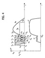
- FIG. 2 to 4 illustrates: a corresponding top graph, which represents, as a function of time T, the waveforms C of the electrical commands supplied, according to the present invention, to the device 8 (dashed line) and the motion profile P of motion or plot of the axial position assumed by the pin 7 (solid line), in response to said commands, with respect to the ordinate "zero" in which the nozzle 5 is closed; and a corresponding bottom graph, which represents, as a function of time T, the curve F of the instantaneous flow rate of fuel (solid line) injected through the nozzle 5 and caused by the displacement of the pin 7 shown in the corresponding top graph.
- the device 8 receives signals of electric current, the curve C of which presents, after the trailing edge R, a stretch M of holding around a maximum value, a stretch D of decrease down to an intermediate value, a stretch N of holding around said intermediate value, and a stretch E of final decrease.
- a first electrical command and at least a second electrical command supplied to the device 8 are a first electrical command and at least a second electrical command, which are sufficiently close to one another as to displace the pin 7 with a profile P of motion without any discontinuity in time and such as to cause the pin 7 to perform a first and, respectively, a second opening displacement, or lifts, which are defined in the profile P by respective stretches A, increase up to relative-maximum values H, and are followed by respective closing displacements defined by decreasing stretches B of the profile P.
- the curve C 1 causes displacement of the pin 7 with a profile P comprising the increasing stretch A 1 , up to the value H 1 , and the decreasing stretch B 1 .
- a second command is supplied at an instant T 2 such as to start the second lift, i.e., the stretch A 2 , in a point Q 1 of the stretch B 1 , before the pin 7 has reached the position of end-of-closing stroke of the nozzle 5.
- the instant T 2 is smaller than the theoretical instant in which the first command represented by the curve C 1 would reach a zero value.
- the curve C 2 has a stretch N 2 of duration longer than the stretch N 1 , so that the lift of the pin 7 reaches a value H 2 greater than H 1 , causing a degree or section of opening of the nozzle 5 greater than that reached at the end of the stretch A 1 .
- the curve F of the instantaneous flow rate obtained approximates in a satisfactory manner the desired curve of instantaneous flow rate illustrated in Figure 1, in so far as it presents two consecutive portions S and U, which have respective maximum levels that are different from one another and respective mean levels that are different from one another and approximate the levels L1 and L2, respectively. It is evident that the instant in which the portion S ends and the portion U starts corresponds to the time abscissa of the point Q 1 (TQ 1 ).
- the device 8 receives in succession two electrical commands, which are designated by the subscripts or reference numbers 3 and 4, respectively, and which cause the pin 7 to be displaced with a profile P' of motion (solid line) which is again without any discontinuity in time, i.e., without dwell times, between the stretch B 3 and the stretch A 4 , but in a limit condition, i.e., supplying the second electrical command at an instant T 4 such as to start the second lift (stretch A 4 ) at a final point Q 3 of the stretch B 3 , i.e., when the pin 7 has just reached the position of end-of-closing stroke.
- a limit condition i.e., supplying the second electrical command at an instant T 4 such as to start the second lift (stretch A 4 ) at a final point Q 3 of the stretch B 3 , i.e., when the pin 7 has just reached the position of end-of-closing stroke.
- the instant T 4 is greater than the instant at which the stretch E 3 of the curve C 3 goes to zero.
- the curve F' of instantaneous flow rate obtained comprises two consecutive portions S' and U', which have respective maximum levels that are different from one another and respective mean levels that are different from one another and approximate still in a satisfactory manner the levels L1 and L2, respectively, of the desired instantaneous-flow curve of Figure 1. It is evident that the instant at which the portion S' ends and the portion U' starts corresponds to the time abscissa of the point Q 3 (QT 3 ).
- the device 8 receives four electrical commands in succession, which are designated, respectively, by the reference numbers or subscripts 5-8, and are supplied in respective instants T 5 -T 8 sufficiently close to one another as to displace the pin 7 with a profile P" of motion that is once again without any discontinuity in time.
- the instants T 6 -T 8 are greater than the instants at which the stretches E 5 -E 7 , respectively, go to zero.
- the stretches A 6 -A 8 start in respective points Q 5 -Q 7 of the stretches B 5 -B 7 in which the pin 7 has not yet reached the position of end-of-closing stroke of the nozzle 5.
- the values H 5 -H 7 (relative-maximum values) reached by the pin 7 at the end of the first three lifts are substantially equal to one another, so that the relative maximum opening sections of the nozzle 5 are substantially the same as one another.
- the value H 8 reached at the end of the fourth and last lift (stretch A 8 ) is greater and causes a greater degree or section of opening, in so far as the stretch N 8 has a duration longer than the stretches N 5 -N 7 .
- the curve F" comprises, up to an instant TQ 7 coinciding with the abscissa of the point Q 7 , a portion S" which has three “peaks” and approximates the level L1 of the curve of Figure 1 and, after the instant TQ 7 , a portion U", which has mean and maximum levels greater than those of the portion S" and which approximates the level L2 of the curve of Figure 1.
- At least one of the following quantities is determined as a function of operating parameters of the engine:
- At least one among the following quantities is varied as a function of operating parameters of the engine, in particular as a function of the load:
- control of injection according to the method described above does not require any calibration of mechanical components and/or injectors made in a dedicated manner.
- the curve of the flow injected can be easily varied between one injection and the next so as to approximate as well as possible the desired flow-rate curve and optimize the efficiency of the engine according to the specific point of operation of the engine itself.
- control method could be implemented with injectors that are different from the electroinjector 1 illustrated by way of example, but in which the displacement of the open/close pin of the nozzle is always performed as a function of the pressure of supply of the fuel and is repeatable in response to given electrical commands.
- the device 8 could comprise a piezoelectric actuator, instead of an electromagnet.
- the pin 7 could be displaced during lifting in one and the same injection for a number of times and/or by amounts different from those indicated by way of example.
Landscapes
- Engineering & Computer Science (AREA)
- Chemical & Material Sciences (AREA)
- Combustion & Propulsion (AREA)
- Mechanical Engineering (AREA)
- General Engineering & Computer Science (AREA)
- Fuel-Injection Apparatus (AREA)
- Electrical Control Of Air Or Fuel Supplied To Internal-Combustion Engine (AREA)
Abstract
Description
- The present invention relates to a method for controlling fuel injection in an internal-combustion engine.
- In the engine sector, there is felt the need to make injections of fuel in which the instantaneous flow rate of injected fuel as a function of time comprises at least two stretches with levels that are substantially constant and different from one another, i.e., it can be represented schematically by a curve of the "stepwise" type. In particular, there is felt the need to inject an instantaneous flow of fuel having a plot in time T similar to the one represented by the curve of Figure 1, in which there is present a first level L1 and a subsequent second level L2 higher than the first.
- In an endeavour to obtain said flow-rate curve, it is known to provide injectors of a dedicated type, in which opening of the injection nozzle is caused by the lifting of two movable open/close pins co-operating with respective springs, or else by the lifting of a single movable open/close pin co-operating with two coaxial springs. In particular, the two springs are differently preloaded with respect to one another, and/or present characteristics of force/displacement that are different from one another, for opening the nozzle with lifts such as to approximate the required flow-rate curve.
- The known solutions just described are far from altogether satisfactory in so far as it is somewhat complex to calibrate the springs in an optimal way to obtain a first level or step of flow rate smaller than the maximum flow rate from the nozzle and, hence, to approximate a flow-rate curve like the one of Figure 1.
- Furthermore, given the same pressure of supply of the fuel, once the law of lifting of the pins and, hence, the law of opening of the nozzle, has been established, the profile of flow rate of injected fuel is not modifiable as the operating conditions of the engine vary between the various injections performed by the injector.
- In addition, it is somewhat difficult to obtain injectors with a profile of flow rate of injected fuel constant for the entire production.
- The purpose of the present invention is to provide a method for controlling fuel injection in an internal-combustion engine which will enable the drawbacks set forth above to be overcome in a simple and economically advantageous way.
- According to the present invention, a method is provided for controlling fuel injection in an internal-combustion engine provided with an electroinjector comprising:
- an electroactuator; and
- an atomizer, comprising an injection nozzle and a pin, which is movable along an opening stroke and a closing stroke for opening/closing said nozzle under the control of said electroactuator; the electroinjector performing dosage of the fuel by modulating in time opening of the pin of the atomizer according to the pressure of supply of the electroinjector itself;
- For a better understanding of the present invention, there now follows a description of a preferred embodiment, which is provided purely by way of non-limiting example, with reference to the attached drawings, in which:
- Figure 1 shows a desired curve of instantaneous flow-rate of fuel as a function of time during one injection in an internal-combustion engine;
- Figures 2 to 4 show graphs for operation of an electroinjector according to preferred embodiments of the method for controlling fuel injection in an internal-combustion engine of the present invention; and
- Figure 5 shows, in cross section and with parts removed for reasons of clarity, an electroinjector for implementing the method of the present invention.
- In Figure 5, the reference number 1 designates, as a whole, an electroinjector (partially illustrated) of an internal-combustion engine, in particular a diesel-cycle engine (not illustrated) .
- The electroinjector 1 comprises an external structure or
shell 2, which extends along alongitudinal axis 3, has a side inlet 4 designed to be connected to a system (not illustrated) for supply of fuel, and ends with a atomizer. - The atomizer comprises a
nozzle 5 communicating with the inlet 4 and designed to inject the fuel into a combustion chamber, and an open/close pin 7 or needle, which is movable along an opening stroke and a closing stroke for opening/closing thenozzle 5 under the control of an electrically controlledactuator device 8, or electroactuator. The electroinjector 1 carries out dosage of the fuel by modulating in time opening of the pin 7 of the atomizer according to the pressure of supply of the electroinjector 1 itself, i.e., of the pressure at the inlet 4, as will emerge more clearly from the ensuing description. - The
device 8 is preferably of the type comprising: anelectromagnet 10; ananchor 11, which is axially slidable in theshell 2 under the action of theelectromagnet 10; and apre-loaded spring 12, which is surrounded by theelectromagnet 10 and exerts an action of thrust on theanchor 11 in a direction opposite to the attraction exerted by theelectromagnet 10. - The
shell 2 has anaxial seat 13, which is illustrated with parts removed for reasons of clarity in Figure 5 and is obtained as a prolongation of the seat in which the pin 7 slides. An intermediate stretch of theseat 13 houses abody 13a having the shape of a glass turned upside down (partially illustrated), which is coupled to theshell 2 in a fixed position and in a fluid-tight way and has anaxial seat 13b. Theseat 13b houses arod 14, which is axially slidable in theseats control chamber 15. - The
chamber 15 constitutes the end portion of theseat 13b, defines part of a control servo-valve 16 and communicates permanently with the inlet 4 through apassage 18 made in theshell 2 and in thebody 13a for receiving fuel under pressure, so that modulation of opening and closing of the pin 7 exerted by therod 14 is performed according to the pressure of supply of the fuel into the electroinjector 1. - The
chamber 15 is axially delimited, on one side, by therod 14 and, on the other, by an end portion of thebody 13a, to which there is then set axially alongside adisk 20, fixed with respect to theshell 2 by means of an appropriate clamping system. - The servo-
valve 16 further comprises apassage 22, which defines the outlet of thechamber 15, is substantially symmetrical with respect to theaxis 3 and is made in thebody 13a, in thedisk 20, and in adistribution body 25 set in an intermediate axial position between thedisk 20 and thedevice 8. Thebody 25 is fixed with respect to theshell 2, is axially coupled in a fluid-tight way to thedisk 20 so that it bears thereupon, and ends with a stem orpin 29 delimited by acylindrical side surface 30, dug into which is anannular chamber 34 in which there gives out thepassage 22. - The radial outlet of the
passage 22, defined by thechamber 34, is designed to be opened/closed by an open/close element defined by asleeve 35, which is fitted on thestem 29 and is axially slidable under the action of thedevice 8 for varying the pressure present in thechamber 15 and, hence, for opening/closing thenozzle 5. - It is evident that, when the
sleeve 35 closes thechamber 34, it is subjected to a resultant of pressure that is zero along theaxis 3 by the fuel, with consequent advantages from the standpoint of stability of dynamic behaviour of the movable parts of the injector 1. - In particular, displacement of the pin 7 along the opening stroke, i.e., during lifting, and along the closing stroke is practically constant between one injection and the next in response to a given electrical command sent to the
device 8. In other words, it is possible to correlate in a biunique and repeatable manner the position of the pin 7 with the electrical commands supplied to thedevice 8. The position of the pin 7 along the opening and closing strokes in response to an electrical command can be known via theoretical calculation, as a function of constructional parameters of the injector 1 (for example sections of passage of the servo-valve 16) and as a function of known operating parameters (for example, pressure of supply of the fuel into the inlet 4), or else experimentally by means of a "sample" injector on which appropriate sensors are mounted. At the same time, the opening section of thenozzle 5 and, hence, the instantaneous flow-rate pattern of the fuel can be determined in a unique way as a function of the axial displacement of the pin 7, in particular on the basis of the dimensions of the passages of thenozzle 5 itself and on the basis of the pressure of supply of the fuel. - Each of Figures 2 to 4 illustrates: a corresponding top graph, which represents, as a function of time T, the waveforms C of the electrical commands supplied, according to the present invention, to the device 8 (dashed line) and the motion profile P of motion or plot of the axial position assumed by the pin 7 (solid line), in response to said commands, with respect to the ordinate "zero" in which the
nozzle 5 is closed; and a corresponding bottom graph, which represents, as a function of time T, the curve F of the instantaneous flow rate of fuel (solid line) injected through thenozzle 5 and caused by the displacement of the pin 7 shown in the corresponding top graph. - In Figures 2-4, the commands are associated to respective reference numbers, which appear as subscripts near to the reference letters that designate the various parts of the corresponding graphs.
- For reasons of clarity, by the term "command" is meant, in the present description and in the annexed claims, an electrical signal having a curve C that initially has a trailing edge or ramp R with a relatively fast initial increase. In the particular examples illustrated, the
device 8 receives signals of electric current, the curve C of which presents, after the trailing edge R, a stretch M of holding around a maximum value, a stretch D of decrease down to an intermediate value, a stretch N of holding around said intermediate value, and a stretch E of final decrease. - According to the method of the present invention, to obtain a fuel injection, supplied to the
device 8 are a first electrical command and at least a second electrical command, which are sufficiently close to one another as to displace the pin 7 with a profile P of motion without any discontinuity in time and such as to cause the pin 7 to perform a first and, respectively, a second opening displacement, or lifts, which are defined in the profile P by respective stretches A, increase up to relative-maximum values H, and are followed by respective closing displacements defined by decreasing stretches B of the profile P. - With reference to the example of Figure 2, at the instant T1 there is supplied a first command, the curve C1 of which increases with the ramp R1, remains then substantially constant (stretch M1), then decreases along the stretch D1, has a substantially constant stretch (stretch N1), and finally decreases (stretch E1).
- The curve C1 causes displacement of the pin 7 with a profile P comprising the increasing stretch A1, up to the value H1, and the decreasing stretch B1. A second command is supplied at an instant T2 such as to start the second lift, i.e., the stretch A2, in a point Q1 of the stretch B1, before the pin 7 has reached the position of end-of-closing stroke of the
nozzle 5. In particular, the instant T2 is smaller than the theoretical instant in which the first command represented by the curve C1 would reach a zero value. The curve C2 has a stretch N2 of duration longer than the stretch N1, so that the lift of the pin 7 reaches a value H2 greater than H1, causing a degree or section of opening of thenozzle 5 greater than that reached at the end of the stretch A1. - There then follows a closing displacement defined by the stretch B2 up to complete closing of the
nozzle 5, after which the pin 7 remains stationary until the subsequent injection. - The curve F of the instantaneous flow rate obtained approximates in a satisfactory manner the desired curve of instantaneous flow rate illustrated in Figure 1, in so far as it presents two consecutive portions S and U, which have respective maximum levels that are different from one another and respective mean levels that are different from one another and approximate the levels L1 and L2, respectively. It is evident that the instant in which the portion S ends and the portion U starts corresponds to the time abscissa of the point Q1 (TQ1).
- According to the example of Figure 3, the
device 8 receives in succession two electrical commands, which are designated by the subscripts orreference numbers 3 and 4, respectively, and which cause the pin 7 to be displaced with a profile P' of motion (solid line) which is again without any discontinuity in time, i.e., without dwell times, between the stretch B3 and the stretch A4, but in a limit condition, i.e., supplying the second electrical command at an instant T4 such as to start the second lift (stretch A4) at a final point Q3 of the stretch B3, i.e., when the pin 7 has just reached the position of end-of-closing stroke. In particular, the instant T4 is greater than the instant at which the stretch E3 of the curve C3 goes to zero. Albeit in a limit condition, the curve F' of instantaneous flow rate obtained comprises two consecutive portions S' and U', which have respective maximum levels that are different from one another and respective mean levels that are different from one another and approximate still in a satisfactory manner the levels L1 and L2, respectively, of the desired instantaneous-flow curve of Figure 1. It is evident that the instant at which the portion S' ends and the portion U' starts corresponds to the time abscissa of the point Q3 (QT3). - According to the example of Figure 4, the
device 8 receives four electrical commands in succession, which are designated, respectively, by the reference numbers or subscripts 5-8, and are supplied in respective instants T5-T8 sufficiently close to one another as to displace the pin 7 with a profile P" of motion that is once again without any discontinuity in time. In particular, the instants T6-T8 are greater than the instants at which the stretches E5-E7, respectively, go to zero. In a way similar to the example of Figure 2, the stretches A6-A8 start in respective points Q5-Q7 of the stretches B5-B7 in which the pin 7 has not yet reached the position of end-of-closing stroke of thenozzle 5. - The values H5-H7 (relative-maximum values) reached by the pin 7 at the end of the first three lifts are substantially equal to one another, so that the relative maximum opening sections of the
nozzle 5 are substantially the same as one another. The value H8 reached at the end of the fourth and last lift (stretch A8) is greater and causes a greater degree or section of opening, in so far as the stretch N8 has a duration longer than the stretches N5-N7. - There is consequently obtained a curve F" of flow rate which approximates the desired flow-rate curve of Figure 1 in a better way, in so far as it approaches more closely a "stepwise" curve. In particular, the curve F" comprises, up to an instant TQ7 coinciding with the abscissa of the point Q7, a portion S" which has three "peaks" and approximates the level L1 of the curve of Figure 1 and, after the instant TQ7, a portion U", which has mean and maximum levels greater than those of the portion S" and which approximates the level L2 of the curve of Figure 1.
- According to variants (not illustrated), it is possible to approximate curves of instantaneous flow rate of the "stepwise" type, in which there are present more than two levels, by causing the pin 7 to be displaced with more than two consecutive lifts up to values H that are different from one another, and/or to approximate curves of instantaneous flow rate, in which a level is followed by a lower level (instead of the levels L1 and L2 illustrated by way of example), by supplying electrical commands having appropriate durations and magnitudes.
- Furthermore, according to the method of the present invention, for at least one injection, at least one of the following quantities is determined as a function of operating parameters of the engine:
- duration of at least one of the electrical commands to be supplied to the
device 8; - number of the electrical commands to be supplied to the
device 8; and - distance in time between the start of the electrical commands to be supplied to the
device 8. - In particular, between one injection and the next, at least one among the following quantities is varied as a function of operating parameters of the engine, in particular as a function of the load:
- duration of at least one of the electrical commands;
- number of the electrical commands; and
- distance in time between the electrical commands.
- In this way, it is possible to modulate the curve of the instantaneous flow rate between the various injections by varying the amplitude and/or duration and/or the number of the substantially constant levels of flow rate that it is desired to approximate.
- From the foregoing description it is evident how it is possible to inject an instantaneous flow rate that approximates in an optimal manner flow-rate curves of the "stepwise" type and how this is obtained in a relatively simple way.
- In fact, the control of injection according to the method described above does not require any calibration of mechanical components and/or injectors made in a dedicated manner.
- Furthermore, the curve of the flow injected can be easily varied between one injection and the next so as to approximate as well as possible the desired flow-rate curve and optimize the efficiency of the engine according to the specific point of operation of the engine itself.
- From the foregoing description, it is evident how the control method described can undergo modifications and variations that do not depart from the sphere of protection of the present invention.
- In particular, the control method could be implemented with injectors that are different from the electroinjector 1 illustrated by way of example, but in which the displacement of the open/close pin of the nozzle is always performed as a function of the pressure of supply of the fuel and is repeatable in response to given electrical commands.
- Furthermore, the
device 8 could comprise a piezoelectric actuator, instead of an electromagnet. - Furthermore, the pin 7 could be displaced during lifting in one and the same injection for a number of times and/or by amounts different from those indicated by way of example.
Claims (12)
- A method for controlling fuel injection in an internal-combustion engine provided with an electroinjector (1) comprising:- an electroactuator (8); and- an atomizer, comprising an injection nozzle (5) and a pin (7), which is movable along an opening stroke and a closing stroke for opening/closing said nozzle (5) under the control of said electroactuator (8); the electroinjector (1) performing dosage of the fuel by modulating in time opening of the pin (7) of the atomizer according to the pressure of supply of the electroinjector itself;the method being characterized by supplying to said electroactuator (8) a first electrical command (C1) and at least a second electrical command (C2) that are sufficiently close to one another as to displace said pin (7) with a profile of motion (P) without any discontinuity in time, and such as to cause said pin (7) to perform a first opening displacement (A1) and a second opening displacement (A2), respectively.
- The method according to Claim 1, characterized in that said second electrical command (C2) is supplied at an instant such as to start said second opening displacement (A2) when said pin (7) is displacing along said closing stroke.
- The method according to Claim 1, characterized in that said second electrical command (C4) is supplied at an instant (T4) such as to start said second opening displacement (A4) when said pin (7) has just reached the end (Q3) of said closing stroke.
- The method according to any one of the preceding claims, characterized in that said first electrical command (C1) and second electrical command (C2) are supplied in such a way to reach, at the end of said first opening displacement (A1) and second opening displacement (A2), a first degree of opening (H1) of said nozzle (5) and, respectively, a second degree of opening (H2) of said nozzle (5), which are different from one another.
- The method according to Claim 4, characterized in that said first electrical command (C1) is supplied prior to said second electrical command (C2), and in such a way that said second degree of opening (H2) is greater than said first degree of opening (H1) .
- The method according to any one of the preceding claims, characterized in that said second electrical command (C2) is supplied at an instant (T2) in which said first electrical command (C1) is different from zero.
- The method according to any of the preceding claims, characterized by supplying to said electroactuator (8) at least a third electrical command (C5-C8) sufficiently close to said first and second electrical commands (C5-C8) as to displace said pin (7) with a profile of motion (P"), without any discontinuity in time and such as to cause said pin (7) to perform a third opening displacement (A5-A8) in succession to said first and second opening displacements (A5-A8).
- The method according to Claim 7, characterized in that said first, second and third electrical commands (C5-C8) are supplied in such a way as to cause, at the end of said first, second and third opening displacements (A5-A8), a first degree, a second degree and, respectively, a third degree of opening (H5-H8) to be reached, and in such a way that said first and second degrees of opening (H5-H7) are smaller than said third degree of opening (H8).
- The method according to Claim 8, characterized in that said first and second electrical commands (C5-C7) are supplied consecutively with respect to one another and prior to said third electrical command (C8).
- The method according to Claim 8 or Claim 9, characterized in that said first and second electrical commands (C5-C7) are supplied in such a way that said first and second degrees of opening (H5-H7) are equal to one another.
- The method according to any of the preceding claims, characterized by determining, for at least one injection, at least one among the following quantities as a function of operating parameters of said engine:- duration of at least one among said electrical commands;- number of said electrical commands; and- distance in time between said electrical commands.
- The method according to Claim 11, characterized by varying, between one injection and the next, at least one among the following quantities as a function of operating parameters of said engine:- duration of at least one among said electrical commands;- number of said electrical commands;- distance in time between said electrical commands.
Priority Applications (5)
| Application Number | Priority Date | Filing Date | Title |
|---|---|---|---|
| EP04425841A EP1657422A1 (en) | 2004-11-12 | 2004-11-12 | A method for controlling fuel injection in an internal combustion engine |
| US11/109,789 US7131428B2 (en) | 2004-11-12 | 2005-04-20 | Method for controlling fuel injection in an internal-combustion engine |
| JP2005129347A JP4282633B2 (en) | 2004-11-12 | 2005-04-27 | Fuel injection control method for internal combustion engine |
| US11/452,391 US7360528B2 (en) | 2004-11-12 | 2006-06-14 | Electroinjector for controlling fuel injection in an internal-combustion engine |
| US12/763,479 USRE44544E1 (en) | 2004-11-12 | 2010-04-20 | Electroinjector for controlling fuel injection in an internal-combustion engine |
Applications Claiming Priority (1)
| Application Number | Priority Date | Filing Date | Title |
|---|---|---|---|
| EP04425841A EP1657422A1 (en) | 2004-11-12 | 2004-11-12 | A method for controlling fuel injection in an internal combustion engine |
Publications (1)
| Publication Number | Publication Date |
|---|---|
| EP1657422A1 true EP1657422A1 (en) | 2006-05-17 |
Family
ID=34932880
Family Applications (1)
| Application Number | Title | Priority Date | Filing Date |
|---|---|---|---|
| EP04425841A Ceased EP1657422A1 (en) | 2004-11-12 | 2004-11-12 | A method for controlling fuel injection in an internal combustion engine |
Country Status (3)
| Country | Link |
|---|---|
| US (3) | US7131428B2 (en) |
| EP (1) | EP1657422A1 (en) |
| JP (1) | JP4282633B2 (en) |
Cited By (5)
| Publication number | Priority date | Publication date | Assignee | Title |
|---|---|---|---|---|
| US7360528B2 (en) * | 2004-11-12 | 2008-04-22 | C.R.F. Società Consortile Per Azioni | Electroinjector for controlling fuel injection in an internal-combustion engine |
| WO2010076645A1 (en) | 2008-12-29 | 2010-07-08 | C.R.F. Società Consortile Per Azioni | High operation repeatability and stability fuel injection system for an internal combustion engine |
| EP2383454A1 (en) | 2010-04-27 | 2011-11-02 | C.R.F. Società Consortile per Azioni | Fuel injection rate shaping in an internal combustion engine |
| EP2405121A1 (en) | 2010-07-07 | 2012-01-11 | C.R.F. Società Consortile per Azioni | Fuel-injection system for an internal-combustion engine |
| DE102011082999A1 (en) | 2011-09-20 | 2013-03-21 | Robert Bosch Gmbh | Method for assessing operational capability of fuel injection valve of internal combustion engine, involves activating injection process of injection valve when main injection estimation or calibration function are within preset limit |
Families Citing this family (10)
| Publication number | Priority date | Publication date | Assignee | Title |
|---|---|---|---|---|
| KR20080055908A (en) | 2005-09-12 | 2008-06-19 | 다우 글로벌 테크놀로지스 인크. | Automotive parts made from ethylene / alpha-olefin compositions |
| JP5588872B2 (en) * | 2007-10-22 | 2014-09-10 | スティロン ヨーロッパ ゲゼルシャフト ミット ベシュレンクテル ハフツング | Polymer compositions and methods for molding articles |
| EP2138708B1 (en) * | 2008-06-27 | 2010-11-03 | C.R.F. Società Consortile per Azioni | Fuel injector equipped with a metering servovalve for an internal combustion engine |
| US9464613B2 (en) | 2008-06-27 | 2016-10-11 | C.R.F. Societa Consortile Per Azioni | Fuel injector equipped with a metering servovalve for an internal combustion engine |
| DE102009003214A1 (en) * | 2009-05-19 | 2010-11-25 | Robert Bosch Gmbh | Method for operating a fuel injection valve of an internal combustion engine and control unit for an internal combustion engine |
| US20120080536A1 (en) * | 2010-10-05 | 2012-04-05 | GM Global Technology Operations LLC | Method for controlling a fuel injector |
| JP5956206B2 (en) * | 2012-03-16 | 2016-07-27 | 花王株式会社 | Nonwoven fabric and method for producing the same |
| DE102012213883B4 (en) * | 2012-08-06 | 2015-03-26 | Continental Automotive Gmbh | Equalization of the current flow through a fuel injector for different partial injection processes of a multiple injection |
| JP6156397B2 (en) | 2015-01-14 | 2017-07-05 | トヨタ自動車株式会社 | Internal combustion engine |
| WO2017123582A1 (en) | 2016-01-11 | 2017-07-20 | Avisa Pharma Inc. | Methods for detecting bacterial lung infections |
Citations (5)
| Publication number | Priority date | Publication date | Assignee | Title |
|---|---|---|---|---|
| EP0570986A2 (en) * | 1992-05-21 | 1993-11-24 | Nippondenso Co., Ltd. | Fuel injection control apparatus for internal combustion engine |
| FR2761113A1 (en) * | 1997-03-18 | 1998-09-25 | Denso Corp | METHOD AND SYSTEM FOR REGULATING FUEL INJECTION |
| JPH11200932A (en) * | 1998-01-16 | 1999-07-27 | Mitsubishi Motors Corp | Fuel injection control device |
| US6059204A (en) * | 1997-12-20 | 2000-05-09 | Daimlerchrysler Ag | Accumulator injection system |
| US6415762B1 (en) * | 2000-07-13 | 2002-07-09 | Caterpillar Inc. | Accurate deliver of total fuel when two injection events are closely coupled |
Family Cites Families (22)
| Publication number | Priority date | Publication date | Assignee | Title |
|---|---|---|---|---|
| US4732129A (en) * | 1985-04-15 | 1988-03-22 | Nippon Soken, Inc. | Control apparatus for electroexpansive actuator enabling variation of stroke |
| JPH086627B2 (en) * | 1985-06-04 | 1996-01-29 | 株式会社日本自動車部品総合研究所 | Fuel injection control method and control device for diesel engine |
| US4688536A (en) * | 1985-06-28 | 1987-08-25 | Toyota Jidosha Kabushiki Kaisha | Drive circuit for an electrostrictive actuator in a fuel injection valve |
| DE3712310A1 (en) * | 1986-04-11 | 1987-10-29 | Nippon Denso Co | FUEL INJECTION VALVE USED IN A FUEL INJECTION DEVICE FOR AN INTERNAL COMBUSTION ENGINE |
| JPH07109181B2 (en) * | 1986-12-05 | 1995-11-22 | 日本電装株式会社 | Fuel injection device for internal combustion engine |
| JPS63277841A (en) | 1987-05-01 | 1988-11-15 | Diesel Kiki Co Ltd | Fuel injection control device for internal combustion engine |
| JP2568603B2 (en) * | 1988-01-11 | 1997-01-08 | 日産自動車株式会社 | Fuel injection device |
| DE3816165A1 (en) | 1988-05-11 | 1989-11-23 | Bosch Gmbh Robert | CONTROL SYSTEM FOR A DIESEL INTERNAL COMBUSTION ENGINE |
| JPH051609A (en) | 1991-06-25 | 1993-01-08 | Toyota Motor Corp | Fuel injection control device of diesel engine |
| JP3052572B2 (en) | 1992-05-21 | 2000-06-12 | 株式会社デンソー | Fuel injection control device for internal combustion engine |
| DE4310984A1 (en) * | 1993-04-03 | 1994-10-06 | Rexroth Mannesmann Gmbh | Electromagnetically operable hydraulic control valve |
| GB9616521D0 (en) * | 1996-08-06 | 1996-09-25 | Lucas Ind Plc | Injector |
| IT1296143B1 (en) | 1997-11-18 | 1999-06-09 | Elasis Sistema Ricerca Fiat | CONTROL DEVICE FOR A FUEL INJECTOR FOR INTERNAL COMBUSTION ENGINES. |
| US6761325B2 (en) * | 1998-09-16 | 2004-07-13 | Westport Research Inc. | Dual fuel injection valve and method of operating a dual fuel injection valve |
| IT1308412B1 (en) * | 1999-03-05 | 2001-12-17 | Fiat Ricerche | METHOD OF COMBUSTION CONTROL OF A DIRECT INJECTION DIESEL ENGINE THROUGH THE IMPLEMENTATION OF MULTIPLE INJECTIONS USING A SYSTEM |
| DE19941463A1 (en) * | 1999-09-01 | 2001-03-15 | Bosch Gmbh Robert | Magnet injector for fuel storage injection systems |
| US6467452B1 (en) * | 2000-07-13 | 2002-10-22 | Caterpillar Inc | Method and apparatus for delivering multiple fuel injections to the cylinder of an internal combustion engine |
| US6378487B1 (en) | 2000-09-01 | 2002-04-30 | International Truck And Engine Corporation | Method and apparatus for pre-pilot fuel injection in diesel internal combustion engines |
| DE10213025B4 (en) * | 2002-03-22 | 2014-02-27 | Daimler Ag | Auto-ignition internal combustion engine |
| JP4007103B2 (en) * | 2002-07-11 | 2007-11-14 | 株式会社豊田中央研究所 | Fuel injection device |
| JP4075588B2 (en) * | 2002-11-26 | 2008-04-16 | いすゞ自動車株式会社 | diesel engine |
| EP1657422A1 (en) * | 2004-11-12 | 2006-05-17 | C.R.F. Societa' Consortile per Azioni | A method for controlling fuel injection in an internal combustion engine |
-
2004
- 2004-11-12 EP EP04425841A patent/EP1657422A1/en not_active Ceased
-
2005
- 2005-04-20 US US11/109,789 patent/US7131428B2/en not_active Expired - Lifetime
- 2005-04-27 JP JP2005129347A patent/JP4282633B2/en not_active Expired - Lifetime
-
2006
- 2006-06-14 US US11/452,391 patent/US7360528B2/en not_active Ceased
-
2010
- 2010-04-20 US US12/763,479 patent/USRE44544E1/en not_active Expired - Lifetime
Patent Citations (5)
| Publication number | Priority date | Publication date | Assignee | Title |
|---|---|---|---|---|
| EP0570986A2 (en) * | 1992-05-21 | 1993-11-24 | Nippondenso Co., Ltd. | Fuel injection control apparatus for internal combustion engine |
| FR2761113A1 (en) * | 1997-03-18 | 1998-09-25 | Denso Corp | METHOD AND SYSTEM FOR REGULATING FUEL INJECTION |
| US6059204A (en) * | 1997-12-20 | 2000-05-09 | Daimlerchrysler Ag | Accumulator injection system |
| JPH11200932A (en) * | 1998-01-16 | 1999-07-27 | Mitsubishi Motors Corp | Fuel injection control device |
| US6415762B1 (en) * | 2000-07-13 | 2002-07-09 | Caterpillar Inc. | Accurate deliver of total fuel when two injection events are closely coupled |
Non-Patent Citations (1)
| Title |
|---|
| PATENT ABSTRACTS OF JAPAN vol. 1999, no. 12 29 October 1999 (1999-10-29) * |
Cited By (16)
| Publication number | Priority date | Publication date | Assignee | Title |
|---|---|---|---|---|
| US7360528B2 (en) * | 2004-11-12 | 2008-04-22 | C.R.F. Società Consortile Per Azioni | Electroinjector for controlling fuel injection in an internal-combustion engine |
| USRE44544E1 (en) | 2004-11-12 | 2013-10-22 | C. R. F. Societa Consortile Per Azioni | Electroinjector for controlling fuel injection in an internal-combustion engine |
| CN101769217B (en) * | 2008-12-29 | 2013-04-10 | C.R.F.阿西安尼顾问公司 | Fuel injection system with high repeatability and stability of operation for an internal-combustion engine |
| WO2010076645A1 (en) | 2008-12-29 | 2010-07-08 | C.R.F. Società Consortile Per Azioni | High operation repeatability and stability fuel injection system for an internal combustion engine |
| EP2211046A1 (en) * | 2008-12-29 | 2010-07-28 | C.R.F. Società Consortile per Azioni | Fuel injection system with high repeatability and stability of operation for an internal-combustion engine |
| US9140223B2 (en) | 2008-12-29 | 2015-09-22 | C.R.F. SOCIETá CONSORTILE PER AZIONI | Fuel injection system with high repeatability and stability of operation for an internal-combustion engine |
| CN102333947B (en) * | 2008-12-29 | 2015-05-20 | C.R.F.阿西安尼顾问公司 | High operation repeatability and stability fuel injection system for an internal combustion engine |
| US8807116B2 (en) | 2008-12-29 | 2014-08-19 | C.R.F. Societa Consortile Per Azioni | High operation repeatability and stability fuel injection system for an internal combustion engine |
| CN102333947A (en) * | 2008-12-29 | 2012-01-25 | C.R.F.阿西安尼顾问公司 | High operation repeatability and stability fuel injection system for an internal combustion engine |
| WO2011135442A1 (en) | 2010-04-27 | 2011-11-03 | C.R.F. Società Consortile Per Azioni | Fuel injection rate shaping in an internal combustion engine |
| EP2383454A1 (en) | 2010-04-27 | 2011-11-02 | C.R.F. Società Consortile per Azioni | Fuel injection rate shaping in an internal combustion engine |
| WO2012004368A1 (en) | 2010-07-07 | 2012-01-12 | C.R.F. Società Consortile Per Azioni | Fuel-injection system for an internal-combustion engine |
| EP2405121A1 (en) | 2010-07-07 | 2012-01-11 | C.R.F. Società Consortile per Azioni | Fuel-injection system for an internal-combustion engine |
| US9068544B2 (en) | 2010-07-07 | 2015-06-30 | C.R.F. Società Consortile Per Azioni | Fuel-injection system for an internal-combustion engine |
| CN103119274B (en) * | 2010-07-07 | 2015-11-25 | C.R.F.阿西安尼顾问公司 | For the fuel injection system of internal-combustion engine |
| DE102011082999A1 (en) | 2011-09-20 | 2013-03-21 | Robert Bosch Gmbh | Method for assessing operational capability of fuel injection valve of internal combustion engine, involves activating injection process of injection valve when main injection estimation or calibration function are within preset limit |
Also Published As
| Publication number | Publication date |
|---|---|
| US20060231077A1 (en) | 2006-10-19 |
| USRE44544E1 (en) | 2013-10-22 |
| JP2006138310A (en) | 2006-06-01 |
| US7360528B2 (en) | 2008-04-22 |
| US20060102154A1 (en) | 2006-05-18 |
| JP4282633B2 (en) | 2009-06-24 |
| US7131428B2 (en) | 2006-11-07 |
Similar Documents
| Publication | Publication Date | Title |
|---|---|---|
| USRE44544E1 (en) | Electroinjector for controlling fuel injection in an internal-combustion engine | |
| KR20090089281A (en) | Fuel injection system for internal combustion engine and method for controlling fuel injection | |
| EP2373877B1 (en) | High operation repeatability and stability fuel injection system for an internal combustion engine | |
| US6978770B2 (en) | Piezoelectric fuel injection system with rate shape control and method of controlling same | |
| KR20130105599A (en) | Fuel-inject ion system for an internal-combustion engine | |
| JP2005526211A (en) | Fuel injection valve for internal combustion engine | |
| DK177420B1 (en) | Fuel valve for large turbocharged two-stroke diesel engines | |
| RU2517518C2 (en) | Fuel injector with electromagnet armature composed of two parts | |
| CN102066730B (en) | Electronic pressure relief in a mechanically actuated fuel injector | |
| US20070023542A1 (en) | Fuel injector with variable actuator stroke transmission | |
| US8955775B2 (en) | Valve system | |
| US7398933B2 (en) | Injection valve | |
| CN101532455B (en) | Injection valves for direct injection | |
| GB2332477A (en) | Common rail i.c. engine fuel injector system with solenoid valve controlled injection valves | |
| US6439483B2 (en) | Variable orifice electronically controlled common rail injector (VOECRRI) | |
| US7150410B1 (en) | Method for providing a controlled injection rate and injection pressure in a fuel injector assembly | |
| US6539924B2 (en) | Internal combustion engine fuel injector, and relative method of classifying and selecting a series of injectors | |
| KR102244948B1 (en) | Fuel injection nozzle | |
| US6644280B2 (en) | Method for injection fuel, with multiple triggering of a control valve | |
| US7406953B2 (en) | Fuel injection valve having a mechanical positive-control valve gear | |
| CN107709741B (en) | Method and device for actuating a piezoelectric actuator of an injection valve of a fuel injection system of an internal combustion engine | |
| WO2005054655A2 (en) | Method for providing a controlled injection rate and injection pressure in a fuel injector assembly | |
| ITTO20110104U1 (en) | FUEL ELECTROINECTOR FOR AN INTERNAL COMBUSTION ENGINE |
Legal Events
| Date | Code | Title | Description |
|---|---|---|---|
| PUAI | Public reference made under article 153(3) epc to a published international application that has entered the european phase |
Free format text: ORIGINAL CODE: 0009012 |
|
| 17P | Request for examination filed |
Effective date: 20060126 |
|
| AK | Designated contracting states |
Kind code of ref document: A1 Designated state(s): AT BE BG CH CY CZ DE DK EE ES FI FR GB GR HU IE IS IT LI LU MC NL PL PT RO SE SI SK TR |
|
| AX | Request for extension of the european patent |
Extension state: AL HR LT LV MK YU |
|
| 17Q | First examination report despatched |
Effective date: 20061110 |
|
| AKX | Designation fees paid |
Designated state(s): AT BE BG CH CY CZ DE DK EE ES FI FR GB GR HU IE IS IT LI LU MC NL PL PT RO SE SI SK TR |
|
| APBK | Appeal reference recorded |
Free format text: ORIGINAL CODE: EPIDOSNREFNE |
|
| APBN | Date of receipt of notice of appeal recorded |
Free format text: ORIGINAL CODE: EPIDOSNNOA2E |
|
| APBR | Date of receipt of statement of grounds of appeal recorded |
Free format text: ORIGINAL CODE: EPIDOSNNOA3E |
|
| APAF | Appeal reference modified |
Free format text: ORIGINAL CODE: EPIDOSCREFNE |
|
| APBT | Appeal procedure closed |
Free format text: ORIGINAL CODE: EPIDOSNNOA9E |
|
| STAA | Information on the status of an ep patent application or granted ep patent |
Free format text: STATUS: THE APPLICATION HAS BEEN REFUSED |
|
| 18R | Application refused |
Effective date: 20101222 |
|
| 110E | Request filed for conversion into a national patent application [according to art. 135 epc] |
Effective date: 20110209 |