EP1656897A1 - Implant for osseus anchoring with polyaxial head - Google Patents
Implant for osseus anchoring with polyaxial head Download PDFInfo
- Publication number
- EP1656897A1 EP1656897A1 EP05292677A EP05292677A EP1656897A1 EP 1656897 A1 EP1656897 A1 EP 1656897A1 EP 05292677 A EP05292677 A EP 05292677A EP 05292677 A EP05292677 A EP 05292677A EP 1656897 A1 EP1656897 A1 EP 1656897A1
- Authority
- EP
- European Patent Office
- Prior art keywords
- head
- bar
- fixation
- axis
- rotation
- Prior art date
- Legal status (The legal status is an assumption and is not a legal conclusion. Google has not performed a legal analysis and makes no representation as to the accuracy of the status listed.)
- Granted
Links
Images


Classifications
-
- A—HUMAN NECESSITIES
- A61—MEDICAL OR VETERINARY SCIENCE; HYGIENE
- A61B—DIAGNOSIS; SURGERY; IDENTIFICATION
- A61B17/00—Surgical instruments, devices or methods, e.g. tourniquets
- A61B17/56—Surgical instruments or methods for treatment of bones or joints; Devices specially adapted therefor
- A61B17/58—Surgical instruments or methods for treatment of bones or joints; Devices specially adapted therefor for osteosynthesis, e.g. bone plates, screws, setting implements or the like
- A61B17/68—Internal fixation devices, including fasteners and spinal fixators, even if a part thereof projects from the skin
- A61B17/70—Spinal positioners or stabilisers ; Bone stabilisers comprising fluid filler in an implant
- A61B17/7001—Screws or hooks combined with longitudinal elements which do not contact vertebrae
- A61B17/7032—Screws or hooks with U-shaped head or back through which longitudinal rods pass
- A61B17/7034—Screws or hooks with U-shaped head or back through which longitudinal rods pass characterised by a lateral opening
-
- A—HUMAN NECESSITIES
- A61—MEDICAL OR VETERINARY SCIENCE; HYGIENE
- A61B—DIAGNOSIS; SURGERY; IDENTIFICATION
- A61B17/00—Surgical instruments, devices or methods, e.g. tourniquets
- A61B17/56—Surgical instruments or methods for treatment of bones or joints; Devices specially adapted therefor
- A61B17/58—Surgical instruments or methods for treatment of bones or joints; Devices specially adapted therefor for osteosynthesis, e.g. bone plates, screws, setting implements or the like
- A61B17/68—Internal fixation devices, including fasteners and spinal fixators, even if a part thereof projects from the skin
- A61B17/70—Spinal positioners or stabilisers ; Bone stabilisers comprising fluid filler in an implant
-
- A—HUMAN NECESSITIES
- A61—MEDICAL OR VETERINARY SCIENCE; HYGIENE
- A61B—DIAGNOSIS; SURGERY; IDENTIFICATION
- A61B17/00—Surgical instruments, devices or methods, e.g. tourniquets
- A61B17/56—Surgical instruments or methods for treatment of bones or joints; Devices specially adapted therefor
- A61B17/58—Surgical instruments or methods for treatment of bones or joints; Devices specially adapted therefor for osteosynthesis, e.g. bone plates, screws, setting implements or the like
- A61B17/60—Surgical instruments or methods for treatment of bones or joints; Devices specially adapted therefor for osteosynthesis, e.g. bone plates, screws, setting implements or the like for external osteosynthesis, e.g. distractors, contractors
- A61B17/64—Devices extending alongside the bones to be positioned
- A61B17/6466—Devices extending alongside the bones to be positioned with pin-clamps movable along a solid connecting rod
- A61B17/6483—Devices extending alongside the bones to be positioned with pin-clamps movable along a solid connecting rod the connecting rod having a non-circular section
-
- A—HUMAN NECESSITIES
- A61—MEDICAL OR VETERINARY SCIENCE; HYGIENE
- A61B—DIAGNOSIS; SURGERY; IDENTIFICATION
- A61B17/00—Surgical instruments, devices or methods, e.g. tourniquets
- A61B17/56—Surgical instruments or methods for treatment of bones or joints; Devices specially adapted therefor
- A61B17/58—Surgical instruments or methods for treatment of bones or joints; Devices specially adapted therefor for osteosynthesis, e.g. bone plates, screws, setting implements or the like
- A61B17/68—Internal fixation devices, including fasteners and spinal fixators, even if a part thereof projects from the skin
- A61B17/70—Spinal positioners or stabilisers ; Bone stabilisers comprising fluid filler in an implant
- A61B17/7001—Screws or hooks combined with longitudinal elements which do not contact vertebrae
- A61B17/7002—Longitudinal elements, e.g. rods
- A61B17/7004—Longitudinal elements, e.g. rods with a cross-section which varies along its length
-
- A—HUMAN NECESSITIES
- A61—MEDICAL OR VETERINARY SCIENCE; HYGIENE
- A61B—DIAGNOSIS; SURGERY; IDENTIFICATION
- A61B17/00—Surgical instruments, devices or methods, e.g. tourniquets
- A61B17/56—Surgical instruments or methods for treatment of bones or joints; Devices specially adapted therefor
- A61B17/58—Surgical instruments or methods for treatment of bones or joints; Devices specially adapted therefor for osteosynthesis, e.g. bone plates, screws, setting implements or the like
- A61B17/68—Internal fixation devices, including fasteners and spinal fixators, even if a part thereof projects from the skin
- A61B17/70—Spinal positioners or stabilisers ; Bone stabilisers comprising fluid filler in an implant
- A61B17/7001—Screws or hooks combined with longitudinal elements which do not contact vertebrae
- A61B17/7002—Longitudinal elements, e.g. rods
- A61B17/701—Longitudinal elements with a non-circular, e.g. rectangular, cross-section
-
- A—HUMAN NECESSITIES
- A61—MEDICAL OR VETERINARY SCIENCE; HYGIENE
- A61B—DIAGNOSIS; SURGERY; IDENTIFICATION
- A61B17/00—Surgical instruments, devices or methods, e.g. tourniquets
- A61B17/56—Surgical instruments or methods for treatment of bones or joints; Devices specially adapted therefor
- A61B17/58—Surgical instruments or methods for treatment of bones or joints; Devices specially adapted therefor for osteosynthesis, e.g. bone plates, screws, setting implements or the like
- A61B17/68—Internal fixation devices, including fasteners and spinal fixators, even if a part thereof projects from the skin
- A61B17/70—Spinal positioners or stabilisers ; Bone stabilisers comprising fluid filler in an implant
- A61B17/7001—Screws or hooks combined with longitudinal elements which do not contact vertebrae
- A61B17/7035—Screws or hooks, wherein a rod-clamping part and a bone-anchoring part can pivot relative to each other
- A61B17/7037—Screws or hooks, wherein a rod-clamping part and a bone-anchoring part can pivot relative to each other wherein pivoting is blocked when the rod is clamped
-
- A—HUMAN NECESSITIES
- A61—MEDICAL OR VETERINARY SCIENCE; HYGIENE
- A61B—DIAGNOSIS; SURGERY; IDENTIFICATION
- A61B17/00—Surgical instruments, devices or methods, e.g. tourniquets
- A61B17/56—Surgical instruments or methods for treatment of bones or joints; Devices specially adapted therefor
- A61B17/58—Surgical instruments or methods for treatment of bones or joints; Devices specially adapted therefor for osteosynthesis, e.g. bone plates, screws, setting implements or the like
- A61B17/68—Internal fixation devices, including fasteners and spinal fixators, even if a part thereof projects from the skin
- A61B17/70—Spinal positioners or stabilisers ; Bone stabilisers comprising fluid filler in an implant
- A61B17/7001—Screws or hooks combined with longitudinal elements which do not contact vertebrae
- A61B17/7035—Screws or hooks, wherein a rod-clamping part and a bone-anchoring part can pivot relative to each other
- A61B17/704—Screws or hooks, wherein a rod-clamping part and a bone-anchoring part can pivot relative to each other the longitudinal element passing through a ball-joint in the screw head
-
- A—HUMAN NECESSITIES
- A61—MEDICAL OR VETERINARY SCIENCE; HYGIENE
- A61B—DIAGNOSIS; SURGERY; IDENTIFICATION
- A61B17/00—Surgical instruments, devices or methods, e.g. tourniquets
- A61B17/56—Surgical instruments or methods for treatment of bones or joints; Devices specially adapted therefor
- A61B17/58—Surgical instruments or methods for treatment of bones or joints; Devices specially adapted therefor for osteosynthesis, e.g. bone plates, screws, setting implements or the like
- A61B17/68—Internal fixation devices, including fasteners and spinal fixators, even if a part thereof projects from the skin
- A61B17/70—Spinal positioners or stabilisers ; Bone stabilisers comprising fluid filler in an implant
- A61B17/7056—Hooks with specially-designed bone-contacting part
Definitions
- the present invention relates to an implant providing osseous anchorage, for example in a vertebra for anchoring an osteosynthesis device.
- This implant comprises a head capable of receiving a bar linking a plurality of implants in different angular positions.
- an osteosynthesis device comprising one or a plurality of maintenance bars or plates positioned along the vertebral column and fixed to certain vertebrae by implants.
- These implants are fixed on the one hand to the bars and on the other to the vertebrae by an osseous anchoring means comprised of a hook having its support on a vertebra or of a threaded part screwed inside the vertebra, for example, at the pedicle.
- an osteosynthesis of the extreme vertebrae one or a plurality of implants can of course be securely fastened to adjacent bone, the sacrum for example.
- the FR-A-2823095 patent discloses for this purpose an implant comprising an osseous anchoring part and a fixation head transversed by a channel where the bar is clamped.
- This document describes an implant, whose head comprises a lateral opening enabling the introduction of a bar with flat whereas a clamping screw has already been pre-installed in the superior part of said head.
- the clamping screw is provided with a tiltable support surface mounted on a ball and socket joint.
- the bar's position is thus definitively determined by the general position of the implant.
- the act of forcing its introduction can induce a certain stress in the bar.
- said stress can then make the introduction of the bar into the implant difficult or render its clamping not very accurate. This problem is true more particularly when the bar has already been engaged in a first implant and is being introduced into a second implant.
- it is conceivable to anchor the implant according to the position of the bar but this is not always possible to do nor easy to predict.
- It would also be conceivable to deform the bar which could be a problem in the situation and plays against the requirement of a rigid bar to assure an effective hold.
- This stress can thus make manipulation delicate to execute, in particular in weale intrusion surgical procedures, for example video-assisted or laparoscopic procedures.
- EP-A-0 572 790 discloses an implant according to the preamble of claim 1 capable of an adaptation to the orientation of the bar.
- the object of the present invention is to eliminate at least one drawback of the prior art by providing an osseous anchorage implant capable of more adaptation to different orientations of the bar whereas the implant is already anchored in the osseous element.
- an implant for osseus anchoring comprising fixation means capable of receiving and fixing at least one bar, in particular of osteosynthesis, characterized in that these fixation means comprise at least one element enabling, prior to the blocking of the fixation, a determined clearance in rotation around at least one first axis not parallel to the longitudinal axis of the bar.
- the fixation means comprise at least one element enabling, prior to the blocking of the fixation, a determined clearance in rotation around at least one second axis not parallel to the first axis and not parallel to the longitudinal axis of the bar.
- the implant comprises on the one hand osseous anchoring means et on the other hand a fixation head bearing the fixation means, characterized in that the fixation head is traversed by at least one channel receiving the bar, and comprises clamping means capable of clamping the bar against one inside wall, called support wall, of the channel.
- the channel opens at each side of the fixation head through apertures whose disposition and dimensions enable to the bar a determined clearance inside the channel in rotation at least around one axis that is substantially perpendicular to the axis of the channel and to the support direction of the clamping means.
- the support wall comprises an element, called the moving baseplate, having a clearance in rotation at least around one axis not parallel to the axis of the channel and to the support direction of the clamping means on the bar, the clamping means comprising a face at the contact with the bar, called moving clamping face, having a determined clearance in rotation around one axis substantially parallel to the axis of rotation of the moving baseplate.
- the moving clamping face of the clamping means is borne by a support head articulated at the end of the end of the clamping screw by a ball and socket connection.
- the moving baseplate has a part in form of a sphere portion leaning by a complementary contact in a housing formed in the fixation head.
- the osseous anchoring part is connected to the fixation head by an extremity, called rotation head, the fixation head being movable relating to this rotation head, at least prior the blocking of the clamping means.
- the fixation head presents relating to the rotation head on the one hand an unlimited clearance in rotation around an axis, called head rotation axis, not parallel to the channel axis or to the longitudinal axis of the bar.
- the fixation head presents relating to the rotation head a determined clearance in rotation around an axis, called head tilting axis, not parallel to the head rotation axis.
- the clamping means bear the bar on a moving baseplate comprising sphere portion part, this sphere portion bearing in a complementary housing formed in the rotation head, the rotation head itself comprising an external rotation surface in form of a half sphere portion bellmouthed toward the fixation head, this external rotation surface being retained in a housing having a complementary shape prepared in the fixation head, the clamping of the clamping means inside the fixation head leading thus to a clamping and stopping of all of these surfaces being in contact.
- the moving base plate is in contact with the bar by a support face having a shape substantially complementary to the exterior shape of the bar, the moving baseplate having at least one formal irregularity co-operating with a formal irregularity borne by the rotation head to form a stop holding the support face of the baseplate turned towards the side of the bar.
- the channel is in form of an open channel with a lateral opening, opening towards one of the facts of the fixation head, one edge of this opening carrying the clamping means, the channel opening and the position of the clamping means thus allowing the introduction of the bar by a lateral route.
- the clamping means comprise a clamping screw inserted into a drilling traversing one edge of the channel opening and co-operating with said drilling to realize a support upon the bar.
- the osseous anchoring means comprise either a threaded part capable of anchoring in an osseous element by co-operation with the osseous material of said osseous element, or a protruding part capable of anchoring at the surface of an osseous element by co-operating with at least one formal irregularity of said same surface.
- the osseous anchoring means are realized by an elongated and threaded part, the axis of the channel being substantially perpendicular to the longitudinal axis of the osseous anchoring means.
- the channel has a shape comprising two head to tail truncated cones facing each other with their minor baseplates and joined to each other directly or by means of a cylindrical part.
- the invention described herein relates to an implant comprising on the one hand means for fixation of a bar and on the other hand means for anchoring to an osseous element.
- an implant in the field of surgery, is defined as an object intended for being implanted in the human or animal body and to remain there continuously after the surgical procedure, at least over a certain period of time. More precisely, one speaks of a prosthesis to designate a device realizing a function, for example a movement or an articulation. Although not comprising a prosthesis per se, it must be understood that the implant described herein can comprise part of a prosthesis device or can be used for fixation on such a device.
- the implant according to the invention is described herein in the form of an implant incorporated in an osteosynthesis device, such as used to hold, prop, or straighten the rachis.
- an osteosynthesis device such as used to hold, prop, or straighten the rachis.
- This function is thus assured by one or a plurality of rigid bars or similar elements, connecting a plurality of rachis elements with each other, such as the sacrum, the vertebrae or parts of vertebrae.
- a bar can obviously be used also to connect another implant or prosthesis to the skeleton such as, for example, an artificial vertebra, an arthrodesis frame, or an intervertebral disc prosthesis.
- said bar In its part affixed to an osseous element, said bar is anchored to said osseous element by means of one or a plurality of implants comprising osseous anchoring means such as, for example, a screw or one or a plurality of hooks.
- the implants thus comprise fixation means capable of receiving the bar before or in the course of the surgical procedure, then fixing said bar to the implant.
- said anchoring means are realized by an elongated part having a thread and capable of being screwed into the osseous material, for example at the pedicle or body of a vertebra or into the sacrum.
- said osseous anchoring means comprise a hook intended for being engaged to a formal irregularity in the osseous element, such as a pedicle or a vertebral or sacral protrusion, or a transverse apophysis.
- the position in which the bar can be introduced does not always correspond to that, which would be the easiest for assembly to the fixation means of the implant. Said position can be restricted, for example, by the anatomical environment or by the fact that said bar is already assembled in another implant.
- the arrangement of the contact or fixation surfaces can be the cause of poor fixation, not being sufficiently rigid or secure.
- the fixation means comprise at least one element having a certain moveability.
- Said element can be adjusted by a rotation around one or a plurality of axes not merged with the longitudinal axis of the bar and, for example, perpendicular to said longitudinal axis.
- Said rotation can be executed according to a determined clearance capable of comprising maximal angular positions or according to predetermined angular positions or capable of being unlimited, that is completely free.
- said fixation means can comprise an element moving along one or a plurality of axes or they may comprise a plurality of elements themselves moving along one or a plurality of axes.
- the bar can thus be assembled in a plurality of angular positions relative to the anchoring means or to the osseous element.
- These variations in angular position can particularly comprise an adjustable tilt relative to the osseous surface where the implant is anchored or a rotation around an axis extending from said osseous surface or a combination of the two.
- the implant (1) is rigidly connected to the bar (2) by fixation means comprising a channel (12) housed in one part of the implant, said part being designated as the fixation head (11).
- the channel (12) can exhibit the shape of a channel opening at its two ends and open on one of its sides. Such a lateral opening (120) thus enables introduction (i; Figure 4) of the bar (2) through the side of the channel without the necessity of having to thread the bar through an end.
- clamping means (4) that are supported by means of at least one side of said bar to make contact and block it against one wall, called the support wall, of the channel (12).
- Said clamping means comprise, for example, a clamping screw (41) mounted in a drilling (14) borne by one part of the fixation head (11) constituting one edge (124) of the lateral opening (120) of the channel (12).
- Said clamping screw (41) has an external threading that co-operates with an internal threading of this drilling (14) to displace the screw (41) along a clamping axis (d4) and bring it into contact against the bar, thus clamping clamping screw (41) can comprise formal irregularities, for example an internal mark, enabling the use of a clamping tool to realize blocking the bar (2).
- the bar can advantageously have one or a plurality of flats upon its external surface to enable obtaining a flat contact surface with the clamping screw (41) and thus enhanced reliability of blocking than with a punctal or linear contact.
- the channel (12) has a support wall providing an element, called a moving baseplate (3), said baseplate being moving relative to the fixation head (11).
- Said moving baseplate (3) has a part (31) in form of a sphere portion, leaning by a complementary contact in a housing formed in the wall of the channel (12).
- the moving baseplate (3) disposes of a certain freedom of rotation around the center of its spherical part (31).
- Said moving baseplate has in particular a certain clearance (a3) in rotation around an axis (d3) substantially perpendicular to the longitudinal axis (d12) of the channel and to the direction of support of the clamping means.
- the moving baseplate (3) can have one or a plurality of formal irregularities (310) co-operating with one or a plurality of formal irregularities of the housing of the fixation head (11) to form a stop limiting the clearance in rotation of the moving baseplate.
- Said formal irregularities (310) can be, for example, a pin protuding from the moving baseplate and co-operating with a larger dimensioned cavity formed on the complementary contact surface.
- Said stop for example, allows avoiding excessive turning of the moving baseplate and assuring that it properly presents its support face facing the bar.
- the inside surface of the channel (12) is of sufficient dimensions to enable the bar a certain clearance (a2) in rotation around one or a plurality of axes not parallel to the longitudinal axis of the bar or, in particular, perpendicular to this longitudinal axis.
- the clamping screw (41) exhibits a moving element, called the support head (42), articulated by a ball and socket connection.
- the screwing of the clamping screw (41) provokes the leaning of said support head (42) on the flat of the bar (2) through one moving clamping face (420).
- Said ball and socket connection allows a certain clearance of the support head (42) relative to the clamping screw (41) in rotation around the center of said ball and socket connection.
- Said ball and socket connection also enables the support face to remain in contact with the bar without sliding over it, which avoids deterioration of the surfaces in contact, assures the blockage, and reduces the risk of residual stresses.
- the examples shown in the figures 4 to 13 may of course be combined with the embodiments shown in figures 1 to 3, because to articulation of the osseous anchoring means relative to the head is fully compatible with the ball and socket connection and/or with the stops of the moving baseplate and so one.
- the various possible combinations of the examples shown with the embodiment in which the osseous anchoring is articulated relative to the fixation head should thus be considered as part of the invention.
- the bar can be inserted and blocked in different angular positions inside the channel (12), while providing a flat contact surface both with the clamping means and with the wall of the channel by means of the moving baseplate (3).
- Said polyaxial angular clearance thus allows inserting the bar more easily and obtaining a clamping of the bar in its most natural position relative to the implants, which reduces or eliminates the stresses that could subsist in the device after clamping.
- the clamping forces concur directly with blocking without necessarily opposing the rigidity of the bar and the reliability of the blocking is thus improved.
- the fixation head (11) is moving relative to the osseous anchoring part (10) according to an articulation enabling freedom in rotation around at least two axes not merged with the longitudinal axis of the bar.
- This articulation is realized by a complementary spherical contact between the fixation head (11) and the end of the osseous anchorage part (10) remote from the osseous element, said end being designated as the rotation head (101).
- the rotation head comprises a part (1011) in form of a hemispherical portion widening in the direction of the fixation head (11); that is, by moving away from the osseous element.
- Said hemispherical portion(1011) is retained on the inside of the fixation head (11) by a complementary contact in a housing formed in said fixation head and narrowing towards the osseous anchorage part.
- Said housing communicates with the channel (12) where it opens in its part situated opposite to the clamping means.
- the spherical nature of these contact surfaces thus enable a rotation of the fixation head and the osseous anchorage part relative to each other, in rotation about the center of said surface (1011) in a hemispherical form.
- Said rotations enable, in particular, unlimited clearance (a1) of the fixation head relative to the osseous anchorage part, in rotation around an axis (d11), called the axis of rotation of the head, non parallel, indeed even perpendicular to the longitudinal axis of the bar or of the channel and passing through the center of the hemisphere (1011) of the rotation head (101).
- a moving base (3) similar to that hereinbefore described is borne by the rotation head (101) in a housing formed on the face opposite to the bar.
- the clamping screw (41) co-operates by its threading with the drilling (14) of the fixation head (11) to lean on the bar (2).
- the bar leans on the moving baseplate (3).
- the moving baseplate (3) leans on the rotation head (101), which is retained by the housing of the fixation head (11). Clamping of the clamping means leads to a leaning of whole these surfaces among themselves, which produces a blocking of the set of these parts relative to each other.
- fixation head (11) can thus be tilted according to a certain clearance relative to the exterior surface of the osseous element and can pivot freely around an axis extending from said osseous surface.
- the implant is anchored in the osseous element, it is thus still possible to adjust the position of the fixation head in order to enable the bar to keep or to resume its shape, which reduces the risks of residual stresses and permits easy introduction of the bar into diverse positions of this bar and implants.
- the clamping means As clamping can be achieved in the most natural position of the pin, the clamping forces are concentrated at the best on the blocking reliability. In particular, these clamping forces do not risk, or the risk thereof is minimal, introducing in the device residual stresses or movements relative to the position selected by the surgeon.
- the clamping means (4) need not comprise a support head (42) on the ball and socket connection, in particular if the tilting of the fixation head (11) is sufficiently close to that of the bar (2) to assure a planar contact between the clamping screw (41) and the flat of the bar.
Abstract
Description
- The present invention relates to an implant providing osseous anchorage, for example in a vertebra for anchoring an osteosynthesis device. This implant comprises a head capable of receiving a bar linking a plurality of implants in different angular positions.
- It is known to fix one or a plurality of implants into one or a plurality of osseous elements in order to connect to the skeleton a device implanted in the human or animal body, said implants being then used to fasten certain elements of said device. For maintaining or correcting the rachis in particular, use of an osteosynthesis device comprising one or a plurality of maintenance bars or plates positioned along the vertebral column and fixed to certain vertebrae by implants is well-known. These implants are fixed on the one hand to the bars and on the other to the vertebrae by an osseous anchoring means comprised of a hook having its support on a vertebra or of a threaded part screwed inside the vertebra, for example, at the pedicle. In the case of an osteosynthesis of the extreme vertebrae one or a plurality of implants can of course be securely fastened to adjacent bone, the sacrum for example.
- The FR-A-2823095 patent discloses for this purpose an implant comprising an osseous anchoring part and a fixation head transversed by a channel where the bar is clamped. This document describes an implant, whose head comprises a lateral opening enabling the introduction of a bar with flat whereas a clamping screw has already been pre-installed in the superior part of said head. In order to assure satisfactory contact of the clamping screw on the flat whatever the angular position of said flat about the axis of the pin, the clamping screw is provided with a tiltable support surface mounted on a ball and socket joint.
- By supporting itself on the inside shape of the channel under the effect of the clamping, the bar's position is thus definitively determined by the general position of the implant. At the time of installation of the bar in an implant already anchored in the rachis, if the bar is not in a position corresponding to that of the channel, the act of forcing its introduction can induce a certain stress in the bar.
- On the one hand, said stress can then make the introduction of the bar into the implant difficult or render its clamping not very accurate. This problem is true more particularly when the bar has already been engaged in a first implant and is being introduced into a second implant. In order to reduce this stress, it is conceivable to anchor the implant according to the position of the bar, but this is not always possible to do nor easy to predict. It would also be conceivable to deform the bar, which could be a problem in the situation and plays against the requirement of a rigid bar to assure an effective hold. This stress can thus make manipulation delicate to execute, in particular in weale intrusion surgical procedures, for example video-assisted or laparoscopic procedures.
- On the other hand, even if clamping enables stressing the bar to adopt a position or a shape corresponding to the implant, said stress will persist permanently over a very long time after the procedure. The fact that the bar is under permanent tension poses the risk of a mechanical effect directly on the rachis, for example causing pains or changing or disturbing the correction or the support sought by using the osteosynthesis device.
- The document EP-A-0 572 790 discloses an implant according to the preamble of claim 1 capable of an adaptation to the orientation of the bar.
- The object of the present invention is to eliminate at least one drawback of the prior art by providing an osseous anchorage implant capable of more adaptation to different orientations of the bar whereas the implant is already anchored in the osseous element.
- This aim is achieved by an implant for osseus anchoring comprising fixation means capable of receiving and fixing at least one bar, in particular of osteosynthesis, characterized in that these fixation means comprise at least one element enabling, prior to the blocking of the fixation, a determined clearance in rotation around at least one first axis not parallel to the longitudinal axis of the bar.
- According to one feature, the fixation means comprise at least one element enabling, prior to the blocking of the fixation, a determined clearance in rotation around at least one second axis not parallel to the first axis and not parallel to the longitudinal axis of the bar.
- According to one feature, the implant comprises on the one hand osseous anchoring means et on the other hand a fixation head bearing the fixation means, characterized in that the fixation head is traversed by at least one channel receiving the bar, and comprises clamping means capable of clamping the bar against one inside wall, called support wall, of the channel.
- According to one feature, the channel opens at each side of the fixation head through apertures whose disposition and dimensions enable to the bar a determined clearance inside the channel in rotation at least around one axis that is substantially perpendicular to the axis of the channel and to the support direction of the clamping means.
- According to one feature, the support wall comprises an element, called the moving baseplate, having a clearance in rotation at least around one axis not parallel to the axis of the channel and to the support direction of the clamping means on the bar, the clamping means comprising a face at the contact with the bar, called moving clamping face, having a determined clearance in rotation around one axis substantially parallel to the axis of rotation of the moving baseplate.
- According to one feature, the moving clamping face of the clamping means is borne by a support head articulated at the end of the end of the clamping screw by a ball and socket connection.
- According to one feature, the moving baseplate has a part in form of a sphere portion leaning by a complementary contact in a housing formed in the fixation head.
- According to one feature, the osseous anchoring part is connected to the fixation head by an extremity, called rotation head, the fixation head being movable relating to this rotation head, at least prior the blocking of the clamping means.
- According to one feature, the fixation head presents relating to the rotation head on the one hand an unlimited clearance in rotation around an axis, called head rotation axis, not parallel to the channel axis or to the longitudinal axis of the bar.
- According to one feature, the fixation head presents relating to the rotation head a determined clearance in rotation around an axis, called head tilting axis, not parallel to the head rotation axis.
- According to one feature, the clamping means bear the bar on a moving baseplate comprising sphere portion part, this sphere portion bearing in a complementary housing formed in the rotation head, the rotation head itself comprising an external rotation surface in form of a half sphere portion bellmouthed toward the fixation head, this external rotation surface being retained in a housing having a complementary shape prepared in the fixation head, the clamping of the clamping means inside the fixation head leading thus to a clamping and stopping of all of these surfaces being in contact.
- According to one another feature, the moving base plate is in contact with the bar by a support face having a shape substantially complementary to the exterior shape of the bar, the moving baseplate having at least one formal irregularity co-operating with a formal irregularity borne by the rotation head to form a stop holding the support face of the baseplate turned towards the side of the bar.
- According to one feature, the channel is in form of an open channel with a lateral opening, opening towards one of the facts of the fixation head, one edge of this opening carrying the clamping means, the channel opening and the position of the clamping means thus allowing the introduction of the bar by a lateral route.
- According to one feature, the clamping means comprise a clamping screw inserted into a drilling traversing one edge of the channel opening and co-operating with said drilling to realize a support upon the bar.
- According to one feature, the osseous anchoring means comprise either a threaded part capable of anchoring in an osseous element by co-operation with the osseous material of said osseous element, or a protruding part capable of anchoring at the surface of an osseous element by co-operating with at least one formal irregularity of said same surface.
- According to one feature, the osseous anchoring means are realized by an elongated and threaded part, the axis of the channel being substantially perpendicular to the longitudinal axis of the osseous anchoring means.
- According to one feature, the channel has a shape comprising two head to tail truncated cones facing each other with their minor baseplates and joined to each other directly or by means of a cylindrical part.
- The invention together with its features and advantages will be clearer by reading the description thereafter with reference to the annexed drawings, wherein :
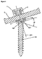
- Figures 1, 2, and 3 represent in a top view an implant with moving head and osseous anchorage by threading in cross section longitudinal to the bar, and in side view along the axis of the bar and in a top view, respectively;
- Figure 4 represents a partial side view of an implant not according to the invention with fixed head during introduction of the bar, in section transverse to the bar;
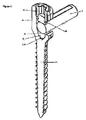
- Figures 5 and 6 represent perspective views of an implant not according to the invention with fixed head and osseous anchorage through screw in longitudinal section, along the axis of the bar, and transverse to the bar, respectively;
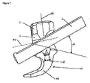
- Figure 7 represents a perspective view of an implant with fixed head not according to the invention but with osseous anchorage by hook, in longitudinal section along the axis of the bar and represented without its clamping means;
- Figures 8 and 9 represent, respectively, a perspective view and a sectional view of an implant with fixed head not according to the invention but according to a second embodiment of the moving baseplate;
- Figures 10 and 11 represent, respectively, a perspective view and a sectional view of an implant with fixed head not according to the invention but according to a third embodiment of the moving baseplate;
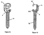
- Figures 12 and 13 represent, respectively, a perspective view and a sectional view of an implant with fixed head not according to the invention but according to a fourth embodiment of the moving baseplate.
- The invention described herein relates to an implant comprising on the one hand means for fixation of a bar and on the other hand means for anchoring to an osseous element.
- In a general fashion, in the field of surgery, an implant is defined as an object intended for being implanted in the human or animal body and to remain there continuously after the surgical procedure, at least over a certain period of time. More precisely, one speaks of a prosthesis to designate a device realizing a function, for example a movement or an articulation. Although not comprising a prosthesis per se, it must be understood that the implant described herein can comprise part of a prosthesis device or can be used for fixation on such a device.
- By way of example, the implant according to the invention is described herein in the form of an implant incorporated in an osteosynthesis device, such as used to hold, prop, or straighten the rachis. This function is thus assured by one or a plurality of rigid bars or similar elements, connecting a plurality of rachis elements with each other, such as the sacrum, the vertebrae or parts of vertebrae. In the same sense, such a bar can obviously be used also to connect another implant or prosthesis to the skeleton such as, for example, an artificial vertebra, an arthrodesis frame, or an intervertebral disc prosthesis.
- In its part affixed to an osseous element, said bar is anchored to said osseous element by means of one or a plurality of implants comprising osseous anchoring means such as, for example, a screw or one or a plurality of hooks. The implants thus comprise fixation means capable of receiving the bar before or in the course of the surgical procedure, then fixing said bar to the implant.
- In one embodiment represented in Figures 1 to 4 and in the examples represented in figures 5 and 6, said anchoring means are realized by an elongated part having a thread and capable of being screwed into the osseous material, for example at the pedicle or body of a vertebra or into the sacrum.
- In one embodiment represented in Figure 7, said osseous anchoring means comprise a hook intended for being engaged to a formal irregularity in the osseous element, such as a pedicle or a vertebral or sacral protrusion, or a transverse apophysis.
- In the course of the surgical procedure, when an implant is anchored in an osseous element and that a bar is to be fixed to it, the position in which the bar can be introduced does not always correspond to that, which would be the easiest for assembly to the fixation means of the implant. Said position can be restricted, for example, by the anatomical environment or by the fact that said bar is already assembled in another implant.
- Moreover, when the bar is inserted into the fixation means, if the latter are not properly aligned with the axis of the bar, the arrangement of the contact or fixation surfaces can be the cause of poor fixation, not being sufficiently rigid or secure.
- In particular, if the bar must be forced at the time of fixation to be adapted to the relative position of the implants, said force can result in residual stresses in the structure of the osteosynthesis device. Such persisting stresses can consequently impair the patient's daily comfort or perturb or change the desired effect of the device.
- In order that the fixation means can be better adjusted to the position of the bar, the fixation means according to the invention comprise at least one element having a certain moveability. Said element can be adjusted by a rotation around one or a plurality of axes not merged with the longitudinal axis of the bar and, for example, perpendicular to said longitudinal axis. Said rotation can be executed according to a determined clearance capable of comprising maximal angular positions or according to predetermined angular positions or capable of being unlimited, that is completely free. According to the embodiments, said fixation means can comprise an element moving along one or a plurality of axes or they may comprise a plurality of elements themselves moving along one or a plurality of axes.
- The bar can thus be assembled in a plurality of angular positions relative to the anchoring means or to the osseous element. These variations in angular position can particularly comprise an adjustable tilt relative to the osseous surface where the implant is anchored or a rotation around an axis extending from said osseous surface or a combination of the two.
- In the embodiments represented herein, the implant (1) is rigidly connected to the bar (2) by fixation means comprising a channel (12) housed in one part of the implant, said part being designated as the fixation head (11). The channel (12) can exhibit the shape of a channel opening at its two ends and open on one of its sides. Such a lateral opening (120) thus enables introduction (i; Figure 4) of the bar (2) through the side of the channel without the necessity of having to thread the bar through an end.
- Once inserted into the channel (12), fixation of the bar is assured by clamping means (4) that are supported by means of at least one side of said bar to make contact and block it against one wall, called the support wall, of the channel (12). Said clamping means comprise, for example, a clamping screw (41) mounted in a drilling (14) borne by one part of the fixation head (11) constituting one edge (124) of the lateral opening (120) of the channel (12). Said clamping screw (41) has an external threading that co-operates with an internal threading of this drilling (14) to displace the screw (41) along a clamping axis (d4) and bring it into contact against the bar, thus clamping clamping screw (41) can comprise formal irregularities, for example an internal mark, enabling the use of a clamping tool to realize blocking the bar (2). The bar can advantageously have one or a plurality of flats upon its external surface to enable obtaining a flat contact surface with the clamping screw (41) and thus enhanced reliability of blocking than with a punctal or linear contact.
- In the embodiments represented in Figures 4 to 13, the channel (12) has a support wall providing an element, called a moving baseplate (3), said baseplate being moving relative to the fixation head (11). Said moving baseplate (3) has a part (31) in form of a sphere portion, leaning by a complementary contact in a housing formed in the wall of the channel (12). By virtue of said spherical contact, the moving baseplate (3) disposes of a certain freedom of rotation around the center of its spherical part (31). Said moving baseplate has in particular a certain clearance (a3) in rotation around an axis (d3) substantially perpendicular to the longitudinal axis (d12) of the channel and to the direction of support of the clamping means. On its face, called support face (32), at the contact with the bar, the moving baseplate has a shape complementary to the external surface of said bar, for example in the form of a cylindrical portion, that provides a good contact surface when clamping.
- On its part (31) in form of a sphere portion the moving baseplate (3) can have one or a plurality of formal irregularities (310) co-operating with one or a plurality of formal irregularities of the housing of the fixation head (11) to form a stop limiting the clearance in rotation of the moving baseplate. Said formal irregularities (310) can be, for example, a pin protuding from the moving baseplate and co-operating with a larger dimensioned cavity formed on the complementary contact surface. Said stop, for example, allows avoiding excessive turning of the moving baseplate and assuring that it properly presents its support face facing the bar.
- With regard to the bar (2), the inside surface of the channel (12) is of sufficient dimensions to enable the bar a certain clearance (a2) in rotation around one or a plurality of axes not parallel to the longitudinal axis of the bar or, in particular, perpendicular to this longitudinal axis.
- At its end on the bar side, the clamping screw (41) exhibits a moving element, called the support head (42), articulated by a ball and socket connection. The screwing of the clamping screw (41) provokes the leaning of said support head (42) on the flat of the bar (2) through one moving clamping face (420). Said ball and socket connection allows a certain clearance of the support head (42) relative to the clamping screw (41) in rotation around the center of said ball and socket connection. By a rotation around at least one axis parallel to the axis of rotation (d3) of the moving baseplate (3), the moving support face (420) can thus be permanently adjusted to the position of the bar and the moving baseplate. Said ball and socket connection also enables the support face to remain in contact with the bar without sliding over it, which avoids deterioration of the surfaces in contact, assures the blockage, and reduces the risk of residual stresses. The examples shown in the figures 4 to 13 may of course be combined with the embodiments shown in figures 1 to 3, because to articulation of the osseous anchoring means relative to the head is fully compatible with the ball and socket connection and/or with the stops of the moving baseplate and so one. The various possible combinations of the examples shown with the embodiment in which the osseous anchoring is articulated relative to the fixation head should thus be considered as part of the invention.
- Thus, it can be understood, that the bar can be inserted and blocked in different angular positions inside the channel (12), while providing a flat contact surface both with the clamping means and with the wall of the channel by means of the moving baseplate (3). Said polyaxial angular clearance thus allows inserting the bar more easily and obtaining a clamping of the bar in its most natural position relative to the implants, which reduces or eliminates the stresses that could subsist in the device after clamping. Furthermore, the clamping forces concur directly with blocking without necessarily opposing the rigidity of the bar and the reliability of the blocking is thus improved.
- In an embodiment represented in Figures 1 to 3, the fixation head (11) is moving relative to the osseous anchoring part (10) according to an articulation enabling freedom in rotation around at least two axes not merged with the longitudinal axis of the bar.
- This articulation is realized by a complementary spherical contact between the fixation head (11) and the end of the osseous anchorage part (10) remote from the osseous element, said end being designated as the rotation head (101). The rotation head comprises a part (1011) in form of a hemispherical portion widening in the direction of the fixation head (11); that is, by moving away from the osseous element. Said hemispherical portion(1011) is retained on the inside of the fixation head (11) by a complementary contact in a housing formed in said fixation head and narrowing towards the osseous anchorage part. Said housing communicates with the channel (12) where it opens in its part situated opposite to the clamping means. The spherical nature of these contact surfaces thus enable a rotation of the fixation head and the osseous anchorage part relative to each other, in rotation about the center of said surface (1011) in a hemispherical form.
- Said rotations enable, in particular, unlimited clearance (a1) of the fixation head relative to the osseous anchorage part, in rotation around an axis (d11), called the axis of rotation of the head, non parallel, indeed even perpendicular to the longitudinal axis of the bar or of the channel and passing through the center of the hemisphere (1011) of the rotation head (101).
- These rotations also enable a certain clearance (a4) of the fixation head relative to the osseous anchorage part, in rotation around an axis substantially perpendicular to the axis (d11) of rotation of the head and passing through the center of the hemisphere (1011) of the rotation head (101).
- In this embodiment, a moving base (3) similar to that hereinbefore described is borne by the rotation head (101) in a housing formed on the face opposite to the bar.
- At the time of clamping of the clamping means, the clamping screw (41) co-operates by its threading with the drilling (14) of the fixation head (11) to lean on the bar (2). The bar leans on the moving baseplate (3). The moving baseplate (3) leans on the rotation head (101), which is retained by the housing of the fixation head (11). Clamping of the clamping means leads to a leaning of whole these surfaces among themselves, which produces a blocking of the set of these parts relative to each other.
- It is well understood that in this manner an implant is provided, whose fixation head, prior to blocking of the clamping means, is moving relative to the osseous anchoring part, while being fixed to the bar after said blockage. The fixation head (11) can thus be tilted according to a certain clearance relative to the exterior surface of the osseous element and can pivot freely around an axis extending from said osseous surface.
- Once the implant is anchored in the osseous element, it is thus still possible to adjust the position of the fixation head in order to enable the bar to keep or to resume its shape, which reduces the risks of residual stresses and permits easy introduction of the bar into diverse positions of this bar and implants. Once the bar is introduced and the whole device assembled, it is thus possible to block said positions by virtue of the clamping means. As clamping can be achieved in the most natural position of the pin, the clamping forces are concentrated at the best on the blocking reliability. In particular, these clamping forces do not risk, or the risk thereof is minimal, introducing in the device residual stresses or movements relative to the position selected by the surgeon.
- In this embodiment, the clamping means (4) need not comprise a support head (42) on the ball and socket connection, in particular if the tilting of the fixation head (11) is sufficiently close to that of the bar (2) to assure a planar contact between the clamping screw (41) and the flat of the bar.
- It should be clear to the those skilled in the art that the present invention enables embodiments in many specific forms without moving it away from the field of application of the invention as claimed. Consequently, the present embodiments must be considered illustrative, but can be modified in the field defined by the scope of the attached claims and the invention should not be limited to the details provided above.
Claims (17)
- An implant (1) for osseous anchoring comprising fixation means capable of receiving and fixing at least one bar (2), in particular of osteosynthesis, the implant (1) comprising on the one hand osseous anchoring means (10) and on the other hand a fixation head (11) bearing the 5 fixation means, the fixation head being traversed by at least one channel (12) receiving the bar (2) and comprising clamping means (4) capable of clamping the bar against one inside wall, called support wall (32), the clamping means (4) and said support wall (32) enable obtaining, prior to blocking of the fixation, a determined clearance in rotation around at least one first axis (d3) not parallel to the longitudinal axis of the bar, the clamping means comprise a face at the contact with the bar, called the moving clamping face (120), the moving clamping face (420) of the clamping means (4) being borne by a support head (42) articulated at the end of the clamping means (4) by a ball and socket connection, the implant (1) being characterized in that the channel (12) has the form of an open channel having an aperture (120) opening onto on of the lateral faces of the fixation head (11), one edge (124) of said aperture bearing the clamping means (4), the aperture (120) of the channel and the position of the clamping means thus enabling the introduction (i) of the bar by the lateral route, in that the clamping means (4) and said support wall (32) enable obtaining, prior to blocking of the fixation, a determined clearance in rotation around at least one second axis (d4) not parallel to the first axis (d3) and not parallel to the longitudinal axis of the bar and in that the fixation head (11) is moving relative to the osseous anchoring part (10) according to an articulation enabling freedom in rotation around at least two axes mot merged with the longitudinal axis of the bar.
- An implant according to claim 1, wherein the articulation between the fixation head (11) and the osseous anchoring part providing freedom of rotation consist in a rotation head (101) at an extremity of the osseous anchoring part (10), the fixation head being movable relating to this rotation head, at least prior the blocking of the clamping means.
- An implant according to claim 2, wherein the fixation head (11) presents relating to the rotation head (101) on the one hand an unlimited clearance (a1) in rotation around an axis, called head rotation axis (d11), not parallel to the channel axis (12) or to the longitudinal axis of the bar.
- An implant according to claim 3, wherein the fixation head (11) presents relating to the rotation head (101) a determined clearance (a4) in rotation around an axis, called head tilting axis (d101), not parallel to the head rotation axis (d11).
- An implant according to anyone of claims 2 to 4, wherein the clamping means (4) bear the bar (2) on a moving baseplate (3) comprising sphere portion part (31), this sphere portion bearing in a complementary housing formed in the rotation head (101), the rotation head itself comprising an external rotation surface (1011) in form of a half sphere portion bellmouthed toward the fixation head (11), this external rotation surface (1011) being retained in a housing having a complementary shape prepared in the fixation head (11), the clamping of the clamping means (4) inside the fixation head leading thus to a clamping and stopping of all of these complementary surfaces being in contact.
- An implant according to anyone of claims 1 to 5, wherein the channel (12) opens at each side of the fixation head (11) through apertures whose disposition and dimensions enable to the bar a determined clearance (a2) inside the channel (12) in rotation at least around one axis that is substantially perpendicular to the axis (d12) of the channel and to the support direction (d4) of the clamping means.
- An implant according to anyone of claims 1 to 6, wherein the support wall comprises an element, called the moving baseplate (3), having a clearance (a3) in rotation at least around one axis (d3) not parallel to the axis (d12) of the channel (12) and to the support direction (d4) of the clamping means on the bar (2), the clamping means comprising a face at the contact with the bar, called moving clamping face (420), having a determined clearance in rotation around one axis substantially parallel to the axis (d3) of rotation of the moving baseplate.
- An implant according to claim 7, wherein the moving baseplate (3) has a part in form of a sphere portion (31) leaning by a complementary contact in a housing formed in the fixation head (11).
- An implant according to anyone of claims 1 to 8, wherein the moving baseplate (3) is in contact with the bar (2) by a support face (32) having a shape substantially complementary to the exterior shape of the bar, the moving baseplate having at least one formal irregularity (310) co-operating with a formal irregularity (130) borne by the fixation head (11) to form a stop holding the support face (32) of the baseplate turned towards the side of the bar (2).
- An implant according to Claim 9, wherein the formal irregularity (310) is a pin formed on the underside, the rear or on the front of the moving baseplate (3), co-operating with a cavity with a greater dimension borne by the fixation head.
- An implant according to Claim 9, wherein the formal irregularity (310) is a cylindrical drilling formed on the front of the moving baseplate (3) and co-operating with the cylindrical head of a pin held in the drilling formed in the fixation head (11).
- An implant according to anyone of claims 1 to 11, wherein the channel (12) is in form of an open channel with a lateral opening (120), opening towards one of the facts of the fixation head (11), one edge (124) of this opening carrying the clamping means (4), the channel opening (120) and the position of the clamping means thus allowing the introduction (i) of the bar by a lateral route.
- An implant according to anyone of claims 1 to 12, wherein the clamping means (4) comprise a clamping screw (41) inserted into a drilling (14) traversing one edge (124) of the channel opening and co-operating with said drilling to realize a support upon the bar (2).
- An implant according to anyone of claims 1 to 13, wherein the osseous anchoring means comprise either a threaded part (102) capable of anchoring in an osseous element by co-operation with the osseous material of said osseous element, or a protruding part (103) capable of anchoring at the surface of an osseous element by co-operating with at least one formal irregularity of said same surface.
- An implant according to claim 14, wherein the osseous anchoring means are realized by an elongated and threaded part, the axis (d12) of the channel (12) being substantially perpendicular to the longitudinal axis of the osseous anchoring means.
- An implant according to anyone of claims 1 to 15, wherein the channel (d12) has a shape comprising two head to tail truncated cones facing each other with their minor baseplates and joined to each other directly or by means of a cylindrical part.
- An implant according to anyone of Claims 1 to 16, wherein the bar (2) bears one or a plurality of flats on its external surface, providing a flat contact surface with the support head (42).
Applications Claiming Priority (2)
| Application Number | Priority Date | Filing Date | Title |
|---|---|---|---|
| FR0116122A FR2833151B1 (en) | 2001-12-12 | 2001-12-12 | BONE ANCHORING IMPLANT WITH POLYAXIAL HEAD |
| EP02788326A EP1453429B1 (en) | 2001-12-12 | 2002-12-12 | Implant for osseous anchoring with polyaxial head |
Related Parent Applications (1)
| Application Number | Title | Priority Date | Filing Date |
|---|---|---|---|
| EP02788326A Division EP1453429B1 (en) | 2001-12-12 | 2002-12-12 | Implant for osseous anchoring with polyaxial head |
Publications (2)
| Publication Number | Publication Date |
|---|---|
| EP1656897A1 true EP1656897A1 (en) | 2006-05-17 |
| EP1656897B1 EP1656897B1 (en) | 2009-09-23 |
Family
ID=8870441
Family Applications (2)
| Application Number | Title | Priority Date | Filing Date |
|---|---|---|---|
| EP05292677A Expired - Lifetime EP1656897B1 (en) | 2001-12-12 | 2002-12-12 | Implant for osseus anchoring with polyaxial head |
| EP02788326A Expired - Lifetime EP1453429B1 (en) | 2001-12-12 | 2002-12-12 | Implant for osseous anchoring with polyaxial head |
Family Applications After (1)
| Application Number | Title | Priority Date | Filing Date |
|---|---|---|---|
| EP02788326A Expired - Lifetime EP1453429B1 (en) | 2001-12-12 | 2002-12-12 | Implant for osseous anchoring with polyaxial head |
Country Status (18)
| Country | Link |
|---|---|
| US (5) | US20050107788A1 (en) |
| EP (2) | EP1656897B1 (en) |
| JP (1) | JP4227020B2 (en) |
| KR (1) | KR100968836B1 (en) |
| CN (1) | CN1287747C (en) |
| AT (2) | ATE443484T1 (en) |
| AU (1) | AU2002353305B2 (en) |
| BR (1) | BRPI0214793B1 (en) |
| CA (1) | CA2469260C (en) |
| DE (2) | DE60210502T2 (en) |
| DK (2) | DK1656897T3 (en) |
| ES (2) | ES2330760T3 (en) |
| FR (1) | FR2833151B1 (en) |
| MX (1) | MXPA04005660A (en) |
| PT (2) | PT1656897E (en) |
| RU (1) | RU2302839C2 (en) |
| WO (1) | WO2003049629A1 (en) |
| ZA (1) | ZA200404545B (en) |
Families Citing this family (182)
| Publication number | Priority date | Publication date | Assignee | Title |
|---|---|---|---|---|
| FR2897259B1 (en) | 2006-02-15 | 2008-05-09 | Ldr Medical Soc Par Actions Si | INTERSOMATIC TRANSFORAMINAL CAGE WITH INTERBREBAL FUSION GRAFT AND CAGE IMPLANTATION INSTRUMENT |
| US7833250B2 (en) | 2004-11-10 | 2010-11-16 | Jackson Roger P | Polyaxial bone screw with helically wound capture connection |
| US8377100B2 (en) | 2000-12-08 | 2013-02-19 | Roger P. Jackson | Closure for open-headed medical implant |
| US6726689B2 (en) | 2002-09-06 | 2004-04-27 | Roger P. Jackson | Helical interlocking mating guide and advancement structure |
| FR2823095B1 (en) * | 2001-04-06 | 2004-02-06 | Ldr Medical | RACHIS OSTEOSYNTHESIS DEVICE AND PLACEMENT METHOD |
| FR2824261B1 (en) | 2001-05-04 | 2004-05-28 | Ldr Medical | INTERVERTEBRAL DISC PROSTHESIS AND IMPLEMENTATION METHOD AND TOOLS |
| US10258382B2 (en) | 2007-01-18 | 2019-04-16 | Roger P. Jackson | Rod-cord dynamic connection assemblies with slidable bone anchor attachment members along the cord |
| US7862587B2 (en) | 2004-02-27 | 2011-01-04 | Jackson Roger P | Dynamic stabilization assemblies, tool set and method |
| US8292926B2 (en) | 2005-09-30 | 2012-10-23 | Jackson Roger P | Dynamic stabilization connecting member with elastic core and outer sleeve |
| US10729469B2 (en) | 2006-01-09 | 2020-08-04 | Roger P. Jackson | Flexible spinal stabilization assembly with spacer having off-axis core member |
| US8353932B2 (en) | 2005-09-30 | 2013-01-15 | Jackson Roger P | Polyaxial bone anchor assembly with one-piece closure, pressure insert and plastic elongate member |
| FR2831049B1 (en) | 2001-10-18 | 2004-08-13 | Ldr Medical | PLATE FOR OSTEOSYNTHESIS DEVICE AND PRE-ASSEMBLY METHOD |
| FR2831048B1 (en) | 2001-10-18 | 2004-09-17 | Ldr Medical | PROGRESSIVE APPROACH OSTEOSYNTHESIS DEVICE AND PRE-ASSEMBLY PROCESS |
| FR2833151B1 (en) | 2001-12-12 | 2004-09-17 | Ldr Medical | BONE ANCHORING IMPLANT WITH POLYAXIAL HEAD |
| US8257402B2 (en) | 2002-09-06 | 2012-09-04 | Jackson Roger P | Closure for rod receiving orthopedic implant having left handed thread removal |
| US8282673B2 (en) | 2002-09-06 | 2012-10-09 | Jackson Roger P | Anti-splay medical implant closure with multi-surface removal aperture |
| US8876868B2 (en) | 2002-09-06 | 2014-11-04 | Roger P. Jackson | Helical guide and advancement flange with radially loaded lip |
| FR2846550B1 (en) | 2002-11-05 | 2006-01-13 | Ldr Medical | INTERVERTEBRAL DISC PROSTHESIS |
| US7887539B2 (en) | 2003-01-24 | 2011-02-15 | Depuy Spine, Inc. | Spinal rod approximators |
| US7141051B2 (en) * | 2003-02-05 | 2006-11-28 | Pioneer Laboratories, Inc. | Low profile spinal fixation system |
| US8540753B2 (en) | 2003-04-09 | 2013-09-24 | Roger P. Jackson | Polyaxial bone screw with uploaded threaded shank and method of assembly and use |
| US7621918B2 (en) | 2004-11-23 | 2009-11-24 | Jackson Roger P | Spinal fixation tool set and method |
| US6716214B1 (en) | 2003-06-18 | 2004-04-06 | Roger P. Jackson | Polyaxial bone screw with spline capture connection |
| US7377923B2 (en) | 2003-05-22 | 2008-05-27 | Alphatec Spine, Inc. | Variable angle spinal screw assembly |
| US8366753B2 (en) | 2003-06-18 | 2013-02-05 | Jackson Roger P | Polyaxial bone screw assembly with fixed retaining structure |
| US8926670B2 (en) | 2003-06-18 | 2015-01-06 | Roger P. Jackson | Polyaxial bone screw assembly |
| US7766915B2 (en) | 2004-02-27 | 2010-08-03 | Jackson Roger P | Dynamic fixation assemblies with inner core and outer coil-like member |
| US8398682B2 (en) | 2003-06-18 | 2013-03-19 | Roger P. Jackson | Polyaxial bone screw assembly |
| US7967850B2 (en) | 2003-06-18 | 2011-06-28 | Jackson Roger P | Polyaxial bone anchor with helical capture connection, insert and dual locking assembly |
| US8377102B2 (en) | 2003-06-18 | 2013-02-19 | Roger P. Jackson | Polyaxial bone anchor with spline capture connection and lower pressure insert |
| US8092500B2 (en) | 2007-05-01 | 2012-01-10 | Jackson Roger P | Dynamic stabilization connecting member with floating core, compression spacer and over-mold |
| US8257398B2 (en) | 2003-06-18 | 2012-09-04 | Jackson Roger P | Polyaxial bone screw with cam capture |
| US7776067B2 (en) | 2005-05-27 | 2010-08-17 | Jackson Roger P | Polyaxial bone screw with shank articulation pressure insert and method |
| US8137386B2 (en) | 2003-08-28 | 2012-03-20 | Jackson Roger P | Polyaxial bone screw apparatus |
| FR2859095B1 (en) | 2003-09-01 | 2006-05-12 | Ldr Medical | BONE ANCHORING IMPLANT WITH A POLYAXIAL HEAD AND METHOD OF PLACING THE IMPLANT |
| EP1663032A1 (en) * | 2003-09-26 | 2006-06-07 | Synthes GmbH | Device for connecting a longitudinal carrier to a bone |
| US7967826B2 (en) * | 2003-10-21 | 2011-06-28 | Theken Spine, Llc | Connector transfer tool for internal structure stabilization systems |
| US7588575B2 (en) | 2003-10-21 | 2009-09-15 | Innovative Spinal Technologies | Extension for use with stabilization systems for internal structures |
| US7179261B2 (en) | 2003-12-16 | 2007-02-20 | Depuy Spine, Inc. | Percutaneous access devices and bone anchor assemblies |
| US11419642B2 (en) | 2003-12-16 | 2022-08-23 | Medos International Sarl | Percutaneous access devices and bone anchor assemblies |
| US7527638B2 (en) | 2003-12-16 | 2009-05-05 | Depuy Spine, Inc. | Methods and devices for minimally invasive spinal fixation element placement |
| FR2865629B1 (en) | 2004-02-04 | 2007-01-26 | Ldr Medical | INTERVERTEBRAL DISC PROSTHESIS |
| ES2547532T3 (en) | 2004-02-04 | 2015-10-07 | Ldr Medical | Intervertebral disc prosthesis |
| US11241261B2 (en) | 2005-09-30 | 2022-02-08 | Roger P Jackson | Apparatus and method for soft spinal stabilization using a tensionable cord and releasable end structure |
| WO2005092218A1 (en) | 2004-02-27 | 2005-10-06 | Jackson Roger P | Orthopedic implant rod reduction tool set and method |
| US8152810B2 (en) | 2004-11-23 | 2012-04-10 | Jackson Roger P | Spinal fixation tool set and method |
| US7160300B2 (en) | 2004-02-27 | 2007-01-09 | Jackson Roger P | Orthopedic implant rod reduction tool set and method |
| FR2869528B1 (en) | 2004-04-28 | 2007-02-02 | Ldr Medical | INTERVERTEBRAL DISC PROSTHESIS |
| US7651502B2 (en) | 2004-09-24 | 2010-01-26 | Jackson Roger P | Spinal fixation tool set and method for rod reduction and fastener insertion |
| US8926672B2 (en) | 2004-11-10 | 2015-01-06 | Roger P. Jackson | Splay control closure for open bone anchor |
| JP2008519656A (en) | 2004-11-10 | 2008-06-12 | ロジャー・ピー・ジャクソン | Helical guide and forward flange with break extension |
| US9393047B2 (en) | 2009-06-15 | 2016-07-19 | Roger P. Jackson | Polyaxial bone anchor with pop-on shank and friction fit retainer with low profile edge lock |
| US7875065B2 (en) | 2004-11-23 | 2011-01-25 | Jackson Roger P | Polyaxial bone screw with multi-part shank retainer and pressure insert |
| US8556938B2 (en) | 2009-06-15 | 2013-10-15 | Roger P. Jackson | Polyaxial bone anchor with non-pivotable retainer and pop-on shank, some with friction fit |
| US9168069B2 (en) | 2009-06-15 | 2015-10-27 | Roger P. Jackson | Polyaxial bone anchor with pop-on shank and winged insert with lower skirt for engaging a friction fit retainer |
| US9980753B2 (en) | 2009-06-15 | 2018-05-29 | Roger P Jackson | pivotal anchor with snap-in-place insert having rotation blocking extensions |
| US8444681B2 (en) | 2009-06-15 | 2013-05-21 | Roger P. Jackson | Polyaxial bone anchor with pop-on shank, friction fit retainer and winged insert |
| US9216041B2 (en) | 2009-06-15 | 2015-12-22 | Roger P. Jackson | Spinal connecting members with tensioned cords and rigid sleeves for engaging compression inserts |
| WO2006057837A1 (en) | 2004-11-23 | 2006-06-01 | Jackson Roger P | Spinal fixation tool attachment structure |
| US8308782B2 (en) | 2004-11-23 | 2012-11-13 | Jackson Roger P | Bone anchors with longitudinal connecting member engaging inserts and closures for fixation and optional angulation |
| EP1814474B1 (en) | 2004-11-24 | 2011-09-14 | Samy Abdou | Devices for inter-vertebral orthopedic device placement |
| FR2879436B1 (en) | 2004-12-22 | 2007-03-09 | Ldr Medical | INTERVERTEBRAL DISC PROSTHESIS |
| US10076361B2 (en) | 2005-02-22 | 2018-09-18 | Roger P. Jackson | Polyaxial bone screw with spherical capture, compression and alignment and retention structures |
| US7901437B2 (en) | 2007-01-26 | 2011-03-08 | Jackson Roger P | Dynamic stabilization member with molded connection |
| US7951172B2 (en) | 2005-03-04 | 2011-05-31 | Depuy Spine Sarl | Constrained motion bone screw assembly |
| US7951175B2 (en) | 2005-03-04 | 2011-05-31 | Depuy Spine, Inc. | Instruments and methods for manipulating a vertebra |
| US20060235385A1 (en) * | 2005-03-31 | 2006-10-19 | Dale Whipple | Low profile polyaxial screw |
| FR2887762B1 (en) | 2005-06-29 | 2007-10-12 | Ldr Medical Soc Par Actions Si | INTERVERTEBRAL DISC PROSTHESIS INSERTION INSTRUMENTATION BETWEEN VERTEBRATES |
| CH701479B1 (en) * | 2005-09-13 | 2011-01-31 | Bird Biedermann Ag | Vertebral column implant, has connecting unit, which is clamped by clamping structure in form-fit manner between retainer and spacer, where clamping is strengthened under increased axial force of elastic bar |
| FR2891135B1 (en) | 2005-09-23 | 2008-09-12 | Ldr Medical Sarl | INTERVERTEBRAL DISC PROSTHESIS |
| US8105368B2 (en) | 2005-09-30 | 2012-01-31 | Jackson Roger P | Dynamic stabilization connecting member with slitted core and outer sleeve |
| US7722651B2 (en) | 2005-10-21 | 2010-05-25 | Depuy Spine, Inc. | Adjustable bone screw assembly |
| GB0521582D0 (en) * | 2005-10-22 | 2005-11-30 | Depuy Int Ltd | An implant for supporting a spinal column |
| FR2893838B1 (en) | 2005-11-30 | 2008-08-08 | Ldr Medical Soc Par Actions Si | PROSTHESIS OF INTERVERTEBRAL DISC AND INSTRUMENTATION OF INSERTION OF THE PROSTHESIS BETWEEN VERTEBRATES |
| WO2007064324A1 (en) * | 2005-12-01 | 2007-06-07 | Warsaw Orthopedic, Inc. | Side-loading adjustable bone anchor |
| US20070161986A1 (en) * | 2005-12-13 | 2007-07-12 | Levy Mark M | Polyaxial fastener assembly |
| US7704271B2 (en) | 2005-12-19 | 2010-04-27 | Abdou M Samy | Devices and methods for inter-vertebral orthopedic device placement |
| GB0600662D0 (en) * | 2006-01-13 | 2006-02-22 | Depuy Int Ltd | Spinal support rod kit |
| US8348952B2 (en) | 2006-01-26 | 2013-01-08 | Depuy International Ltd. | System and method for cooling a spinal correction device comprising a shape memory material for corrective spinal surgery |
| WO2007118179A2 (en) * | 2006-04-06 | 2007-10-18 | Synthes (U.S.A.) | Remotely adjustable tissue displacement device |
| US20080058808A1 (en) | 2006-06-14 | 2008-03-06 | Spartek Medical, Inc. | Implant system and method to treat degenerative disorders of the spine |
| JP5210305B2 (en) * | 2006-06-16 | 2013-06-12 | アルファテック スパイン, インコーポレイテッド | Spinal screw assembly system, system for implanting spinal screw assembly |
| US20080058805A1 (en) * | 2006-08-28 | 2008-03-06 | Microdexterity Systems, Inc. | Spinal fusion implant |
| CA2670988C (en) | 2006-12-08 | 2014-03-25 | Roger P. Jackson | Tool system for dynamic spinal implants |
| FR2910267B1 (en) * | 2006-12-21 | 2009-01-23 | Ldr Medical Soc Par Actions Si | VERTEBRAL SUPPORT DEVICE |
| US8366745B2 (en) | 2007-05-01 | 2013-02-05 | Jackson Roger P | Dynamic stabilization assembly having pre-compressed spacers with differential displacements |
| US8475498B2 (en) | 2007-01-18 | 2013-07-02 | Roger P. Jackson | Dynamic stabilization connecting member with cord connection |
| US10792074B2 (en) | 2007-01-22 | 2020-10-06 | Roger P. Jackson | Pivotal bone anchor assemly with twist-in-place friction fit insert |
| US8012177B2 (en) | 2007-02-12 | 2011-09-06 | Jackson Roger P | Dynamic stabilization assembly with frusto-conical connection |
| US8465546B2 (en) | 2007-02-16 | 2013-06-18 | Ldr Medical | Intervertebral disc prosthesis insertion assemblies |
| US10383660B2 (en) | 2007-05-01 | 2019-08-20 | Roger P. Jackson | Soft stabilization assemblies with pretensioned cords |
| US7951173B2 (en) | 2007-05-16 | 2011-05-31 | Ortho Innovations, Llc | Pedicle screw implant system |
| US7942909B2 (en) | 2009-08-13 | 2011-05-17 | Ortho Innovations, Llc | Thread-thru polyaxial pedicle screw system |
| US7942911B2 (en) | 2007-05-16 | 2011-05-17 | Ortho Innovations, Llc | Polyaxial bone screw |
| US7947065B2 (en) * | 2008-11-14 | 2011-05-24 | Ortho Innovations, Llc | Locking polyaxial ball and socket fastener |
| US8197518B2 (en) | 2007-05-16 | 2012-06-12 | Ortho Innovations, Llc | Thread-thru polyaxial pedicle screw system |
| US7942910B2 (en) | 2007-05-16 | 2011-05-17 | Ortho Innovations, Llc | Polyaxial bone screw |
| CA2690038C (en) | 2007-05-31 | 2012-11-27 | Roger P. Jackson | Dynamic stabilization connecting member with pre-tensioned solid core |
| US8083772B2 (en) | 2007-06-05 | 2011-12-27 | Spartek Medical, Inc. | Dynamic spinal rod assembly and method for dynamic stabilization of the spine |
| US7635380B2 (en) | 2007-06-05 | 2009-12-22 | Spartek Medical, Inc. | Bone anchor with a compressor element for receiving a rod for a dynamic stabilization and motion preservation spinal implantation system and method |
| US8048115B2 (en) | 2007-06-05 | 2011-11-01 | Spartek Medical, Inc. | Surgical tool and method for implantation of a dynamic bone anchor |
| US7993372B2 (en) | 2007-06-05 | 2011-08-09 | Spartek Medical, Inc. | Dynamic stabilization and motion preservation spinal implantation system with a shielded deflection rod system and method |
| US8092501B2 (en) | 2007-06-05 | 2012-01-10 | Spartek Medical, Inc. | Dynamic spinal rod and method for dynamic stabilization of the spine |
| US8048121B2 (en) | 2007-06-05 | 2011-11-01 | Spartek Medical, Inc. | Spine implant with a defelction rod system anchored to a bone anchor and method |
| US8021396B2 (en) | 2007-06-05 | 2011-09-20 | Spartek Medical, Inc. | Configurable dynamic spinal rod and method for dynamic stabilization of the spine |
| US7985243B2 (en) | 2007-06-05 | 2011-07-26 | Spartek Medical, Inc. | Deflection rod system with mount for a dynamic stabilization and motion preservation spinal implantation system and method |
| US8114134B2 (en) | 2007-06-05 | 2012-02-14 | Spartek Medical, Inc. | Spinal prosthesis having a three bar linkage for motion preservation and dynamic stabilization of the spine |
| FR2916956B1 (en) | 2007-06-08 | 2012-12-14 | Ldr Medical | INTERSOMATIC CAGE, INTERVERTEBRAL PROSTHESIS, ANCHORING DEVICE AND IMPLANTATION INSTRUMENTATION |
| FR2918555B1 (en) * | 2007-07-12 | 2010-04-02 | Ldr Medical | DEVICE AND SYSTEM FOR TRANSVERSE SPINACH CONNECTION |
| ES2379287T3 (en) | 2007-10-11 | 2012-04-24 | Biedermann Motech Gmbh | Bone anchoring device |
| US8911477B2 (en) | 2007-10-23 | 2014-12-16 | Roger P. Jackson | Dynamic stabilization member with end plate support and cable core extension |
| GB0720762D0 (en) | 2007-10-24 | 2007-12-05 | Depuy Spine Sorl | Assembly for orthopaedic surgery |
| US8007522B2 (en) | 2008-02-04 | 2011-08-30 | Depuy Spine, Inc. | Methods for correction of spinal deformities |
| US8083775B2 (en) | 2008-02-26 | 2011-12-27 | Spartek Medical, Inc. | Load-sharing bone anchor having a natural center of rotation and method for dynamic stabilization of the spine |
| US8337536B2 (en) | 2008-02-26 | 2012-12-25 | Spartek Medical, Inc. | Load-sharing bone anchor having a deflectable post with a compliant ring and method for stabilization of the spine |
| US8007518B2 (en) | 2008-02-26 | 2011-08-30 | Spartek Medical, Inc. | Load-sharing component having a deflectable post and method for dynamic stabilization of the spine |
| US8016861B2 (en) | 2008-02-26 | 2011-09-13 | Spartek Medical, Inc. | Versatile polyaxial connector assembly and method for dynamic stabilization of the spine |
| US8097024B2 (en) | 2008-02-26 | 2012-01-17 | Spartek Medical, Inc. | Load-sharing bone anchor having a deflectable post and method for stabilization of the spine |
| US8057515B2 (en) | 2008-02-26 | 2011-11-15 | Spartek Medical, Inc. | Load-sharing anchor having a deflectable post and centering spring and method for dynamic stabilization of the spine |
| US8211155B2 (en) | 2008-02-26 | 2012-07-03 | Spartek Medical, Inc. | Load-sharing bone anchor having a durable compliant member and method for dynamic stabilization of the spine |
| US8333792B2 (en) | 2008-02-26 | 2012-12-18 | Spartek Medical, Inc. | Load-sharing bone anchor having a deflectable post and method for dynamic stabilization of the spine |
| US8267979B2 (en) | 2008-02-26 | 2012-09-18 | Spartek Medical, Inc. | Load-sharing bone anchor having a deflectable post and axial spring and method for dynamic stabilization of the spine |
| US8608746B2 (en) | 2008-03-10 | 2013-12-17 | DePuy Synthes Products, LLC | Derotation instrument with reduction functionality |
| US10973556B2 (en) | 2008-06-17 | 2021-04-13 | DePuy Synthes Products, Inc. | Adjustable implant assembly |
| JP2012529969A (en) | 2008-08-01 | 2012-11-29 | ロジャー・ピー・ジャクソン | Longitudinal connecting member with tensioning cord with sleeve |
| US9408715B2 (en) | 2009-04-15 | 2016-08-09 | DePuy Synthes Products, Inc. | Arcuate fixation member |
| US8641766B2 (en) | 2009-04-15 | 2014-02-04 | DePuy Synthes Products, LLC | Arcuate fixation member |
| EP2757988A4 (en) | 2009-06-15 | 2015-08-19 | Jackson Roger P | Polyaxial bone anchor with pop-on shank and winged insert with friction fit compressive collet |
| US11229457B2 (en) | 2009-06-15 | 2022-01-25 | Roger P. Jackson | Pivotal bone anchor assembly with insert tool deployment |
| US8998959B2 (en) | 2009-06-15 | 2015-04-07 | Roger P Jackson | Polyaxial bone anchors with pop-on shank, fully constrained friction fit retainer and lock and release insert |
| US9668771B2 (en) | 2009-06-15 | 2017-06-06 | Roger P Jackson | Soft stabilization assemblies with off-set connector |
| US9211144B2 (en) * | 2009-09-09 | 2015-12-15 | Globus Medical, Inc. | Spine surgery device and method |
| US20110106181A1 (en) * | 2009-10-30 | 2011-05-05 | Warsaw Orthopedic, Inc. | Adjustable saddle for a bone anchor |
| US8430917B2 (en) * | 2009-10-30 | 2013-04-30 | Warsaw Orthopedic, Inc. | Bone engaging implant with adjustment saddle |
| CN102695465A (en) | 2009-12-02 | 2012-09-26 | 斯帕泰克医疗股份有限公司 | Low profile spinal prosthesis incorporating a bone anchor having a deflectable post and a compound spinal rod |
| US8764806B2 (en) | 2009-12-07 | 2014-07-01 | Samy Abdou | Devices and methods for minimally invasive spinal stabilization and instrumentation |
| US9833331B2 (en) | 2009-12-31 | 2017-12-05 | Ldr Medical | Anchoring device and system for an intervertebral implant, intervertebral implant and implantation instrument |
| US8518085B2 (en) | 2010-06-10 | 2013-08-27 | Spartek Medical, Inc. | Adaptive spinal rod and methods for stabilization of the spine |
| US8377139B2 (en) | 2010-06-17 | 2013-02-19 | Aesculap Implant Systems, Llc | Standalone interbody fusion device with locking and release mechanism |
| WO2012030712A1 (en) | 2010-08-30 | 2012-03-08 | Zimmer Spine, Inc. | Polyaxial pedicle screw |
| JP2013540468A (en) | 2010-09-08 | 2013-11-07 | ロジャー・ピー・ジャクソン | Dynamic fixing member having an elastic part and an inelastic part |
| JP2013545527A (en) | 2010-11-02 | 2013-12-26 | ロジャー・ピー・ジャクソン | Multi-axis bone anchor with pop-on shank and pivotable retainer |
| WO2012128825A1 (en) | 2011-03-24 | 2012-09-27 | Jackson Roger P | Polyaxial bone anchor with compound articulation and pop-on shank |
| EP2918237A1 (en) * | 2011-09-15 | 2015-09-16 | Biedermann Technologies GmbH & Co. KG | Polyaxial bone anchoring device with enlarged pivot angle |
| US8845728B1 (en) | 2011-09-23 | 2014-09-30 | Samy Abdou | Spinal fixation devices and methods of use |
| WO2013106217A1 (en) | 2012-01-10 | 2013-07-18 | Jackson, Roger, P. | Multi-start closures for open implants |
| US8430916B1 (en) | 2012-02-07 | 2013-04-30 | Spartek Medical, Inc. | Spinal rod connectors, methods of use, and spinal prosthesis incorporating spinal rod connectors |
| US20130226240A1 (en) | 2012-02-22 | 2013-08-29 | Samy Abdou | Spinous process fixation devices and methods of use |
| US9198767B2 (en) | 2012-08-28 | 2015-12-01 | Samy Abdou | Devices and methods for spinal stabilization and instrumentation |
| US9987142B2 (en) | 2012-08-31 | 2018-06-05 | Institute for Musculoskeletal Science and Education, Ltd. | Fixation devices for anterior lumbar or cervical interbody fusion |
| US9782204B2 (en) | 2012-09-28 | 2017-10-10 | Medos International Sarl | Bone anchor assemblies |
| US9320617B2 (en) | 2012-10-22 | 2016-04-26 | Cogent Spine, LLC | Devices and methods for spinal stabilization and instrumentation |
| US9827018B2 (en) * | 2012-11-13 | 2017-11-28 | K2M, Inc. | Spinal stabilization system |
| US8911478B2 (en) | 2012-11-21 | 2014-12-16 | Roger P. Jackson | Splay control closure for open bone anchor |
| CN103083098B (en) * | 2012-12-31 | 2015-03-25 | 成都博硕科技有限责任公司 | Implant retention device |
| US10058354B2 (en) | 2013-01-28 | 2018-08-28 | Roger P. Jackson | Pivotal bone anchor assembly with frictional shank head seating surfaces |
| US8852239B2 (en) | 2013-02-15 | 2014-10-07 | Roger P Jackson | Sagittal angle screw with integral shank and receiver |
| US9724145B2 (en) | 2013-03-14 | 2017-08-08 | Medos International Sarl | Bone anchor assemblies with multiple component bottom loading bone anchors |
| US10342582B2 (en) | 2013-03-14 | 2019-07-09 | DePuy Synthes Products, Inc. | Bone anchor assemblies and methods with improved locking |
| US9259247B2 (en) | 2013-03-14 | 2016-02-16 | Medos International Sarl | Locking compression members for use with bone anchor assemblies and methods |
| US20140277153A1 (en) | 2013-03-14 | 2014-09-18 | DePuy Synthes Products, LLC | Bone Anchor Assemblies and Methods With Improved Locking |
| US9775660B2 (en) | 2013-03-14 | 2017-10-03 | DePuy Synthes Products, Inc. | Bottom-loading bone anchor assemblies and methods |
| CN103230287A (en) * | 2013-04-16 | 2013-08-07 | 创生医疗器械(中国)有限公司 | Anchor suturing system |
| KR101555317B1 (en) | 2013-09-11 | 2015-10-06 | 주식회사 솔고 바이오메디칼 | Cage having the spike |
| US9566092B2 (en) | 2013-10-29 | 2017-02-14 | Roger P. Jackson | Cervical bone anchor with collet retainer and outer locking sleeve |
| US9717533B2 (en) | 2013-12-12 | 2017-08-01 | Roger P. Jackson | Bone anchor closure pivot-splay control flange form guide and advancement structure |
| US9451993B2 (en) | 2014-01-09 | 2016-09-27 | Roger P. Jackson | Bi-radial pop-on cervical bone anchor |
| US10064658B2 (en) | 2014-06-04 | 2018-09-04 | Roger P. Jackson | Polyaxial bone anchor with insert guides |
| US9597119B2 (en) | 2014-06-04 | 2017-03-21 | Roger P. Jackson | Polyaxial bone anchor with polymer sleeve |
| US10034690B2 (en) | 2014-12-09 | 2018-07-31 | John A. Heflin | Spine alignment system |
| EP3313326B1 (en) | 2015-06-25 | 2024-01-03 | Institute For Musculoskeletal Science And Education, Ltd. | Interbody fusion device and system for implantation |
| US10857003B1 (en) | 2015-10-14 | 2020-12-08 | Samy Abdou | Devices and methods for vertebral stabilization |
| US20170319236A1 (en) * | 2016-05-03 | 2017-11-09 | FloSpine LLC | Flat top stabilization rod for spinal and other surgical procedures |
| US10307265B2 (en) | 2016-10-18 | 2019-06-04 | Institute for Musculoskeletal Science and Education, Ltd. | Implant with deployable blades |
| US10744000B1 (en) | 2016-10-25 | 2020-08-18 | Samy Abdou | Devices and methods for vertebral bone realignment |
| US10449060B2 (en) | 2016-10-25 | 2019-10-22 | Institute for Musculoskeletal Science and Education, Ltd. | Spinal fusion implant |
| US10973648B1 (en) | 2016-10-25 | 2021-04-13 | Samy Abdou | Devices and methods for vertebral bone realignment |
| US10405992B2 (en) | 2016-10-25 | 2019-09-10 | Institute for Musculoskeletal Science and Education, Ltd. | Spinal fusion implant |
| CN106388921A (en) * | 2016-11-21 | 2017-02-15 | 上海市同仁医院 | Bolt tying rope instrument for scoliosis correction |
| EP3437576B1 (en) * | 2017-08-03 | 2022-02-09 | Biedermann Technologies GmbH & Co. KG | Stabilization device for bones or vertebrae |
| US11179248B2 (en) | 2018-10-02 | 2021-11-23 | Samy Abdou | Devices and methods for spinal implantation |
| US11311316B2 (en) * | 2020-09-04 | 2022-04-26 | Warsaw Orthopedic, Inc. | Spinal implant system and methods of use |
Citations (6)
| Publication number | Priority date | Publication date | Assignee | Title |
|---|---|---|---|---|
| EP0572790A1 (en) * | 1992-06-04 | 1993-12-08 | Synthes AG, Chur | Osteosynthesis anchoring element |
| US5536268A (en) * | 1992-12-23 | 1996-07-16 | Plus Endoprothetik Ag | System for osteosynthesis at the vertebral column, connecting element for such a system and tool for its placement and removal |
| DE19605640A1 (en) * | 1996-02-15 | 1997-08-21 | Plus Endoprothetik Ag | Osteosynthetic fastener |
| US5733286A (en) * | 1997-02-12 | 1998-03-31 | Third Millennium Engineering, Llc | Rod securing polyaxial locking screw and coupling element assembly |
| US6063090A (en) * | 1996-12-12 | 2000-05-16 | Synthes (U.S.A.) | Device for connecting a longitudinal support to a pedicle screw |
| US20010001119A1 (en) * | 1999-09-27 | 2001-05-10 | Alan Lombardo | Surgical screw system and related methods |
Family Cites Families (154)
| Publication number | Priority date | Publication date | Assignee | Title |
|---|---|---|---|---|
| FR1521214A (en) | 1966-04-29 | 1968-04-12 | Bayer Ag | Azo dyes and processes for their manufacture and use |
| GB1551705A (en) | 1975-04-28 | 1979-08-30 | Downs Surgicial Ltd | Surgial implant |
| GB1551706A (en) | 1975-04-28 | 1979-08-30 | Downs Surgical Ltd | Surgical implant |
| US4055385A (en) * | 1975-11-17 | 1977-10-25 | Bjors Nils G | Work piece clamp arrangements |
| IT1132843B (en) * | 1980-09-15 | 1986-07-09 | Cise Spa | PLATE FOR JOINTS OF SEPARATE BONE PORTIONS FROM FRACTURE |
| US4696290A (en) | 1983-12-16 | 1987-09-29 | Acromed Corporation | Apparatus for straightening spinal columns |
| US4743260A (en) | 1985-06-10 | 1988-05-10 | Burton Charles V | Method for a flexible stabilization system for a vertebral column |
| US4653481A (en) | 1985-07-24 | 1987-03-31 | Howland Robert S | Advanced spine fixation system and method |
| US4773402A (en) | 1985-09-13 | 1988-09-27 | Isola Implants, Inc. | Dorsal transacral surgical implant |
| US4648388B1 (en) | 1985-11-01 | 1995-10-31 | Acromed Corp | Apparatus and method for maintaining vertebrae in a desired relationship |
| DE3614101C1 (en) * | 1986-04-25 | 1987-10-22 | Juergen Prof Dr Med Harms | Pedicle screw |
| US4932868A (en) * | 1986-09-04 | 1990-06-12 | Vent-Plant Corporation | Submergible screw-type dental implant and method of utilization |
| SU1651778A3 (en) | 1986-12-19 | 1991-05-23 | Хута Баильдон, Пшедсембиорство Паньствове (Инопредприятие) | Appliance for ostheosynthesis of fractures of the femoral neck |
| EP0301489B1 (en) | 1987-07-29 | 1992-08-26 | Acromed Corporation | Surgically implantable device for spinal columns |
| US5024213A (en) | 1989-02-08 | 1991-06-18 | Acromed Corporation | Connector for a corrective device |
| FR2645732B1 (en) | 1989-04-13 | 1997-01-03 | Cotrel Yves | VERTEBRAL IMPLANT FOR OSTEOSYNTHESIS DEVICE |
| CA2035348C (en) | 1990-02-08 | 2000-05-16 | Jean-Louis Vignaud | Adjustable fastening device with spinal osteosynthesis rods |
| FR2659226B1 (en) | 1990-03-07 | 1992-05-29 | Jbs Sa | PROSTHESIS FOR INTERVERTEBRAL DISCS AND ITS IMPLEMENTATION INSTRUMENTS. |
| FR2659225B1 (en) * | 1990-03-08 | 1995-09-08 | Sofamor | TRANSVERSE FIXING DEVICE FOR PROVIDING A RIGID CROSS-LINK BETWEEN TWO RODS OF A SPINAL OSTEOSYNTHESIS SYSTEM. |
| US5197986A (en) * | 1990-04-11 | 1993-03-30 | Mikhail Michael W E | Recessed patellar prosthesis |
| US5417533A (en) | 1990-07-13 | 1995-05-23 | National Medical Specialty, Inc. | Bone screw with improved threads |
| US5129900B1 (en) | 1990-07-24 | 1998-12-29 | Acromed Corp | Spinal column retaining method and apparatus |
| US5092893A (en) | 1990-09-04 | 1992-03-03 | Smith Thomas E | Human orthopedic vertebra implant |
| CH684928A5 (en) | 1990-12-10 | 1995-02-15 | Jaquet Orthopedie | external fixator. |
| US5486176A (en) * | 1991-03-27 | 1996-01-23 | Smith & Nephew Richards, Inc. | Angled bone fixation apparatus |
| US5129899A (en) * | 1991-03-27 | 1992-07-14 | Smith & Nephew Richards Inc. | Bone fixation apparatus |
| MX9204122A (en) * | 1991-07-15 | 1993-04-01 | Danek Group Inc | SPINAL FIXATION SYSTEM. |
| EP0534782A1 (en) | 1991-09-26 | 1993-03-31 | Medtronic, Inc. | Implantable medical device enclosure |
| GB9122753D0 (en) | 1991-10-26 | 1991-12-11 | Reis Nicolas D | Internal ilio-lumbar fixator |
| FR2683445B1 (en) | 1991-11-13 | 1999-04-02 | Michel Lahille | LOMBO-SACRED PLATE. - WITH ANGULAR CORRECTION SYSTEM - VISCO ELASTIC DEVICE. |
| CH686339A5 (en) | 1991-12-10 | 1996-03-15 | Synthes Ag | Nut for the plate fixation. |
| FR2685633B1 (en) | 1991-12-27 | 1998-02-27 | Tornier Sa | MODULAR HUMER PROSTHESIS. |
| DE4201043C2 (en) | 1992-01-17 | 2000-07-06 | Heinrich Ulrich | Peg plate |
| NL9200288A (en) | 1992-02-17 | 1993-09-16 | Acromed Bv | DEVICE FOR FIXING AT LEAST A PART OF THE CERVICAL AND / OR THORACAL SPIRIT COLUMN. |
| DE4208116C2 (en) * | 1992-03-13 | 1995-08-03 | Link Waldemar Gmbh Co | Intervertebral disc prosthesis |
| EP0599847B1 (en) * | 1992-06-25 | 1997-04-02 | Synthes AG, Chur | Osteosynthetic fixation device |
| US5275600A (en) | 1992-10-05 | 1994-01-04 | Zimmer, Inc. | Telescoping rod to rod coupler for a spinal system |
| FR2697993B1 (en) | 1992-11-18 | 1996-10-11 | Alby Albert | Implantable Intervertebral Connection Device. |
| US5947965A (en) | 1992-12-31 | 1999-09-07 | Bryan; Donald W. | Spinal fixation apparatus and method |
| US5527314A (en) | 1993-01-04 | 1996-06-18 | Danek Medical, Inc. | Spinal fixation system |
| FR2702361B1 (en) | 1993-02-24 | 1997-10-24 | Soprane Sa | Fixator for lumbosacral osteosyntheses. |
| FR2702362B3 (en) | 1993-02-24 | 1995-04-14 | Soprane Sa | Fixator for osteosynthesis of the lumbosacral spine. |
| US5330473A (en) * | 1993-03-04 | 1994-07-19 | Advanced Spine Fixation Systems, Inc. | Branch connector for spinal fixation systems |
| US5531745A (en) * | 1993-03-11 | 1996-07-02 | Danek Medical, Inc. | System for stabilizing the spine and reducing spondylolisthesis |
| FR2704136A1 (en) | 1993-04-21 | 1994-10-28 | Fournitures Hospitalieres | Screw, in particular for surgical operation |
| US6077262A (en) * | 1993-06-04 | 2000-06-20 | Synthes (U.S.A.) | Posterior spinal implant |
| FR2706763A1 (en) | 1993-06-25 | 1994-12-30 | Implants Ind Sa | Osteosynthesis plate |
| US5344421A (en) | 1993-07-16 | 1994-09-06 | Amei Technologies Inc. | Apparatus and method for adjusting a bone plate |
| US5437669A (en) | 1993-08-12 | 1995-08-01 | Amei Technologies Inc. | Spinal fixation systems with bifurcated connectors |
| NL9301738A (en) * | 1993-10-08 | 1995-05-01 | Agnes Mathilde Termaten Geb Va | Device for mutually fixing bone parts. |
| JPH07163580A (en) * | 1993-12-15 | 1995-06-27 | Mizuho Ika Kogyo Kk | Forward correcting device for scoliosis |
| US5628740A (en) | 1993-12-23 | 1997-05-13 | Mullane; Thomas S. | Articulating toggle bolt bone screw |
| US5601552A (en) * | 1994-03-18 | 1997-02-11 | Sofamor, S.N.C. | Fixing device for a rigid transverse connection device between rods of a spinal osteosynthesis system |
| FR2718945B1 (en) | 1994-04-25 | 1996-07-05 | Soprane Sa | Device for retaining a connecting rod of a spine fixator on a pedicle screw. |
| FR2724108B1 (en) | 1994-09-02 | 1997-01-17 | Jbs Sa | JOINT PROSTHESIS |
| FR2726171B1 (en) | 1994-10-28 | 1997-01-24 | Jbs Sa | REHABITABLE CONNECTING SCREW DEVICE FOR BONE JOINT, IN PARTICULAR FOR STABILIZING AT LEAST TWO VERTEBRES |
| US6344057B1 (en) | 1994-11-22 | 2002-02-05 | Sdgi Holdings, Inc. | Adjustable vertebral body replacement |
| US5620443A (en) * | 1995-01-25 | 1997-04-15 | Danek Medical, Inc. | Anterior screw-rod connector |
| FR2731344B1 (en) * | 1995-03-06 | 1997-08-22 | Dimso Sa | SPINAL INSTRUMENTATION ESPECIALLY FOR A ROD |
| US5591166A (en) * | 1995-03-27 | 1997-01-07 | Smith & Nephew Richards, Inc. | Multi angle bone bolt |
| DE19512709A1 (en) | 1995-04-08 | 1996-10-10 | Rehder Guenther | Holding device for prosthesis |
| US5545167A (en) | 1995-04-11 | 1996-08-13 | Lin; Chih-I | Retaining mechanism of vertebral fixation rod |
| US5582612A (en) | 1995-05-01 | 1996-12-10 | Lin; Chih-I | Vertebral fixing and retrieving device having centrally two fixation |
| US5613968A (en) * | 1995-05-01 | 1997-03-25 | Lin; Chih-I | Universal pad fixation device for orthopedic surgery |
| US5947966A (en) | 1995-06-06 | 1999-09-07 | Sdgi Holdings, Inc. | Device for linking adjacent rods in spinal instrumentation |
| US5683391A (en) | 1995-06-07 | 1997-11-04 | Danek Medical, Inc. | Anterior spinal instrumentation and method for implantation and revision |
| FR2735011A1 (en) | 1995-06-12 | 1996-12-13 | Mecanurgie Sa Soc | Surgical bone fixator |
| US5584834A (en) | 1995-07-13 | 1996-12-17 | Fastenetix, L.L.C. | Polyaxial locking screw and coupling element assembly for use with side loading rod fixation apparatus |
| US5578033A (en) * | 1995-07-13 | 1996-11-26 | Fastenetix, L.L.C. | Advanced polyaxial locking hook and coupling element device for use with side loading rod fixation devices |
| JP2773106B2 (en) | 1995-10-06 | 1998-07-09 | 株式会社ロバート・リード商会 | Vertebral fixation device |
| DE29521456U1 (en) | 1995-12-07 | 1997-05-07 | Aesculap Ag | Orthopedic retention system |
| FR2743712B1 (en) | 1996-01-19 | 1998-04-30 | Louis Rene | POSTERIOR VERTEBRAL OSTEOSYNTHESIS ANCHORING DEVICE |
| JP2960688B2 (en) | 1996-06-07 | 1999-10-12 | 株式会社ロバート・リード商会 | Bone fixation screw |
| US6117135A (en) | 1996-07-09 | 2000-09-12 | Synthes (U.S.A.) | Device for bone surgery |
| JP2871620B2 (en) * | 1996-09-06 | 1999-03-17 | 株式会社ロバート・リード商会 | Bone fixation device |
| US5797911A (en) | 1996-09-24 | 1998-08-25 | Sdgi Holdings, Inc. | Multi-axial bone screw assembly |
| US5800435A (en) * | 1996-10-09 | 1998-09-01 | Techsys, Llc | Modular spinal plate for use with modular polyaxial locking pedicle screws |
| US5725528A (en) * | 1997-02-12 | 1998-03-10 | Third Millennium Engineering, Llc | Modular polyaxial locking pedicle screw |
| US5735851A (en) | 1996-10-09 | 1998-04-07 | Third Millennium Engineering, Llc | Modular polyaxial locking pedicle screw |
| US6416515B1 (en) | 1996-10-24 | 2002-07-09 | Spinal Concepts, Inc. | Spinal fixation system |
| EP0934026B1 (en) | 1996-10-24 | 2009-07-15 | Zimmer Spine Austin, Inc | Apparatus for spinal fixation |
| FR2756481B1 (en) | 1996-12-03 | 1999-07-23 | Biomat | SPINAL DEVIATION CORRECTION DEVICE |
| ATE191327T1 (en) | 1997-01-23 | 2000-04-15 | Werner Hermann | CLAMPING ARRANGEMENTS FOR ORTHOPEDIC FIXATORS AND USES THEREOF |
| FR2761256B1 (en) | 1997-04-01 | 1999-06-11 | Daniel Chopin | RACHIDIAN OSTEOSYNTHESIS INSTRUMENTATION WITH CONNECTING CONNECTOR BETWEEN A VERTEBRAL ROD AND BONE ANCHORING ORGANS |
| US6248105B1 (en) * | 1997-05-17 | 2001-06-19 | Synthes (U.S.A.) | Device for connecting a longitudinal support with a pedicle screw |
| US5989254A (en) * | 1997-05-20 | 1999-11-23 | Katz; Akiva Raphael | Pedicle screw assembly |
| IES970411A2 (en) | 1997-06-03 | 1997-12-03 | Tecos Holdings Inc | Pluridirectional and modulable vertebral osteosynthesis device of small overall size |
| FR2765093B1 (en) | 1997-06-27 | 1999-09-17 | Jean Luc Chauvin | ADJUSTABLE FASTENING DEVICE FOR STRAIGHTENING AND SHORING THE RACHIS |
| FR2766353B1 (en) | 1997-07-28 | 1999-11-26 | Dimso Sa | IMPLANT, ESPECIALLY ANTERIOR CERVICAL PLATE |
| US6030389A (en) * | 1997-08-04 | 2000-02-29 | Spinal Concepts, Inc. | System and method for stabilizing the human spine with a bone plate |
| US6454769B2 (en) | 1997-08-04 | 2002-09-24 | Spinal Concepts, Inc. | System and method for stabilizing the human spine with a bone plate |
| US5964769A (en) * | 1997-08-26 | 1999-10-12 | Spinal Concepts, Inc. | Surgical cable system and method |
| US6053921A (en) * | 1997-08-26 | 2000-04-25 | Spinal Concepts, Inc. | Surgical cable system and method |
| FR2768609B1 (en) | 1997-09-23 | 2000-01-14 | Dimso Sa | SCREW AND PLATE SYSTEM FOR OSTEOSYNTHESIS OF THE RACHIS |
| AU753521B2 (en) | 1997-10-24 | 2002-10-17 | Robert S. Bray Jr. | Bone plate and bone screw guide mechanism |
| EP0923908B1 (en) * | 1997-12-17 | 2003-04-23 | Robert Lange | Apparatus for stabilizing certain vertebrae of the spine |
| US5951557A (en) | 1997-12-30 | 1999-09-14 | Luter; Dennis W. | Bone plate |
| US6045552A (en) | 1998-03-18 | 2000-04-04 | St. Francis Medical Technologies, Inc. | Spine fixation plate system |
| EP0956836B1 (en) | 1998-05-13 | 2004-07-28 | DePuy Products, Inc. | Tibial tray with adjustable keel |
| US6113601A (en) * | 1998-06-12 | 2000-09-05 | Bones Consulting, Llc | Polyaxial pedicle screw having a loosely coupled locking cap |
| US6565565B1 (en) | 1998-06-17 | 2003-05-20 | Howmedica Osteonics Corp. | Device for securing spinal rods |
| FR2780631B1 (en) * | 1998-07-06 | 2000-09-29 | Dimso Sa | SPINAL OSTEOSYNTHESIS DEVICE FOR ANTERIOR FIXATION WITH PLATE |
| US6355038B1 (en) * | 1998-09-25 | 2002-03-12 | Perumala Corporation | Multi-axis internal spinal fixation |
| US6669697B1 (en) | 1998-09-25 | 2003-12-30 | Perumala Corporation | Self-retaining bolt for internal spinal stabilizers |
| ATE266976T1 (en) * | 1998-09-29 | 2004-06-15 | Synthes Ag | DEVICE FOR CONNECTING A LONGITUDINAL SUPPORT TO A BONE FIXATION MEANS |
| US5910142A (en) * | 1998-10-19 | 1999-06-08 | Bones Consulting, Llc | Polyaxial pedicle screw having a rod clamping split ferrule coupling element |
| DE19848715C1 (en) * | 1998-10-22 | 2000-08-24 | Aesculap Ag & Co Kg | Osteo-synthetic holding system has locking units for the holding rods of different dimensions for the holding rods to allow adjustments to the setting of the bones or fragments before final clamping |
| US6214012B1 (en) * | 1998-11-13 | 2001-04-10 | Harrington Arthritis Research Center | Method and apparatus for delivering material to a desired location |
| US6136002A (en) | 1999-02-05 | 2000-10-24 | Industrial Technology Research Institute | Anterior spinal fixation system |
| US6129730A (en) | 1999-02-10 | 2000-10-10 | Depuy Acromed, Inc. | Bi-fed offset pitch bone screw |
| FR2789886B1 (en) | 1999-02-18 | 2001-07-06 | Dimso Sa | DISTRACTION / CONTRACTION DEVICE FOR A SPINAL OSTEOSYNTHESIS SYSTEM |
| US6280445B1 (en) | 1999-04-16 | 2001-08-28 | Sdgi Holdings, Inc. | Multi-axial bone anchor system |
| US6315779B1 (en) | 1999-04-16 | 2001-11-13 | Sdgi Holdings, Inc. | Multi-axial bone anchor system |
| FR2795621B1 (en) | 1999-07-01 | 2001-11-30 | Vanacker Gerard | VERTEBRAL OSTEOSYNTHESIS PLATE, OSTEOSYNTHESIS SYSTEM, AND METHOD USING SUCH A PLATE |
| FR2796828B1 (en) | 1999-07-27 | 2001-10-19 | Dev Sed Soc Et | IMPLANTABLE INTERVERTEBRAL CONNECTION DEVICE |
| US6554834B1 (en) * | 1999-10-07 | 2003-04-29 | Stryker Spine | Slotted head pedicle screw assembly |
| US6277119B1 (en) * | 1999-10-21 | 2001-08-21 | Electro-Biology, Inc. | External fixation system |
| US6616664B2 (en) | 1999-10-21 | 2003-09-09 | Ebi L.P. | Clamp assembly for an external fixation system |
| US6261288B1 (en) | 2000-02-08 | 2001-07-17 | Roger P. Jackson | Implant stabilization and locking system |
| KR200200582Y1 (en) | 2000-03-15 | 2000-10-16 | 최길운 | Prosthesis for connecting bone |
| EP1138267B1 (en) | 2000-03-28 | 2007-03-21 | Showa IKA Kohgyo Co., Ltd. | Spinal implant |
| JP2004516040A (en) * | 2000-06-30 | 2004-06-03 | リトラン、スティーブン | Multi-shaft coupling device and method |
| FR2810874B1 (en) | 2000-06-30 | 2002-08-23 | Materiel Orthopedique En Abreg | IMPLANT FOR OSTEOSYNTHESIS DEVICE COMPRISING A PART FOR BONE ANCHORING AND A BODY FOR FIXING ON A ROD |
| EP1174092A3 (en) * | 2000-07-22 | 2003-03-26 | Corin Spinal Systems Limited | A pedicle attachment assembly |
| JP2004504884A (en) * | 2000-07-28 | 2004-02-19 | ジンテーズ アクチエンゲゼルシャフト クール | Spinal cord fixation system |
| US6524315B1 (en) | 2000-08-08 | 2003-02-25 | Depuy Acromed, Inc. | Orthopaedic rod/plate locking mechanism |
| US6554831B1 (en) | 2000-09-01 | 2003-04-29 | Hopital Sainte-Justine | Mobile dynamic system for treating spinal disorder |
| JP2002095672A (en) | 2000-09-22 | 2002-04-02 | Showa Ika Kohgyo Co Ltd | Instrument for joining bone and its joining component |
| US6620164B2 (en) | 2000-09-22 | 2003-09-16 | Showa Ika Kohgyo Co., Ltd. | Rod for cervical vertebra and connecting system thereof |
| US6755829B1 (en) * | 2000-09-22 | 2004-06-29 | Depuy Acromed, Inc. | Lock cap anchor assembly for orthopaedic fixation |
| AU2000277906A1 (en) | 2000-10-05 | 2002-04-15 | Jesus Burgos Flores | Method and apparatus for surgical treatment of diseases of the vertebral column,especially scoliosis, using anterior endoscopic technique |
| US6551322B1 (en) | 2000-10-05 | 2003-04-22 | The Cleveland Clinic Foundation | Apparatus for implantation into bone |
| US6579319B2 (en) * | 2000-11-29 | 2003-06-17 | Medicinelodge, Inc. | Facet joint replacement |
| US6663631B2 (en) | 2000-12-01 | 2003-12-16 | Charles A. Kuntz | Method and device to correct instability of hinge joints |
| US6702815B2 (en) * | 2000-12-01 | 2004-03-09 | Charles Kuntz | Method and device to correct instability of hinged joints |
| US6726687B2 (en) * | 2000-12-08 | 2004-04-27 | Jackson Roger P | Closure plug for open-headed medical implant |
| US6565605B2 (en) * | 2000-12-13 | 2003-05-20 | Medicinelodge, Inc. | Multiple facet joint replacement |
| US6413259B1 (en) * | 2000-12-14 | 2002-07-02 | Blackstone Medical, Inc | Bone plate assembly including a screw retaining member |
| US6641583B2 (en) | 2001-03-29 | 2003-11-04 | Endius Incorporated | Apparatus for retaining bone portions in a desired spatial relationship |
| FR2823095B1 (en) | 2001-04-06 | 2004-02-06 | Ldr Medical | RACHIS OSTEOSYNTHESIS DEVICE AND PLACEMENT METHOD |
| GB2375051B (en) | 2001-05-02 | 2005-04-06 | Biomet Merck Ltd | Swivel coupling |
| US6478798B1 (en) | 2001-05-17 | 2002-11-12 | Robert S. Howland | Spinal fixation apparatus and methods for use |
| FR2827150B1 (en) | 2001-07-13 | 2004-06-18 | Ldr Medical | SELF-RETENTIVE FIXING DEVICE |
| US6884241B2 (en) | 2001-09-04 | 2005-04-26 | Orthotec, Llc | Spinal assembly plate |
| US20030114853A1 (en) | 2001-10-12 | 2003-06-19 | Ian Burgess | Polyaxial cross connector |
| FR2831049B1 (en) | 2001-10-18 | 2004-08-13 | Ldr Medical | PLATE FOR OSTEOSYNTHESIS DEVICE AND PRE-ASSEMBLY METHOD |
| FR2831048B1 (en) | 2001-10-18 | 2004-09-17 | Ldr Medical | PROGRESSIVE APPROACH OSTEOSYNTHESIS DEVICE AND PRE-ASSEMBLY PROCESS |
| GB2381197A (en) | 2001-10-25 | 2003-04-30 | Corin Surgical Ltd | A surgical implant |
| US7285121B2 (en) | 2001-11-05 | 2007-10-23 | Warsaw Orthopedic, Inc. | Devices and methods for the correction and treatment of spinal deformities |
| FR2831796B1 (en) | 2001-11-06 | 2003-12-26 | Ldr Medical | BONE ANCHORING DEVICE FOR PROSTHESIS |
| FR2833151B1 (en) | 2001-12-12 | 2004-09-17 | Ldr Medical | BONE ANCHORING IMPLANT WITH POLYAXIAL HEAD |
| US6682530B2 (en) | 2002-01-14 | 2004-01-27 | Robert A Dixon | Dynamized vertebral stabilizer using an outrigger implant |
| US6641586B2 (en) | 2002-02-01 | 2003-11-04 | Depuy Acromed, Inc. | Closure system for spinal fixation instrumentation |
| FR2859095B1 (en) | 2003-09-01 | 2006-05-12 | Ldr Medical | BONE ANCHORING IMPLANT WITH A POLYAXIAL HEAD AND METHOD OF PLACING THE IMPLANT |
-
2001
- 2001-12-12 FR FR0116122A patent/FR2833151B1/en not_active Expired - Fee Related
-
2002
- 2002-12-12 KR KR1020047009030A patent/KR100968836B1/en not_active IP Right Cessation
- 2002-12-12 WO PCT/IB2002/005302 patent/WO2003049629A1/en active IP Right Grant
- 2002-12-12 AT AT05292677T patent/ATE443484T1/en active
- 2002-12-12 ES ES05292677T patent/ES2330760T3/en not_active Expired - Lifetime
- 2002-12-12 CA CA2469260A patent/CA2469260C/en not_active Expired - Fee Related
- 2002-12-12 EP EP05292677A patent/EP1656897B1/en not_active Expired - Lifetime
- 2002-12-12 PT PT05292677T patent/PT1656897E/en unknown
- 2002-12-12 PT PT02788326T patent/PT1453429E/en unknown
- 2002-12-12 RU RU2004121175/14A patent/RU2302839C2/en not_active IP Right Cessation
- 2002-12-12 DK DK05292677.1T patent/DK1656897T3/en active
- 2002-12-12 AU AU2002353305A patent/AU2002353305B2/en not_active Ceased
- 2002-12-12 US US10/498,234 patent/US20050107788A1/en active Granted
- 2002-12-12 DE DE60210502T patent/DE60210502T2/en not_active Expired - Lifetime
- 2002-12-12 US US10/498,234 patent/US9326795B2/en not_active Expired - Fee Related
- 2002-12-12 AT AT02788326T patent/ATE322221T1/en active
- 2002-12-12 MX MXPA04005660A patent/MXPA04005660A/en active IP Right Grant
- 2002-12-12 EP EP02788326A patent/EP1453429B1/en not_active Expired - Lifetime
- 2002-12-12 ES ES02788326T patent/ES2260495T3/en not_active Expired - Lifetime
- 2002-12-12 DK DK02788326T patent/DK1453429T3/en active
- 2002-12-12 DE DE60233829T patent/DE60233829D1/en not_active Expired - Lifetime
- 2002-12-12 BR BRPI0214793A patent/BRPI0214793B1/en not_active IP Right Cessation
- 2002-12-12 JP JP2003550680A patent/JP4227020B2/en not_active Expired - Fee Related
- 2002-12-12 CN CNB028247949A patent/CN1287747C/en not_active Expired - Fee Related
-
2004
- 2004-06-08 ZA ZA2004/04545A patent/ZA200404545B/en unknown
-
2009
- 2009-09-18 US US12/562,704 patent/US20100010547A1/en not_active Abandoned
-
2016
- 2016-05-03 US US15/145,431 patent/US9561056B2/en not_active Expired - Fee Related
-
2017
- 2017-02-07 US US15/426,938 patent/US9943339B2/en not_active Expired - Fee Related
Patent Citations (6)
| Publication number | Priority date | Publication date | Assignee | Title |
|---|---|---|---|---|
| EP0572790A1 (en) * | 1992-06-04 | 1993-12-08 | Synthes AG, Chur | Osteosynthesis anchoring element |
| US5536268A (en) * | 1992-12-23 | 1996-07-16 | Plus Endoprothetik Ag | System for osteosynthesis at the vertebral column, connecting element for such a system and tool for its placement and removal |
| DE19605640A1 (en) * | 1996-02-15 | 1997-08-21 | Plus Endoprothetik Ag | Osteosynthetic fastener |
| US6063090A (en) * | 1996-12-12 | 2000-05-16 | Synthes (U.S.A.) | Device for connecting a longitudinal support to a pedicle screw |
| US5733286A (en) * | 1997-02-12 | 1998-03-31 | Third Millennium Engineering, Llc | Rod securing polyaxial locking screw and coupling element assembly |
| US20010001119A1 (en) * | 1999-09-27 | 2001-05-10 | Alan Lombardo | Surgical screw system and related methods |
Also Published As
Similar Documents
| Publication | Publication Date | Title |
|---|---|---|
| EP1656897B1 (en) | Implant for osseus anchoring with polyaxial head | |
| US20170071636A1 (en) | Bone Fixation Apparatus | |
| EP1729664B1 (en) | Head-to-head connector spinal fixation system | |
| US8728124B2 (en) | Spinal rod extenders and methods of use | |
| ES2348098T3 (en) | IMPLANT AND IMPLANT SYSTEM. | |
| US20060052786A1 (en) | Polyaxial device for spine stabilization during osteosynthesis | |
| US20080065075A1 (en) | METHOD FOR SPINE STABILIZATION DURING OSTEOSYNTHESIS (As Amended) | |
| US20150088207A1 (en) | Method of Using Spine Stabilization System With Dynamic Screw | |
| US20060052783A1 (en) | Polyaxial device for spine stabilization during osteosynthesis | |
| MXPA03009106A (en) | Spinal osteosynthesis device and preparation method. | |
| EP3179941B1 (en) | Articulating rod inserter | |
| KR20090043569A (en) | Spinal rod extenders and methods of use | |
| KR100507615B1 (en) | Pedicle screw and pedicle screw assembly having the same | |
| US20220087721A1 (en) | Monoaxial - uniplanar hybrid screw |
Legal Events
| Date | Code | Title | Description |
|---|---|---|---|
| PUAI | Public reference made under article 153(3) epc to a published international application that has entered the european phase |
Free format text: ORIGINAL CODE: 0009012 |
|
| AC | Divisional application: reference to earlier application |
Ref document number: 1453429 Country of ref document: EP Kind code of ref document: P |
|
| AK | Designated contracting states |
Kind code of ref document: A1 Designated state(s): AT BE BG CH CY CZ DE DK EE ES FI FR GB GR IE IT LI LU MC NL PT SE SI SK TR |
|
| AX | Request for extension of the european patent |
Extension state: AL BA HR MK YU |
|
| 17P | Request for examination filed |
Effective date: 20060824 |
|
| AKX | Designation fees paid |
Designated state(s): AT BE BG CH CY CZ DE DK EE ES FI FR GB GR IE IT LI LU MC NL PT SE SI SK TR |
|
| RIN1 | Information on inventor provided before grant (corrected) |
Inventor name: CHATAIGNIER, HERVE Inventor name: BEAURAIN, JACQUES Inventor name: DELECRIN, JOEL |
|
| GRAP | Despatch of communication of intention to grant a patent |
Free format text: ORIGINAL CODE: EPIDOSNIGR1 |
|
| GRAS | Grant fee paid |
Free format text: ORIGINAL CODE: EPIDOSNIGR3 |
|
| GRAA | (expected) grant |
Free format text: ORIGINAL CODE: 0009210 |
|
| AC | Divisional application: reference to earlier application |
Ref document number: 1453429 Country of ref document: EP Kind code of ref document: P |
|
| AK | Designated contracting states |
Kind code of ref document: B1 Designated state(s): AT BE BG CH CY CZ DE DK EE ES FI FR GB GR IE IT LI LU MC NL PT SE SI SK TR |
|
| REG | Reference to a national code |
Ref country code: GB Ref legal event code: FG4D |
|
| REG | Reference to a national code |
Ref country code: CH Ref legal event code: EP |
|
| REG | Reference to a national code |
Ref country code: IE Ref legal event code: FG4D |
|
| REF | Corresponds to: |
Ref document number: 60233829 Country of ref document: DE Date of ref document: 20091105 Kind code of ref document: P |
|
| REG | Reference to a national code |
Ref country code: PT Ref legal event code: SC4A Free format text: AVAILABILITY OF NATIONAL TRANSLATION Effective date: 20091029 |
|
| REG | Reference to a national code |
Ref country code: GR Ref legal event code: EP Ref document number: 20090402597 Country of ref document: GR |
|
| REG | Reference to a national code |
Ref country code: ES Ref legal event code: FG2A Ref document number: 2330760 Country of ref document: ES Kind code of ref document: T3 |
|
| REG | Reference to a national code |
Ref country code: CH Ref legal event code: NV Representative=s name: R. A. EGLI & CO. PATENTANWAELTE |
|
| REG | Reference to a national code |
Ref country code: DK Ref legal event code: T3 |
|
| PG25 | Lapsed in a contracting state [announced via postgrant information from national office to epo] |
Ref country code: FI Free format text: LAPSE BECAUSE OF FAILURE TO SUBMIT A TRANSLATION OF THE DESCRIPTION OR TO PAY THE FEE WITHIN THE PRESCRIBED TIME-LIMIT Effective date: 20090923 Ref country code: SE Free format text: LAPSE BECAUSE OF FAILURE TO SUBMIT A TRANSLATION OF THE DESCRIPTION OR TO PAY THE FEE WITHIN THE PRESCRIBED TIME-LIMIT Effective date: 20090923 |
|
| PG25 | Lapsed in a contracting state [announced via postgrant information from national office to epo] |
Ref country code: SI Free format text: LAPSE BECAUSE OF FAILURE TO SUBMIT A TRANSLATION OF THE DESCRIPTION OR TO PAY THE FEE WITHIN THE PRESCRIBED TIME-LIMIT Effective date: 20090923 |
|
| PG25 | Lapsed in a contracting state [announced via postgrant information from national office to epo] |
Ref country code: CY Free format text: LAPSE BECAUSE OF FAILURE TO SUBMIT A TRANSLATION OF THE DESCRIPTION OR TO PAY THE FEE WITHIN THE PRESCRIBED TIME-LIMIT Effective date: 20090923 |
|
| PG25 | Lapsed in a contracting state [announced via postgrant information from national office to epo] |
Ref country code: EE Free format text: LAPSE BECAUSE OF FAILURE TO SUBMIT A TRANSLATION OF THE DESCRIPTION OR TO PAY THE FEE WITHIN THE PRESCRIBED TIME-LIMIT Effective date: 20090923 Ref country code: CZ Free format text: LAPSE BECAUSE OF FAILURE TO SUBMIT A TRANSLATION OF THE DESCRIPTION OR TO PAY THE FEE WITHIN THE PRESCRIBED TIME-LIMIT Effective date: 20090923 |
|
| PG25 | Lapsed in a contracting state [announced via postgrant information from national office to epo] |
Ref country code: SK Free format text: LAPSE BECAUSE OF FAILURE TO SUBMIT A TRANSLATION OF THE DESCRIPTION OR TO PAY THE FEE WITHIN THE PRESCRIBED TIME-LIMIT Effective date: 20090923 |
|
| PG25 | Lapsed in a contracting state [announced via postgrant information from national office to epo] |
Ref country code: BE Free format text: LAPSE BECAUSE OF FAILURE TO SUBMIT A TRANSLATION OF THE DESCRIPTION OR TO PAY THE FEE WITHIN THE PRESCRIBED TIME-LIMIT Effective date: 20090923 |
|
| PGFP | Annual fee paid to national office [announced via postgrant information from national office to epo] |
Ref country code: BE Payment date: 20091201 Year of fee payment: 8 |
|
| PG25 | Lapsed in a contracting state [announced via postgrant information from national office to epo] |
Ref country code: MC Free format text: LAPSE BECAUSE OF NON-PAYMENT OF DUE FEES Effective date: 20100701 |
|
| PLBE | No opposition filed within time limit |
Free format text: ORIGINAL CODE: 0009261 |
|
| STAA | Information on the status of an ep patent application or granted ep patent |
Free format text: STATUS: NO OPPOSITION FILED WITHIN TIME LIMIT |
|
| 26N | No opposition filed |
Effective date: 20100624 |
|
| PG25 | Lapsed in a contracting state [announced via postgrant information from national office to epo] |
Ref country code: BG Free format text: LAPSE BECAUSE OF FAILURE TO SUBMIT A TRANSLATION OF THE DESCRIPTION OR TO PAY THE FEE WITHIN THE PRESCRIBED TIME-LIMIT Effective date: 20091231 |
|
| PG25 | Lapsed in a contracting state [announced via postgrant information from national office to epo] |
Ref country code: LU Free format text: LAPSE BECAUSE OF NON-PAYMENT OF DUE FEES Effective date: 20091212 |
|
| PGFP | Annual fee paid to national office [announced via postgrant information from national office to epo] |
Ref country code: TR Payment date: 20141210 Year of fee payment: 13 |
|
| REG | Reference to a national code |
Ref country code: FR Ref legal event code: PLFP Year of fee payment: 14 |
|
| REG | Reference to a national code |
Ref country code: FR Ref legal event code: PLFP Year of fee payment: 15 |
|
| PG25 | Lapsed in a contracting state [announced via postgrant information from national office to epo] |
Ref country code: IT Free format text: LAPSE BECAUSE OF NON-PAYMENT OF DUE FEES Effective date: 20151212 |
|
| PG25 | Lapsed in a contracting state [announced via postgrant information from national office to epo] |
Ref country code: IT Free format text: LAPSE BECAUSE OF NON-PAYMENT OF DUE FEES Effective date: 20151212 |
|
| PGRI | Patent reinstated in contracting state [announced from national office to epo] |
Ref country code: IT Effective date: 20170710 |
|
| REG | Reference to a national code |
Ref country code: FR Ref legal event code: PLFP Year of fee payment: 16 |
|
| PGFP | Annual fee paid to national office [announced via postgrant information from national office to epo] |
Ref country code: NL Payment date: 20171213 Year of fee payment: 16 Ref country code: FR Payment date: 20171113 Year of fee payment: 16 Ref country code: DK Payment date: 20171212 Year of fee payment: 16 Ref country code: DE Payment date: 20171206 Year of fee payment: 16 |
|
| PGFP | Annual fee paid to national office [announced via postgrant information from national office to epo] |
Ref country code: IE Payment date: 20171211 Year of fee payment: 16 Ref country code: CH Payment date: 20171212 Year of fee payment: 16 Ref country code: GB Payment date: 20171206 Year of fee payment: 16 Ref country code: GR Payment date: 20171113 Year of fee payment: 16 Ref country code: AT Payment date: 20171128 Year of fee payment: 16 Ref country code: PT Payment date: 20171212 Year of fee payment: 16 |
|
| PGFP | Annual fee paid to national office [announced via postgrant information from national office to epo] |
Ref country code: ES Payment date: 20180102 Year of fee payment: 16 |
|
| PGFP | Annual fee paid to national office [announced via postgrant information from national office to epo] |
Ref country code: IT Payment date: 20171221 Year of fee payment: 16 |
|
| REG | Reference to a national code |
Ref country code: DE Ref legal event code: R119 Ref document number: 60233829 Country of ref document: DE |
|
| REG | Reference to a national code |
Ref country code: DK Ref legal event code: EBP Effective date: 20181231 |
|
| PG25 | Lapsed in a contracting state [announced via postgrant information from national office to epo] |
Ref country code: PT Free format text: LAPSE BECAUSE OF NON-PAYMENT OF DUE FEES Effective date: 20190612 |
|
| REG | Reference to a national code |
Ref country code: CH Ref legal event code: PL |
|
| REG | Reference to a national code |
Ref country code: NL Ref legal event code: MM Effective date: 20190101 |
|
| REG | Reference to a national code |
Ref country code: AT Ref legal event code: MM01 Ref document number: 443484 Country of ref document: AT Kind code of ref document: T Effective date: 20181212 |
|
| GBPC | Gb: european patent ceased through non-payment of renewal fee |
Effective date: 20181212 |
|
| REG | Reference to a national code |
Ref country code: IE Ref legal event code: MM4A |
|
| PG25 | Lapsed in a contracting state [announced via postgrant information from national office to epo] |
Ref country code: NL Free format text: LAPSE BECAUSE OF NON-PAYMENT OF DUE FEES Effective date: 20190101 |
|
| PG25 | Lapsed in a contracting state [announced via postgrant information from national office to epo] |
Ref country code: IT Free format text: LAPSE BECAUSE OF NON-PAYMENT OF DUE FEES Effective date: 20181212 Ref country code: DE Free format text: LAPSE BECAUSE OF NON-PAYMENT OF DUE FEES Effective date: 20190702 Ref country code: FR Free format text: LAPSE BECAUSE OF NON-PAYMENT OF DUE FEES Effective date: 20181231 Ref country code: IE Free format text: LAPSE BECAUSE OF NON-PAYMENT OF DUE FEES Effective date: 20181212 |
|
| PG25 | Lapsed in a contracting state [announced via postgrant information from national office to epo] |
Ref country code: GR Free format text: LAPSE BECAUSE OF NON-PAYMENT OF DUE FEES Effective date: 20190702 |
|
| PG25 | Lapsed in a contracting state [announced via postgrant information from national office to epo] |
Ref country code: CH Free format text: LAPSE BECAUSE OF NON-PAYMENT OF DUE FEES Effective date: 20181231 Ref country code: LI Free format text: LAPSE BECAUSE OF NON-PAYMENT OF DUE FEES Effective date: 20181231 Ref country code: GB Free format text: LAPSE BECAUSE OF NON-PAYMENT OF DUE FEES Effective date: 20181212 Ref country code: AT Free format text: LAPSE BECAUSE OF NON-PAYMENT OF DUE FEES Effective date: 20181212 |
|
| PG25 | Lapsed in a contracting state [announced via postgrant information from national office to epo] |
Ref country code: DK Free format text: LAPSE BECAUSE OF NON-PAYMENT OF DUE FEES Effective date: 20181231 |
|
| REG | Reference to a national code |
Ref country code: ES Ref legal event code: FD2A Effective date: 20200203 |
|
| PG25 | Lapsed in a contracting state [announced via postgrant information from national office to epo] |
Ref country code: ES Free format text: LAPSE BECAUSE OF NON-PAYMENT OF DUE FEES Effective date: 20181213 |
|
| PG25 | Lapsed in a contracting state [announced via postgrant information from national office to epo] |
Ref country code: TR Free format text: LAPSE BECAUSE OF NON-PAYMENT OF DUE FEES Effective date: 20161212 |