EP1655989A2 - Apparatus and method for label transmission in optical packet data switching network - Google Patents
Apparatus and method for label transmission in optical packet data switching network Download PDFInfo
- Publication number
- EP1655989A2 EP1655989A2 EP05256678A EP05256678A EP1655989A2 EP 1655989 A2 EP1655989 A2 EP 1655989A2 EP 05256678 A EP05256678 A EP 05256678A EP 05256678 A EP05256678 A EP 05256678A EP 1655989 A2 EP1655989 A2 EP 1655989A2
- Authority
- EP
- European Patent Office
- Prior art keywords
- packet data
- wavelength
- data
- optical
- label
- Prior art date
- Legal status (The legal status is an assumption and is not a legal conclusion. Google has not performed a legal analysis and makes no representation as to the accuracy of the status listed.)
- Withdrawn
Links
Images

Classifications
-
- H—ELECTRICITY
- H04—ELECTRIC COMMUNICATION TECHNIQUE
- H04B—TRANSMISSION
- H04B10/00—Transmission systems employing electromagnetic waves other than radio-waves, e.g. infrared, visible or ultraviolet light, or employing corpuscular radiation, e.g. quantum communication
- H04B10/25—Arrangements specific to fibre transmission
-
- H—ELECTRICITY
- H04—ELECTRIC COMMUNICATION TECHNIQUE
- H04Q—SELECTING
- H04Q11/00—Selecting arrangements for multiplex systems
- H04Q11/0001—Selecting arrangements for multiplex systems using optical switching
- H04Q11/0005—Switch and router aspects
-
- H—ELECTRICITY
- H04—ELECTRIC COMMUNICATION TECHNIQUE
- H04B—TRANSMISSION
- H04B10/00—Transmission systems employing electromagnetic waves other than radio-waves, e.g. infrared, visible or ultraviolet light, or employing corpuscular radiation, e.g. quantum communication
- H04B10/27—Arrangements for networking
-
- H—ELECTRICITY
- H04—ELECTRIC COMMUNICATION TECHNIQUE
- H04Q—SELECTING
- H04Q11/00—Selecting arrangements for multiplex systems
- H04Q11/0001—Selecting arrangements for multiplex systems using optical switching
- H04Q11/0062—Network aspects
- H04Q11/0066—Provisions for optical burst or packet networks
-
- H—ELECTRICITY
- H04—ELECTRIC COMMUNICATION TECHNIQUE
- H04Q—SELECTING
- H04Q11/00—Selecting arrangements for multiplex systems
- H04Q11/0001—Selecting arrangements for multiplex systems using optical switching
- H04Q11/0005—Switch and router aspects
- H04Q2011/0037—Operation
- H04Q2011/0039—Electrical control
-
- H—ELECTRICITY
- H04—ELECTRIC COMMUNICATION TECHNIQUE
- H04Q—SELECTING
- H04Q11/00—Selecting arrangements for multiplex systems
- H04Q11/0001—Selecting arrangements for multiplex systems using optical switching
- H04Q11/0062—Network aspects
- H04Q2011/0069—Network aspects using dedicated optical channels
Definitions
- the present invention relates to an optical packet data switching network. More particularly, the present invention relates to an apparatus and method for transmitting packet data and labels without error in an optical packet data switching network.
- a general optical packet data switching network is composed of a source node where a sender is located, a relay node where a sender and a receiver are located, and a destination node where a receiver is located.
- Optical signals generated at the source node are transmitted to the destination node through the relay node or directly transmitted to the destination node.
- a label which indicates information about a packet data and a moving direction of the packet data.
- the label is generated at the source node and transmitted to the relay node, and the relay node updates the received label using a label swapping part.
- the relay node determines which node is the destination node of the received packet data based on the received label and transmits the packet data to the determined destination node.
- a label swapping refers to a process that updates information of the received label about the moving direction of the packet data.
- the label swapping part updates the information about the moving direction by adding its own information to the received label.
- the label is transmitted according to various schemes, for example, a time division multiplexing (TDM), a wavelength division multiplexing (WDM), an optical code division multiplexing (OCDM), a sub-carrier multiplexing (SCM), and an orthogonal optical label.
- TDM time division multiplexing
- WDM wavelength division multiplexing
- OCDM optical code division multiplexing
- SCM sub-carrier multiplexing
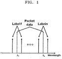
- FIG. 1 is a view explaining the SCM.
- a packet data containing information exists in each wavelength ⁇ n (n is a natural number), and carries a label with a sub-carrier at a position away from each wavelength ⁇ n as much as ⁇ f c and is transmitted together with the label.
- the WDM is a scheme that multiplexes plural optical channels having different wavelengths onto a single optical fiber and transmits the channels.
- a packet data is transmitted with an odd-numbered wavelength ⁇ 2 m +1 (m is a positive integer) and a label is carried with an even-numbered wavelength ⁇ 2 m (m is a positive integer).
- the label is transmitted using an extra wavelength, and thus, an extra optical channel is required to transmit the label.
- the wavelength to transmit the packet data and the wavelength to transmit the label are neighbors to each other, they are not easily divided from each other.
- a label is allocated between a first bit and an eighth bit of a packet data and transmitted.
- the TDM requires a packet data processing to obtain label information, and thus, a label swapping process becomes complicated.
- a method for transmitting an optical packet data and a control data about the optical packet data comprises grouping a plurality of wavelengths into at least two wavelength bandwidths, each wavelength bandwidth being composed of neighboring wavelengths, and transmitting the optical packet data and the control data with wavelengths of different wavelength bandwidths respectively.
- a node which transmits optical data including an optical packet data and control data about the optical packet data.
- the node comprises a packet generator for generating the optical packet data using wavelengths of a first wavelength bandwidth which is composed of neighboring wavelengths, a label generator for generating the control data using wavelengths of a second wavelength bandwidth which is composed of neighboring wavelengths except for the wavelengths of the first wavelength bandwidth, and a coarse wavelength division multiplexer for combining the packet data received from the packet data generator and the control data received from the label generator and outputting the combined data.
- a node which receives optical data including an optical packet data and control data about the optical packet data.
- the node comprises a first coarse wavelength division multiplexer for dividing wavelengths of a first wavelength bandwidth, which is composed of neighboring wavelengths, and wavelengths of a second wavelength bandwidth, a packet data receiver for receiving the optical packet data transmitted with the wavelengths of the first wavelength bandwidth, a label swapping part for receiving and updating the control data which is transmitted with wavelengths of the second wavelength bandwidth, and a second coarse wavelength division multiplexer for combining the packet data received from the packet data receiver and the control data received from the label swapping part into an optical data and the outputting the combined optical data.
- the invention thus provides an apparatus and method for effectively transmitting packet data and labels about the packet data in an optical packet data switching network.
- the apparatus and method are capable of simply embodying a label swapping part for updating received labels.
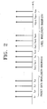
- FIG. 2 illustrates a wavelength bandwidth to transmit packet data and a wavelength bandwidth to transmit a label.
- the label is control data that encompasses path information about packet data.
- the wavelength bandwidth to transmit the packet data is from ⁇ 1 to ⁇ n
- the wavelength bandwidth to transmit the label is from ⁇ n +1 to ⁇ 2 n .
- the wavelength to transmit the packet data and the wavelength to transmit the label about the packet data has a constant wavelength difference ⁇ n from each other. 'n' varies according to a user's setting.
- WDM wavelength division multiplexing
- a wavelength to transmit packet data and a wavelength to transmit a label about the packet data are neighbored to each other.
- the wavelength to transmit the packet data is ⁇ m , then the wavelength to transmit the label about the packet data is ⁇ m +1 .
- the wavelength to transmit the label about the packet data is ⁇ n+m . Accordingly, the wavelength to transmit the packet data and the wavelength to transmit the label can be easily divided from each other.
- wavelengths are grouped into two wavelength bandwidths. However, if there are three types of optical signals transmitted from the node, wavelengths are grouped into three wavelength bandwidths to transmit the three types of optical signals.
- FIG. 3 illustrates a source node in which packet data and a label about the packet data are generated according to an embodiment of the present invention.
- the source node includes a packet data generator 300, a label generator 302 and a coarse wavelength division multiplexer (CWDM) 304.
- CWDM coarse wavelength division multiplexer
- FIG. 3 illustrates only the necessary elements for the sake of brevity.
- the data packet generator 300 generates packet data to be transmitted to a destination node. Since a process of generating the packet data has less relation to the present invention, its detailed description is omitted.
- the packet data generator 300 transmits the generated packet data with a wavelength of ⁇ 1 .
- ⁇ 1 an optical channel for transmitting the packet data
- the packet data generator 300 transmits the packet data to the CWDM 304 with ⁇ 1 .
- the label generator 302 generates path information about the packet data generated by the packet generator 300.
- the path information includes an address of the source node, an address of the destination node and an address of a relay node which are to receive the packet data.
- the label generator 302 transmits the generated label with a wavelength of ⁇ n +1 .
- an optical channel for transmitting the label is identical to ⁇ n +1 .
- the label generator 302 transmits the label to the CWDM 304 with ⁇ n +1 .
- the CWDM 304 combines the packet data received from the packet data generator 300 and the label received from the label generator 302 and outputs the resultant data. That is, the CWDM 304 combines the packet data of the wavelength of ⁇ 1 and the label of the wavelength of ⁇ n +1 and outputs the resultant data through a single optical fiber.
- the source node transmits the label and then transmits the packet data.
- the relay node can previously set up an optical path based on the received label to transmit the packet data.
- FIG. 4 illustrates a relay node which receives packet data and a label according to an embodiment of the present invention.
- the relay node includes two CWDM 400 and 420, a packet data receiver 410, a label receiver 412, and a label swapping part 414.
- other elements can be included in the relay node, but only the necessary elements are described here for the sake of brevity.
- the source node and the relay node are different from each other in this description, they actually comprise the same elements.
- a node performs different operations according to whether the node serves as a source node or a relay node. That is, the source node as shown in FIG. 3 actually comprises a packet data receiver and a label receiver, but the packet data receiver and the label receiver are omitted from this description in order to highlight the function of transmitting the packet data and the label. Therefore, if the source node serves as a relay node, it performs corresponding operations through the packet data receiver and the label receiver.
- the CWDM 400 receives the packet data and the label using an optical path from a neighboring source node or relay node.
- the packet data is received with ⁇ 1
- the label is received with ⁇ n +1 .
- the CWDM 400 divides the packet data and the label according to the wavelengths.
- a wavelength division multiplexer includes a CWDM and a dense WDM (DWDM).
- the DWDM divides wavelengths (channels) such that divided wavelengths have a narrow gap thereamong.
- Channels divided by the DWDM have a channel gap of 1.6nm (200 Ghz), 0.8nm (100 Ghz) or 0.4nm (50Ghz).
- the CWDM divides wavelengths such that divided wavelengths have a broad gap thereamong.
- channels divided by the CWDM have a channel gap above 20nm. Therefore, if the packet data and the label received through the optical path have a narrow wavelength gap, the DWDM easily divides the packet data and the label from each other, but the CWDM cannot do so.
- the packet data is transmitted with ⁇ 1 and the label is transmitted with ⁇ n +1 , and thus, the CWDM 400 easily divides the packet data and the label.
- the packet data divided by the CWDM 400 is transmitted to the packet data receiver 410, whereas the divided label is transmitted to the label receiver 412.
- the packet data receiver 410 Because the packet data receiver 410 is not the destination node of the packet data, it forwards the packet data to the CWDM 420. If the packet data receiver 410 is the destination node of the packet data, the packet data receiver 410 forwards the packet data to an upper layer thereof. The packet data receiver 410 determines whether it is the destination node of the received packet data based on the received label.
- the label receiver 412 receives the label from the CWDM 400 and analyzes information included in the label.
- the information includes a source node address and a destination node address of packet data which is to be received or has been already received.
- the label receiver 412 analyzes the information of the destination node address included in the label, and it determines whether it is a destination node of packet data subsequently received. Because the description of FIG. 4 is about the relay node, the relay node determines that it is not the destination node of the packet data. Accordingly, the label receiver 412 forwards the label to the label swapping part 414.
- the label swapping part 414 updates the label received from the label receiver 412. That is, the label swapping part 414 adds its own information to the received label, thereby updating path information.
- FIG. 4 illustrates the label swapping part 414 and FIG. 3 illustrates the label generator 302.
- the label swapping part 414 and the label generator 302 may be integrated into a single structure. That is, the label swapping part 414 performs not only the label updating operation but also the label generation operation, or the label generator 302 performs not only the label generation operation but also the label updating operation.
- the label swapping part 414 updates the label and then transmits the same to the CWDM 420.
- the CWDM 420 combines the packet data received from the packet data receiver 410 and the label received from the label swapping part 414 and outputs the resultant data.
- the operation performed by the CWDM 420 is identical to that of the CWDM 304 of FIG. 3.
- a node serves as a source node and a relay node. If the node is a destination node, it is operated in the same manner as the relay node. However, the relay node forwards the packet data and label to a neighboring node, whereas the destination node forwards the packet data to an upper layer thereof.
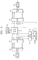
- FIG. 5 illustrates a node according to an embodiment of the present invention.
- the node comprises two cyclic array wavelength gratings (cyclic AWGs) 502 and 516, two CWDMs 504 and 514, a packet data generator 506, an optical switch 508, a label receiver 510, and a label swapping part 512.
- the node receives a packet data and a label which are amplified by an optical amplifier 500 and forwards the packet data and the label which are processed by the respective elements to another optical amplifier 518.
- the optical amplifiers 500 and 518 are located in an optical path.
- the optical amplifier 500 amplifies the packet data and the label and forwards the same to the cyclic AWG 502.
- the cyclic AWG 502 groups wavelengths of the received packet data and label and outputs the group of wavelengths. For example, if the number of wavelengths inputted into the cyclic AWG 502 is 2n, the cyclic AWG 502 groups the wavelengths into n number of groups, i.e., from a first group to an n-th group.
- the cyclic AWG 502 outputs each group of wavelengths through a single path.
- the first group includes the wavelengths ⁇ 1 , ⁇ n +1 and the second group includes the wavelengths ⁇ 2 , ⁇ n +2 .
- the n-th group includes the wavelengths ⁇ n , ⁇ 2 n .
- Each group consists of at least two wavelengths and is referred to as a wavelength group hereinafter.
- Each wavelength group is composed of a wavelength to transmit a packet data and a wavelength to transmit a label about the packet data.
- the cyclic AWG 502 groups the wavelengths into the wavelength groups and forwards the groups of wavelengths to the CWDM 504.
- the CWDM 504 un-groups the groups of wavelengths into individual wavelengths. For example, if the CWDM 504 receives the first group of wavelengths, the first group is divided into the wavelengths ⁇ 1 , ⁇ n +1 respectively. If the CWDM 504 receives the n-th group of wavelengths, the n-th group is divided into the wavelength ⁇ n , ⁇ 2 n respectively.
- the CWDM 504 forwards the wavelengths that belong to a packet data wavelength bandwidth to the optical switch 508, and forwards the wavelengths that belong to a label wavelength bandwidth to the label receiver 510.
- the packet data wavelength bandwidth and the label wavelength bandwidth were described in the above with reference to FIG. 2.
- the packet data generator 506 generates a packet data and transmits the same to a destination node.
- the packet data generator 506 performs its function when the node serves as a source node. Referring to FIG. 5, the packet data generated by the packet data generator 506 is transmitted with ⁇ a . 'a' ranges from 1 to n.
- a label about the packet data has to be generated, which was described in the above.
- the optical switch 508 determines whether the node is the destination node of the packet data received from the CWDM 504 based on the received label.
- the optical switch 508 extracts the packet data the destination node of which is the node. As shown in FIG. 5, the optical switch 508 extracts the packet data having the wavelength of ⁇ b , 'b' ranges from 1 to n. Albeit not shown in FIG. 5, the optical switch 508 may include a packet data receiver or may perform a packet data receiving function.
- the label receiver 510 detects whether there is a label among the received labels that indicates that the node is the destination node. If there is a label indicating that the node is the destination node, the label is extracted because the label does not need to be transmitted. Referring to FIG. 5, the label having the wavelength of ⁇ n+b is extracted. The label receiver 510 transmits the received labels to the label swapping part 512.
- the label swapping part 512 updates the labels received from the label receiver 510.
- the label swapping part 512 adds the information about the node to path information, thereby updating the label.
- the label swapping part 512 generates a label indicating the path information about the packet data if the node generates the packet data. For example, if the packet data generator 506 generates a packet data having a wavelength of ⁇ a , the label swapping part 512 generates a label of a wavelength of ⁇ n+a .
- the label swapping part 512 transmits the updated or generated labels to the CWDM 514.
- the CWDM 514 groups the packet data received from the optical switch 508 and the labels received from the label swapping part 512 into groups, respectively, and outputs the groups of packet data and labels.
- the groups were described in the above. That is, the CWDM 514 performs a reverse operation to that performed by the CWDM 504.
- the cyclic AWG 516 also performs a reverse operation to that performed by the cyclic AWG 502.
- the present invention provides an apparatus and method for dividing the wavelength bandwidth to transmit the packet data and the wavelength bandwidth to transmit the label. Accordingly, the wavelength to transmit the packet data and the wavelength to transmit the label can be easily divided by the CWDM.
Landscapes
- Engineering & Computer Science (AREA)
- Computer Networks & Wireless Communication (AREA)
- Physics & Mathematics (AREA)
- Electromagnetism (AREA)
- Signal Processing (AREA)
- Computing Systems (AREA)
- Optical Communication System (AREA)
- Data Exchanges In Wide-Area Networks (AREA)
Abstract
Description
- The present invention relates to an optical packet data switching network. More particularly, the present invention relates to an apparatus and method for transmitting packet data and labels without error in an optical packet data switching network.
- A general optical packet data switching network is composed of a source node where a sender is located, a relay node where a sender and a receiver are located, and a destination node where a receiver is located. Optical signals generated at the source node are transmitted to the destination node through the relay node or directly transmitted to the destination node.
- In the optical packet data switching network, a label, which indicates information about a packet data and a moving direction of the packet data, is transmitted. The label is generated at the source node and transmitted to the relay node, and the relay node updates the received label using a label swapping part. The relay node determines which node is the destination node of the received packet data based on the received label and transmits the packet data to the determined destination node. A label swapping refers to a process that updates information of the received label about the moving direction of the packet data. The label swapping part updates the information about the moving direction by adding its own information to the received label.
- The label is transmitted according to various schemes, for example, a time division multiplexing (TDM), a wavelength division multiplexing (WDM), an optical code division multiplexing (OCDM), a sub-carrier multiplexing (SCM), and an orthogonal optical label.
- FIG. 1 is a view explaining the SCM. According to the SCM of FIG. 1, a packet data containing information exists in each wavelength λ n (n is a natural number), and carries a label with a sub-carrier at a position away from each wavelength λ n as much as ±f c and is transmitted together with the label.
- The WDM is a scheme that multiplexes plural optical channels having different wavelengths onto a single optical fiber and transmits the channels. According to the WDM, a packet data is transmitted with an odd-numbered wavelength λ 2m+1 (m is a positive integer) and a label is carried with an even-numbered wavelength λ 2m (m is a positive integer). As described above, according to the WDM, the label is transmitted using an extra wavelength, and thus, an extra optical channel is required to transmit the label. Also, according to the WDM, since the wavelength to transmit the packet data and the wavelength to transmit the label are neighbors to each other, they are not easily divided from each other.
- According to the TDM, a label is allocated between a first bit and an eighth bit of a packet data and transmitted. Unlike the WDM and SCM, the TDM requires a packet data processing to obtain label information, and thus, a label swapping process becomes complicated.
- According to a first aspect of the invention, there is provided a method for transmitting an optical packet data and a control data about the optical packet data. The method comprises grouping a plurality of wavelengths into at least two wavelength bandwidths, each wavelength bandwidth being composed of neighboring wavelengths, and transmitting the optical packet data and the control data with wavelengths of different wavelength bandwidths respectively.
- According to a second aspect of the invention, there is provided a node which transmits optical data including an optical packet data and control data about the optical packet data. The node comprises a packet generator for generating the optical packet data using wavelengths of a first wavelength bandwidth which is composed of neighboring wavelengths, a label generator for generating the control data using wavelengths of a second wavelength bandwidth which is composed of neighboring wavelengths except for the wavelengths of the first wavelength bandwidth, and a coarse wavelength division multiplexer for combining the packet data received from the packet data generator and the control data received from the label generator and outputting the combined data.
- According to a third aspect of the invention, there is provided a node which receives optical data including an optical packet data and control data about the optical packet data. The node comprises a first coarse wavelength division multiplexer for dividing wavelengths of a first wavelength bandwidth, which is composed of neighboring wavelengths, and wavelengths of a second wavelength bandwidth, a packet data receiver for receiving the optical packet data transmitted with the wavelengths of the first wavelength bandwidth, a label swapping part for receiving and updating the control data which is transmitted with wavelengths of the second wavelength bandwidth, and a second coarse wavelength division multiplexer for combining the packet data received from the packet data receiver and the control data received from the label swapping part into an optical data and the outputting the combined optical data.
- The invention thus provides an apparatus and method for effectively transmitting packet data and labels about the packet data in an optical packet data switching network. The apparatus and method are capable of simply embodying a label swapping part for updating received labels.
- The above aspects and other advantages of the present invention become apparent by describing an embodiment of the present invention in greater detail with reference to the accompanying drawings, in which:
- FIG. 1 is a view showing a label which is transmitted in an optical packet data switching network according to the sub-carrier multiplexing (SCM);
- FIG. 2 is a view showing a packet data wavelength bandwidth to transmit a packet data and a label wavelength bandwidth to transmit a label according to an embodiment of the present invention;
- FIG. 3 is a view showing a source node in which a packet data and a label are generated according to an embodiment of the present invention;
- FIG. 4 is a view showing a relay node and a destination node in which a packet data and a label are processed according to an embodiment of the present invention; and
- FIG. 5 is a view showing a node according to an embodiment of the present invention.
- Hereinafter, an apparatus and method for effectively transmitting a packet data and a label in an optical packet switching network according to an embodiment of the present invention will now be described in detail.
- FIG. 2 illustrates a wavelength bandwidth to transmit packet data and a wavelength bandwidth to transmit a label. The label is control data that encompasses path information about packet data. Referring to FIG. 2, the wavelength bandwidth to transmit the packet data is from λ1 to λ n , whereas the wavelength bandwidth to transmit the label is from λ n+1 to λ2n . The wavelength to transmit the packet data and the wavelength to transmit the label about the packet data has a constant wavelength difference λ n from each other. 'n' varies according to a user's setting. According to a conventional wavelength division multiplexing (WDM), a wavelength to transmit packet data and a wavelength to transmit a label about the packet data are neighbored to each other. If the wavelength to transmit the packet data is λ m , then the wavelength to transmit the label about the packet data is λ m+1. However, according to the present invention, if the wavelength to transmit the packet data is λ m , the wavelength to transmit the label about the packet data is λ n+m . Accordingly, the wavelength to transmit the packet data and the wavelength to transmit the label can be easily divided from each other. According to the embodiment explained in FIG. 2, since an optical signal transmitted from a node is the packet data and the label about the packet data, wavelengths are grouped into two wavelength bandwidths. However, if there are three types of optical signals transmitted from the node, wavelengths are grouped into three wavelength bandwidths to transmit the three types of optical signals.
- FIG. 3 illustrates a source node in which packet data and a label about the packet data are generated according to an embodiment of the present invention. Referring to FIG. 3, the source node includes a
packet data generator 300, alabel generator 302 and a coarse wavelength division multiplexer (CWDM) 304. In addition to the above elements, other elements can be included in the source node. FIG. 3 illustrates only the necessary elements for the sake of brevity. - The
data packet generator 300 generates packet data to be transmitted to a destination node. Since a process of generating the packet data has less relation to the present invention, its detailed description is omitted. Thepacket data generator 300 transmits the generated packet data with a wavelength of λ1. Hereinafter, it is assumed that an optical channel for transmitting the packet data is identical to λ1. Thepacket data generator 300 transmits the packet data to theCWDM 304 with λ1. - The
label generator 302 generates path information about the packet data generated by thepacket generator 300. The path information includes an address of the source node, an address of the destination node and an address of a relay node which are to receive the packet data. Thelabel generator 302 transmits the generated label with a wavelength of λ n+1. Hereinafter, it is assumed that an optical channel for transmitting the label is identical to λ n+1. Thelabel generator 302 transmits the label to theCWDM 304 with λ n+1. - The CWDM 304 combines the packet data received from the
packet data generator 300 and the label received from thelabel generator 302 and outputs the resultant data. That is, theCWDM 304 combines the packet data of the wavelength of λ1 and the label of the wavelength of λ n+1 and outputs the resultant data through a single optical fiber. Of course, the source node transmits the label and then transmits the packet data. To this end, the relay node can previously set up an optical path based on the received label to transmit the packet data. - FIG. 4 illustrates a relay node which receives packet data and a label according to an embodiment of the present invention. The relay node includes two
CWDM packet data receiver 410, alabel receiver 412, and alabel swapping part 414. In addition to the above elements, other elements can be included in the relay node, but only the necessary elements are described here for the sake of brevity. - Although the source node and the relay node are different from each other in this description, they actually comprise the same elements. A node performs different operations according to whether the node serves as a source node or a relay node. That is, the source node as shown in FIG. 3 actually comprises a packet data receiver and a label receiver, but the packet data receiver and the label receiver are omitted from this description in order to highlight the function of transmitting the packet data and the label. Therefore, if the source node serves as a relay node, it performs corresponding operations through the packet data receiver and the label receiver.
- The
CWDM 400 receives the packet data and the label using an optical path from a neighboring source node or relay node. The packet data is received with λ1, whereas the label is received with λ n+1. TheCWDM 400 divides the packet data and the label according to the wavelengths. - In general, a wavelength division multiplexer (WDM) includes a CWDM and a dense WDM (DWDM). The DWDM divides wavelengths (channels) such that divided wavelengths have a narrow gap thereamong. Channels divided by the DWDM have a channel gap of 1.6nm (200 Ghz), 0.8nm (100 Ghz) or 0.4nm (50Ghz). Compared to the DWDM, the CWDM divides wavelengths such that divided wavelengths have a broad gap thereamong. Generally, channels divided by the CWDM have a channel gap above 20nm. Therefore, if the packet data and the label received through the optical path have a narrow wavelength gap, the DWDM easily divides the packet data and the label from each other, but the CWDM cannot do so.
- However, according to the present invention, the packet data is transmitted with λ1 and the label is transmitted with λ n+1, and thus, the
CWDM 400 easily divides the packet data and the label. The packet data divided by theCWDM 400 is transmitted to thepacket data receiver 410, whereas the divided label is transmitted to thelabel receiver 412. - Because the
packet data receiver 410 is not the destination node of the packet data, it forwards the packet data to theCWDM 420. If thepacket data receiver 410 is the destination node of the packet data, thepacket data receiver 410 forwards the packet data to an upper layer thereof. Thepacket data receiver 410 determines whether it is the destination node of the received packet data based on the received label. - The
label receiver 412 receives the label from theCWDM 400 and analyzes information included in the label. The information includes a source node address and a destination node address of packet data which is to be received or has been already received. Thelabel receiver 412 analyzes the information of the destination node address included in the label, and it determines whether it is a destination node of packet data subsequently received. Because the description of FIG. 4 is about the relay node, the relay node determines that it is not the destination node of the packet data. Accordingly, thelabel receiver 412 forwards the label to thelabel swapping part 414. - The
label swapping part 414 updates the label received from thelabel receiver 412. That is, thelabel swapping part 414 adds its own information to the received label, thereby updating path information. FIG. 4 illustrates thelabel swapping part 414 and FIG. 3 illustrates thelabel generator 302. However, thelabel swapping part 414 and thelabel generator 302 may be integrated into a single structure. That is, thelabel swapping part 414 performs not only the label updating operation but also the label generation operation, or thelabel generator 302 performs not only the label generation operation but also the label updating operation. - The
label swapping part 414 updates the label and then transmits the same to theCWDM 420. TheCWDM 420 combines the packet data received from thepacket data receiver 410 and the label received from thelabel swapping part 414 and outputs the resultant data. The operation performed by theCWDM 420 is identical to that of theCWDM 304 of FIG. 3. - The description above concerns a case in which a node serves as a source node and a relay node. If the node is a destination node, it is operated in the same manner as the relay node. However, the relay node forwards the packet data and label to a neighboring node, whereas the destination node forwards the packet data to an upper layer thereof.
- FIG. 5 illustrates a node according to an embodiment of the present invention. Hereinafter, a node according to an embodiment of the present invention will now be described in detail with reference to FIG. 5. The node comprises two cyclic array wavelength gratings (cyclic AWGs) 502 and 516, two
CWDMs packet data generator 506, anoptical switch 508, alabel receiver 510, and alabel swapping part 512. The node receives a packet data and a label which are amplified by anoptical amplifier 500 and forwards the packet data and the label which are processed by the respective elements to anotheroptical amplifier 518. In general, theoptical amplifiers - The
optical amplifier 500 amplifies the packet data and the label and forwards the same to thecyclic AWG 502. Thecyclic AWG 502 groups wavelengths of the received packet data and label and outputs the group of wavelengths. For example, if the number of wavelengths inputted into thecyclic AWG 502 is 2n, thecyclic AWG 502 groups the wavelengths into n number of groups, i.e., from a first group to an n-th group. Thecyclic AWG 502 outputs each group of wavelengths through a single path. Hereinafter, the wavelengths are described in detail. The first group includes the wavelengths λ1 , λ n+1 and the second group includes the wavelengths λ2 , λ n+2 . The n-th group includes the wavelengths λ n , λ2n . Each group consists of at least two wavelengths and is referred to as a wavelength group hereinafter. Each wavelength group is composed of a wavelength to transmit a packet data and a wavelength to transmit a label about the packet data. - The
cyclic AWG 502 groups the wavelengths into the wavelength groups and forwards the groups of wavelengths to theCWDM 504. TheCWDM 504 un-groups the groups of wavelengths into individual wavelengths. For example, if theCWDM 504 receives the first group of wavelengths, the first group is divided into the wavelengths λ1, λ n+1 respectively. If theCWDM 504 receives the n-th group of wavelengths, the n-th group is divided into the wavelength λ n , λ2n respectively. TheCWDM 504 forwards the wavelengths that belong to a packet data wavelength bandwidth to theoptical switch 508, and forwards the wavelengths that belong to a label wavelength bandwidth to thelabel receiver 510. The packet data wavelength bandwidth and the label wavelength bandwidth were described in the above with reference to FIG. 2. - The
packet data generator 506 generates a packet data and transmits the same to a destination node. Thepacket data generator 506 performs its function when the node serves as a source node. Referring to FIG. 5, the packet data generated by thepacket data generator 506 is transmitted with λ a . 'a' ranges from 1 to n. When thepacket data generator 506 generates the packet data, a label about the packet data has to be generated, which was described in the above. - The
optical switch 508 determines whether the node is the destination node of the packet data received from theCWDM 504 based on the received label. Theoptical switch 508 extracts the packet data the destination node of which is the node. As shown in FIG. 5, theoptical switch 508 extracts the packet data having the wavelength of λ b , 'b' ranges from 1 to n. Albeit not shown in FIG. 5, theoptical switch 508 may include a packet data receiver or may perform a packet data receiving function. - The
label receiver 510 detects whether there is a label among the received labels that indicates that the node is the destination node. If there is a label indicating that the node is the destination node, the label is extracted because the label does not need to be transmitted. Referring to FIG. 5, the label having the wavelength of λ n+b is extracted. Thelabel receiver 510 transmits the received labels to thelabel swapping part 512. - The
label swapping part 512 updates the labels received from thelabel receiver 510. Thelabel swapping part 512 adds the information about the node to path information, thereby updating the label. Thelabel swapping part 512 generates a label indicating the path information about the packet data if the node generates the packet data. For example, if thepacket data generator 506 generates a packet data having a wavelength of λ a , thelabel swapping part 512 generates a label of a wavelength of λ n+a . Thelabel swapping part 512 transmits the updated or generated labels to theCWDM 514. - The
CWDM 514 groups the packet data received from theoptical switch 508 and the labels received from thelabel swapping part 512 into groups, respectively, and outputs the groups of packet data and labels. The groups were described in the above. That is, theCWDM 514 performs a reverse operation to that performed by theCWDM 504. Thecyclic AWG 516 also performs a reverse operation to that performed by thecyclic AWG 502. - As described above, the present invention provides an apparatus and method for dividing the wavelength bandwidth to transmit the packet data and the wavelength bandwidth to transmit the label. Accordingly, the wavelength to transmit the packet data and the wavelength to transmit the label can be easily divided by the CWDM.
- The foregoing embodiment and advantages are merely exemplary and are not to be construed as limiting the present invention. The present teaching can be readily applied to other types of apparatus. Also, the description of the embodiments of the present invention is intended to be illustrative, and not to limit the scope of the claims, and many alternatives, modifications, and variations will be apparent to those skilled in the art.
Claims (12)
- A method for transmitting optical packet data and control data about the optical packet data, the method comprising:grouping a plurality of wavelengths into at least two wavelength bandwidths, each wavelength bandwidth being composed of neighboring wavelengths; andtransmitting the optical packet data and the control data with wavelengths of different wavelength bandwidths respectively.
- The method as claimed in claim 1, wherein, if the plurality of wavelengths are from λ1 to λ2n (n is a predetermined natural number), a wavelength bandwidth to transmit the packet data is from λ1 to λ n and a wavelength bandwidth to transmit the control data is from λ n+1 to λ2n .
- The method as claimed in claim 2, wherein the wavelength to transmit the packet data and the wavelength to transmit the control data has a difference of λ n from each other.
- The method as claimed in claim 3, further comprising extracting two pieces of optical data having the difference from the optical data transmitted from an optical path, and dividing the two pieces of optical data.
- A node for transmitting optical data including optical packet data and control data about the optical packet data, the node comprising:a packet generator configured to generate the optical packet data using wavelengths of a first wavelength bandwidth which is composed of neighboring wavelengths;a label generator configured to generate the control data using wavelengths of a second wavelength bandwidth which is composed of neighboring wavelengths except for the wavelengths of the first wavelength bandwidth; anda coarse wavelength division multiplexer for combining the packet data received from the packet data generator and the control data received from the label generator and outputting the combined data.
- The node as claimed in claim 5, wherein the first wavelength bandwidth is from λ1 to λ n (n is a predetermined natural number) and the second wavelength bandwidth is from λ n+1 to λ2n .
- The node as claimed claim 6, wherein the wavelength to transmit the packet data and the wavelength to transmit the control data has a difference of λ n from each other.
- A node for receiving optical data including optical packet data and control data about the optical packet data, the node comprising:a first coarse wavelength division multiplexer configured to divide wavelengths of a first wavelength bandwidth, which is composed of neighboring wavelengths, and wavelengths of a second wavelength bandwidth;a packet data receiver configured to receive the optical packet data transmitted with the wavelengths of the first wavelength bandwidth;a label swapping part configured to receive and update the control data which is transmitted with wavelengths of the second wavelength bandwidth; anda second coarse wavelength division multiplexer configured to combine the packet data received from the packet data receiver and the control data received from the label swapping part into combined optical data and output the combined optical data.
- The node as claimed in claim 8, wherein the first wavelength bandwidth is from λ1 to λ n (n is a predetermined natural number) and the second wavelength bandwidth from λ n+1 to λ2n .
- The node as claimed in claim 9, wherein the wavelength to transmit the packet data and the wavelength to transmit the control data has a difference of λ n from each other.
- The node as claimed in claim 10, further comprising a first cyclic array wavelength grating configured to extract two pieces of optical data having the difference from the optical data transmitted from an optical path and transmitting the two pieces of optical data to the first coarse wavelength division multiplexer.
- The node as claimed in claim 11, further comprising a second cyclic array wavelength grating configured to combine the at least two pieces of optical data transmitted from the second coarse wavelength division multiplexer and outputting the combined optical data.
Applications Claiming Priority (1)
| Application Number | Priority Date | Filing Date | Title |
|---|---|---|---|
| KR1020040088650A KR100661348B1 (en) | 2004-11-03 | 2004-11-03 | Apparatus and Method for Label Transmission in Optical Packet Data Switching Network |
Publications (2)
| Publication Number | Publication Date |
|---|---|
| EP1655989A2 true EP1655989A2 (en) | 2006-05-10 |
| EP1655989A3 EP1655989A3 (en) | 2010-05-05 |
Family
ID=35798515
Family Applications (1)
| Application Number | Title | Priority Date | Filing Date |
|---|---|---|---|
| EP05256678A Withdrawn EP1655989A3 (en) | 2004-11-03 | 2005-10-27 | Apparatus and method for label transmission in optical packet data switching network |
Country Status (4)
| Country | Link |
|---|---|
| US (1) | US7769293B2 (en) |
| EP (1) | EP1655989A3 (en) |
| JP (1) | JP2006135988A (en) |
| KR (1) | KR100661348B1 (en) |
Cited By (1)
| Publication number | Priority date | Publication date | Assignee | Title |
|---|---|---|---|---|
| RU2496268C2 (en) * | 2009-06-18 | 2013-10-20 | Квэлкомм Инкорпорейтед | Power scaling for multi-carrier high-speed uplink packet access |
Families Citing this family (7)
| Publication number | Priority date | Publication date | Assignee | Title |
|---|---|---|---|---|
| KR100842278B1 (en) | 2006-12-08 | 2008-06-30 | 한국전자통신연구원 | Optical label exchange and optical payload reproducing apparatus and method, optical switching apparatus using the apparatus |
| US20080253768A1 (en) * | 2007-04-12 | 2008-10-16 | Nec Laboratories America, Inc. | High Bit Rate Packet Generation with High Spectral Efficiency in an Optical Network |
| JP5303248B2 (en) * | 2008-11-20 | 2013-10-02 | Kddi株式会社 | Optical burst signal accommodation optical insertion / separation device and optical burst signal accommodation optical insertion / separation method |
| WO2014183127A2 (en) * | 2013-05-10 | 2014-11-13 | Huawei Technologies Co., Ltd. | System and method for photonic switching |
| US9537598B2 (en) * | 2014-04-11 | 2017-01-03 | Nec Corporation | Architecture of open-flow based software-defined optical label swapping |
| US9712899B2 (en) * | 2014-12-11 | 2017-07-18 | Alcatel Lucent | Hybrid optical switch for software-defined networking |
| US12375838B2 (en) * | 2020-10-30 | 2025-07-29 | Nippon Telegraph And Telephone Corporation | Optical communication apparatus, optical communication system and optical communication method |
Citations (1)
| Publication number | Priority date | Publication date | Assignee | Title |
|---|---|---|---|---|
| WO1993021706A1 (en) | 1992-04-09 | 1993-10-28 | British Telecommunications Public Limited Company | Optical processing system |
Family Cites Families (10)
| Publication number | Priority date | Publication date | Assignee | Title |
|---|---|---|---|---|
| US5680490A (en) | 1995-09-08 | 1997-10-21 | Lucent Technologies Inc. | Comb splitting system and method for a multichannel optical fiber communication network |
| JP3614320B2 (en) | 1999-08-06 | 2005-01-26 | 日本電信電話株式会社 | Wavelength multiple polymerization demultiplexing transmission system and wavelength division multiplexing transmission apparatus |
| JP2001111488A (en) | 1999-10-01 | 2001-04-20 | Nippon Telegr & Teleph Corp <Ntt> | WDM signal demultiplexer |
| JP3472809B2 (en) * | 2000-09-06 | 2003-12-02 | 独立行政法人通信総合研究所 | Optical packet routing method and device using multi-wavelength label, and optical packet network using multi-wavelength label |
| JP2002116341A (en) | 2000-10-05 | 2002-04-19 | Sun Tec Kk | Wavelength multiplexer / demultiplexer |
| US6768827B2 (en) * | 2002-01-16 | 2004-07-27 | The Regents Of The University Of California | Integrated optical router |
| KR100474694B1 (en) | 2002-10-12 | 2005-03-10 | 삼성전자주식회사 | Optical ring network for burst data communication |
| KR100459572B1 (en) | 2002-10-15 | 2004-12-03 | 삼성전자주식회사 | Optical multi-ring network for burst data communication |
| US7389048B2 (en) * | 2003-06-18 | 2008-06-17 | Nippon Telegraph And Telephone Corporation | Optical wavelength-division multiple access system and optical network unit |
| US7359635B2 (en) * | 2004-05-03 | 2008-04-15 | Avago Technologies Fiber Ip Pte Ltd | Optically-controlled optical network and switching node therefor |
-
2004
- 2004-11-03 KR KR1020040088650A patent/KR100661348B1/en not_active Expired - Fee Related
-
2005
- 2005-10-27 EP EP05256678A patent/EP1655989A3/en not_active Withdrawn
- 2005-11-03 US US11/265,164 patent/US7769293B2/en not_active Expired - Fee Related
- 2005-11-04 JP JP2005320955A patent/JP2006135988A/en active Pending
Patent Citations (1)
| Publication number | Priority date | Publication date | Assignee | Title |
|---|---|---|---|---|
| WO1993021706A1 (en) | 1992-04-09 | 1993-10-28 | British Telecommunications Public Limited Company | Optical processing system |
Non-Patent Citations (1)
| Title |
|---|
| "Cutting-Edge Technologies on Broadband and Scalable Photonic-Network-Packet switched networks based on all-optical label processing", OPTICAL REVIEW, SPRINGER BERLIN, DE, vol. 11, no. 2, 1 March 2004 (2004-03-01), pages 106 - 112 |
Cited By (2)
| Publication number | Priority date | Publication date | Assignee | Title |
|---|---|---|---|---|
| RU2496268C2 (en) * | 2009-06-18 | 2013-10-20 | Квэлкомм Инкорпорейтед | Power scaling for multi-carrier high-speed uplink packet access |
| US9674800B2 (en) | 2009-06-18 | 2017-06-06 | Qualcomm Incorporated | Power scaling for multi-carrier high-speed uplink packet access |
Also Published As
| Publication number | Publication date |
|---|---|
| KR100661348B1 (en) | 2006-12-27 |
| EP1655989A3 (en) | 2010-05-05 |
| US7769293B2 (en) | 2010-08-03 |
| US20060093355A1 (en) | 2006-05-04 |
| JP2006135988A (en) | 2006-05-25 |
| KR20060039536A (en) | 2006-05-09 |
Similar Documents
| Publication | Publication Date | Title |
|---|---|---|
| EP1628423B1 (en) | Optical wavelength multiplex access system | |
| CN104919736B (en) | Photon interconnection with restructural drop and insert feature | |
| US20200274633A1 (en) | Transmitting device and transmission system | |
| CN102986154A (en) | Using Multiple Shared Wavelength Lockers to Stabilize Transponders in Wavelength Division Multiplexing (WDM) Networks | |
| US6452703B1 (en) | Optical add-drop multiplexing technique and wavelength division multiplexing optical link using such a multiplexing technique | |
| JP2010074565A (en) | Optical add-drop multiplexing apparatus | |
| CN100499435C (en) | Optical multiring net for burst data communication | |
| US20060228114A1 (en) | Wavelength-selective routing using an optical add/drop architecture | |
| US7769293B2 (en) | Apparatus and method for label transmission in optical packet data switching network | |
| US20090060504A1 (en) | Apparatus and method for protection switching of optical channel | |
| EP1445976B1 (en) | Wavelength path monitoring/correcting apparatus in transparent optical cross-connect and method thereof | |
| KR20040056470A (en) | optical communication node system, electric/optical routing system, optical packet routing method and optical packet routing network system using the node and routing system | |
| JP3335081B2 (en) | Node device used in network system performing packet communication, network system using the same, and communication method used there | |
| EP0758173B1 (en) | Node device, network system and method for performing packet communication | |
| EP3661083A1 (en) | Light wavelength separation device and light wavelength separation method | |
| US20030206743A1 (en) | Cross connecting device and optical communication system | |
| US7277639B2 (en) | Bi-directional optical add/drop multiplexer for WDM optical networks | |
| JPWO2018179686A1 (en) | Optical signal demultiplexing device, optical signal receiving device, optical signal transmitting and receiving device, and optical signal demultiplexing method | |
| US7310481B2 (en) | WDM-PON having bus structure | |
| JP2012039659A (en) | Optical add-drop multiplexing apparatus | |
| EP1653766B1 (en) | Optical packet communication system using wavelength-offset polarization-division multiplexing labeling | |
| US20050129403A1 (en) | Method and system for communicating optical traffic at a node | |
| JP5437344B2 (en) | Optical add / drop multiplexer | |
| JP2004180293A (en) | Wavelength conversion device and optical line distribution device using the same | |
| JP5427870B2 (en) | Optical add / drop multiplexer |
Legal Events
| Date | Code | Title | Description |
|---|---|---|---|
| PUAI | Public reference made under article 153(3) epc to a published international application that has entered the european phase |
Free format text: ORIGINAL CODE: 0009012 |
|
| AK | Designated contracting states |
Kind code of ref document: A2 Designated state(s): AT BE BG CH CY CZ DE DK EE ES FI FR GB GR HU IE IS IT LI LT LU LV MC NL PL PT RO SE SI SK TR |
|
| AX | Request for extension of the european patent |
Extension state: AL BA HR MK YU |
|
| RAP1 | Party data changed (applicant data changed or rights of an application transferred) |
Owner name: SAMSUNG ELECTRONICS CO., LTD. |
|
| PUAL | Search report despatched |
Free format text: ORIGINAL CODE: 0009013 |
|
| AK | Designated contracting states |
Kind code of ref document: A3 Designated state(s): AT BE BG CH CY CZ DE DK EE ES FI FR GB GR HU IE IS IT LI LT LU LV MC NL PL PT RO SE SI SK TR |
|
| AX | Request for extension of the european patent |
Extension state: AL BA HR MK YU |
|
| 17P | Request for examination filed |
Effective date: 20101105 |
|
| AKX | Designation fees paid |
Designated state(s): DE FR GB |
|
| 17Q | First examination report despatched |
Effective date: 20101222 |
|
| RAP1 | Party data changed (applicant data changed or rights of an application transferred) |
Owner name: SAMSUNG ELECTRONICS CO., LTD. |
|
| GRAP | Despatch of communication of intention to grant a patent |
Free format text: ORIGINAL CODE: EPIDOSNIGR1 |
|
| INTG | Intention to grant announced |
Effective date: 20131219 |
|
| RIN1 | Information on inventor provided before grant (corrected) |
Inventor name: KIM, HYUN-CHIN, 112-2004 SAMSUNG APARTMENT Inventor name: YOUN, CHUN-JU Inventor name: PARK, KEUN-JOO, A-317 DORMITORY OF SAMSUNG ADV. Inventor name: SEO, YOUNG-KWANG Inventor name: RHEE, JUNE-KOO, 405-2002 WOOSUNG 4DANJI APT. |
|
| STAA | Information on the status of an ep patent application or granted ep patent |
Free format text: STATUS: THE APPLICATION IS DEEMED TO BE WITHDRAWN |
|
| 18D | Application deemed to be withdrawn |
Effective date: 20140430 |