EP1655612A1 - Universal test fixture - Google Patents
Universal test fixture Download PDFInfo
- Publication number
- EP1655612A1 EP1655612A1 EP05008790A EP05008790A EP1655612A1 EP 1655612 A1 EP1655612 A1 EP 1655612A1 EP 05008790 A EP05008790 A EP 05008790A EP 05008790 A EP05008790 A EP 05008790A EP 1655612 A1 EP1655612 A1 EP 1655612A1
- Authority
- EP
- European Patent Office
- Prior art keywords
- contact points
- target
- universal fixture
- switch
- universal
- Prior art date
- Legal status (The legal status is an assumption and is not a legal conclusion. Google has not performed a legal analysis and makes no representation as to the accuracy of the status listed.)
- Withdrawn
Links
Images


Classifications
-
- G—PHYSICS
- G01—MEASURING; TESTING
- G01R—MEASURING ELECTRIC VARIABLES; MEASURING MAGNETIC VARIABLES
- G01R1/00—Details of instruments or arrangements of the types included in groups G01R5/00 - G01R13/00 and G01R31/00
- G01R1/02—General constructional details
- G01R1/06—Measuring leads; Measuring probes
- G01R1/067—Measuring probes
- G01R1/073—Multiple probes
- G01R1/07307—Multiple probes with individual probe elements, e.g. needles, cantilever beams or bump contacts, fixed in relation to each other, e.g. bed of nails fixture or probe card
- G01R1/07364—Multiple probes with individual probe elements, e.g. needles, cantilever beams or bump contacts, fixed in relation to each other, e.g. bed of nails fixture or probe card with provisions for altering position, number or connection of probe tips; Adapting to differences in pitch
- G01R1/07385—Multiple probes with individual probe elements, e.g. needles, cantilever beams or bump contacts, fixed in relation to each other, e.g. bed of nails fixture or probe card with provisions for altering position, number or connection of probe tips; Adapting to differences in pitch using switching of signals between probe tips and test bed, i.e. the standard contact matrix which in its turn connects to the tester
-
- G—PHYSICS
- G01—MEASURING; TESTING
- G01R—MEASURING ELECTRIC VARIABLES; MEASURING MAGNETIC VARIABLES
- G01R1/00—Details of instruments or arrangements of the types included in groups G01R5/00 - G01R13/00 and G01R31/00
- G01R1/02—General constructional details
- G01R1/06—Measuring leads; Measuring probes
- G01R1/067—Measuring probes
- G01R1/073—Multiple probes
- G01R1/07307—Multiple probes with individual probe elements, e.g. needles, cantilever beams or bump contacts, fixed in relation to each other, e.g. bed of nails fixture or probe card
- G01R1/07314—Multiple probes with individual probe elements, e.g. needles, cantilever beams or bump contacts, fixed in relation to each other, e.g. bed of nails fixture or probe card the body of the probe being perpendicular to test object, e.g. bed of nails or probe with bump contacts on a rigid support
- G01R1/07328—Multiple probes with individual probe elements, e.g. needles, cantilever beams or bump contacts, fixed in relation to each other, e.g. bed of nails fixture or probe card the body of the probe being perpendicular to test object, e.g. bed of nails or probe with bump contacts on a rigid support for testing printed circuit boards
- G01R1/07335—Multiple probes with individual probe elements, e.g. needles, cantilever beams or bump contacts, fixed in relation to each other, e.g. bed of nails fixture or probe card the body of the probe being perpendicular to test object, e.g. bed of nails or probe with bump contacts on a rigid support for testing printed circuit boards for double-sided contacting or for testing boards with surface-mounted devices (SMD's)
Definitions
- testpads, vias, traces and plated through-holes on the bare PCB are tested for electrical connectivity and continuity.
- Typical measurements conducted by bare-board testers include shorts, opens and impedance or resistance.
- Most conventional bare-board testers fall into one of two categories, either a "bed of nails” tester or a “flying probe” tester.
- a "bed of nails” tester is used on low resolution PCBs that have line and space widths of 250 ⁇ m or greater.
- the "bed of nails” tester utilizes a bare-board fixture containing a series of plastic sheets with holes drilled to permit passage of pins (nails).
- the PCB is placed in direct contact with the bare-board fixture.
- the pins on the fixture connect the various targets (e.g., testpads, vias, traces and through-holes) on the PCB to the internal electronics of the tester.
- targets e.g., testpads, vias, traces and through-holes
- the density of pins in the test fixtures has increased.
- the design and fabrication of the test fixtures has become more complicated. Since the pins must match points on a predefined grid in the tester and also connect with points on the PCB that are not necessarily aligned with the tester grid, some of the pins must be routed through the plastic sheets at angles. As a result, the cost of producing the test fixtures has significantly increased.
- a “flying probe” tester is a universal tester that does not require a fixture.
- the "flying probe” tester uses a small number of probes that are sequentially positioned over numerous test points on the PCB. Although the "flying probe” tester permits testing of high resolution PCBs, the serial approach of testing targets on a PCB reduces the throughput of the tester. Thus, the "flying probe” tester is significantly slower than the "bed of nails” tester.
- a universal fixture for testing an electronic device such as a bare printed circuit board (PCB)
- PCB bare printed circuit board
- the universal fixture includes a plurality of addressable contact points.
- Each of the contact points includes a switch connected to a conductor capable of creating an electrical connection to the device.
- two of the contact points on the universal fixture are selected based on the position of the target on the device relative to the contact points.
- Embodiments in accordance with the invention provide a universal fixture, testing system and a method for testing electronic devices, such as bare printed circuit boards (PCBs).
- the universal fixture is capable of testing PCBs at rates of speed greater than those achievable by traditional "flying probe” testers.
- FIG. 1 is a top perspective view of a testing assembly including universal fixtures for testing an electronic device according to an exemplary embodiment in accordance with the invention.
- the testing assembly is generally designated by reference number 10 and includes first universal fixture 30 and second universal fixture 40.
- An electronic device 20, such as a bare PCB, is sandwiched between first universal fixture 30 and second universal fixture 40.
- First universal fixture 30 is placed in direct contact with one side of PCB 20, while second universal fixture 40 is placed in direct contact with the other side of PCB 20.
- Each universal fixture 30 and 40 includes a plurality of randomly addressable contact points 50 arranged on a two-dimensional grid pattern for creating electrical connections to targets on PCB 20.
- targets can include testpads, vias, traces and through-holes on PCB 20.
- Contact points 50 are illustrated schematically in FIG. 1 as arranged in an orthogonal array of uniformly spaced-apart rows and columns of contact points 50.
- Contact points 50 include conductors or metal wires that protrude outward from the substrate containing the array towards electronic device 20.
- the density of contact points 50 is selected to ensure that each target on PCB 20 is capable of being contacted by at least two contact points 50 on one of first universal fixture 30 or second universal fixture 40.
- the center-to-center spacing between contact points 50 on each universal fixture 30 and 40 is less than or equal to 10 ⁇ m pitch.
- test equipment can include any electronic equipment needed to run or monitor the test, such as a computer and peripherals, a digital voltmeter, a current source, a digital logic analyzer, oscilloscopes, a network analyzer, cameras, pneumatic controls or other such test equipment.
- FIG. 2 is a schematic that illustrates one configuration of contact points of a universal fixture according to an exemplary embodiment in accordance with the invention.
- Contact points 200a and 200b represent selected contact points in a universal fixture for testing target 250.
- Contact points 200a and 200b can be implemented in universal fixture 30 or 40 in FIG. 1 as contact points 50.
- Contact point 200a includes switch 210 and conductor 240.
- Switch 210 is connected to conductor 240, which is in contact with test point 245 on target 250.
- Contact point 200b includes switch 215 and conductor 260.
- Switch 215 is connected to conductor 260, which is in contact with test point 265 on target 250.
- Conductors 240 and 260 are pins, metal wires or probes configured to create an electrical connection to target 250.
- switches 210 and 215 are thin film transistors.
- Contact points 200a and 200b are selected by gate selector 230 and data selector 220.
- the gates of switches 210 and 215 are connected to gate selector 230 while the sources of switches 210 and 215 are connected to data selector 220.
- Gate selector 230 and data selector 220 each include additional switches (not shown) for connecting contact points 200a and 200b to external test electronics.
- gate selector 230 controls the gates of switches 210 and 215 to turn on or turn off switches 210 and 215.
- Data selector 220 can connect contact points 200a and 200b to a current source in order to source a known current through target 250, and to a voltmeter to measure the voltage across target 250 when gate selector 230 places switches 210 and 215 in a first or "on" state.
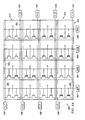
- FIG. 3 is a schematic that illustrates a universal fixture 300 including an array 310 of contact points 200 configured as shown in FIG. 2.
- Universal fixture 300 can be implemented into test assembly 10 in FIG. 1 as universal fixture 30 or 40.
- Contact points 200 within array 310 are arranged in rows 320 and columns 330. Each row 320 is connected to gate selector 230 via lines 325. Each column 330 is connected to data selector 220 via lines 335.
- gate selector 230 transmits an electronic signal on line 325 connected to contact point 200 and data selector 220 transmits an electronic signal on line 335 connected to contact point 200.
- gate selector 230 and data selector 220 select two contact points 200a and 200b to conduct a measurement of a target 250 on a device under test, such as a bare PCB.
- a typical measurement for a bare PCB is to measure the resistance of a trace (target 250) on the bare PCB to determine the electrical connectivity of the trace.
- FIG. 4A is a schematic that illustrates a two-point measurement circuit, similar to the measurement circuit shown in FIG. 2, that can be used to measure the resistance of a trace on a PCB.
- a current source I sources and flows a known current Iforce through the unknown resistance Rdut of the DUT.
- the voltage Vsense that develops across the DUT resistance Rdut is measured by a voltmeter V, and the DUT resistance Rdut is determined by dividing the measured voltage Vsense by the sourced current Iforce.
- the voltage is measured not only across the DUT resistance Rdut, but also across the contact resistance R1 and R2.
- switch 210 and conductor 240 add resistance R1
- switch 215 and conductor 260 add resistance R2.
- the resistance R1 and R2 of the switches 210 and 215 and conductors 240 and 260 is large in comparison to the DUT (e.g., trace) resistance Rdut, it is difficult to obtain an accurate measurement of Rdut using the two-point measurement circuit shown in FIG. 4A.
- a four-point measurement circuit can be used.
- the current source I and voltmeter V are both separately connected to the DUT resistance Rdut.
- the known current Iforce is sourced through the DUT resistance Rdut, as in FIG. 4A.
- the voltage drop across the DUT resistance Rdut is measured after the contact resistance R3 and R4.
- the high impedance of the digital voltmeter minimizes the current flow through the voltmeter.
- the DUT resistance Rdut is equal to the ratio of the voltage registering on the digital voltmeter Vsense to the known current Iforce.
- FIG. 5 is a schematic that illustrates another configuration of contact points in a universal fixture according to another exemplary embodiment in accordance with the invention.
- the contact point configuration shown in FIG. 5 uses a four-point measurement circuit similar to the circuit shown in FIG. 4B.
- Contact points 500a and 500b represent selected contact points in a universal fixture for testing target 550.
- Contact points 500a and 500b can be implemented in universal fixture 30 or 40 in FIG. 1 as contact points 50.
- Contact point 500a includes switch 505, switch 515 and conductor 518. Switches 505 and 515 are each separately connected to conductor 518, which is in contact with test point 545 on target 550.
- Contact point 500b includes switch 510, switch 520 and conductor 522. Switches 510 and 520 are each separately connected to conductor 522, which is in contact with test point 555 on target 550.
- Conductors 518 and 522 are pins, metal wires or probes configured to create an electrical connection to target 550.
- switches 505, 510, 515 and 520 are thin film transistors.
- Contact points 500a and 500b are selected by force selector 540, sense selector 530 and gate selector 560 that are configured to place switches 505, 510, 515 and 520 in a first or "on" state.
- the gates of switches 505, 510, 515 and 520 are connected to gate selector 560, the sources of switches 505 and 510 are connected to force selector 540 and the drains of switches 515 and 520 are connected to sense selector 530.
- the drains of switches 505 and 510 are connected to conductors 518 and 522, respectively, while the sources of switches 515 and 520 are connected to conductors 518 and 522, respectively.
- Force selector 540, sense selector 530 and gate selector 560 each include additional switches (not shown) for connecting contact points 500a and 500b to external test electronics.
- force selector 540 can connect contact points 500a and 500b to a current source via switches 505 and 510 to source a known current through target 550 and sense selector 530 can connect contact points 500a and 500b to a voltmeter via switches 515 and 520 to measure the voltage across target 550.
- the direction of current through target 550 is determined by the connections F+/F- established by force selector 540 to the current source.
- the connections S+/S- to the voltmeter to properly measure the voltage drop across target 550 are determined by sense selector 530.
- FIG. 6A is a schematic that illustrates a universal fixture 600 including an array 610 of contact points 500 configured as shown in FIG. 5.
- Universal fixture 600 can be implemented into test assembly 10 in FIG. 1 as universal fixture 30 or 40.
- Contact points 600 within array 610 are arranged in rows 620 and columns 630. Each row 620 is connected to force selector 540 via lines 640 and sense selector 530 via lines 650. Each column 630 is connected to gate selector 560 via lines 660.
- force selector 540 transmits an electronic signal on line 640 connected to contact point 500
- sense selector 530 transmits an electronic signal on line 650 connected to contact point 500
- gate selector 560 transmits an electronic signal on line 660 connected to contact point 500.
- FIG. 6B is a schematic that illustrates the universal fixture of FIG. 6A configured to test a target on an electronic device, such as a bare PCB.
- Target 550 is connected between contact points 500a and 500b.
- force selector 540 transmits an electronic signal on line 640a to connect contact point 500a to terminal F+ of an external current source via switch 505
- sense selector 530 transmits an electronic signal on line 650a to connect contact point 500a to terminal S+ of an external voltmeter via switch 515
- gate selector 560 transmits an electronic signal on line 660a connected to contact point 500a to place switches 505 and 510 in a first state to complete the connection to the current source and voltmeter.
- force selector 540 transmits an electronic signal on line 640b to connect contact point 500b to terminal F- of an external current source via switch 510
- sense selector 530 transmits an electronic signal on line 650b to connect contact point 500b to terminal S- of an external voltmeter via switch 520
- gate selector 560 transmits an electronic signal on line 660b connected to contact point 500a to place switches 510 and 520 in a first state to complete the connection to the current source and voltmeter.
- a known current is sourced through target 550 via switches 505 and 510 and conductors 518 and 522.
- the voltage drop across target 550 is measured via switches 515 and 520 and conductors 518 and 522.
- the high impedance of the digital voltmeter minimizes the current flow through the voltmeter.
- the resistance of target 550 is equal to the ratio of the measured voltage to the known current.
- the PCB/DUT permits testing of targets (e.g., traces or features) that have test points on opposite sides of the PCB/DUT
- targets e.g., traces or features
- two universal fixtures are used, and the PCB/DUT is "sandwiched" between the two universal fixtures, as shown in FIG. 1.
- FIG. 7 is a block diagram that illustrates a testing system implementing universal fixtures in accordance with embodiments in accordance with the invention.
- Testing system is designated by reference number 700, and includes processor 710 operable to execute software 720 for testing an electronic device.
- Processor 710 can be any type of microprocessor, microcontroller, programmable logic device, digital signal processor or other processing device.
- Processor 710 is coupled to memory unit 730 and input/output (I/O) unit 740.
- I/O unit 740 can be wired or wireless.
- Display 750 is optionally coupled to testing system 700 and operable to display testing results to an operator of testing system 700.
- processor 710 is operable to execute software 720 to configure universal fixtures 30 and 40 to test a particular electronic device, such as a bare PCB.
- Processor 710 is capable of taking as input data representing test point locations corresponding to a target on the PCB and mapping the test point locations to a stored representation of contact point locations to determine the contact points on universal fixtures 30 and 40 that are nearest aligned to the test point locations.
- Processor 710 is further capable of identifying multiple targets to be tested simultaneously by mapping a pattern of test point locations to different, nearest aligned contact points on universal fixtures 30 and 40.
- To map a pattern of test point locations onto the array of contact points the state (on or off) of each individual contact point within the array is selected depending on the mapping. For example, an "on" state can be selected for a contact point that has more than 1 ⁇ 2 of the contact point area covered by a test point in the pattern. Otherwise, an "off" state can be selected for the contact point.
- Test information indicating selected contact points for testing one or more targets at each time interval is stored by processor 710 in memory unit 730.
- Processor 710 communicates with memory unit 730 and I/O unit 740 to transmit test signals 760 containing the test information for each time interval to test electronics 780.
- Test electronics 780 include contact point selectors, such as selectors 220 and 230 in FIG. 2 or selectors 530, 540 and 560 in FIG. 5, along with any other test equipment, such as a current source, voltmeter or other such test equipment.
- Test electronics 780 selects contact points on universal fixtures 30 and 40 for testing targets on the PCB based on test signals 760 received from processor 710. Measurements 770 obtained by test electronics 780 are transmitted to processor 710 via I/O unit 740 for subsequent processing and/or display on display 750.
- FIG. 8 is a flow chart that illustrates a method, generally designated by reference number 800, for testing an electronic device according to a further exemplary embodiment in accordance with the invention.
- a universal fixture with an array of randomly addressable contact points in accordance with embodiments in accordance with the invention, is provided, as shown in step 801.
- the universal fixture is placed in contact with an electronic device, such as a bare PCB, to test the PCB, as shown in step 802.
- steps 803 and 804 test points corresponding to targets on the PCB are determined, and the test points are mapped to contact points on the universal fixture.
- first and second contact points on the universal fixture that correspond to test points of a particular target on the PCB are selected to obtain a measurement of the target between the first and second selected contact points. If there are additional targets on the PCB to be tested, as shown in step 808, contact points on the universal fixture associated with the additional targets are selected to obtain measurements for the additional targets, as shown in steps 805-807. Otherwise, the process ends at step 809.
Abstract
Description
- Before a printed circuit board (PCB) is loaded with components, the testpads, vias, traces and plated through-holes on the bare PCB are tested for electrical connectivity and continuity. Typical measurements conducted by bare-board testers include shorts, opens and impedance or resistance. Most conventional bare-board testers fall into one of two categories, either a "bed of nails" tester or a "flying probe" tester.
- A "bed of nails" tester is used on low resolution PCBs that have line and space widths of 250 µm or greater. The "bed of nails" tester utilizes a bare-board fixture containing a series of plastic sheets with holes drilled to permit passage of pins (nails). During testing, the PCB is placed in direct contact with the bare-board fixture. The pins on the fixture connect the various targets (e.g., testpads, vias, traces and through-holes) on the PCB to the internal electronics of the tester. Although, the "bed of nails" tester permits nearly simultaneous testing of all targets on a PCB, each unique PCB that is tested requires a different custom fixture.
- As component sizes have shrunk, the density of pins in the test fixtures has increased. In addition, with decreasing component size, the design and fabrication of the test fixtures has become more complicated. Since the pins must match points on a predefined grid in the tester and also connect with points on the PCB that are not necessarily aligned with the tester grid, some of the pins must be routed through the plastic sheets at angles. As a result, the cost of producing the test fixtures has significantly increased.
- A "flying probe" tester is a universal tester that does not require a fixture. The "flying probe" tester uses a small number of probes that are sequentially positioned over numerous test points on the PCB. Although the "flying probe" tester permits testing of high resolution PCBs, the serial approach of testing targets on a PCB reduces the throughput of the tester. Thus, the "flying probe" tester is significantly slower than the "bed of nails" tester.
- In accordance with the invention, a universal fixture for testing an electronic device, such as a bare printed circuit board (PCB), is provided that is capable of testing PCBs at a high rate of speed. The universal fixture includes a plurality of addressable contact points. Each of the contact points includes a switch connected to a conductor capable of creating an electrical connection to the device. To obtain a measurement of a target on the device, two of the contact points on the universal fixture are selected based on the position of the target on the device relative to the contact points.
- Furthermore, the invention provides embodiments with other features and advantages in addition to or in lieu of those discussed above. Many of these features and advantages are apparent from the description below with reference to the following drawings.
- FIG. 1 is a top perspective view of a testing assembly including universal fixtures for testing an electronic device according to an exemplary embodiment in accordance with the invention;
- FIG. 2 is a schematic that illustrates one configuration of contact points of a universal fixture according to an exemplary embodiment in accordance with the invention;
- FIG. 3 is a schematic that illustrates a universal fixture including an array of contact points configured as shown in FIG. 2;
- FIG. 4A is a schematic that illustrates a two-point measurement circuit;
- FIG. 4B is a schematic that illustrates a four-point measurement circuit;
- FIG. 5 is a schematic that illustrates another configuration of contact points a universal fixture according to another exemplary embodiment in accordance with the invention;
- FIG. 6A is a schematic that illustrates a universal fixture including an array of contact points configured as shown in FIG. 5;
- FIG. 6B is a schematic that illustrates the universal fixture of FIG. 6A configured to test a target on an electronic device;
- FIG. 7 is a block diagram that illustrates a testing system implementing universal fixtures in accordance with embodiments in accordance with the invention; and
- FIG. 8 is a flow chart that illustrates a method for testing an electronic device according to a further exemplary embodiment in accordance with the invention.
- Embodiments in accordance with the invention provide a universal fixture, testing system and a method for testing electronic devices, such as bare printed circuit boards (PCBs). The universal fixture is capable of testing PCBs at rates of speed greater than those achievable by traditional "flying probe" testers.
- FIG. 1 is a top perspective view of a testing assembly including universal fixtures for testing an electronic device according to an exemplary embodiment in accordance with the invention. The testing assembly is generally designated by
reference number 10 and includes firstuniversal fixture 30 and seconduniversal fixture 40. Anelectronic device 20, such as a bare PCB, is sandwiched between firstuniversal fixture 30 and seconduniversal fixture 40. Firstuniversal fixture 30 is placed in direct contact with one side ofPCB 20, while seconduniversal fixture 40 is placed in direct contact with the other side ofPCB 20. - Each
universal fixture addressable contact points 50 arranged on a two-dimensional grid pattern for creating electrical connections to targets onPCB 20. For example, targets can include testpads, vias, traces and through-holes onPCB 20.Contact points 50 are illustrated schematically in FIG. 1 as arranged in an orthogonal array of uniformly spaced-apart rows and columns ofcontact points 50.Contact points 50 include conductors or metal wires that protrude outward from the substrate containing the array towardselectronic device 20. The density ofcontact points 50 is selected to ensure that each target onPCB 20 is capable of being contacted by at least twocontact points 50 on one of firstuniversal fixture 30 or seconduniversal fixture 40. For example, in one embodiment, the center-to-center spacing betweencontact points 50 on eachuniversal fixture - When first
universal fixture 30 and seconduniversal fixture 40 are in direct contact withPCB 20, each target on PCB 20 is tested by selecting twocontact points 50 that are best aligned with test points on the target. An electrical signal is applied to the test points fromselected contact points 50 to connect the target onPCB 20 to test equipment (not shown) external to testingassembly 10 in order to test the electrical connection state of the target onPCB 20. For example, test equipment can include any electronic equipment needed to run or monitor the test, such as a computer and peripherals, a digital voltmeter, a current source, a digital logic analyzer, oscilloscopes, a network analyzer, cameras, pneumatic controls or other such test equipment. - FIG. 2 is a schematic that illustrates one configuration of contact points of a universal fixture according to an exemplary embodiment in accordance with the invention.
Contact points testing target 250.Contact points universal fixture contact points 50.Contact point 200a includesswitch 210 andconductor 240. Switch 210 is connected toconductor 240, which is in contact withtest point 245 ontarget 250.Contact point 200b includesswitch 215 andconductor 260.Switch 215 is connected toconductor 260, which is in contact withtest point 265 ontarget 250.Conductors switches - Contact points 200a and 200b are selected by
gate selector 230 anddata selector 220. The gates ofswitches gate selector 230 while the sources ofswitches data selector 220.Gate selector 230 anddata selector 220 each include additional switches (not shown) for connectingcontact points gate selector 230 controls the gates ofswitches switches Data selector 220 can connectcontact points target 250, and to a voltmeter to measure the voltage acrosstarget 250 whengate selector 230 places switches 210 and 215 in a first or "on" state. - FIG. 3 is a schematic that illustrates a
universal fixture 300 including anarray 310 ofcontact points 200 configured as shown in FIG. 2.Universal fixture 300 can be implemented intotest assembly 10 in FIG. 1 asuniversal fixture array 310 are arranged inrows 320 andcolumns 330. Eachrow 320 is connected togate selector 230 vialines 325. Eachcolumn 330 is connected todata selector 220 vialines 335. To selectcontact point 200,gate selector 230 transmits an electronic signal online 325 connected to contactpoint 200 anddata selector 220 transmits an electronic signal online 335 connected to contactpoint 200. - Referring again to FIG. 2,
gate selector 230 anddata selector 220 select twocontact points target 250 on a device under test, such as a bare PCB. A typical measurement for a bare PCB is to measure the resistance of a trace (target 250) on the bare PCB to determine the electrical connectivity of the trace. - FIG. 4A is a schematic that illustrates a two-point measurement circuit, similar to the measurement circuit shown in FIG. 2, that can be used to measure the resistance of a trace on a PCB. As shown in FIG. 4A, in order to measure the resistance of a DUT Rdut, a current source I sources and flows a known current Iforce through the unknown resistance Rdut of the DUT. The voltage Vsense that develops across the DUT resistance Rdut is measured by a voltmeter V, and the DUT resistance Rdut is determined by dividing the measured voltage Vsense by the sourced current Iforce.
- However, as shown in FIG. 4A, the voltage is measured not only across the DUT resistance Rdut, but also across the contact resistance R1 and R2. For example, using the example shown in FIG. 2,
switch 210 andconductor 240 add resistance R1, whileswitch 215 andconductor 260 add resistance R2. When the resistance R1 and R2 of theswitches conductors - Therefore, as shown in FIG. 4B, to improve the accuracy of the Rdut measurement, a four-point measurement circuit can be used. In FIG. 4B, the current source I and voltmeter V are both separately connected to the DUT resistance Rdut. Thus, the known current Iforce is sourced through the DUT resistance Rdut, as in FIG. 4A. However, the voltage drop across the DUT resistance Rdut is measured after the contact resistance R3 and R4. The high impedance of the digital voltmeter minimizes the current flow through the voltmeter. Thus, since there is no voltage drop across the contact resistance R5 and R6, only the DUT resistance Rdut is measured. As a result, the DUT resistance Rdut is equal to the ratio of the voltage registering on the digital voltmeter Vsense to the known current Iforce.
- FIG. 5 is a schematic that illustrates another configuration of contact points in a universal fixture according to another exemplary embodiment in accordance with the invention. The contact point configuration shown in FIG. 5 uses a four-point measurement circuit similar to the circuit shown in FIG. 4B. Contact points 500a and 500b represent selected contact points in a universal fixture for
testing target 550. Contact points 500a and 500b can be implemented inuniversal fixture -
Contact point 500a includesswitch 505,switch 515 andconductor 518.Switches conductor 518, which is in contact withtest point 545 ontarget 550.Contact point 500b includesswitch 510,switch 520 andconductor 522.Switches conductor 522, which is in contact withtest point 555 ontarget 550.Conductors - Contact points 500a and 500b are selected by
force selector 540,sense selector 530 andgate selector 560 that are configured to placeswitches switches gate selector 560, the sources ofswitches selector 540 and the drains ofswitches selector 530. The drains ofswitches conductors switches conductors -
Force selector 540,sense selector 530 andgate selector 560 each include additional switches (not shown) for connectingcontact points force selector 540 can connectcontact points switches target 550 andsense selector 530 can connectcontact points switches target 550. The direction of current throughtarget 550 is determined by the connections F+/F- established byforce selector 540 to the current source. Similarly, the connections S+/S- to the voltmeter to properly measure the voltage drop acrosstarget 550 are determined bysense selector 530. - FIG. 6A is a schematic that illustrates a universal fixture 600 including an
array 610 ofcontact points 500 configured as shown in FIG. 5. Universal fixture 600 can be implemented intotest assembly 10 in FIG. 1 asuniversal fixture array 610 are arranged inrows 620 andcolumns 630. Eachrow 620 is connected to forceselector 540 vialines 640 andsense selector 530 vialines 650. Eachcolumn 630 is connected togate selector 560 vialines 660. To selectcontact point 500,force selector 540 transmits an electronic signal online 640 connected to contactpoint 500,sense selector 530 transmits an electronic signal online 650 connected to contactpoint 500 andgate selector 560 transmits an electronic signal online 660 connected to contactpoint 500. - FIG. 6B is a schematic that illustrates the universal fixture of FIG. 6A configured to test a target on an electronic device, such as a bare PCB.
Target 550 is connected betweencontact points contact point 500a,force selector 540 transmits an electronic signal online 640a to connectcontact point 500a to terminal F+ of an external current source viaswitch 505,sense selector 530 transmits an electronic signal online 650a to connectcontact point 500a to terminal S+ of an external voltmeter viaswitch 515 andgate selector 560 transmits an electronic signal online 660a connected to contactpoint 500a to placeswitches contact point 500b,force selector 540 transmits an electronic signal online 640b to connectcontact point 500b to terminal F- of an external current source viaswitch 510,sense selector 530 transmits an electronic signal online 650b to connectcontact point 500b to terminal S- of an external voltmeter viaswitch 520 andgate selector 560 transmits an electronic signal online 660b connected to contactpoint 500a to placeswitches - A known current is sourced through
target 550 viaswitches conductors target 550 is measured viaswitches conductors switches target 550 is measured. As a result, the resistance oftarget 550 is equal to the ratio of the measured voltage to the known current. It should be noted that the connections to thetarget 550 shown in FIG. 6B apply to embodiments where both test points are on the same side of the PCB/DUT. However, in embodiments where the PCB/DUT permits testing of targets (e.g., traces or features) that have test points on opposite sides of the PCB/DUT, two universal fixtures are used, and the PCB/DUT is "sandwiched" between the two universal fixtures, as shown in FIG. 1. - FIG. 7 is a block diagram that illustrates a testing system implementing universal fixtures in accordance with embodiments in accordance with the invention. Testing system is designated by
reference number 700, and includesprocessor 710 operable to executesoftware 720 for testing an electronic device.Processor 710 can be any type of microprocessor, microcontroller, programmable logic device, digital signal processor or other processing device.Processor 710 is coupled tomemory unit 730 and input/output (I/O)unit 740. I/O unit 740 can be wired or wireless.Display 750 is optionally coupled totesting system 700 and operable to display testing results to an operator oftesting system 700. - In one embodiment in accordance with the invention,
processor 710 is operable to executesoftware 720 to configureuniversal fixtures Processor 710 is capable of taking as input data representing test point locations corresponding to a target on the PCB and mapping the test point locations to a stored representation of contact point locations to determine the contact points onuniversal fixtures Processor 710 is further capable of identifying multiple targets to be tested simultaneously by mapping a pattern of test point locations to different, nearest aligned contact points onuniversal fixtures - Test information indicating selected contact points for testing one or more targets at each time interval is stored by
processor 710 inmemory unit 730.Processor 710 communicates withmemory unit 730 and I/O unit 740 to transmittest signals 760 containing the test information for each time interval to testelectronics 780.Test electronics 780 include contact point selectors, such asselectors selectors Test electronics 780 selects contact points onuniversal fixtures test signals 760 received fromprocessor 710.Measurements 770 obtained bytest electronics 780 are transmitted toprocessor 710 via I/O unit 740 for subsequent processing and/or display ondisplay 750. - FIG. 8 is a flow chart that illustrates a method, generally designated by
reference number 800, for testing an electronic device according to a further exemplary embodiment in accordance with the invention. Initially, a universal fixture with an array of randomly addressable contact points, in accordance with embodiments in accordance with the invention, is provided, as shown instep 801. The universal fixture is placed in contact with an electronic device, such as a bare PCB, to test the PCB, as shown instep 802. Insteps - Thereafter, as shown in steps 805-807, first and second contact points on the universal fixture that correspond to test points of a particular target on the PCB are selected to obtain a measurement of the target between the first and second selected contact points. If there are additional targets on the PCB to be tested, as shown in
step 808, contact points on the universal fixture associated with the additional targets are selected to obtain measurements for the additional targets, as shown in steps 805-807. Otherwise, the process ends atstep 809. - The innovative concepts described in the present application can be modified and varied over a wide rage of applications. Accordingly, the scope of patented subject matter should not be limited to any of the specific exemplary teachings discussed, but is instead defined by the following claims.
Claims (10)
- A universal fixture (30) for testing an electronic device (20), comprising:a plurality of addressable contact points (200), each of said contact points (200) including a switch (210) connected to a conductor (240) capable of creating an electrical connection to said device (20);wherein two of said contact points (200a and 200b) are selected contact points for obtaining a measurement of a target (250) on said device (20);wherein the selection of said selected contact points (200a and 200b) is configurable based on a position of said target (250) on said device (20) relative to said contact points (200).
- The universal fixture (30) according to Claim 1, wherein said plurality of addressable contact points (200) are arranged in an array (310) having rows (320) and columns (330), and the spacing between adjacent ones of said conductors (240) is smaller than the spacing between adjacent targets (250) on said device (20).
- The universal fixture (30) according to Claim 1, wherein a current is sourced through said target (250) and a voltage is measured across said target (250) when each said switch (210 and 215) in each of said selected contact points (200a and 200b) is in a first state.
- The universal fixture (30) according to Claim 1, wherein said universal fixture includes a first universal fixture (30) and a second universal fixture (40), said device (20) being sandwiched between said first universal fixture (30) and said second universal fixture (40).
- The universal fixture (30) according to Claim 1, wherein said device (20) is a bare printed circuit board.
- The universal fixture (30) according to Claim 1, wherein said switch (210) includes at least one thin film transistor.
- The universal fixture (30) according to Claim 1, wherein each said switch of said selected contact points (500a and 500b) includes a first switch (505 and 510) for sourcing a current through said target (550) when said first switch (505 and 510) is in a first state and a second switch (515 and 520) for measuring a voltage across said target (550) when said second switch (515 and 520) is in said first state.
- A method for testing an electronic device (20), comprising:providing (801) a universal fixture (30) including a plurality of addressable contact points (200), each of said contact points (200) including a switch (210) connected to a conductor (240) capable of creating an electrical connection to said device (20); andselecting (802-807) two of said contact points (200a and 200b) to obtain a measurement of a target (250) on said device (20) based on a position of said target (250) on said device (20) relative to said contact points (200).
- The method according to Claim 8, further comprising:sourcing a current through said target (550) using a first switch (505 and 510) in each of said selected contact points (500a and 500b); andmeasuring a voltage across said target (550) using a second switch (515 and 520) in each of said selected contact points (500a and 500b).
- The method according to Claim 8, wherein said selecting comprises:mapping (804) target locations on said device (20) to contact point locations on said universal fixture (30) to select said selected contact points (200a and 200b).
Applications Claiming Priority (1)
| Application Number | Priority Date | Filing Date | Title |
|---|---|---|---|
| US10/975,140 US7071717B2 (en) | 2004-10-28 | 2004-10-28 | Universal test fixture |
Publications (1)
| Publication Number | Publication Date |
|---|---|
| EP1655612A1 true EP1655612A1 (en) | 2006-05-10 |
Family
ID=34935554
Family Applications (1)
| Application Number | Title | Priority Date | Filing Date |
|---|---|---|---|
| EP05008790A Withdrawn EP1655612A1 (en) | 2004-10-28 | 2005-04-21 | Universal test fixture |
Country Status (3)
| Country | Link |
|---|---|
| US (1) | US7071717B2 (en) |
| EP (1) | EP1655612A1 (en) |
| JP (1) | JP2006126197A (en) |
Families Citing this family (6)
| Publication number | Priority date | Publication date | Assignee | Title |
|---|---|---|---|---|
| US7187165B2 (en) * | 2004-12-10 | 2007-03-06 | Agilent Technologies, Inc. | Method and system for implicitly encoding preferred probing locations in a printed circuit board design for use in tester fixture build |
| CA2592901C (en) * | 2007-07-13 | 2012-03-27 | Martin Blouin | Semi-generic in-circuit test fixture |
| CN101796481B (en) * | 2007-08-31 | 2012-07-04 | 应用材料公司 | Photovoltaic production line |
| JP5503255B2 (en) * | 2009-11-10 | 2014-05-28 | グローバル・オーエルイーディー・テクノロジー・リミテッド・ライアビリティ・カンパニー | Pixel circuit, display device, and inspection method |
| KR102252687B1 (en) | 2014-08-18 | 2021-05-18 | 삼성전자주식회사 | Test system executing short-test of plurality of test units simultaneously and test system executing open-test of plurality of test units simultaneously |
| CN110726669B (en) * | 2019-08-31 | 2022-05-24 | 苏州国科测试科技有限公司 | Flying probe is camera subassembly and flying probe test equipment for test equipment |
Citations (4)
| Publication number | Priority date | Publication date | Assignee | Title |
|---|---|---|---|---|
| US3370232A (en) * | 1965-05-07 | 1968-02-20 | Xebec Corp | Switching apparatus for verifying the resistive integrity of electrical wiring systems |
| US4271516A (en) * | 1978-08-25 | 1981-06-02 | Racal Automation Limited | Automatic testing of electrical circuitry |
| US5781021A (en) * | 1994-01-11 | 1998-07-14 | Key Solutions Ltd. | Universal fixtureless test equipment |
| US6292004B1 (en) * | 1999-04-23 | 2001-09-18 | Douglas Kocher | Universal grid interface |
Family Cites Families (13)
| Publication number | Priority date | Publication date | Assignee | Title |
|---|---|---|---|---|
| JPH0763788A (en) * | 1993-08-21 | 1995-03-10 | Hewlett Packard Co <Hp> | Probe, electrical part / circuit inspecting device and electrical part / method of circuit inspection |
| US5432460A (en) * | 1994-01-03 | 1995-07-11 | International Business Machines Corporation | Apparatus and method for opens and shorts testing of a circuit board |
| US5493230A (en) * | 1994-02-25 | 1996-02-20 | Everett Charles Technologies, Inc. | Retention of test probes in translator fixtures |
| US5570027A (en) * | 1995-04-19 | 1996-10-29 | Photocircuits Corporation | Printed circuit board test apparatus and method |
| US5945836A (en) * | 1996-10-29 | 1999-08-31 | Hewlett-Packard Company | Loaded-board, guided-probe test fixture |
| US6661245B1 (en) * | 1996-10-31 | 2003-12-09 | International Business Machines Corporation | Method to eliminate wiring of electrical fixtures using spring probes |
| US6677776B2 (en) * | 1998-05-11 | 2004-01-13 | Micron Technology, Inc. | Method and system having switching network for testing semiconductor components on a substrate |
| EP1031042B1 (en) * | 1998-11-02 | 2001-06-20 | ATG TEST SYSTEMS GmbH & Co. KG | Device for testing printed boards |
| US6496025B1 (en) * | 1998-12-11 | 2002-12-17 | Gte Communication Systems Corporation | Method and apparatus for testing printed circuit board assemblies |
| US6597190B2 (en) * | 2000-09-29 | 2003-07-22 | Intel Corporation | Method and apparatus for testing electronic devices |
| US6657449B2 (en) * | 2000-12-21 | 2003-12-02 | Hansaem Digitec Co., Ltd. | Test pin unit for PCB test device and feeding device of the same |
| US6667630B2 (en) * | 2001-07-26 | 2003-12-23 | Obaida A. Abdulky | Universal flying probe fixture |
| JP2003240812A (en) * | 2002-02-14 | 2003-08-27 | Taiyo Kogyo Kk | Inspection fixture and inspection method using it |
-
2004
- 2004-10-28 US US10/975,140 patent/US7071717B2/en not_active Expired - Fee Related
-
2005
- 2005-04-21 EP EP05008790A patent/EP1655612A1/en not_active Withdrawn
- 2005-10-27 JP JP2005312766A patent/JP2006126197A/en active Pending
Patent Citations (4)
| Publication number | Priority date | Publication date | Assignee | Title |
|---|---|---|---|---|
| US3370232A (en) * | 1965-05-07 | 1968-02-20 | Xebec Corp | Switching apparatus for verifying the resistive integrity of electrical wiring systems |
| US4271516A (en) * | 1978-08-25 | 1981-06-02 | Racal Automation Limited | Automatic testing of electrical circuitry |
| US5781021A (en) * | 1994-01-11 | 1998-07-14 | Key Solutions Ltd. | Universal fixtureless test equipment |
| US6292004B1 (en) * | 1999-04-23 | 2001-09-18 | Douglas Kocher | Universal grid interface |
Also Published As
| Publication number | Publication date |
|---|---|
| US20060097738A1 (en) | 2006-05-11 |
| US7071717B2 (en) | 2006-07-04 |
| JP2006126197A (en) | 2006-05-18 |
Similar Documents
| Publication | Publication Date | Title |
|---|---|---|
| US3777260A (en) | Grid for making electrical contact | |
| EP1655612A1 (en) | Universal test fixture | |
| CN105865319A (en) | PCB testing method, PCB manufacturing method and PCB | |
| JPH0526985A (en) | Semiconductor integrated circuit measuring | |
| JPS635274A (en) | Method and device for inspecting printed substrate | |
| US7106081B2 (en) | Parallel calibration system for a test device | |
| US7323897B2 (en) | Mock wafer, system calibrated using mock wafer, and method for calibrating automated test equipment | |
| US6894524B1 (en) | Daisy chain gang testing | |
| US6867597B2 (en) | Method and apparatus for finding a fault in a signal path on a printed circuit board | |
| JPH09107011A (en) | Semiconductor device and aligning method thereof | |
| KR100935645B1 (en) | Test array and method for testing memory arrays | |
| CN108693388B (en) | Kelvin connection with positioning accuracy | |
| KR20120005941A (en) | Probe unit for inspection of circuit board and circuit board inspection device | |
| US6894513B2 (en) | Multipoint plane measurement probe and methods of characterization and manufacturing using same | |
| JPH11101841A (en) | Conductive paste through hole type double-sided printed wiring board and its electric characteristics inspection equipment | |
| US4091325A (en) | Verification technique for checking wrapped wire electronic boards | |
| KR100355716B1 (en) | Test method of low resistor for in-circuit tester | |
| TW200846686A (en) | A lead contact module for detecting circuit board | |
| KR20040024352A (en) | PCB Tester | |
| Friedl | Automated low resistance measurement to test the reliability of plated via holes of unpopulated circuit boards | |
| US20020105348A1 (en) | Electronically measuring pin-to-pad alignment using resistive pads | |
| JPH10186006A (en) | Method of testing printed circuit board | |
| JP2705288B2 (en) | Circuit board inspection method, inspection board, and circuit board inspection device | |
| JPS61180153A (en) | Device and method for testing printed circuit board | |
| JP2900649B2 (en) | Sheet for analysis of wiring board and analysis method |
Legal Events
| Date | Code | Title | Description |
|---|---|---|---|
| PUAI | Public reference made under article 153(3) epc to a published international application that has entered the european phase |
Free format text: ORIGINAL CODE: 0009012 |
|
| AK | Designated contracting states |
Kind code of ref document: A1 Designated state(s): AT BE BG CH CY CZ DE DK EE ES FI FR GB GR HU IE IS IT LI LT LU MC NL PL PT RO SE SI SK TR |
|
| AX | Request for extension of the european patent |
Extension state: AL BA HR LV MK YU |
|
| 17P | Request for examination filed |
Effective date: 20060421 |
|
| AKX | Designation fees paid |
Designated state(s): DE FR GB |
|
| RAP1 | Party data changed (applicant data changed or rights of an application transferred) |
Owner name: AGILENT TECHNOLOGIES, INC. |
|
| 17Q | First examination report despatched |
Effective date: 20060613 |
|
| GRAP | Despatch of communication of intention to grant a patent |
Free format text: ORIGINAL CODE: EPIDOSNIGR1 |
|
| STAA | Information on the status of an ep patent application or granted ep patent |
Free format text: STATUS: THE APPLICATION IS DEEMED TO BE WITHDRAWN |
|
| 18D | Application deemed to be withdrawn |
Effective date: 20071221 |