EP1655544A2 - Muffle for a cooking oven - Google Patents
Muffle for a cooking oven Download PDFInfo
- Publication number
- EP1655544A2 EP1655544A2 EP05109367A EP05109367A EP1655544A2 EP 1655544 A2 EP1655544 A2 EP 1655544A2 EP 05109367 A EP05109367 A EP 05109367A EP 05109367 A EP05109367 A EP 05109367A EP 1655544 A2 EP1655544 A2 EP 1655544A2
- Authority
- EP
- European Patent Office
- Prior art keywords
- muffle
- flaps
- parts
- oven
- constituted
- Prior art date
- Legal status (The legal status is an assumption and is not a legal conclusion. Google has not performed a legal analysis and makes no representation as to the accuracy of the status listed.)
- Withdrawn
Links
Images

Classifications
-
- F—MECHANICAL ENGINEERING; LIGHTING; HEATING; WEAPONS; BLASTING
- F24—HEATING; RANGES; VENTILATING
- F24C—DOMESTIC STOVES OR RANGES ; DETAILS OF DOMESTIC STOVES OR RANGES, OF GENERAL APPLICATION
- F24C15/00—Details
- F24C15/08—Foundations or supports plates; Legs or pillars; Casings; Wheels
Definitions
- the present invention relates to an improved muffle for ovens intended to cook particularly food and the like.
- the invention also relates to a cooking oven particularly for food and the like.
- the term "muffle” is used to designate the internal chamber of an oven for food and the like that is suitable to accommodate for example the dishes to be heated or cooked.
- Muffles constituted by two substantially C-shaped parts, the respective concavities of which face each other so as to form a cooking compartment, are currently known and widespread.
- Such cooking compartment is closed at the rear by a back and at the front by the door for inserting/removing the items that are to be cooked or have been cooked.
- the two C-shaped parts are connected to each other and to the back by means of corresponding flaps, which are coupled by way of connecting means.
- Such connecting means are generally constituted by a continuous braze welding of the overlapping flaps, so that said flaps are sealed and ensure good tightness with respect to the hot air that circulates inside the muffle.
- connection can be provided by spot welding and by subsequent internal enameling at the lines of contact between the welded flaps.
- the aim of the present invention is to provide an improved muffle that can be assembled easily and more rapidly and cheaply than known types of muffle.
- an object of the present invention is to provide an improved muffle in which the heat retention characteristics are not lower than in known muffles.
- Another obj ect of the present invention is to provide a muffle that can be installed easily even in known and already commercially available types of oven.
- Another object of the present invention is to provide an improved muffle that can be manufactured with known systems and technologies.
- an improved muffle for cooking ovens particularly for food and the like of the type constituted by two substantially C-shaped parts, which face each other with their respective concavities so as to form a cooking compartment, which is closed at the rear by a back, said two parts being connected to each other and to said back by way of corresponding flaps that are coupled by way of connecting means, said improved muffle being characterized that said connecting means are constituted by threaded elements, gasket elements suitable to contain the escape of hot air from said muffle being interposed between the lateral connecting flaps of said two parts and between at least part of the rear flaps of the two parts and the flaps of the back.
- an improved muffle for cooking ovens particularly for food and the like according to the invention is generally designated by the reference numeral 10.
- the muffle 10 is constituted by two parts 11 and 12, which are substantially C-shaped.
- a first upper part 11 and a second lower part 12 face each other with their respective concavities so as to form a cooking compartment 13.
- the compartment 13 is closed at the rear by a back 14.
- the two parts 11 and 12 each have two lateral connecting flaps, designated respectively by the reference numerals 11a and 11b for the first part 11 and 12a and 12b for the second part.
- the first part 11 also has a rear flap 11c for connection to a corresponding perimetric flap 14c of the back 14.
- the second part 12 is provided with a rear flap 12c, which is also suitable for connection to the perimetric flap 14c of the back 14.
- the lateral flaps 11a and 12a, 11b and 12b are connected to each other, and the rear flaps 11c and 12c are connected to the perimetric flaps 14c of the back 14.
- the connecting means are constituted by a plurality of threaded elements 15, of the screw-and-nut type, for fastening the interposed flaps.
- gasket elements which are suitable to contain the escape of hot air from the muffle 10.
- the gasket elements and additional gasket elements are constituted by strips of plastic material, respectively designated by the reference numerals 16, 17 and 18.
- the strip 18 is substantially U-shaped, so as to mate with the lower profile of the back 14 and with the lower flaps 12c.
- a muffle 10 assembled with connecting means such as the ones described allows to avoid expensive welding and enameling operations, with evident advantages in terms of labor and material costs, as well as in terms of manufacturing time.
- the invention also relates to a cooking oven, of the type that comprises supporting feet 20 fixed to the bottom 22 of the box-like shell 21 of the oven.
- the feet 20 are coupled to the bottom 22 by way of snap-acting engagement means.
- the engagement means are constituted by two elastically deformable tabs 24 provided with a grip tooth 25.
- the tabs 24 enter with a snap action complementarily shaped slots 26 that are open on the bottom 22 of the shell 21.
- the slots 26 necessarily have a larger cross-section than the tab 24 below the grip tooth.
- the tab 24 is arranged in the corresponding slot 26 with a certain play, which is harmful when it is necessary to drag the oven for any reason.
- the tabs 24 can move freely within their slot 26 the tabs may tilt together with the foot 20 of which they are part.
- the breakage of a tab 24 can entail the separation of a foot 20 and a consequent unstable configuration of the oven.
- a protrusion 27 is provided between the tabs 24 and enters without play a corresponding hole 28 in the bottom 22.
- the protrusion 27 is substantially a cylindrical pin.
- the protrusion 27 prevents the tilting of the foot 20, facilitating the integrity of the tabs 24 and therefore the stability of the oven 30.
- the present invention provides an improved muffle for cooking ovens particularly for food and the like that can be assembled easily more rapidly and cheaply than known types of muffle.
- the present invention provides an improved muffle in which the heat retention characteristics are not lower than in known muffles.
- the present invention provides a muffle that can be installed easily even in known and already commercially available oven types.
- the present invention provides an improved muffle that can be manufactured with known systems and technologies.
- the present invention also provides a cooking oven particularly for food and the like that is provided with supporting feet that are stronger and more stable than in known types of oven.
- the materials employed may be any according to requirements and to the state of the art.
Landscapes
- Engineering & Computer Science (AREA)
- Chemical & Material Sciences (AREA)
- Combustion & Propulsion (AREA)
- Mechanical Engineering (AREA)
- General Engineering & Computer Science (AREA)
- Muffle Furnaces And Rotary Kilns (AREA)
- Electric Ovens (AREA)
Abstract
Description
- The present invention relates to an improved muffle for ovens intended to cook particularly food and the like.
- The invention also relates to a cooking oven particularly for food and the like.
- The term "muffle" is used to designate the internal chamber of an oven for food and the like that is suitable to accommodate for example the dishes to be heated or cooked.
- Muffles constituted by two substantially C-shaped parts, the respective concavities of which face each other so as to form a cooking compartment, are currently known and widespread.
- Such cooking compartment is closed at the rear by a back and at the front by the door for inserting/removing the items that are to be cooked or have been cooked.
- The two C-shaped parts are connected to each other and to the back by means of corresponding flaps, which are coupled by way of connecting means.
- Such connecting means are generally constituted by a continuous braze welding of the overlapping flaps, so that said flaps are sealed and ensure good tightness with respect to the hot air that circulates inside the muffle.
- As an alternative to continuous braze welding, the connection can be provided by spot welding and by subsequent internal enameling at the lines of contact between the welded flaps.
- In this manner, the portions left free between the spot welds are sealed by the layer of enamel.
- Both of the operations described above, continuous braze welding and spot welding with subsequent enameling, are expensive both in terms of raw materials and in terms of machine time and therefore labor.
- The aim of the present invention is to provide an improved muffle that can be assembled easily and more rapidly and cheaply than known types of muffle.
- Within this aim, an object of the present invention is to provide an improved muffle in which the heat retention characteristics are not lower than in known muffles.
- Another obj ect of the present invention is to provide a muffle that can be installed easily even in known and already commercially available types of oven.
- Another object of the present invention is to provide an improved muffle that can be manufactured with known systems and technologies.
- This aim and these and other obj ects that will become better apparent hereinafter are achieved by an improved muffle for cooking ovens particularly for food and the like, of the type constituted by two substantially C-shaped parts, which face each other with their respective concavities so as to form a cooking compartment, which is closed at the rear by a back, said two parts being connected to each other and to said back by way of corresponding flaps that are coupled by way of connecting means, said improved muffle being characterized that said connecting means are constituted by threaded elements, gasket elements suitable to contain the escape of hot air from said muffle being interposed between the lateral connecting flaps of said two parts and between at least part of the rear flaps of the two parts and the flaps of the back.
- Further characteristics and advantages of the invention will become better apparent from the following detailed description of a preferred but not exclusive embodiment thereof, illustrated by way of non-limiting example in the accompanying drawings, wherein:
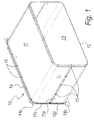
- Figure 1 is a perspective view of a muffle according to the invention;
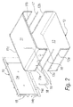
- Figure 2 is an exploded perspective view of a muffle according to the invention;
- Figure 3 is a sectional side view of a portion of a cooking oven particularly for food and the like;
- Figure 4 is an exploded perspective view of a detail of the portion shown in Figure 3.
- With reference to the figures, an improved muffle for cooking ovens particularly for food and the like according to the invention is generally designated by the
reference numeral 10. - The
muffle 10 is constituted by twoparts - Those two parts, a first
upper part 11 and a secondlower part 12, face each other with their respective concavities so as to form acooking compartment 13. - The
compartment 13 is closed at the rear by aback 14. - The two
parts reference numerals first part - The
first part 11 also has arear flap 11c for connection to a correspondingperimetric flap 14c of theback 14. - Likewise, the
second part 12 is provided with arear flap 12c, which is also suitable for connection to theperimetric flap 14c of theback 14. - Therefore, the
lateral flaps rear flaps perimetric flaps 14c of theback 14. - Such pairs of flaps are mutually locked by way of connecting means.
- The connecting means are constituted by a plurality of threaded
elements 15, of the screw-and-nut type, for fastening the interposed flaps. - Moreover, between the
lateral flaps first part 11 and the facingflaps second part 12 there are gasket elements, which are suitable to contain the escape of hot air from themuffle 10. - Likewise, additional gasket elements are interposed between the lower profile of the
perimetric flaps 14c of the back and therear flaps 12c of thesecond part 12. - The gasket elements and additional gasket elements are constituted by strips of plastic material, respectively designated by the
reference numerals - The
strip 18 is substantially U-shaped, so as to mate with the lower profile of theback 14 and with thelower flaps 12c. - A
muffle 10 assembled with connecting means such as the ones described allows to avoid expensive welding and enameling operations, with evident advantages in terms of labor and material costs, as well as in terms of manufacturing time. - The invention also relates to a cooking oven, of the type that comprises supporting
feet 20 fixed to thebottom 22 of the box-like shell 21 of the oven. - The
feet 20 are coupled to thebottom 22 by way of snap-acting engagement means. - In known types of cooking oven, the engagement means are constituted by two elastically
deformable tabs 24 provided with agrip tooth 25. - The
tabs 24 enter with a snap action complementarily shapedslots 26 that are open on thebottom 22 of theshell 21. - The
slots 26 necessarily have a larger cross-section than thetab 24 below the grip tooth. - Inevitably, therefore, the
tab 24 is arranged in thecorresponding slot 26 with a certain play, which is harmful when it is necessary to drag the oven for any reason. - In this case, since the
tabs 24 can move freely within theirslot 26, the tabs may tilt together with thefoot 20 of which they are part. - This is all detrimental to the overall stability of the oven; moreover, the
tilted tab 24 subjected to the weight of the oven runs the risk of flexing beyond its elastic capacity and of undergoing irreparable damage. - The breakage of a
tab 24 can entail the separation of afoot 20 and a consequent unstable configuration of the oven. - In the
oven 30 according to the invention, aprotrusion 27 is provided between thetabs 24 and enters without play acorresponding hole 28 in thebottom 22. - The
protrusion 27 is substantially a cylindrical pin. - The
protrusion 27 prevents the tilting of thefoot 20, facilitating the integrity of thetabs 24 and therefore the stability of theoven 30. - In practice it has been found that the invention thus described solves the problems noted in known types of muffle.
- In particular, the present invention provides an improved muffle for cooking ovens particularly for food and the like that can be assembled easily more rapidly and cheaply than known types of muffle.
- Moreover, the present invention provides an improved muffle in which the heat retention characteristics are not lower than in known muffles.
- Further, the present invention provides a muffle that can be installed easily even in known and already commercially available oven types.
- Moreover, the present invention provides an improved muffle that can be manufactured with known systems and technologies.
- Further, the present invention also provides a cooking oven particularly for food and the like that is provided with supporting feet that are stronger and more stable than in known types of oven.
- The invention thus conceived is susceptible of numerous modifications and variations, all of which are within the scope of the appended claims; all the details may further be replaced with other technically equivalent elements.
- In practice, the materials employed, so long as they are compatible with the specific use, as well as the dimensions, may be any according to requirements and to the state of the art.
- The disclosures in Italian Patent Application No. PD2004A000270 from which this application claims priority are incorporated herein by reference.
- Where technical features mentioned in any claim are followed by reference signs, those reference signs have been included for the sole purpose of increasing the intelligibility of the claims and accordingly such reference signs do not have any limiting effect on the interpretation of each element identified by way of example by such reference signs.
Claims (5)
- An improved muffle for cooking ovens particularly for food and the like, of the type constituted by two substantially C-shaped parts (11, 12), which face each other with their respective concavities so as to form a cooking compartment (13), which is closed at the rear by a back (14), said two parts (11, 12) being connected to each other and to said back (14) by way of corresponding flaps (11a, 11b, 11c, 12a, 12b, 12c, 14a, 14b, 14c) that are coupled by way of connecting means, said improved muffle (10) being characterized that said connecting means are constituted by threaded elements (15), gasket elements suitable to contain the escape of hot air from said muffle (10) being interposed between the lateral connecting flaps (11a, 11b, 12a, 12b) of said two parts (11, 12) and between at least part of the rear flaps (11c, 12c) of the two parts (11, 12) and the flaps (14c) of the back (14).
- The improved muffle according to claim 1, characterized in that said gasket elements are constituted by strips (16, 17, 18) made of plastic material.
- The muffle according to one or more of the preceding claims, characterized in that it is provided with a gasket strip (18) between the rear flaps (12c) of the lower part (12) of the muffle (10) and the corresponding flaps (14c) of said back (14).
- The cooking oven particularly for food and the like, of the type that comprises supporting feet (20), which are fixed to the bottom (22) of the box-like shell (21) of the oven by way of snap-acting engagement means, which are constituted, for each foot (20), by two elastically deformable tabs (24) provided with a grip tooth (25), said tabs (24) being suitable to enter with a snap action complementarily shaped slots (26) that are open on the bottom (22) of said shell (21), said oven (30) being characterized in that between said tabs (24) there is a protrusion (27), which is suitable to enter without play a corresponding hole (28) in said bottom (22).
- The oven according to claim 4, characterized in that said protrusion (27) is substantially a cylindrical pin.
Applications Claiming Priority (1)
| Application Number | Priority Date | Filing Date | Title |
|---|---|---|---|
| ITPD20040270 ITPD20040270A1 (en) | 2004-11-03 | 2004-11-03 | PERFECT STRUCTURE OF MUFFLE |
Publications (2)
| Publication Number | Publication Date |
|---|---|
| EP1655544A2 true EP1655544A2 (en) | 2006-05-10 |
| EP1655544A3 EP1655544A3 (en) | 2008-04-30 |
Family
ID=35717570
Family Applications (1)
| Application Number | Title | Priority Date | Filing Date |
|---|---|---|---|
| EP05109367A Withdrawn EP1655544A3 (en) | 2004-11-03 | 2005-10-07 | Muffle for a cooking oven |
Country Status (2)
| Country | Link |
|---|---|
| EP (1) | EP1655544A3 (en) |
| IT (1) | ITPD20040270A1 (en) |
Cited By (7)
| Publication number | Priority date | Publication date | Assignee | Title |
|---|---|---|---|---|
| US20090301460A1 (en) * | 2008-05-29 | 2009-12-10 | Wolfgang Schmidbauer | Oven muffle |
| WO2010029088A1 (en) * | 2008-09-12 | 2010-03-18 | Arcelik Anonim Sirketi | An oven casing assembly |
| EP2196735A2 (en) | 2008-12-12 | 2010-06-16 | BSH Bosch und Siemens Hausgeräte GmbH | Muffle for a cooking device |
| US8132500B2 (en) | 2008-04-04 | 2012-03-13 | Illinois Tool Works Inc. | Humidity controlled food warming cabinet |
| WO2016150457A1 (en) * | 2015-03-20 | 2016-09-29 | Electrolux Appliances Aktiebolag | Oven muffle for a domestic oven |
| EP3608594A1 (en) | 2018-08-10 | 2020-02-12 | Bonferraro S.p.A. | Muffle for convection oven and oven comprising said muffle |
| WO2022148592A1 (en) * | 2021-01-06 | 2022-07-14 | BSH Hausgeräte GmbH | Household cooking appliance including a non-welded oven cavity having a seal allowing pyrolytic cleaning |
Family Cites Families (4)
| Publication number | Priority date | Publication date | Assignee | Title |
|---|---|---|---|---|
| BE407506A (en) * | 1935-01-25 | 1935-02-28 | ||
| US3036192A (en) * | 1958-10-15 | 1962-05-22 | Gen Motors Corp | Removable oven liner |
| CA1184458A (en) * | 1981-06-16 | 1985-03-26 | Noboru Igarashi | Construction of heating compartment for cooking apparatus |
| FR2686277B1 (en) * | 1992-01-17 | 1995-06-16 | Moulinex Sa | PROCESS OF CONFORMING A SHEET IN AT LEAST ONE DIEDRE OF WHICH BOTH INTERNAL FACES RECEIVE A COATING OF ENAMEL AND OVEN ENCLOSURE OBTAINED BY THIS PROCESS. |
-
2004
- 2004-11-03 IT ITPD20040270 patent/ITPD20040270A1/en unknown
-
2005
- 2005-10-07 EP EP05109367A patent/EP1655544A3/en not_active Withdrawn
Cited By (8)
| Publication number | Priority date | Publication date | Assignee | Title |
|---|---|---|---|---|
| US8132500B2 (en) | 2008-04-04 | 2012-03-13 | Illinois Tool Works Inc. | Humidity controlled food warming cabinet |
| US20090301460A1 (en) * | 2008-05-29 | 2009-12-10 | Wolfgang Schmidbauer | Oven muffle |
| US8794226B2 (en) * | 2008-05-29 | 2014-08-05 | Schott Ag | Oven muffle |
| WO2010029088A1 (en) * | 2008-09-12 | 2010-03-18 | Arcelik Anonim Sirketi | An oven casing assembly |
| EP2196735A2 (en) | 2008-12-12 | 2010-06-16 | BSH Bosch und Siemens Hausgeräte GmbH | Muffle for a cooking device |
| WO2016150457A1 (en) * | 2015-03-20 | 2016-09-29 | Electrolux Appliances Aktiebolag | Oven muffle for a domestic oven |
| EP3608594A1 (en) | 2018-08-10 | 2020-02-12 | Bonferraro S.p.A. | Muffle for convection oven and oven comprising said muffle |
| WO2022148592A1 (en) * | 2021-01-06 | 2022-07-14 | BSH Hausgeräte GmbH | Household cooking appliance including a non-welded oven cavity having a seal allowing pyrolytic cleaning |
Also Published As
| Publication number | Publication date |
|---|---|
| ITPD20040270A1 (en) | 2005-02-03 |
| EP1655544A3 (en) | 2008-04-30 |
Similar Documents
| Publication | Publication Date | Title |
|---|---|---|
| EP2716977B1 (en) | Cooking oven | |
| US8899426B2 (en) | Half rack | |
| KR20140109074A (en) | A Electronic Roaster | |
| CA2597187C (en) | Full depth rack | |
| EP4064944B1 (en) | Cooking appliance | |
| US6713740B2 (en) | Microwave oven having heaters for cooking food | |
| EP2520133A1 (en) | An oven | |
| EP1913308A2 (en) | A cooking device | |
| CA2447108C (en) | One-piece burner element/switch support for a cooktop | |
| CN219699701U (en) | Air flow sealing structure of double-pot heating cavity and double-pot independent control type air fryer | |
| EP1764559B1 (en) | Cooking grate assembly | |
| CA2307691A1 (en) | Shell structure for a heating appliance, and method of manufacturing heating appliance including same | |
| JP2001153372A (en) | Electric oven and liner used for it | |
| KR100850019B1 (en) | A Mounting Structure Of Rack Shelf for Microwave Oven | |
| KR102331673B1 (en) | Electric cooker | |
| US20030178420A1 (en) | Microwave oven with increased usable space | |
| KR200253016Y1 (en) | structure for maintain gap between outer panel and inner panel of door in gas oven range | |
| KR100705066B1 (en) | Double bottom fixed structure of electric oven | |
| US20050217500A1 (en) | Multi-use rack | |
| CN220494857U (en) | Air frying pan | |
| US9546791B2 (en) | Cooking appliance | |
| EP4235033A1 (en) | Oven with tilting broiler assembly | |
| KR200349588Y1 (en) | warming drawer in gas ovenrange | |
| US20250172295A1 (en) | Home appliance | |
| KR100682675B1 (en) | Double bottom fixed structure of electric oven |
Legal Events
| Date | Code | Title | Description |
|---|---|---|---|
| PUAI | Public reference made under article 153(3) epc to a published international application that has entered the european phase |
Free format text: ORIGINAL CODE: 0009012 |
|
| AK | Designated contracting states |
Kind code of ref document: A2 Designated state(s): AT BE BG CH CY CZ DE DK EE ES FI FR GB GR HU IE IS IT LI LT LU LV MC NL PL PT RO SE SI SK TR |
|
| AX | Request for extension of the european patent |
Extension state: AL BA HR MK YU |
|
| RAP1 | Party data changed (applicant data changed or rights of an application transferred) |
Owner name: UNOX S.R.L. |
|
| PUAL | Search report despatched |
Free format text: ORIGINAL CODE: 0009013 |
|
| AK | Designated contracting states |
Kind code of ref document: A3 Designated state(s): AT BE BG CH CY CZ DE DK EE ES FI FR GB GR HU IE IS IT LI LT LU LV MC NL PL PT RO SE SI SK TR |
|
| AX | Request for extension of the european patent |
Extension state: AL BA HR MK YU |
|
| AKX | Designation fees paid | ||
| REG | Reference to a national code |
Ref country code: DE Ref legal event code: 8566 |
|
| STAA | Information on the status of an ep patent application or granted ep patent |
Free format text: STATUS: THE APPLICATION IS DEEMED TO BE WITHDRAWN |
|
| 18D | Application deemed to be withdrawn |
Effective date: 20081031 |