EP1655414A1 - Icebreaker and waterway with icebreaker - Google Patents
Icebreaker and waterway with icebreaker Download PDFInfo
- Publication number
- EP1655414A1 EP1655414A1 EP04770922A EP04770922A EP1655414A1 EP 1655414 A1 EP1655414 A1 EP 1655414A1 EP 04770922 A EP04770922 A EP 04770922A EP 04770922 A EP04770922 A EP 04770922A EP 1655414 A1 EP1655414 A1 EP 1655414A1
- Authority
- EP
- European Patent Office
- Prior art keywords
- film body
- expandable
- shrinkable film
- icebreaker
- channel
- Prior art date
- Legal status (The legal status is an assumption and is not a legal conclusion. Google has not performed a legal analysis and makes no representation as to the accuracy of the status listed.)
- Withdrawn
Links
Images




Classifications
-
- E—FIXED CONSTRUCTIONS
- E02—HYDRAULIC ENGINEERING; FOUNDATIONS; SOIL SHIFTING
- E02B—HYDRAULIC ENGINEERING
- E02B1/00—Equipment or apparatus for, or methods of, general hydraulic engineering, e.g. protection of constructions against ice-strains
- E02B1/003—Mechanically induced gas or liquid streams in seas, lakes or water-courses for forming weirs or breakwaters; making or keeping water surfaces free from ice, aerating or circulating water, e.g. screens of air-bubbles against sludge formation or salt water entry, pump-assisted water circulation
-
- E—FIXED CONSTRUCTIONS
- E02—HYDRAULIC ENGINEERING; FOUNDATIONS; SOIL SHIFTING
- E02B—HYDRAULIC ENGINEERING
- E02B7/00—Barrages or weirs; Layout, construction, methods of, or devices for, making same
- E02B7/20—Movable barrages; Lock or dry-dock gates
Definitions
- the present invention relates to an icebreaker which can break through ice formed when water at a channel is frozen, and to a channel having the icebreaker.
- Patent Document 1 Japanese Patent Application (JP-A) Laid-Open No. 2002-285533. Disclosure of the Invention Problems to be Solved by the Invention
- An object of the invention is to provide an icebreaker having a simple structure for breaking through ice formed at a channel, and a channel having the icebreaker.
- the invention according to claim 1 is an icebreaker for breaking through an ice formed at a channel, comprising an expandable/shrinkable film body which is disposed along a wall surface of the channel, a fixing member for fixing the expandable/shrinkable film body to the wall surface, and an air-supply means for supplying air to between the expandable/shrinkable film body and the wall surface to inflate the expandable/shrinkable film body at the channel inner side.
- the expandable/shrinkable film body is disposed along the wall surface of the channel.
- the air supplying means When temperature goes down, and for example, ice is formed on the water surface of the channel, the air supplying means is operated to inflate the extendable and/or contractive film body.
- the invention according to claim 2 is the icebreaker according to claim 1, further comprising a lower film body provided in close contact with the wall surface, wherein the air-supplying means supplies air to between the expandable/shrinkable film body and the lower film body.
- air is supplied to between the expandable/shrinkable film body and the lower film body to thereby inflate the expandable/shrinkable film body.
- Claim 3 is a channel provided with an ice breaker, comprising a channel, a gate for opening/closing the channel, and the ice breaker according to claim 1 or 2 disposed near the gate of the channel.
- the air-supplying means When temperature goes down, and ice is formed on the water surface in vicinities of the gates, the air-supplying means is operated to inflate the expandable/shrinkable means.
- the icebreaker of the present invention can provide an excellent effect in that, with a simple structure, the icebreaker can break through ice formed at a channel.
- the channel having the icebreaker of the present invention is structured as described above, an excellent effect is provided in that, with a simple structure, ice formed at a channel can be broken to open/close the gates freely.
- a canal 10 is equipped with a gate 12 which is opened/closed in a direction of arrow C.
- the gate 12 drawn by a solid line represent a closed state of the canal 10
- the gate 12 drawn by a double-dashed line represents an opened state thereof.
- Wall surfaces 14 are formed by a material such as a concrete, and disposed at both sides of the canal 10. Icebreaker main bodies 16 are formed at the wall surfaces 14, respectively, at a side to which the gate 12 is opened.
- each icebreaker main body 16 has a rectangular expandable/shrinkable film body 18 which is elongated in the horizontal direction (direction of arrow B in Fig. 3).
- the expandable/shrinkable film body 18 is formed as a canvas-like member in which fabric materials 19a and 19b are woven in warp/weft directions and covered with an elastic member 21 such as a rubber provided thereon.
- the fabric materials 19a arranged in a warp direction (direction of arrow A corresponding to the vertical direction of the canal 10) extends in a wavy manner
- the fabric materials 19b arranged in a weft direction (direction of arrow B corresponding to the horizontal direction of the canal 10) extend substantially linearly.
- the expandable/shrinkable film body 18 is not stretched so much in the direction of arrow B but can be stretched well in the direction of arrow A due to a linear expansion of the fabric materials 19a.
- a built-in fitting 20 is disposed along an outer peripheral edge of the expandable/shrinkable film body 18 on each wall surfaces 14, and anchor bolts 22 are also arranged thereon so as to be spaced apart from each other at a predetermined interval thereon.
- the anchor bolts 22 are inserted into holes 15 formed on the wall surface 14. Due to a solidification of an adhesive (such as an epoxy resin) 17 with which the holes 15 are filled, the anchor bolts 22 are fixed to the wall surface 14.
- an adhesive such as an epoxy resin
- anchor bolts 22 are passed through the built-in fitting 20.
- An end portion of the extendable and/or contractive film body 18 is disposed on the built-in fitting 20, and the anchor bolts 22 are passed through the expandable/shrinkable film body 18.
- Tap fittings 24 are mounted on the expandable/shrinkable film body 18. Nuts 26 are screwed, through spring washers 25, onto upper end portions of the anchor bolts 22 which are passed through the tap fittings 24. The outer peripheral edge portion of the expandable/shrinkable film body 18 is thus nipped between the tap fittings 24 and the built-in fitting 20, and fixed to the wall surface 14.
- an air pipe 28 is embedded in the wall surface 14.
- One end of the air pipe 28 is open toward the wall surface 14 to face the inner surface of the expandable/shrinkable film body 18.
- an air-supply valve 30 To the other side of the air pipe 28 are mounted an air-supply valve 30, an air-discharge valve 31, a compressor 32, a check valve 33, a pressure gage 34, and an open/close valve 35.
- air-discharge valve 31 When the air-discharge valve 31 is closed and the air-supply valve 30 is opened, air can be supplied from the compressor 32 into the expandable/shrinkable film body 18, and when the air-discharge valve 31 is opened, air can be discharged from the expandable/shrinkable film body 18.
- check valve 33 and the pressure gage 34 which are installed at the air pipe 28 are controlled to prevent a reverse flow of the supplied air and an excessive pressure. Pressure is checked by opening the open/close valve 35.
- motor valves can be used as the air-supply valve 30 and the air-discharge valve 31. (Operation) Next, an operation of the present embodiment will be described.
- the expandable/shrinkable film bodies 18 are disposed along the wall surfaces 14 of the canal 10. Accordingly, the gate 12 can be opened/closed smoothly.
- a water level of the canal 10 according to the present embodiment changes in a horizontal direction.
- a water level 34a drawn by a solid line shows a high water level
- a water level 34b drawn by a double-dashed line shows a low water level.
- the expandable/shrinkable film body 18 may be inflated by about 300mm at the central portion thereof.
- the ice 36 which is formed on the water surface of the water 34 is pressed by the inflating expandable/shrinkable film body 18 and crashed, whereby the gate 12 can be opened/closed smoothly.
- the ice 36 Since the working operation for crashing the ice 36 requires only the operations of the compressor 32, the air-supply valve 30 and the air-discharge valve 31, the ice 36 can be crashed easily.
- the icebreaker main body 16 must be set so as to meet the level of the water at which the ice 36 is formed, and the expandable/shrinkable film body 18 must be measured so as to reliably break the ice 36.
- the expandable/shrinkable film body 18 Since the expandable/shrinkable film body 18 is deformed or expanded by inflation, the expandable/shrinkable film body 18 thus inflated is returned to the original flat shape by itself or by the shrinking force thereof when the air inside the expandable/shrinkable film body 18 is discharged.
- air within the expandable/shrinkable film body 18 can be forcibly discharged by using a pump or the like.
- the icebreaker main body 16 is disposed only at the side to which the gate 12 is opened. However, the icebreaker main body 16 may further be added at the other side of the gate 12.
- a pressure control valve (not shown) to the compressor 32 in order to prevent an unnecessarily high pressure from acting on the expandable/shrinkable film member 18.
- a lower film body 38 which is formed from an elastic body such as a rubber and which has the same size as that of the expandable/shrinkable film body 18, is provided so as to be in close contact with the wall surface 14, and the expandable/shrinkable film body 18 is mounted on the lower film body 38.
- both the lower film body 38 and the expandable/shrinkable film body 18 are nipped between the built-in fitting 20 and the tap fittings 24, and fixed to the wall surface 14.
- a flat donut-shaped fastening member 40 is embedded in the wall surface 14 at the end portion of the air pipe 28.
- a female thread 42 is formed at the inside of the flat donut-shaped fastening member 40, and a male thread 46 of a tap fitting 44 is screwed through the lower film body 38 and a washer 45 into the female screw 42.
- the tap fitting 44 has a disk-shaped flange 48 whose diameter is larger than that of an annular seal rib 47 of the tap fitting 40, and the lower film body 38 is nipped between the tap fitting 40 and the washer 45.
- a through hole 50 for air communication is formed at the axial core portion of the tap fitting 44.
- the expandable/shrinkable film body 18 is brought into contact with the lower film body 38 as an elastic body, and a space into which air is blown is positioned between the expandable/shrinkable film body 18 as an elastic body and the lower film body as an elastic body.
- air tightness is very high and leakage of air can be reliably prevented.
- the present invention can be suitably used when cracks are formed on the wall surface 14.
- the expandable/shrinkable film body 18 before being inflated has a flat rectangular configuration whose four corners have been chamfered.
- the flat configuration of the expandable/shrinkable film body 18 is not limited to this, and, as shown in Fig. 10, it can be formed into another configuration such as a substantially O-shaped or an ellipsoidal configuration.
- a recessed portion 52 for accommodating the gate 12 is formed at the wall surface 14 of the canal 10, and the icebreaker main body 16 is provided at the recessed portion 52.
- the recessed portion 52 need not be formed at the wall surface 14.
Landscapes
- Engineering & Computer Science (AREA)
- General Engineering & Computer Science (AREA)
- Structural Engineering (AREA)
- Mechanical Engineering (AREA)
- Civil Engineering (AREA)
- Barrages (AREA)
- Tents Or Canopies (AREA)
Abstract
An icebreaker main body 16 in which an expandable/shrinkable film body 18 is fixed, by fittings, to a wall surface 14 of a canal 10 is provided near a gate. When an ice 36 is formed in the vicinity of the surface of water 34 of the canal 10, air is supplied from a compressor 32 into the expandable/shrinkable film body 18 to inflate the expandable/shrinkable film body 18. The ice 36 is crashed due to a pressure applied from the inflating expandable/shrinkable film body 18, whereby the gate can be opened/closed smoothly.
Description
- The present invention relates to an icebreaker which can break through ice formed when water at a channel is frozen, and to a channel having the icebreaker.
- For example, steel gates are disposed at a channel such as a canal in order to open/close the channel (See Document 1)
Patent Document 1: Japanese Patent Application (JP-A) Laid-Open No. 2002-285533.
Disclosure of the Invention
Problems to be Solved by the Invention - Typically, power outputted from a motor or the like is used in order to open/close gates. However, when water at a channel is frozen in winter time, it often becomes difficult to open/close the gates smoothly.
- It is considered that certain types of apparatuses may be used in order to break through the ice. However, the operation requires much time and labors, and a high cost performance as well, which is not practical. Besides, it will take considerable time to open/close the gates.
- As a result of assiduous study for solving such a problem as described above with a conventional art, the present inventors have now completed the present invention. An object of the invention is to provide an icebreaker having a simple structure for breaking through ice formed at a channel, and a channel having the icebreaker.
- The invention according to claim 1 is an icebreaker for breaking through an ice formed at a channel, comprising an expandable/shrinkable film body which is disposed along a wall surface of the channel, a fixing member for fixing the expandable/shrinkable film body to the wall surface, and an air-supply means for supplying air to between the expandable/shrinkable film body and the wall surface to inflate the expandable/shrinkable film body at the channel inner side.
- Next, an operation of the icebreaker according to claim 1 will be described.
- At an ordinary time, the expandable/shrinkable film body is disposed along the wall surface of the channel.
- When temperature goes down, and for example, ice is formed on the water surface of the channel, the air supplying means is operated to inflate the extendable and/or contractive film body.
- As a result, ice formed on the water surface is pressed by the inflating expandable/shrinkable film body and crashed (broken).
- After the expandable/shrinkable film body has been used, air is discharged from the expandable/shrinkable film body so that the expandable/shrinkable film body recovers its original shape such that it is disposed along the water surface of the channel.
- The invention according to claim 2 is the icebreaker according to claim 1, further comprising a lower film body provided in close contact with the wall surface, wherein the air-supplying means supplies air to between the expandable/shrinkable film body and the lower film body.
- Next, an operation of the icebreaker according to claim 2 will be described.
- In accordance with the icebreaker according to claim 2, air is supplied to between the expandable/shrinkable film body and the lower film body to thereby inflate the expandable/shrinkable film body.
- Since air is supplied to between the expandable/shrinkable film body and the under film body, air tightness is significantly improved.
- Claim 3 is a channel provided with an ice breaker, comprising a channel, a gate for opening/closing the channel, and the ice breaker according to claim 1 or 2 disposed near the gate of the channel.
- Next, an operation of the channel having the icebreaker according to claim 3 will be described.
- When temperature goes down, and ice is formed on the water surface in vicinities of the gates, the air-supplying means is operated to inflate the expandable/shrinkable means.
- As a result, ice formed on the water surface is pressed by the inflating expandable/shrinkable means, and crashed (broken), whereby the gates can be opened/closed.
- As described above, the icebreaker of the present invention can provide an excellent effect in that, with a simple structure, the icebreaker can break through ice formed at a channel.
- Further, since the channel having the icebreaker of the present invention is structured as described above, an excellent effect is provided in that, with a simple structure, ice formed at a channel can be broken to open/close the gates freely.
-
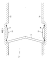
- Fig. 1 is a cross-sectional view of a canal according to a first embodiment of the present invention;
- Fig. 2 is a plan view of the canal;
- Fig. 3 is a front view of an ice breaker main body;
- Fig. 4 is a perspective view of an expandable/shrinkable film body;
- Fig. 5 is a cross-sectional view of a portion at which the expandable/shrinkable film body is attached;
- Fig. 6 is a cross-sectional view of an icebreaker main body;
- Fig. 7 is a plan view of a canal in a state in which the icebreaker has been inflated;
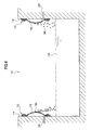
- Fig. 8 is a cross-sectional view of the canal showing a state in which ice deposited at the surface of the expandable/shrinkable film body is being peeled off therefrom;
- Fig. 9(A) is a cross-sectional view of an icebreaker main body according to a second embodiment of the present invention;
- Fig. 9(B) is a front view of an edge portion of an air pipe;
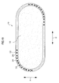
- Fig. 10 is a front view of an ice breaker main body according to another embodiment of the present invention; and
- Fig. 11 is a plan view of a canal according to another embodiment of the present invention.
- With reference to the drawings, a channel provided with an icebreaker according to a first embodiment of the present invention will be described hereinafter.
- As shown in Fig. 2, a
canal 10 is equipped with agate 12 which is opened/closed in a direction of arrow C. In Fig. 2, thegate 12 drawn by a solid line represent a closed state of thecanal 10, while thegate 12 drawn by a double-dashed line represents an opened state thereof. -
Wall surfaces 14 are formed by a material such as a concrete, and disposed at both sides of thecanal 10. Icebreakermain bodies 16 are formed at thewall surfaces 14, respectively, at a side to which thegate 12 is opened. - As shown in Figs. 1 and 3, each icebreaker
main body 16 has a rectangular expandable/shrinkable film body 18 which is elongated in the horizontal direction (direction of arrow B in Fig. 3). - As shown in Fig. 4, the expandable/
shrinkable film body 18 is formed as a canvas-like member in whichfabric materials elastic member 21 such as a rubber provided thereon. Thefabric materials 19a arranged in a warp direction (direction of arrow A corresponding to the vertical direction of the canal 10) extends in a wavy manner, and thefabric materials 19b arranged in a weft direction (direction of arrow B corresponding to the horizontal direction of the canal 10) extend substantially linearly. - Consequently, the expandable/
shrinkable film body 18 is not stretched so much in the direction of arrow B but can be stretched well in the direction of arrow A due to a linear expansion of thefabric materials 19a. - As shown in Figs. 3 and 5, a built-in
fitting 20 is disposed along an outer peripheral edge of the expandable/shrinkable film body 18 on eachwall surfaces 14, andanchor bolts 22 are also arranged thereon so as to be spaced apart from each other at a predetermined interval thereon. - The
anchor bolts 22 are inserted intoholes 15 formed on thewall surface 14. Due to a solidification of an adhesive (such as an epoxy resin) 17 with which theholes 15 are filled, theanchor bolts 22 are fixed to thewall surface 14. - Further, the
anchor bolts 22 are passed through the built-in fitting 20. - An end portion of the extendable and/or
contractive film body 18 is disposed on the built-in fitting 20, and theanchor bolts 22 are passed through the expandable/shrinkable film body 18. -
Tap fittings 24 are mounted on the expandable/shrinkable film body 18.Nuts 26 are screwed, throughspring washers 25, onto upper end portions of theanchor bolts 22 which are passed through thetap fittings 24. The outer peripheral edge portion of the expandable/shrinkable film body 18 is thus nipped between thetap fittings 24 and the built-infitting 20, and fixed to thewall surface 14. - As shown in Fig. 6, an
air pipe 28 is embedded in thewall surface 14. - One end of the
air pipe 28 is open toward thewall surface 14 to face the inner surface of the expandable/shrinkable film body 18. - To the other side of the
air pipe 28 are mounted an air-supply valve 30, an air-discharge valve 31, acompressor 32, acheck valve 33, apressure gage 34, and an open/close valve 35. - When the air-
discharge valve 31 is closed and the air-supply valve 30 is opened, air can be supplied from thecompressor 32 into the expandable/shrinkable film body 18, and when the air-discharge valve 31 is opened, air can be discharged from the expandable/shrinkable film body 18. - Moreover, the
check valve 33 and thepressure gage 34 which are installed at theair pipe 28 are controlled to prevent a reverse flow of the supplied air and an excessive pressure. Pressure is checked by opening the open/close valve 35. - Further, for the convenience in use, motor valves can be used as the air-
supply valve 30 and the air-discharge valve 31.
(Operation)
Next, an operation of the present embodiment will be described. - As shown in Figs. 1 and 2, at an ordinary time, the expandable/
shrinkable film bodies 18 are disposed along the wall surfaces 14 of thecanal 10. Accordingly, thegate 12 can be opened/closed smoothly. - A water level of the
canal 10 according to the present embodiment changes in a horizontal direction. In Fig. 1, awater level 34a drawn by a solid line shows a high water level, and awater level 34b drawn by a double-dashed line shows a low water level. - For example, when the water level is high at the
water level 34a and the temperature has dropped while thegate 12 is closed, whereby, as shown in Fig. 6, anice 36 has been formed on thewater surface 34 of thecanal 10, air is supplied from thecompressor 32 to the expandable/shrinkable film body 18. As a result, as shown in Fig. 7, the expandable/shrinkable film body 18 is inflated. - For example, in a case in which the expandable/
shrinkable film body 18 is sized to a width of 3200mm x a length of 915mm, if the pressure within the expandable/shrinkable film body 18 is about 30.0Kpa, the expandable/shrinkable film body 18 may be inflated by about 300mm at the central portion thereof. - By this, the
ice 36 which is formed on the water surface of thewater 34 is pressed by the inflating expandable/shrinkable film body 18 and crashed, whereby thegate 12 can be opened/closed smoothly. - Since the working operation for crashing the
ice 36 requires only the operations of thecompressor 32, the air-supply valve 30 and the air-discharge valve 31, theice 36 can be crashed easily. - Needless to say, the icebreaker
main body 16 must be set so as to meet the level of the water at which theice 36 is formed, and the expandable/shrinkable film body 18 must be measured so as to reliably break theice 36. - After the use of the expandable/
shrinkable film body 18, air is discharged from the expandable/shrinkable film body 18, whereby the expandable/shrinkable film body 18 recovers its original shape such that it is disposed along thewall surface 14. - Since the expandable/
shrinkable film body 18 is deformed or expanded by inflation, the expandable/shrinkable film body 18 thus inflated is returned to the original flat shape by itself or by the shrinking force thereof when the air inside the expandable/shrinkable film body 18 is discharged. - Further, air within the expandable/
shrinkable film body 18 can be forcibly discharged by using a pump or the like. - As shown in Fig. 8, there is a possibility that the
ice 36 is deposited to the surface of the expandable/shrinkable film body 18 itself. In such a case, it suffices to simply inflate the expandable/shrinkable film body 18 in order to peel off and drop theice 36 from the expandable/shrinkable film body 18. - In the present embodiment, the icebreaker
main body 16 is disposed only at the side to which thegate 12 is opened. However, the icebreakermain body 16 may further be added at the other side of thegate 12. - Further, it is preferable to attach in advance a pressure control valve (not shown) to the
compressor 32 in order to prevent an unnecessarily high pressure from acting on the expandable/shrinkable film member 18.
(Second embodiment)
With reference to the drawing, a channel having an icebreaker according to a second embodiment of the present invention will be described next. Further, portions identical to those in the first embodiment of the present invention are denoted by the same reference numerals and descriptions thereof will be omitted. - As shown in Fig. 9(A), in the icebreaker
main body 16 according to the present embodiment, alower film body 38, which is formed from an elastic body such as a rubber and which has the same size as that of the expandable/shrinkable film body 18, is provided so as to be in close contact with thewall surface 14, and the expandable/shrinkable film body 18 is mounted on thelower film body 38. - Since no inflation of the
lower film body 38 is carried out, it is unnecessary for thelower film body 38 to be capable of expanding as is the case with the expandable/shrinkable film body 18. - Further, both the
lower film body 38 and the expandable/shrinkable film body 18 are nipped between the built-in fitting 20 and thetap fittings 24, and fixed to thewall surface 14. - As shown in Fig. 9(B), a flat donut-shaped
fastening member 40 is embedded in thewall surface 14 at the end portion of theair pipe 28. - A
female thread 42 is formed at the inside of the flat donut-shapedfastening member 40, and amale thread 46 of a tap fitting 44 is screwed through thelower film body 38 and awasher 45 into thefemale screw 42. - The tap fitting 44 has a disk-shaped
flange 48 whose diameter is larger than that of anannular seal rib 47 of the tap fitting 40, and thelower film body 38 is nipped between the tap fitting 40 and thewasher 45. - A through
hole 50 for air communication is formed at the axial core portion of the tap fitting 44. - In the present embodiment, the expandable/
shrinkable film body 18 is brought into contact with thelower film body 38 as an elastic body, and a space into which air is blown is positioned between the expandable/shrinkable film body 18 as an elastic body and the lower film body as an elastic body. Thus, air tightness is very high and leakage of air can be reliably prevented. - Consequently, the present invention can be suitably used when cracks are formed on the
wall surface 14.
(Another embodiment)
In the above-described embodiment as shown in Fig. 3, the expandable/shrinkable film body 18 before being inflated has a flat rectangular configuration whose four corners have been chamfered. However, the flat configuration of the expandable/shrinkable film body 18 is not limited to this, and, as shown in Fig. 10, it can be formed into another configuration such as a substantially O-shaped or an ellipsoidal configuration. - Further, in the aforementioned embodiment, a recessed
portion 52 for accommodating thegate 12 is formed at thewall surface 14 of thecanal 10, and the icebreakermain body 16 is provided at the recessedportion 52. However, as shown in Fig. 11, the recessedportion 52 need not be formed at thewall surface 14.
Industrial Availability
The present invention can be applied, when water in a channel is frozen in winter time, in order to break ice formed at the channel with a simple structure so that a gate provided at the channel can be opened/closed. Description of the reference numerals -
- 10
- channel
- 12
- gate
- 16
- icebreaker main body (ice breaker)
- 28
- air pipe (icebreaker)
- 30
- air-supply valve (icebreaker)
- 31
- air-discharge valve (icebreaker)
- 32
- compressor (icebreaker)
- 33
- check valve (icebreaker)
Claims (3)
- An icebreaker for breaking through an ice formed at a channel, comprising
an expandable/shrinkable film body which is disposed along a wall surface of the channel;
a fixing member for fixing the expandable/shrinkable film body to the wall surface; and
an air-supply means for supplying air to between the expandable/shrinkable film body and the wall surface to inflate the expandable/shrinkable film body at the channel inner side. - The icebreaker according to claim 1, further comprising a lower film body provided in close contact with the wall surface, wherein the air-supplying means supplies air into between the expandable/shrinkable film body and the lower film body.
- A channel provided with an ice breaker, comprising:a channel;a gate for opening/closing the channel; andthe ice breaker according to claim 1 or 2 disposed near the gate of the channel.
Applications Claiming Priority (3)
| Application Number | Priority Date | Filing Date | Title |
|---|---|---|---|
| JP2003201840 | 2003-07-25 | ||
| JP2003288426A JP3950090B2 (en) | 2003-07-25 | 2003-08-07 | Ice breaker |
| PCT/JP2004/010611 WO2005010282A1 (en) | 2003-07-25 | 2004-07-26 | Icebreaker and waterway with icebreaker |
Publications (2)
| Publication Number | Publication Date |
|---|---|
| EP1655414A1 true EP1655414A1 (en) | 2006-05-10 |
| EP1655414A4 EP1655414A4 (en) | 2010-03-24 |
Family
ID=34106842
Family Applications (1)
| Application Number | Title | Priority Date | Filing Date |
|---|---|---|---|
| EP04770922A Withdrawn EP1655414A4 (en) | 2003-07-25 | 2004-07-26 | Icebreaker and waterway with icebreaker |
Country Status (6)
| Country | Link |
|---|---|
| US (1) | US20070025818A1 (en) |
| EP (1) | EP1655414A4 (en) |
| JP (1) | JP3950090B2 (en) |
| CA (1) | CA2533441A1 (en) |
| NO (1) | NO20060394L (en) |
| WO (1) | WO2005010282A1 (en) |
Cited By (2)
| Publication number | Priority date | Publication date | Assignee | Title |
|---|---|---|---|---|
| CN103410117A (en) * | 2013-08-27 | 2013-11-27 | 湖南三楚科技有限公司 | Anti-icing device |
| CN113235526A (en) * | 2021-06-03 | 2021-08-10 | 魏驿明 | Novel hydraulic engineering is with automatic gate of opening and close |
Families Citing this family (4)
| Publication number | Priority date | Publication date | Assignee | Title |
|---|---|---|---|---|
| WO2011011808A1 (en) * | 2009-07-30 | 2011-02-03 | Roman Buga | A cosmetic composition comprising sodium chloride in combination with one or more of protein, collagen, gelatin or amino acid |
| RU2604931C2 (en) * | 2015-05-20 | 2016-12-20 | Аскар Джамилевич Мингажев | Method and device for collecting oil and oil products from under ice cover of water body |
| CN114032852B (en) * | 2021-11-18 | 2023-03-21 | 郑州大学 | Gate ultrasonic wave defroster |
| CN119877449A (en) * | 2025-03-29 | 2025-04-25 | 山西东山水务集团有限公司 | Gate ice melting equipment and gate ice melting method |
Family Cites Families (9)
| Publication number | Priority date | Publication date | Assignee | Title |
|---|---|---|---|---|
| US3698193A (en) * | 1966-04-15 | 1972-10-17 | Stewart F Daymond | Conduits |
| US3690601A (en) * | 1970-09-23 | 1972-09-12 | Lowell W Roemke | Pneumatic deicer periphery bleeder |
| JPS5255836Y2 (en) * | 1972-06-23 | 1977-12-16 | ||
| JPS5872232U (en) * | 1981-11-06 | 1983-05-16 | 日立造船株式会社 | Freeze prevention device for water intake equipment |
| JPS62143727U (en) * | 1986-02-27 | 1987-09-10 | ||
| JPS62276117A (en) * | 1986-05-23 | 1987-12-01 | Kawasaki Heavy Ind Ltd | Reduction of ice pressure load on sluice |
| JPH0619620Y2 (en) * | 1988-02-10 | 1994-05-25 | 三ツ星ベルト株式会社 | Rubber canal |
| MX174055B (en) * | 1990-02-06 | 1994-04-18 | Bell Helicopter Textron Inc | ELECTROMAGNETIC WAVES ATTENUATING STRUCTURE AND DEFROSTER |
| KR101066826B1 (en) * | 2001-07-09 | 2011-09-23 | 헨리 케이 오베르메이어 | Quantity control gates and their actuators |
-
2003
- 2003-08-07 JP JP2003288426A patent/JP3950090B2/en not_active Expired - Fee Related
-
2004
- 2004-07-26 CA CA002533441A patent/CA2533441A1/en not_active Abandoned
- 2004-07-26 US US10/565,628 patent/US20070025818A1/en not_active Abandoned
- 2004-07-26 WO PCT/JP2004/010611 patent/WO2005010282A1/en not_active Ceased
- 2004-07-26 EP EP04770922A patent/EP1655414A4/en not_active Withdrawn
-
2006
- 2006-01-25 NO NO20060394A patent/NO20060394L/en not_active Application Discontinuation
Cited By (2)
| Publication number | Priority date | Publication date | Assignee | Title |
|---|---|---|---|---|
| CN103410117A (en) * | 2013-08-27 | 2013-11-27 | 湖南三楚科技有限公司 | Anti-icing device |
| CN113235526A (en) * | 2021-06-03 | 2021-08-10 | 魏驿明 | Novel hydraulic engineering is with automatic gate of opening and close |
Also Published As
| Publication number | Publication date |
|---|---|
| WO2005010282A1 (en) | 2005-02-03 |
| JP2005060944A (en) | 2005-03-10 |
| CA2533441A1 (en) | 2005-02-03 |
| JP3950090B2 (en) | 2007-07-25 |
| EP1655414A4 (en) | 2010-03-24 |
| US20070025818A1 (en) | 2007-02-01 |
| NO20060394L (en) | 2006-04-10 |
Similar Documents
| Publication | Publication Date | Title |
|---|---|---|
| US5632303A (en) | Wall water hydrant having backflow and back siphonage preventor | |
| US20050029483A1 (en) | Valve seal with pressure relief channels and expansion voids | |
| US20070025818A1 (en) | Icebreaker and waterway with icebreaker | |
| US4398565A (en) | Pipe plugging apparatus | |
| US6338364B1 (en) | Insert for freeze protecting water pipes | |
| US5234034A (en) | Pneumatic plug device | |
| CN113474585B (en) | Freeze-proof valve capable of controlling discharge flow according to temperature | |
| CN211202934U (en) | Long-life high-sealing gate valve | |
| US7171987B2 (en) | Pipe fitting plug | |
| JP6027161B2 (en) | Air valve | |
| EP2807313A1 (en) | Flood protection device | |
| US6036169A (en) | Self alignable threaded cap and threaded pressure relief valve | |
| CN216402589U (en) | Storage device | |
| KR102697803B1 (en) | Anti-freezing burst device of water pipe | |
| CN111945904A (en) | Temporary plugging device for side wall embedded pipe | |
| KR101194158B1 (en) | Nonfreezing for waterworks | |
| JP2005127348A (en) | Gas shutoff device | |
| CN213571807U (en) | Gas shield dam stagnant water structure | |
| JP2004107933A (en) | Air bag type flap gate | |
| CN211574319U (en) | Pipe clamping water closing device | |
| CN221780000U (en) | Inflatable airbag sealing device | |
| CN220037568U (en) | Inflation valve | |
| CN218207815U (en) | Novel sealing element | |
| CN112696038A (en) | Waterproof joint protection device | |
| KR200251157Y1 (en) | draining apparatus for prevention of frozen to burst |
Legal Events
| Date | Code | Title | Description |
|---|---|---|---|
| PUAI | Public reference made under article 153(3) epc to a published international application that has entered the european phase |
Free format text: ORIGINAL CODE: 0009012 |
|
| 17P | Request for examination filed |
Effective date: 20060206 |
|
| AK | Designated contracting states |
Kind code of ref document: A1 Designated state(s): AT BE BG CH CY CZ DE DK EE ES FI FR GB GR HU IE IT LI LU MC NL PL PT RO SE SI SK TR |
|
| DAX | Request for extension of the european patent (deleted) | ||
| A4 | Supplementary search report drawn up and despatched |
Effective date: 20100218 |
|
| 17Q | First examination report despatched |
Effective date: 20101004 |
|
| STAA | Information on the status of an ep patent application or granted ep patent |
Free format text: STATUS: THE APPLICATION IS DEEMED TO BE WITHDRAWN |
|
| 18D | Application deemed to be withdrawn |
Effective date: 20110215 |