EP1653645A1 - A method and device of the estimating carrier frequency offset of subscriber terminal - Google Patents
A method and device of the estimating carrier frequency offset of subscriber terminal Download PDFInfo
- Publication number
- EP1653645A1 EP1653645A1 EP04762035A EP04762035A EP1653645A1 EP 1653645 A1 EP1653645 A1 EP 1653645A1 EP 04762035 A EP04762035 A EP 04762035A EP 04762035 A EP04762035 A EP 04762035A EP 1653645 A1 EP1653645 A1 EP 1653645A1
- Authority
- EP
- European Patent Office
- Prior art keywords
- signals
- carrier frequency
- frequency offset
- subscriber terminal
- base stations
- Prior art date
- Legal status (The legal status is an assumption and is not a legal conclusion. Google has not performed a legal analysis and makes no representation as to the accuracy of the status listed.)
- Granted
Links
Images


Classifications
-
- H—ELECTRICITY
- H04—ELECTRIC COMMUNICATION TECHNIQUE
- H04B—TRANSMISSION
- H04B1/00—Details of transmission systems, not covered by a single one of groups H04B3/00 - H04B13/00; Details of transmission systems not characterised by the medium used for transmission
- H04B1/69—Spread spectrum techniques
- H04B1/707—Spread spectrum techniques using direct sequence modulation
- H04B1/7097—Interference-related aspects
- H04B1/711—Interference-related aspects the interference being multi-path interference
- H04B1/7115—Constructive combining of multi-path signals, i.e. RAKE receivers
-
- H—ELECTRICITY
- H04—ELECTRIC COMMUNICATION TECHNIQUE
- H04L—TRANSMISSION OF DIGITAL INFORMATION, e.g. TELEGRAPHIC COMMUNICATION
- H04L27/00—Modulated-carrier systems
- H04L27/26—Systems using multi-frequency codes
-
- H—ELECTRICITY
- H04—ELECTRIC COMMUNICATION TECHNIQUE
- H04B—TRANSMISSION
- H04B2201/00—Indexing scheme relating to details of transmission systems not covered by a single group of H04B3/00 - H04B13/00
- H04B2201/69—Orthogonal indexing scheme relating to spread spectrum techniques in general
- H04B2201/707—Orthogonal indexing scheme relating to spread spectrum techniques in general relating to direct sequence modulation
- H04B2201/70701—Orthogonal indexing scheme relating to spread spectrum techniques in general relating to direct sequence modulation featuring pilot assisted reception
-
- H—ELECTRICITY
- H04—ELECTRIC COMMUNICATION TECHNIQUE
- H04B—TRANSMISSION
- H04B2201/00—Indexing scheme relating to details of transmission systems not covered by a single group of H04B3/00 - H04B13/00
- H04B2201/69—Orthogonal indexing scheme relating to spread spectrum techniques in general
- H04B2201/707—Orthogonal indexing scheme relating to spread spectrum techniques in general relating to direct sequence modulation
- H04B2201/70702—Intercell-related aspects
-
- H—ELECTRICITY
- H04—ELECTRIC COMMUNICATION TECHNIQUE
- H04L—TRANSMISSION OF DIGITAL INFORMATION, e.g. TELEGRAPHIC COMMUNICATION
- H04L27/00—Modulated-carrier systems
- H04L27/0014—Carrier regulation
- H04L2027/0044—Control loops for carrier regulation
- H04L2027/0063—Elements of loops
- H04L2027/0065—Frequency error detectors
Definitions
- the present invention relates to Code Division Multiple Access (CDMA) for mobile communications, more particularly to a method and device for estimating carrier frequency offset (CFO) in subscriber terminals in Time Division Synchronous Code Division Multiple Access (TD-SCDMA) system.
- CDMA Code Division Multiple Access
- CFO carrier frequency offset
- both base stations and terminals are supposed to send and receive data with nominal carrier frequency.
- the frequency accuracy of an oscillator in which a carrier frequency offset in a base station required by a TD-SCDMA system is less than 0.05PPM, may meet to the standard requirement, since limitations subjected by a base station from temperature, size, power consumption, cost and the like are smaller.
- a carrier frequency offset in a subscriber terminal required by the TD-SCDMA system is less than 0.1PPM, the frequency accuracy of a selected oscillator may not meet the standard requirement, due to the limitations subjected by the subscriber terminal from temperature, size, power consumption, cost and the like are greater. Consequently, carrier frequency offsets need to be estimated in a subscriber terminal by using a known synchronous downlink pilot signal (SYNC_DL) sent by base stations, and according to the estimated value of carrier frequency offsets to perform automatic frequency control (AFC), so that carrier frequency offsets in the subscriber terminal may meet the standard system requirements.
- SYNC_DL synchronous downlink pilot signal
- AFC automatic frequency control
- FIG. 1 is a schematic diagram showing a carrier frequency offset estimation system having a plurality of base stations in the prior art.
- a dedicated downlink pilot time slot (DwPTS) is set, a base station sends SYNC_DL signals at DwPTS of each frame.
- Codes by which a SYNC_DL signal is consisted of are used to distinguish adjacent cells using the same carrier frequency, that is, the adjacent cells with the same carrier frequency are distinguished by the SYNC_DL codes.
- SYNC_DL codes There are 32 different SYNC_DL codes defined in the standard, length of each set of SYNC_DL codes is 64 chips.
- the subscriber terminal search the SYNC_DL codes at a specific frequency point used in a cell where it currently expects to resided in to implement the downlink synchronization, and then estimate the carrier frequency offset based on the SYNC_DL codes and adjust the carrier frequency according to the estimated carrier frequency offset value to meet the system requirements.
- the system requires for carrier frequency offset estimation and rough adjusting, adjusted carrier frequency offset in a subscriber terminal is less than 1 kHz, then the subscriber terminal has only received, at a corresponding frequency point, the SYNC_DL signals transmitted by one base station or received SYNC_DL signals of the cell currently expected to resided in are much greater than the SYNC_DL signals of other cells using a same frequency. If the signal power ratio is over 6dB, it is possible for the adjusted carrier frequency offset of a subscriber terminal to meet to the system requirement. However, if the power difference between the simultaneously received SYNC_DL signals respectively in two cells with the same frequency is small, the SYNC_DL signals transmitted by one cell will interfere those transmitted by another cell.
- the carrier frequency offset after adjustment permitted by the standard is still greater, for example, less than 1kHz.
- the subscriber terminal simultaneously receives SYNC_DL signals from several base stations, and whose power differences are small such as within 3dB by using an existing method for carrier frequency offset estimation, which only uses the received SYNC_DL signal in a cell (base station) where it currently expects to reside in, i.e., the highest power SYNC_DL signal, to make a carrier frequency offset estimation, there is about 10-20% probability that the carrier frequency offset in the subscriber terminal after automatic frequency control can't be below 1kHz. In this case, the initiate search for a cell by a subscriber terminal will not be implemented and probability of success for the initiate search for a cell will be affected.
- an object of the present invention is to provide a method and a device for estimating carrier frequency offset in a subscriber terminal to make the carrier frequency offset in a subscriber terminal to meet the system requirements and thus improve the probability of success for the initiate search for a cell.
- the present invention provides a method for estimating carrier frequency offset in a subscriber terminal, said method comprises steps:
- Said signals are synchronous downlink pilot signals, and said step A1 further comprises steps:
- Said step A2 further comprises steps:
- the method further comprises a step before said step A: reading vector data of 128 chips while receiving synchronous downlink pilot signals at the beginning of a downlink pilot time slot.
- the method further comprises a step before said step B: multi-path combining signals of each base station.
- Said step of multi-path combining signals of each base station comprises steps:
- Said step B of combining the signals of each station corresponding to the number of effective base stations is: equal gain combining or weight combining signals of each base station corresponding to said effective base station number to obtain an combined signal sequence.
- Said step C is to obtain a rough estimating value of the carrier frequency offset according to the phase difference between two symbols spaced by a defined distant in said combined signal sequence.
- Said step C further comprises: estimating carrier frequency offset for a predefined times, and then averaging them to get a carrier frequency offset estimation.
- Said step C is to sum up the phase differences between two symbols spaced by a defined distant in said combined signal sequence, and then computing the phase angle to get the carrier frequency offset estimation.
- the invention also provides a device for estimating carrier frequency offset, which comprises at least:
- Said device further comprises a multi-path combining module for multi-path combining the signals of each base station, and then outputting the multi-path combined signal to the combining module, if the base station number is greater than 1
- a subscriber terminal when a subscriber terminal simultaneously receives SYNC_DL signals sent by a plurality of base stations (more than one) and their power differences are small, it is possible to make the carrier frequency offset in a subscriber terminal, after automatic frequency control, to meet the system requirement and thus improve the probability of success for the initiate search for a cell.
- the method for estimating carrier frequency offset provided by the invention is especially suitable to a condition that the strengths and SIR of SYNC_DL signals received by a mobile user from several base stations are approximate among them, i.e., a mobile user is located at the joint edge of several cells, and with the method for carrier frequency offset estimation provided by the invention, the probability of success for the initiate search for a cell can be improved greatly. Even when the SYNC_DL signal received by a mobile user from one base station is much stronger and those received from other base stations are not so strong, the accuracy of adjustment for carrier frequency offset also can be improved by using the method for estimating carrier frequency offset provided by the invention. With respect to a method utilizing the SYNC_DL signals from one base station, the closer of the SYNC_DL signal strength and SIR from several base stations, the more improvement the accuracy of carrier frequency offset adjustment.
- FIG. 2 shows a flow chart for estimating carrier frequency offset in a subscriber terminal according to the invention
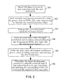
- FIG. 3 is a detailed flow chart showing SYNC_DL signals simultaneously received by a subscriber terminal from several effective base stations with the same frequency and arriving time from respective main path determined in step 201 shown in FIG. 2.
- the first step determine the SYNC_DL signals simultaneously received by a subscriber terminal from several effective base stations with the same frequency and the respective arriving time of their main path.
- FIG. 3 illustrates the detailed flow chart in step 201.
- step 301 after the synchronization of DwPTS in a subscriber terminal, 128 chips of data r are read beginning with the start of DwPTS, where the kth element is denoted as r k , k-0, 1, ..., 127.
- step 302 shift complex correlation with the data r received at DwPTS to 32 groups of local SYNC_DL codes respectively, shifting from 0 to 63, i.e., calculate the correlation power values of each point.
- step 303 the correlated power values for K frames are averaged (K ⁇ 1).
- the signal powers for two successive frames arrived at a subscriber terminal may be different because of fading, etc,.
- step 304 averaged correlation power values corresponding to SYNC_DL codes of each group in 32 groups are fined out; the arriving time for the SYNC_DL signals corresponding to the SYNC_DL codes are determined by the SYNC_DL codes, i.e., the arriving time for the main path of the SYNC_DL signals corresponding to the SYNC_DL codes; and, shift complex correlation with data r to the SYNC_DL codes to obtain the peak value of correlation power, which indicates the synchronization of received signals and the corresponding SYNC_DL codes.
- N max is a predefined value, and represents the max number of base stations in which a subscriber terminal receives the SYNC_DL signals from different base stations simultaneously.
- step 306 since a subscriber terminal is not able to know how many SYNC_DL signals are received simultaneously from base stations when it receives SYNC_DL signals, thus it is needed to determine the number N of effective base stations from which the SYNC_DL signals have been received simultaneously, based on a threshold, set the threshold V T , and firstly decide whether the N max th peak value of the averaged correlation power meets following condition: P max ( 1 ) P max ( N max ) > V T
- N N max ; otherwise, continue to decide whether the (N max -1)th peak value of the averaged correlation power values meets following condition: P max ( 1 ) P max ( N max ⁇ 1 ) > V T
- N N max -1; otherwise, the rest may be deduced by analogy, until the number N of effective base stations, from which a subscriber terminal receives the SYNC_DL signals simultaneously, is determined, where 1 ⁇ N ⁇ N max .
- the SYNC_DL codes sequence number and the peak values point corresponding to each of the N base stations are recorded as Sync_ID n and Peak n respectively, where n 1, 2, ..., N.
- the second step in step 202, combine multipath signals of SYNC_DL received from each effective base station respectively.
- the physical meaning of the formula is to perform Max Ratio Combining of multi-path SYNC_DL signals with different time delay after eliminating the phase differences both between the symbols and between the time delay paths, in which, received signals e multiplied by the conjugate of s n corresponds to eliminating the phase difference between symbols, and multiplied by the conjugate of cor n corresponds to eliminating the phase difference between time delay paths.
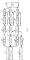
- step 202 of multi-path combining SYNC_DL signals received from a subscriber terminal will be further described with reference to FIG. 4, as shown in FIG.4.
- step 406 conjugating operation of each element of the sequence s(k) is performed, and a sequence s*(k) is obtained.
- step 408 all elements of the sequence obtained in step 407 are summed up and then conjugated.
- M 4.
- step 203 multi-path combined SYNC_DL signals of each base station are further combined.
- combining the multi-path combined SYNC_DL signals of each effective base station is to combine the calculation results of the SYNC_DL codes, and equal gain combination is used:
- step 204 rough estimation values of carrier frequency offset are calculated by using the combined signals.
- T C is an pulse width of each chip
- angle (x) is an operation of the phase angle of complex x.
- ⁇ f ⁇ is rough estimated value of the carrier frequency offset
- T C is pulse width of each chip
- angle (x) presents the operation of the phase angle of complex x.
- P and L will meet formula: P+L ⁇ 64, and P ⁇ 1, L ⁇ 1.
- the above formula indicates to firstly sum up the phase differences between two symbols spaced L, and then calculate phase angles to estimate the carrier frequency offset.
- the invention also provides an device for estimating carrier frequency offset in a subscriber terminal, which corresponding to the steps shown in FIG.2, comprising a decision module for determining number of base stations, from which the subscriber terminal receives SYNC_DL signal, based on the SYNC_DL signal received by the subscriber terminal and the main path positions of the SYNC_DL signals from each base station, and then outputting the number of effective base stations and the main path position of each signal to an combinting module; an combining module for multi-path combining the SYNC_DL signal from each effective base station based on the main path position of a signal , and then combining the multi-path combined SYNC_DL signal of each effective base station.
- the number of SYNC_DL signal in each effective base station to be combined is the number of effective base stations determined in the decision module, and then outputting the combined SYNC_DL signal to a frequency offset acquiring module; and a frequency offset acquiring module for estimating carrier frequency offset of the subscriber terminal according to the combined SYNC signals received.
- the device may further comprises a multi-path combining module for multi-path combining the signals from each effective base station and outputting the multi-path combined signal to the combining module.
- FIG.5 shows the simulation outcome of the embodiment of the invention.
- the subscriber terminal receives simultaneously the SYNC_DL signal from 3 base stations having same frequency, and the relative power received from three base stations are 0dB, -0.5dB and -1dB respectively, with corresponding SNR of 3dB, 2.5dB and 2dB.
- the deviation of a carrier frequency from a nominal frequency of these 3 base stations are uniformly distributed within (-100Hz, 100Hz).
- the relative path time delays of the three SYNC signals received by the subscriber terminal are distributed uniformly within 0-4 chips, with time delay resolution of 1/8 chip.
- the initial carrier frequency offset of UE is distributed uniformly within (-10kHz, 10kHz).
- the channel condition is an additive white Gaussian noise (AWGN) channel.
- AWGN additive white Gaussian noise
Landscapes
- Engineering & Computer Science (AREA)
- Computer Networks & Wireless Communication (AREA)
- Signal Processing (AREA)
- Mobile Radio Communication Systems (AREA)
- Circuits Of Receivers In General (AREA)
Abstract
Description
- The present invention relates to Code Division Multiple Access (CDMA) for mobile communications, more particularly to a method and device for estimating carrier frequency offset (CFO) in subscriber terminals in Time Division Synchronous Code Division Multiple Access (TD-SCDMA) system.
- In the TD-SCDMA system, both base stations and terminals are supposed to send and receive data with nominal carrier frequency. However, there is always some deviation between the actual transmitting and receiving frequency and the nominal frequency because of the technology limitation of the devices. In a base station, the frequency accuracy of an oscillator, in which a carrier frequency offset in a base station required by a TD-SCDMA system is less than 0.05PPM, may meet to the standard requirement, since limitations subjected by a base station from temperature, size, power consumption, cost and the like are smaller. In a subscriber terminal, however, a carrier frequency offset in a subscriber terminal required by the TD-SCDMA system is less than 0.1PPM, the frequency accuracy of a selected oscillator may not meet the standard requirement, due to the limitations subjected by the subscriber terminal from temperature, size, power consumption, cost and the like are greater. Consequently, carrier frequency offsets need to be estimated in a subscriber terminal by using a known synchronous downlink pilot signal (SYNC_DL) sent by base stations, and according to the estimated value of carrier frequency offsets to perform automatic frequency control (AFC), so that carrier frequency offsets in the subscriber terminal may meet the standard system requirements.
- In a method for estimating carrier frequency offset in prior art, SYNC_DL signals only send by a single base station are utilized in a subscriber terminal to estimate the carrier frequency offset. The base station has one or more antennas to transmit signals with the same carrier frequency. FIG. 1 is a schematic diagram showing a carrier frequency offset estimation system having a plurality of base stations in the prior art.
- In the TD-SCDMA system, a dedicated downlink pilot time slot (DwPTS) is set, a base station sends SYNC_DL signals at DwPTS of each frame. Codes by which a SYNC_DL signal is consisted of are used to distinguish adjacent cells using the same carrier frequency, that is, the adjacent cells with the same carrier frequency are distinguished by the SYNC_DL codes. There are 32 different SYNC_DL codes defined in the standard, length of each set of SYNC_DL codes is 64 chips. During the initial search of the cells, the subscriber terminal search the SYNC_DL codes at a specific frequency point used in a cell where it currently expects to resided in to implement the downlink synchronization, and then estimate the carrier frequency offset based on the SYNC_DL codes and adjust the carrier frequency according to the estimated carrier frequency offset value to meet the system requirements.
- Provided that the system requires for carrier frequency offset estimation and rough adjusting, adjusted carrier frequency offset in a subscriber terminal is less than 1 kHz, then the subscriber terminal has only received, at a corresponding frequency point, the SYNC_DL signals transmitted by one base station or received SYNC_DL signals of the cell currently expected to resided in are much greater than the SYNC_DL signals of other cells using a same frequency. If the signal power ratio is over 6dB, it is possible for the adjusted carrier frequency offset of a subscriber terminal to meet to the system requirement. However, if the power difference between the simultaneously received SYNC_DL signals respectively in two cells with the same frequency is small, the SYNC_DL signals transmitted by one cell will interfere those transmitted by another cell. For example, when the power ratios of multiple SYNC_DL signals received by a subscriber terminal at the edge of several cells are within 3dB, there is about 10-20% probability with the existing methods for carrier frequency offset estimation and adjustment that the carrier frequency offset of the subscriber terminal can't meet the requirement of the system.
- In the TD-SCDMA system, because of the short length of a SYNC_DL signal, which is only 64 chips (50µs), the carrier frequency offset after adjustment permitted by the standard is still greater, for example, less than 1kHz. Even so, as shown in FIG 1, when the subscriber terminal simultaneously receives SYNC_DL signals from several base stations, and whose power differences are small such as within 3dB by using an existing method for carrier frequency offset estimation, which only uses the received SYNC_DL signal in a cell (base station) where it currently expects to reside in, i.e., the highest power SYNC_DL signal, to make a carrier frequency offset estimation, there is about 10-20% probability that the carrier frequency offset in the subscriber terminal after automatic frequency control can't be below 1kHz. In this case, the initiate search for a cell by a subscriber terminal will not be implemented and probability of success for the initiate search for a cell will be affected.
- In view of this, an object of the present invention is to provide a method and a device for estimating carrier frequency offset in a subscriber terminal to make the carrier frequency offset in a subscriber terminal to meet the system requirements and thus improve the probability of success for the initiate search for a cell.
- To achieve the above object, the present invention provides a method for estimating carrier frequency offset in a subscriber terminal, said method comprises steps:
- A. determining number of effective base stations from which more than one signals are received by a subscriber terminal and main path positions of each signal;
- B. combining the signals of each station corresponding to said number of effective base stations based on the main path positions obtained in step A;
- C. calculating a rough estimation value of the carrier frequency offset based on combined signal in step B.
- Said determining number of effective base stations from which more than one signals are received by a subscriber terminal in step A comprises steps:
- A1. calculating peak power value of each signal received by a subscriber terminal, and selecting the peak power values of number of base stations from higher to lower;
- A2. determining the number of effective base stations from predefined signals are received by the subscriber terminal by comparing the ratio of the highest peak power value from the order in step A1 to the subsequent peak power values with the given threshold.
- Said signals are synchronous downlink pilot signals, and said step A1 further comprises steps:
- A11. shift multiple correlating a local synchronous downlink pilot code and a received synchronous downlink pilot signal results in a power value of the synchronous downlink pilot signals received by the subscriber terminal ;
- A12. determining peak power values corresponding to each of the synchronous downlink pilot codes.
- Said step A2 further comprises steps:
- A21. numbering the peak power values ordered from the highest to the lowest and setting a current sequence number as predefined number of the base stations;
- A22. determining whether the highest peak power value and a peak power value corresponding to the current sequence number are greater than the given threshold, if so, setting the number of effective base stations from which the signals are received by a subscriber terminal as the value of the current sequence number, otherwise, the current sequence number decreases by one and returns back to step A22.
- The method further comprises a step before said step A: reading vector data of 128 chips while receiving synchronous downlink pilot signals at the beginning of a downlink pilot time slot.
- The method further comprises a step before said step B: multi-path combining signals of each base station.
- Said step of multi-path combining signals of each base station comprises steps:
- beginning from a point of previously predetermined number of the peak power value, reading data of synchronous downlink pilot signals at a point which is 2 times of the predetermined value added length of said synchronous downlink pilot code;
- performing Max Ratio Combination after eliminating phase difference between symbols of multi-path synchronous downlink pilot signal with different time delay and the phase difference of delay path.
- Said step B of combining the signals of each station corresponding to the number of effective base stations is: equal gain combining or weight combining signals of each base station corresponding to said effective base station number to obtain an combined signal sequence.
- Said step C is to obtain a rough estimating value of the carrier frequency offset according to the phase difference between two symbols spaced by a defined distant in said combined signal sequence.
- Said step C further comprises: estimating carrier frequency offset for a predefined times, and then averaging them to get a carrier frequency offset estimation.
- Said step C is to sum up the phase differences between two symbols spaced by a defined distant in said combined signal sequence, and then computing the phase angle to get the carrier frequency offset estimation.
- The invention also provides a device for estimating carrier frequency offset, which comprises at least:
- a decision module for determining effective base station number from which signals are received by a subscriber terminal and a main path position of signal transmitted from each base station based on the signals received by a subscriber terminal, and then outputting the number of the effective base station and the main path position of each signal to an combining module;
- an combining module for combining the signals from each base station corresponding to the number of effective base stations based on the main path position of signals and then outputting the combined signals to a carrier frequency offset acquiring module;
- a carrier frequency offset acquiring module for obtaining a rough estimating value of the carrier frequency offset based on the combined signals.
- Said device further comprises a multi-path combining module for multi-path combining the signals of each base station, and then outputting the multi-path combined signal to the combining module, if the base station number is greater than 1
- According to a solution of the invention, when a subscriber terminal simultaneously receives SYNC_DL signals sent by a plurality of base stations (more than one) and their power differences are small, it is possible to make the carrier frequency offset in a subscriber terminal, after automatic frequency control, to meet the system requirement and thus improve the probability of success for the initiate search for a cell.
- The method for estimating carrier frequency offset provided by the invention is especially suitable to a condition that the strengths and SIR of SYNC_DL signals received by a mobile user from several base stations are approximate among them, i.e., a mobile user is located at the joint edge of several cells, and with the method for carrier frequency offset estimation provided by the invention, the probability of success for the initiate search for a cell can be improved greatly. Even when the SYNC_DL signal received by a mobile user from one base station is much stronger and those received from other base stations are not so strong, the accuracy of adjustment for carrier frequency offset also can be improved by using the method for estimating carrier frequency offset provided by the invention. With respect to a method utilizing the SYNC_DL signals from one base station, the closer of the SYNC_DL signal strength and SIR from several base stations, the more improvement the accuracy of carrier frequency offset adjustment.
-
- FIG. 1 shows a schematic diagram of a prior art system having several base stations for estimating carrier frequency offset;
- FIG. 2 shows a flow chart for estimating carrier frequency offset in a subscriber terminal according to the invention;
- FIG. 3 is a detailed flow chart showing the determination of the SYNC_DL signals simultaneously received by a subscriber terminal from several base stations with the same frequency and the arriving time from its main path in the steps as shown in FIG. 2;
- FIG. 4 is a flow chart principally showing the multi-path combination of the SYNC_DL signals received from one base station;
- FIG.5 shows the simulation outcome according to an embodiment of the invention.
- Hereinafter, detailed description will be made to a method and device for estimating carrier frequency offset in a subscriber terminal in TD-SCDMA system according to the embodiments of the invention, with reference to accompanying drawings, so that the invention will be well understood by those skilled in the art.
- FIG. 2 shows a flow chart for estimating carrier frequency offset in a subscriber terminal according to the invention, and FIG. 3 is a detailed flow chart showing SYNC_DL signals simultaneously received by a subscriber terminal from several effective base stations with the same frequency and arriving time from respective main path determined in
step 201 shown in FIG. 2. - The first step, in
step 201, determine the SYNC_DL signals simultaneously received by a subscriber terminal from several effective base stations with the same frequency and the respective arriving time of their main path. - FIG. 3 illustrates the detailed flow chart in
step 201. Instep 301, after the synchronization of DwPTS in a subscriber terminal, 128 chips of data r are read beginning with the start of DwPTS, where the kth element is denoted as rk , k-0, 1, ..., 127. - Then, in
step 302, shift complex correlation with the data r received at DwPTS to 32 groups of local SYNC_DL codes respectively, shifting from 0 to 63, i.e., calculate the correlation power values of each point. - In
step 303, the correlated power values for K frames are averaged (K≥1). - The signal powers for two successive frames arrived at a subscriber terminal may be different because of fading, etc,. To ensure the accuracy of the data obtained in a subscriber terminal, it is preferable to calculate the correlation power by using more frames of data and then average them.
- Then, in
step 304, averaged correlation power values corresponding to SYNC_DL codes of each group in 32 groups are fined out; the arriving time for the SYNC_DL signals corresponding to the SYNC_DL codes are determined by the SYNC_DL codes, i.e., the arriving time for the main path of the SYNC_DL signals corresponding to the SYNC_DL codes; and, shift complex correlation with data r to the SYNC_DL codes to obtain the peak value of correlation power, which indicates the synchronization of received signals and the corresponding SYNC_DL codes. - In
step 305, the peak values of the averaged correlation power are ordered in a falling sequence, and the first Nmax ones are selected, denoted as Pmax (n) , n=1, 2, ..., Nmax. Nmax is a predefined value, and represents the max number of base stations in which a subscriber terminal receives the SYNC_DL signals from different base stations simultaneously. - In
step 306, since a subscriber terminal is not able to know how many SYNC_DL signals are received simultaneously from base stations when it receives SYNC_DL signals, thus it is needed to determine the number N of effective base stations from which the SYNC_DL signals have been received simultaneously, based on a threshold, set the threshold VT, and firstly decide whether the Nmax th peak value of the averaged correlation power meets following condition:
- If yes, N = Nmax; otherwise, continue to decide whether the (Nmax -1)th peak value of the averaged correlation power values meets following condition:

- If yes, N = Nmax -1; otherwise, the rest may be deduced by analogy, until the number N of effective base stations, from which a subscriber terminal receives the SYNC_DL signals simultaneously, is determined, where 1 ≤ N ≤ Nmax. The SYNC_DL codes sequence number and the peak values point corresponding to each of the N base stations are recorded as Sync_IDn and Peakn respectively, where n=1, 2, ..., N.
- In the embodiment of the invention, Nmax=3, and VT=4.
- The second step, in
step 202, combine multipath signals of SYNC_DL received from each effective base station respectively. - Then, the complex SYNC_DL codes numbered as Sync_IDn are operated, and the complex values of SYNC_DL codes are marked as sn , where the kth element is sn,k , k=0, 1, ..., 63. 64+2M points of data are read beginning from M chips ahead of Peakn in the DwPTS of the received signals, marked as a vector e, where the kth element is ek, k=1, 2, ..., 63+2M.
- e is shift complex correlated with s n , and the result cor n is obtained:


- The physical meaning of the formula is to perform Max Ratio Combining of multi-path SYNC_DL signals with different time delay after eliminating the phase differences both between the symbols and between the time delay paths, in which, received signals e multiplied by the conjugate of s n corresponds to eliminating the phase difference between symbols, and multiplied by the conjugate of cor n corresponds to eliminating the phase difference between time delay paths.
- The process of
step 202 of multi-path combining SYNC_DL signals received from a subscriber terminal will be further described with reference to FIG. 4, as shown in FIG.4. - In
step 401, 64+2M points of data are read beginning from M chips ahead of Peakn in the SYNC_DL signals received at DwPTS, i.e., 64+2M received data is read beginning from M chips ahead of the position of the main path, and a complex sequence of 64+2M is obtained, e(k), k=0, 1, ..., 63+2M, marked as a vector e , where 64 is the length of the SYNC_DL code. - In
step 402, the SYNC_DL codes numbered SYNC_ID are complex operated and the complex SYNC_DL codes are obtained, i.e., the local complex SYNC_DL code sequence s(k), k=0, 1, ..., 63, marked as s n o - Then, in
step 406, conjugating operation of each element of the sequence s(k) is performed, and a sequence s*(k) is obtained. - Because e(k+1) includes a phase shift, in order to eliminate the phase shift between subsequent two phases, in
step 403, letd(0,k) = e(k), k=0, 1, ..., 63; instep 404, let d(1,k)=e(k+1), k=0, 1, ..., 63, ..., and instep 405, let d(2M, k) = e(k + 2M), k=0, 1, ..., 63. - In
step 407, each element of the sequence d(i, k) (i = 0,1,···,2M , k=0, 1, ..., 63) obtained in steps 403-405 is multiplied by the corresponding element of the sequence s*(k) obtained instep 406 respectively. - In
step 408, all elements of the sequence obtained instep 407 are summed up and then conjugated. In steps 403 -step 408, shift multiplex correlation of e and

- In
step 409, the result of shift multiplex correlation is multiplied by all elements of the sequence, then, instep 410, all 2M+1 sequences, i.e., multi-path combining the SYNC_DL signal of each path, are summed up and a vector Un is calculated as follows:
- The value of M is integrally dependent on both the time delay extension of the received signals and the effect of noise. In the embodiment of the invention, M = 4.
- The third step, in
step 203, multi-path combined SYNC_DL signals of each base station are further combined.
combining the multi-path combined SYNC_DL signals of each effective base station is to combine the calculation results of the SYNC_DL codes, and equal gain combination is used:


- Because there is coherent property among the SYNC_DL signals from each effective base station while noncoherent property among noises, it is possible to improve the SNR (or SIR) of available signals by combining the multi-path combined SYNC_DL signals from each effective base station so that the SYNC_DL signals received by a subscriber terminal may be efficiently utilized.
- Based on theory formula, the sequence combined by the SYNC_DL signals from each effective base station can be approximately represented as follows:

Ak is magnitude of combined SYNC_DL signals valid in the kth symbol;
exp(x) indicates exponent operation of complex x;
Δf is carrier frequency offset, which is the exact value in theory;
Tc is pulse width of each chip;
φ0 is initial phase of the SYNC_DL signals received by a subscriber terminal, range of which is between 0 ~ 2π ;
Nk is the complex noise value or interference noise value in the kth symbol o - The fourth step, in
step 204, rough estimation values of carrier frequency offset are calculated by using the combined signals. - Based on the theoretical formula in
step 203, it can be seen from the expression of Uk that in the combined SYNC_DL signal sequence, a variation rate of phase between symbols is associated with a carrier frequency offset Δf . Therefore, a carrier frequency offset can be roughly estimated by using the combined SYNC_DL signal sequence. In one embodiment of the invention,
- Where Δf̂ is a rough estimation of the carrier frequency offset, TC is an pulse width of each chip, and angle (x) is an operation of the phase angle of complex x. Values P and L will meet formula: P+L≤64, and P≥1, L≥1.
- Above formula indicates the effect of noise (or interference) can be minimized by using a phase difference between two symbols spaced by L to estimate the carrier frequency offset, and then averaging the estimated values for P times.
- In another embodiment of the invention,

- Where Δf̂ is rough estimated value of the carrier frequency offset, TC is pulse width of each chip, and angle (x) presents the operation of the phase angle of complex x. Values P and L will meet formula: P+L≤64, and P≥1, L≥1.
- In order to minimize calculating amount of repeatedly calculating phase angle, the above formula indicates to firstly sum up the phase differences between two symbols spaced L, and then calculate phase angles to estimate the carrier frequency offset.
- Due to the phases of two consecutive symbols are close together, an angle jitter of the multiplied phase angle will be greater. Therefore, it is preferable to multiply two symbols spaced L to avoid the angle jitter to be more great.
- In the embodiment of the invention, P = L = 32o
- The invention also provides an device for estimating carrier frequency offset in a subscriber terminal, which corresponding to the steps shown in FIG.2, comprising a decision module for determining number of base stations, from which the subscriber terminal receives SYNC_DL signal, based on the SYNC_DL signal received by the subscriber terminal and the main path positions of the SYNC_DL signals from each base station, and then outputting the number of effective base stations and the main path position of each signal to an combinting module; an combining module for multi-path combining the SYNC_DL signal from each effective base station based on the main path position of a signal , and then combining the multi-path combined SYNC_DL signal of each effective base station. The number of SYNC_DL signal in each effective base station to be combined is the number of effective base stations determined in the decision module, and then outputting the combined SYNC_DL signal to a frequency offset acquiring module; and a frequency offset acquiring module for estimating carrier frequency offset of the subscriber terminal according to the combined SYNC signals received. The device may further comprises a multi-path combining module for multi-path combining the signals from each effective base station and outputting the multi-path combined signal to the combining module.
- FIG.5 shows the simulation outcome of the embodiment of the invention. In this simulation, we assume that the subscriber terminal (UE) receives simultaneously the SYNC_DL signal from 3 base stations having same frequency, and the relative power received from three base stations are 0dB, -0.5dB and -1dB respectively, with corresponding SNR of 3dB, 2.5dB and 2dB. The deviation of a carrier frequency from a nominal frequency of these 3 base stations are uniformly distributed within (-100Hz, 100Hz). The relative path time delays of the three SYNC signals received by the subscriber terminal are distributed uniformly within 0-4 chips, with time delay resolution of 1/8 chip. The initial carrier frequency offset of UE is distributed uniformly within (-10kHz, 10kHz). The channel condition is an additive white Gaussian noise (AWGN) channel.
- UE carrier frequency offset is roughly adjusted by using the method provided by the invention. Parameters are selected as follows: K=4, VT=4, M=4. The simulation outcome is shown in Figure 5. Nmax=1 indicates that the carrier frequency offset is estimated by using the SYNC signal from one base station, Nmax=2 indicates that the carrier frequency offset is estimated by using the SYNC signal from two base stations, at most, having same frequency, and Nmax=3 indicates that the carrier frequency offset is estimated by using the SYNC signal from three base stations, at most, having a same frequency. It can be seen from FIG.5, when UE simultaneously receives the SYNC signals from 3 base stations having same frequency and transmission powers from each base station is not much different from each other, if the carrier frequency offset is estimated by using the SYNC signal only from one base station (Nmax=1), then there is still about 27% of carrier frequency offset to be over 1kHz after AFC. But if the carrier frequency offset is estimated by using the SYNC signal from three base stations having same frequency, it is possible to keep the carrier frequency offset under 1kHz and the adjustment accuracy thereof will be increased greatly.
- In summery, the description above is only the preferred embodiments of the invention but will not limit the protection scope of the invention.
Claims (14)
- A method for estimating carrier frequency offset in subscriber terminals, said method comprises steps:A. determining number of effective base stations from which more than one signals are received by a subscriber terminal and main path positions of each signal;B. combining the signals of each station corresponding to said number of effective base stations based on the main path positions obtained in step A;C. calculating a rough estimation value of the carrier frequency offset based on combined signal in step B.
- A method as claimed in claim 1, wherein said determining number of effective base stations from which more than one signals are received by a subscriber terminal in step A comprises steps:A1. calculating peak power value of each signal received by a subscriber terminal, and selecting the peak power values of predefined number of base stations from higher to lower;A2. determining the number of effective base stations from predefined number of signals are received by the subscriber terminal by comparing the ratio of the highest peak power value from the order in step A1 to the subsequent peak power values with the given threshold.
- A method as claimed in claim 2, wherein said signals are synchronous downlink pilot signals, and said step A1 further comprises steps:A11. shift multiple correlating a local synchronous downlink pilot code and a received synchronous downlink pilot signal results in a power value of the synchronous downlink pilot signals received by the subscriber terminal ;A12. determining peak power values corresponding to each of the synchronous downlink pilot codes.
- A method as claimed in claim 3, wherein said method further comprises steps in between step A11 and step A12: selecting the power values of each frame of more than one frames and averaging said power values of each frame.
- A method as claimed in claim 2, wherein said step A2 further comprises steps:A21. numbering the peak power values ordered from the highest to the lowest and setting a current sequence number as predefined number of the base stations;A22. determining whether the highest peak power value and a peak power value corresponding to the current sequence number are greater than the given threshold, if so, setting the number of effective base stations from which the signals are received by a subscriber terminal as the value of the current sequence number, otherwise, the current sequence number decreases by one and returns back to step A22.
- A method as claimed in claim 1, further comprises a step before said step A: reading vector data of 128 chips while receiving synchronous downlink pilot signals at the beginning of a downlink pilot time slot.
- A method as claimed in claim 2, further comprises a step before said step B: multi-path combining signals of each base station.
- A method as claimed in claim 7, wherein said step of multi-path combining signals of each base station comprises steps:beginning from a point of previously predetermined number of the peak power value, reading data of synchronous downlink pilot signals at a point which is 2 times of the predetermined value added length of said synchronous downlink pilot code;performing Max Ratio Combination after eliminating phase difference between symbols of multi-path synchronous downlink pilot signal with different time delay and the phase difference of delay path.
- A method as claimed in claim 1, wherein said step B of incorporating the signals of each station corresponding to the number of base stations is:to equal gain combining or weighting combining signals of each base station corresponding to said base station number to obtain an combined signal sequence.
- A method as claimed in claim 9, wherein said step C is to obtain a rough estimating value of the carrier frequency offset according to the phase difference between two symbols spaced by a defined distant in said combined signal sequence.
- A method as claimed in claim 10, wherein said step C further comprises: estimating carrier frequency offset for a predefined times, and then averaging them to get a carrier frequency offset estimation.
- A method as claimed in claim 10, wherein said step C is to sum up the phase differences between two symbols spaced by a defined distant in said incorporated signal sequence, and then computing the phase angle to get the carrier frequency offset estimation.
- A device for estimating carrier frequency offset, said device comprises at least:a decision module for determining base station number from which signals are received by a subscriber terminal and a main path position of signal transmitted from each base station based on the signals received by a subscriber terminal, and then outputting the number of the effective base station and the main path position of each signal to an combining module;a combinting module for combining the signals from each base station corresponding to the number of effective base stations based on the main path position of signals and then outputting the combined signals to a carrier frequency offset acquiring module;a carrier frequency offset acquiring module for obtaining a rough estimating value of the carrier frequency offset based on the combined signals.
- A device as claimed in claim 13, wherein said device further comprises a multi-path combining module for multi-path combining the signals of each base station, and then outputting the multi-path combined signal to the combining module, if the effective base station number is greater than 1.
Applications Claiming Priority (2)
| Application Number | Priority Date | Filing Date | Title |
|---|---|---|---|
| CNB031496199A CN1259785C (en) | 2003-08-04 | 2003-08-04 | Method for obtaining carrier frequency departure of time division synchronous CDMA (TD-SCDMA) user terminal and equipment |
| PCT/CN2004/000898 WO2005013524A1 (en) | 2003-08-04 | 2004-08-04 | A method and device of the estimating carrier frequency offset of subscriber terminal |
Publications (3)
| Publication Number | Publication Date |
|---|---|
| EP1653645A1 true EP1653645A1 (en) | 2006-05-03 |
| EP1653645A4 EP1653645A4 (en) | 2011-09-14 |
| EP1653645B1 EP1653645B1 (en) | 2018-10-17 |
Family
ID=31723314
Family Applications (1)
| Application Number | Title | Priority Date | Filing Date |
|---|---|---|---|
| EP04762035.6A Expired - Lifetime EP1653645B1 (en) | 2003-08-04 | 2004-08-04 | A method and device of the estimating carrier frequency offset of subscriber terminal |
Country Status (6)
| Country | Link |
|---|---|
| US (1) | US7672277B2 (en) |
| EP (1) | EP1653645B1 (en) |
| JP (1) | JP4340290B2 (en) |
| KR (1) | KR100711842B1 (en) |
| CN (1) | CN1259785C (en) |
| WO (1) | WO2005013524A1 (en) |
Cited By (3)
| Publication number | Priority date | Publication date | Assignee | Title |
|---|---|---|---|---|
| CN100459764C (en) * | 2006-08-08 | 2009-02-04 | 北京天碁科技有限公司 | Method and system for frequency offset estimation and frequency offset adjustment of mobile terminal |
| EP2306771A4 (en) * | 2008-07-17 | 2014-07-09 | Zte Corp | METHOD FOR MEASURING ADJACENT AREAS |
| CN112019466A (en) * | 2020-08-31 | 2020-12-01 | 成都链讯信息技术有限公司 | Frequency estimation method of front and back synchronous code combined pilot frequency |
Families Citing this family (31)
| Publication number | Priority date | Publication date | Assignee | Title |
|---|---|---|---|---|
| CN100362894C (en) * | 2004-07-13 | 2008-01-16 | 中兴通讯股份有限公司 | Method for carrier frequency resource configuration and carrier frequency resource state information reporting |
| WO2006005238A1 (en) * | 2004-07-13 | 2006-01-19 | Zte Corporation | A method for reporting the frequency resource arrangement and frequency information of the multi-frequency cell |
| CN100352183C (en) * | 2004-08-14 | 2007-11-28 | 华为技术有限公司 | channel establishment method |
| CN100421365C (en) * | 2004-08-14 | 2008-09-24 | 华为技术有限公司 | Method for implementing radio resource control of user equipment |
| CN1798118A (en) * | 2004-12-24 | 2006-07-05 | 展讯通信(上海)有限公司 | Method for estimating frequency deviation accurately in TD-SCDMA |
| CN1841966A (en) * | 2005-04-01 | 2006-10-04 | 展讯通信(上海)有限公司 | Downlink synchronization code modulation phase sequence judging method in cell search |
| CN1917411B (en) * | 2005-08-16 | 2012-03-07 | 中兴通讯股份有限公司 | System and method for realization of accessing high speed down going packets in multiple carriers |
| US8588126B2 (en) * | 2006-11-08 | 2013-11-19 | Trellisware Technologies, Inc. | Methods and apparatus for network communication via barrage relay onto an independent medium allocation |
| US8457005B2 (en) | 2006-11-08 | 2013-06-04 | Trellisware Technologies, Inc. | Method and system for establishing cooperative routing in wireless networks |
| CN101026408B (en) * | 2007-01-19 | 2011-10-05 | 重庆重邮信科通信技术有限公司 | Frequency fine correction method and device for time division-synchronous CDMA system |
| JP5015245B2 (en) * | 2007-04-27 | 2012-08-29 | パナソニック株式会社 | Signal determination apparatus and signal determination method |
| US7899136B2 (en) * | 2007-05-03 | 2011-03-01 | Infineon Technologies Ag | Frequency-offset estimation |
| US9054822B2 (en) | 2007-08-02 | 2015-06-09 | Trellisware Technologies, Inc. | Method and system for synchronization of time-slotted barrage relay networks |
| US8576946B2 (en) * | 2007-10-19 | 2013-11-05 | Trellisware Technologies, Inc. | Method and system for cooperative communications with minimal coordination |
| ES2370848T3 (en) * | 2007-11-29 | 2011-12-23 | Telefonaktiebolaget Lm Ericsson (Publ) | CELL SEARCH METHOD FOR A MULTIMODE TELECOMMUNICATION DEVICE, SUCH APPARATUS, AND COMPUTER PROGRAM TO IMPLEMENT THE METHOD. |
| KR20110026479A (en) * | 2008-07-07 | 2011-03-15 | 스미토모덴키고교가부시키가이샤 | Base station device |
| US9398502B2 (en) | 2008-07-17 | 2016-07-19 | Zte Corporation | Method for measuring adjacent areas |
| CN101674103A (en) * | 2008-07-18 | 2010-03-17 | 俊茂微电子(上海)有限公司 | An automatic-frequency correction equipment, method and radio communication device |
| US20100304679A1 (en) * | 2009-05-28 | 2010-12-02 | Hanks Zeng | Method and System For Echo Estimation and Cancellation |
| JP2011003970A (en) * | 2009-06-16 | 2011-01-06 | Fujitsu Ltd | Receiving apparatus, base station apparatus, and synchronization timing detection method |
| CN101997800B (en) * | 2009-08-14 | 2015-04-01 | 展讯通信(上海)有限公司 | Method and device for estimating carrier frequency offset |
| US9401784B2 (en) | 2009-10-21 | 2016-07-26 | Qualcomm Incorporated | Time and frequency acquisition and tracking for OFDMA wireless systems |
| US10111111B2 (en) * | 2009-11-19 | 2018-10-23 | Qualcomm Incorporated | Per-cell timing and/or frequency acquisition and their use on channel estimation in wireless networks |
| CN102082743B (en) * | 2009-11-27 | 2013-04-10 | 重庆重邮信科通信技术有限公司 | Automatic frequency calibration method and device of time division-synchronization code division multiple access (TD-SCDMA) system |
| CN101808061B (en) * | 2010-03-12 | 2014-03-19 | 中兴通讯股份有限公司 | Frequency offset estimation method and device |
| CN101977071A (en) * | 2010-10-25 | 2011-02-16 | 北京交通大学 | Multi-receiving-antenna frequency offset estimation method used for orthogonal frequency division multiplexing |
| US8548033B2 (en) * | 2010-12-23 | 2013-10-01 | Microchip Technology Incorporated | Automatic frequency control under low signal-to-noise conditions |
| CN103841609B (en) * | 2012-11-27 | 2018-09-11 | 中兴通讯股份有限公司 | Downlink synchronization tracking method and device when TD-SCDMA switches |
| TWI548294B (en) * | 2014-03-10 | 2016-09-01 | 鴻海精密工業股份有限公司 | Femtocell and method of adusting frequency |
| US11187773B2 (en) * | 2016-11-04 | 2021-11-30 | Telefonaktiebolaget Lm Ericsson (Publ) | Positioning support information for time of arrival (TOA) estimation in possible multipath propagation conditions |
| CN121126511B (en) * | 2025-11-12 | 2026-03-03 | 广东世炬网络科技股份有限公司 | An air interface synchronization method, apparatus, device and storage medium |
Family Cites Families (15)
| Publication number | Priority date | Publication date | Assignee | Title |
|---|---|---|---|---|
| GB9405297D0 (en) * | 1994-03-17 | 1994-04-27 | Roke Manor Research | Synchronisation apparatus |
| FI102577B1 (en) | 1996-09-05 | 1998-12-31 | Nokia Telecommunications Oy | Transmission and reception procedure and radio system |
| CN1061205C (en) * | 1997-07-24 | 2001-01-24 | 北京信威通信技术有限公司 | Method for device of carrier exalting and compensating in frequency spreading communication system |
| JP2001016135A (en) * | 1999-06-29 | 2001-01-19 | Nec Corp | Method and system for automatically controlling frequency and cdma receiver |
| JP3637812B2 (en) | 1999-07-01 | 2005-04-13 | 三菱電機株式会社 | CDMA communication apparatus |
| JP3419361B2 (en) | 1999-09-29 | 2003-06-23 | 株式会社デンソー | Spread spectrum receiver |
| CN1133351C (en) | 1999-11-12 | 2003-12-31 | 深圳市中兴通讯股份有限公司 | Time slot synchronizer in regional search for WCDMA system |
| GB2359456B (en) * | 2000-02-19 | 2003-09-17 | Nec Technologies | Method for frequency offset estimation in a direct sequence spread spectrum communications receiver |
| CN1131653C (en) | 2000-03-27 | 2003-12-17 | 信息产业部电信科学技术研究院 | Small-region initial search method for CDMA digital mobile communication system |
| JP2002043978A (en) | 2000-07-28 | 2002-02-08 | Hitachi Kokusai Electric Inc | CDMA receiver |
| FR2827098B1 (en) * | 2001-07-05 | 2003-12-05 | Nortel Networks Ltd | METHOD FOR CONTROLLING RADIO RESOURCES ASSIGNED TO COMMUNICATION BETWEEN A MOBILE TERMINAL AND A SPREAD-SPECTRUM CELLULAR INFRASTRUCTURE, AND EQUIPMENT FOR IMPLEMENTING THE METHOD |
| US6760365B2 (en) * | 2001-10-11 | 2004-07-06 | Interdigital Technology Corporation | Acquisition circuit for low chip rate option for mobile telecommunication system |
| US7173992B2 (en) * | 2001-12-11 | 2007-02-06 | Sasken Communication Technologies Limited | Method for synchronization in wireless systems using receive diversity |
| JP2003309491A (en) | 2002-04-16 | 2003-10-31 | Matsushita Electric Ind Co Ltd | Communication terminal device and automatic frequency control method |
| US7269206B2 (en) * | 2003-05-13 | 2007-09-11 | Benq Corporation | Flexible correlation for cell searching in a CDMA system |
-
2003
- 2003-08-04 CN CNB031496199A patent/CN1259785C/en not_active Expired - Lifetime
-
2004
- 2004-08-04 KR KR20067002405A patent/KR100711842B1/en not_active Expired - Lifetime
- 2004-08-04 WO PCT/CN2004/000898 patent/WO2005013524A1/en not_active Ceased
- 2004-08-04 US US10/566,619 patent/US7672277B2/en not_active Expired - Lifetime
- 2004-08-04 EP EP04762035.6A patent/EP1653645B1/en not_active Expired - Lifetime
- 2004-08-04 JP JP2006522199A patent/JP4340290B2/en not_active Expired - Lifetime
Cited By (4)
| Publication number | Priority date | Publication date | Assignee | Title |
|---|---|---|---|---|
| CN100459764C (en) * | 2006-08-08 | 2009-02-04 | 北京天碁科技有限公司 | Method and system for frequency offset estimation and frequency offset adjustment of mobile terminal |
| EP2306771A4 (en) * | 2008-07-17 | 2014-07-09 | Zte Corp | METHOD FOR MEASURING ADJACENT AREAS |
| CN112019466A (en) * | 2020-08-31 | 2020-12-01 | 成都链讯信息技术有限公司 | Frequency estimation method of front and back synchronous code combined pilot frequency |
| CN112019466B (en) * | 2020-08-31 | 2022-06-10 | 成都链讯信息技术有限公司 | Frequency estimation method of front and back synchronous code combined pilot frequency |
Also Published As
| Publication number | Publication date |
|---|---|
| WO2005013524A1 (en) | 2005-02-10 |
| US20070140203A1 (en) | 2007-06-21 |
| CN1259785C (en) | 2006-06-14 |
| KR20060069833A (en) | 2006-06-22 |
| US7672277B2 (en) | 2010-03-02 |
| EP1653645A4 (en) | 2011-09-14 |
| JP2007501548A (en) | 2007-01-25 |
| JP4340290B2 (en) | 2009-10-07 |
| KR100711842B1 (en) | 2007-05-02 |
| CN1477807A (en) | 2004-02-25 |
| EP1653645B1 (en) | 2018-10-17 |
Similar Documents
| Publication | Publication Date | Title |
|---|---|---|
| US7672277B2 (en) | Method and device for estimating carrier frequency offset of subscriber terminal | |
| US8738054B2 (en) | Efficient frame tracking in mobile receivers | |
| US7209512B2 (en) | CDMA receiver, and searcher in a CDMA receiver | |
| EP1337054B1 (en) | Wireless receiver estimating power of interference | |
| US20040013169A1 (en) | Phase rotation detection apparatus and radio base station apparatus provided therewith | |
| US20010021199A1 (en) | Apparatus for searching for a cell and method of acquiring code unique to each cell in an asynchronous wideband DS/CDMA receiver | |
| US6950458B2 (en) | Method and apparatus for acquiring slot timing and frequency offset correction and storage medium storing control program therefor | |
| JP3924778B2 (en) | Frequency offset estimation method in direct spread spectrum communication receiver | |
| US6289061B1 (en) | Wideband frequency tracking system and method | |
| US7792151B2 (en) | CDMA receiving apparatus and method | |
| AU2001234091A1 (en) | Method for frequency offset estimation in a direct sequence spread spectrum communications receiver | |
| US7085311B2 (en) | Apparatus and method for measuring SIR in CDMA communication system | |
| KR20000047620A (en) | Communication terminal apparatus and radio communication method | |
| WO2000060763A1 (en) | Estimation of signal to interference ratio in a mobile communication system | |
| US20030016646A1 (en) | Channel estimating apparatus and channel estimating method | |
| US8107564B2 (en) | Device for detecting a frequency offset | |
| US7295535B2 (en) | Method for signal acquisition in a wireless terminal and wireless terminal | |
| EP1082868B1 (en) | Method of measuring signal timing, and radio system | |
| US7474610B2 (en) | OFDM automatic frequency control device and method thereof | |
| US8279982B2 (en) | Method and system for estimating the speed of a mobile device in a network | |
| JP2002084568A (en) | Cell search method for mobile station in CDMA mobile communication system, and CDMA mobile communication system | |
| CN100502249C (en) | Receiver and automatic frequency control method |
Legal Events
| Date | Code | Title | Description |
|---|---|---|---|
| PUAI | Public reference made under article 153(3) epc to a published international application that has entered the european phase |
Free format text: ORIGINAL CODE: 0009012 |
|
| 17P | Request for examination filed |
Effective date: 20060221 |
|
| AK | Designated contracting states |
Kind code of ref document: A1 Designated state(s): AT BE BG CH CY CZ DE DK EE ES FI FR GB GR HU IE IT LI LU MC NL PL PT RO SE SI SK TR |
|
| DAX | Request for extension of the european patent (deleted) | ||
| A4 | Supplementary search report drawn up and despatched |
Effective date: 20110817 |
|
| RIC1 | Information provided on ipc code assigned before grant |
Ipc: H04B 1/707 20110101ALI20110810BHEP Ipc: H04J 11/00 20060101AFI20110810BHEP |
|
| RAP1 | Party data changed (applicant data changed or rights of an application transferred) |
Owner name: CHINA ACADEMY OF TELECOMMUNICATIONS TECHNOLOGY |
|
| 17Q | First examination report despatched |
Effective date: 20120315 |
|
| GRAP | Despatch of communication of intention to grant a patent |
Free format text: ORIGINAL CODE: EPIDOSNIGR1 |
|
| STAA | Information on the status of an ep patent application or granted ep patent |
Free format text: STATUS: GRANT OF PATENT IS INTENDED |
|
| INTG | Intention to grant announced |
Effective date: 20180615 |
|
| GRAS | Grant fee paid |
Free format text: ORIGINAL CODE: EPIDOSNIGR3 |
|
| GRAA | (expected) grant |
Free format text: ORIGINAL CODE: 0009210 |
|
| STAA | Information on the status of an ep patent application or granted ep patent |
Free format text: STATUS: THE PATENT HAS BEEN GRANTED |
|
| REG | Reference to a national code |
Ref country code: DE Ref legal event code: R081 Ref document number: 602004053302 Country of ref document: DE Owner name: DATANG MOBILE COMMUNICATIONS EQUIPMENT CO., LT, CN Free format text: FORMER OWNER: DA TANG MOBILE COMMUNICATIONS EQUIPMENT CO., LTD., PEKING/BEI-JING, CN |
|
| AK | Designated contracting states |
Kind code of ref document: B1 Designated state(s): AT BE BG CH CY CZ DE DK EE ES FI FR GB GR HU IE IT LI LU MC NL PL PT RO SE SI SK TR |
|
| REG | Reference to a national code |
Ref country code: GB Ref legal event code: FG4D |
|
| REG | Reference to a national code |
Ref country code: CH Ref legal event code: EP |
|
| REG | Reference to a national code |
Ref country code: IE Ref legal event code: FG4D |
|
| REG | Reference to a national code |
Ref country code: DE Ref legal event code: R096 Ref document number: 602004053302 Country of ref document: DE Ref country code: AT Ref legal event code: REF Ref document number: 1055251 Country of ref document: AT Kind code of ref document: T Effective date: 20181115 |
|
| REG | Reference to a national code |
Ref country code: NL Ref legal event code: MP Effective date: 20181017 |
|
| REG | Reference to a national code |
Ref country code: AT Ref legal event code: MK05 Ref document number: 1055251 Country of ref document: AT Kind code of ref document: T Effective date: 20181017 |
|
| PG25 | Lapsed in a contracting state [announced via postgrant information from national office to epo] |
Ref country code: NL Free format text: LAPSE BECAUSE OF FAILURE TO SUBMIT A TRANSLATION OF THE DESCRIPTION OR TO PAY THE FEE WITHIN THE PRESCRIBED TIME-LIMIT Effective date: 20181017 |
|
| PG25 | Lapsed in a contracting state [announced via postgrant information from national office to epo] |
Ref country code: ES Free format text: LAPSE BECAUSE OF FAILURE TO SUBMIT A TRANSLATION OF THE DESCRIPTION OR TO PAY THE FEE WITHIN THE PRESCRIBED TIME-LIMIT Effective date: 20181017 Ref country code: BG Free format text: LAPSE BECAUSE OF FAILURE TO SUBMIT A TRANSLATION OF THE DESCRIPTION OR TO PAY THE FEE WITHIN THE PRESCRIBED TIME-LIMIT Effective date: 20190117 Ref country code: AT Free format text: LAPSE BECAUSE OF FAILURE TO SUBMIT A TRANSLATION OF THE DESCRIPTION OR TO PAY THE FEE WITHIN THE PRESCRIBED TIME-LIMIT Effective date: 20181017 Ref country code: PL Free format text: LAPSE BECAUSE OF FAILURE TO SUBMIT A TRANSLATION OF THE DESCRIPTION OR TO PAY THE FEE WITHIN THE PRESCRIBED TIME-LIMIT Effective date: 20181017 Ref country code: FI Free format text: LAPSE BECAUSE OF FAILURE TO SUBMIT A TRANSLATION OF THE DESCRIPTION OR TO PAY THE FEE WITHIN THE PRESCRIBED TIME-LIMIT Effective date: 20181017 |
|
| PG25 | Lapsed in a contracting state [announced via postgrant information from national office to epo] |
Ref country code: SE Free format text: LAPSE BECAUSE OF FAILURE TO SUBMIT A TRANSLATION OF THE DESCRIPTION OR TO PAY THE FEE WITHIN THE PRESCRIBED TIME-LIMIT Effective date: 20181017 Ref country code: PT Free format text: LAPSE BECAUSE OF FAILURE TO SUBMIT A TRANSLATION OF THE DESCRIPTION OR TO PAY THE FEE WITHIN THE PRESCRIBED TIME-LIMIT Effective date: 20190217 Ref country code: GR Free format text: LAPSE BECAUSE OF FAILURE TO SUBMIT A TRANSLATION OF THE DESCRIPTION OR TO PAY THE FEE WITHIN THE PRESCRIBED TIME-LIMIT Effective date: 20190118 |
|
| REG | Reference to a national code |
Ref country code: DE Ref legal event code: R097 Ref document number: 602004053302 Country of ref document: DE |
|
| PG25 | Lapsed in a contracting state [announced via postgrant information from national office to epo] |
Ref country code: IT Free format text: LAPSE BECAUSE OF FAILURE TO SUBMIT A TRANSLATION OF THE DESCRIPTION OR TO PAY THE FEE WITHIN THE PRESCRIBED TIME-LIMIT Effective date: 20181017 Ref country code: DK Free format text: LAPSE BECAUSE OF FAILURE TO SUBMIT A TRANSLATION OF THE DESCRIPTION OR TO PAY THE FEE WITHIN THE PRESCRIBED TIME-LIMIT Effective date: 20181017 Ref country code: CZ Free format text: LAPSE BECAUSE OF FAILURE TO SUBMIT A TRANSLATION OF THE DESCRIPTION OR TO PAY THE FEE WITHIN THE PRESCRIBED TIME-LIMIT Effective date: 20181017 |
|
| PLBE | No opposition filed within time limit |
Free format text: ORIGINAL CODE: 0009261 |
|
| STAA | Information on the status of an ep patent application or granted ep patent |
Free format text: STATUS: NO OPPOSITION FILED WITHIN TIME LIMIT |
|
| PG25 | Lapsed in a contracting state [announced via postgrant information from national office to epo] |
Ref country code: SK Free format text: LAPSE BECAUSE OF FAILURE TO SUBMIT A TRANSLATION OF THE DESCRIPTION OR TO PAY THE FEE WITHIN THE PRESCRIBED TIME-LIMIT Effective date: 20181017 Ref country code: EE Free format text: LAPSE BECAUSE OF FAILURE TO SUBMIT A TRANSLATION OF THE DESCRIPTION OR TO PAY THE FEE WITHIN THE PRESCRIBED TIME-LIMIT Effective date: 20181017 Ref country code: RO Free format text: LAPSE BECAUSE OF FAILURE TO SUBMIT A TRANSLATION OF THE DESCRIPTION OR TO PAY THE FEE WITHIN THE PRESCRIBED TIME-LIMIT Effective date: 20181017 |
|
| 26N | No opposition filed |
Effective date: 20190718 |
|
| PG25 | Lapsed in a contracting state [announced via postgrant information from national office to epo] |
Ref country code: SI Free format text: LAPSE BECAUSE OF FAILURE TO SUBMIT A TRANSLATION OF THE DESCRIPTION OR TO PAY THE FEE WITHIN THE PRESCRIBED TIME-LIMIT Effective date: 20181017 |
|
| PG25 | Lapsed in a contracting state [announced via postgrant information from national office to epo] |
Ref country code: TR Free format text: LAPSE BECAUSE OF FAILURE TO SUBMIT A TRANSLATION OF THE DESCRIPTION OR TO PAY THE FEE WITHIN THE PRESCRIBED TIME-LIMIT Effective date: 20181017 |
|
| PG25 | Lapsed in a contracting state [announced via postgrant information from national office to epo] |
Ref country code: CH Free format text: LAPSE BECAUSE OF NON-PAYMENT OF DUE FEES Effective date: 20190831 Ref country code: LU Free format text: LAPSE BECAUSE OF NON-PAYMENT OF DUE FEES Effective date: 20190804 Ref country code: MC Free format text: LAPSE BECAUSE OF FAILURE TO SUBMIT A TRANSLATION OF THE DESCRIPTION OR TO PAY THE FEE WITHIN THE PRESCRIBED TIME-LIMIT Effective date: 20181017 Ref country code: LI Free format text: LAPSE BECAUSE OF NON-PAYMENT OF DUE FEES Effective date: 20190831 |
|
| REG | Reference to a national code |
Ref country code: BE Ref legal event code: MM Effective date: 20190831 |
|
| PG25 | Lapsed in a contracting state [announced via postgrant information from national office to epo] |
Ref country code: IE Free format text: LAPSE BECAUSE OF NON-PAYMENT OF DUE FEES Effective date: 20190804 |
|
| PG25 | Lapsed in a contracting state [announced via postgrant information from national office to epo] |
Ref country code: BE Free format text: LAPSE BECAUSE OF NON-PAYMENT OF DUE FEES Effective date: 20190831 |
|
| PG25 | Lapsed in a contracting state [announced via postgrant information from national office to epo] |
Ref country code: CY Free format text: LAPSE BECAUSE OF FAILURE TO SUBMIT A TRANSLATION OF THE DESCRIPTION OR TO PAY THE FEE WITHIN THE PRESCRIBED TIME-LIMIT Effective date: 20181017 |
|
| PG25 | Lapsed in a contracting state [announced via postgrant information from national office to epo] |
Ref country code: HU Free format text: LAPSE BECAUSE OF FAILURE TO SUBMIT A TRANSLATION OF THE DESCRIPTION OR TO PAY THE FEE WITHIN THE PRESCRIBED TIME-LIMIT; INVALID AB INITIO Effective date: 20040804 |
|
| REG | Reference to a national code |
Ref country code: DE Ref legal event code: R081 Ref document number: 602004053302 Country of ref document: DE Owner name: DATANG MOBILE COMMUNICATIONS EQUIPMENT CO., LT, CN Free format text: FORMER OWNER: CHINA ACADEMY OF TELECOMMUNICATIONS TECHNOLOGY, BEIJING, CN |
|
| REG | Reference to a national code |
Ref country code: GB Ref legal event code: 732E Free format text: REGISTERED BETWEEN 20210729 AND 20210804 |
|
| PGFP | Annual fee paid to national office [announced via postgrant information from national office to epo] |
Ref country code: GB Payment date: 20230824 Year of fee payment: 20 |
|
| PGFP | Annual fee paid to national office [announced via postgrant information from national office to epo] |
Ref country code: FR Payment date: 20230822 Year of fee payment: 20 Ref country code: DE Payment date: 20230821 Year of fee payment: 20 |
|
| REG | Reference to a national code |
Ref country code: DE Ref legal event code: R071 Ref document number: 602004053302 Country of ref document: DE |
|
| REG | Reference to a national code |
Ref country code: GB Ref legal event code: PE20 Expiry date: 20240803 |
|
| PG25 | Lapsed in a contracting state [announced via postgrant information from national office to epo] |
Ref country code: GB Free format text: LAPSE BECAUSE OF EXPIRATION OF PROTECTION Effective date: 20240803 |
|
| PG25 | Lapsed in a contracting state [announced via postgrant information from national office to epo] |
Ref country code: GB Free format text: LAPSE BECAUSE OF EXPIRATION OF PROTECTION Effective date: 20240803 |