EP1653479A1 - Trash rack arrangement for drywell connecting vents - Google Patents
Trash rack arrangement for drywell connecting vents Download PDFInfo
- Publication number
- EP1653479A1 EP1653479A1 EP05256363A EP05256363A EP1653479A1 EP 1653479 A1 EP1653479 A1 EP 1653479A1 EP 05256363 A EP05256363 A EP 05256363A EP 05256363 A EP05256363 A EP 05256363A EP 1653479 A1 EP1653479 A1 EP 1653479A1
- Authority
- EP
- European Patent Office
- Prior art keywords
- cage
- trash rack
- rack arrangement
- shield wall
- drywell
- Prior art date
- Legal status (The legal status is an assumption and is not a legal conclusion. Google has not performed a legal analysis and makes no representation as to the accuracy of the status listed.)
- Granted
Links
Images


Classifications
-
- G—PHYSICS
- G21—NUCLEAR PHYSICS; NUCLEAR ENGINEERING
- G21C—NUCLEAR REACTORS
- G21C9/00—Emergency protection arrangements structurally associated with the reactor, e.g. safety valves provided with pressure equalisation devices
- G21C9/004—Pressure suppression
- G21C9/012—Pressure suppression by thermal accumulation or by steam condensation, e.g. ice condensers
-
- G—PHYSICS
- G21—NUCLEAR PHYSICS; NUCLEAR ENGINEERING
- G21C—NUCLEAR REACTORS
- G21C15/00—Cooling arrangements within the pressure vessel containing the core; Selection of specific coolants
- G21C15/18—Emergency cooling arrangements; Removing shut-down heat
-
- Y—GENERAL TAGGING OF NEW TECHNOLOGICAL DEVELOPMENTS; GENERAL TAGGING OF CROSS-SECTIONAL TECHNOLOGIES SPANNING OVER SEVERAL SECTIONS OF THE IPC; TECHNICAL SUBJECTS COVERED BY FORMER USPC CROSS-REFERENCE ART COLLECTIONS [XRACs] AND DIGESTS
- Y02—TECHNOLOGIES OR APPLICATIONS FOR MITIGATION OR ADAPTATION AGAINST CLIMATE CHANGE
- Y02E—REDUCTION OF GREENHOUSE GAS [GHG] EMISSIONS, RELATED TO ENERGY GENERATION, TRANSMISSION OR DISTRIBUTION
- Y02E30/00—Energy generation of nuclear origin
- Y02E30/30—Nuclear fission reactors
Definitions
- the present invention relates generally to a trash rack arrangement, and more particularly to a trash rack arrangement including a continuous cage.
- a boiling water reactor is a reactor in which water, used as both coolant and moderator, is allowed to boil in the reactor vessel.
- the BWR may include a plurality of drywell inlets (i.e., vents). The drywell inlets lead to a suppression pool.
- the BWR may include a plurality of drywell connecting vents (DCVs). The DCVs may connect the suppression pool to the drywell inlets, which in turn lead to other elements of the BWR, for example the reactor core.
- the reactor vessel is contained inside the drywell. The DCVs connect the drywell space to the suppression pool.
- the escaping fluid In the event of a rupture or leak of the reactor vessel boundary, the escaping fluid would be contained in the drywell and flow through the DCVs to the suppression pool, where it is cooled and retained. Thus, the high energy-high volume steam may be reduced to a much smaller volume of water at much lower temperatures.
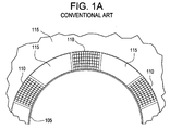
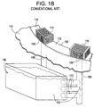
- FIGs 1 A and 1 B illustrate a top view and a perspective view, respectively, of a conventional trash rack arrangement in a BWR.
- the trash racks 110 may be operatively attached to a shield wall 105 and a drywell floor 115 in a position surrounding DCVs 160.
- the trash racks 110 at the drywell inlets 130 may act as a filter for blocking debris from entering the DCVs 160, which lead to a suppression pool 140 through a plurality of horizontal vents 170.
- the suppression pool 140 may include a given amount of water 150.
- the water 150 may flow out of the DCVs 160 through the horizontal vents 170 and into the suppression pool 140, eventually rising to a given level.
- the trash racks 110 function as a deterrent to debris clogging the drywell inlets 130.
- the limited surface area of conventional trash racks may lead to a reduced fluid (i.e., a steam or a liquid) flow through the DCVs 160 when the trash racks 110 become clogged with debris.
- An exemplary embodiment of the present invention is a trash rack for blocking debris from entering a suppression pool of a nuclear reactor, including a cage operatively attached to a shield wall of the nuclear reactor, the cage embodied by a metal grid structure with gaps for permitting passage of debris at a given size, wherein the cage extends continuously around a periphery of the shield wall of the nuclear reactor.
- Another exemplary embodiment of the present invention is a trash rack for blocking debris from entering a suppression pool of a nuclear reactor, including a cage which is attached to a shield wall of the reactor so as to extend continuously around a periphery of the shield wall without interruption.
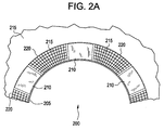
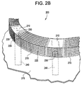
- the trash rack arrangement 200 may include a continuous cage 220 attached to the shield wall 205 and the drywell floor 215.
- the trash rack arrangement 200 may further include solid plates 210, the solid plates 210 being arranged in a position above the DCVs 240 in place of or mounted on the continuous cage 220.
- the solid plates 210 may serve as a protective device from debris impacting the trash track arrangement 200 at high velocities.
- An exemplary solid plate may be composed of a metal.
- the continuous cage 220 may allow fluid flow through the trash rack arrangement 200.
- debris impacts and clogs at least some of the gaps of the continuous cage 220, there may exist additional surface area on the continuous cage 220 at which to allow fluid flow (steam or liquid) through the remaining unclogged gaps.
- debris may include insulation from a broken pipe, for example.
- the debris could be composed of other materials as well.
- a pipe rupture in the BWR may cause debris to travel at substantially high velocities and impact with the trash rack arrangement 200.
- the solid plates 210 may be formed with a given structural integrity so to withstand impact with high-velocity debris without a possibility of rupture. Since the trash rack arrangement 200 is configured to protect the fluid flow through the drywell inlets 230, placing the solid plates 210 in a position over the drywell inlets 230 in place of the continuous cage may deter a potential rupture of the continuous cage 220 from further impacting the drywell inlets 130 after the rupture. It is understood that the solid plates 210 may be placed in any position mounted on continuous cage 220, or in place of the continuous cage 220, in order to provide additional protection against debris impact, and is not limited to being placed or mounted over the drywell inlets 230.
- Figure 3A is a top view of a trash rack arrangement 300 in accordance with another exemplary embodiment of the present invention.
- Figure 3B is an exploded, perspective view illustrating the orientation of the trash rack arrangement 300 of Figure 3A attached to a shield wall 305 and a drywell floor 315 with DCVs 340.
- the trash rack arrangement 300 may include a continuous cage 320 mounted over a shield wall 305.
- the trash rack arrangement 300 may not include solid plates.
- the continuous cage 320 may be uniform with a grid structure throughout the periphery of the trash rack arrangement 300 around the shield wall 305.
- the grid structure of the continuous cage 320 may include gaps (i.e., spaces through which fluid may flow through the continuous cage 320).
- a designer may select whether to include solid plates in the design of the continuous cage 220/320 based on design criteria. For example, the designer may select additional space on the continuous cage 220/320 for solid plates 210 so as to block debris of any size from entering the DCVs 240/340. In another example, if debris with the high expected impact momentum are not expected, the designer may select to limit space on the continuous cage 220/320 for the solid plates 210 in order to maximize the number of useable gaps.
- the continuous cage 220/230 may include a metal grid (i.e., a cage) with gaps.
- the metal grid may include any metal with characteristics suitable for operation in conventional BWRs.
- the cage 220/320 may be formed so that the gaps have a size of 6" x 6", thereby blocking debris in a collision orientation (i.e., a cross-sectional area at a point of impact with the continuous cage 220/320) greater than 6" x 6".
- the continuous cage 220/320 may be formed to a height of about 1.3 meters. In this example, the height may refer to a distance between the ceiling of the continuous cage 220/320 and the drywell floor 215/315.
- the continuous cage 220/320 may also have a width of about 1.0 meters. In this example, the width may refer to a distance between the vertical face of the continuous cage 220/320 and the shield wall 205/305.
- the metal grid may be comprised of round bars having a diameter of less than or equal to 3/8".
- the round bars may be comprised of steel.
Landscapes
- Physics & Mathematics (AREA)
- Engineering & Computer Science (AREA)
- Plasma & Fusion (AREA)
- General Engineering & Computer Science (AREA)
- High Energy & Nuclear Physics (AREA)
- Structure Of Emergency Protection For Nuclear Reactors (AREA)
- Processing Of Solid Wastes (AREA)
Abstract
Description
- The present invention relates generally to a trash rack arrangement, and more particularly to a trash rack arrangement including a continuous cage.
- A boiling water reactor (BWR) is a reactor in which water, used as both coolant and moderator, is allowed to boil in the reactor vessel. The BWR may include a plurality of drywell inlets (i.e., vents). The drywell inlets lead to a suppression pool. The BWR may include a plurality of drywell connecting vents (DCVs). The DCVs may connect the suppression pool to the drywell inlets, which in turn lead to other elements of the BWR, for example the reactor core. The reactor vessel is contained inside the drywell. The DCVs connect the drywell space to the suppression pool. In the event of a rupture or leak of the reactor vessel boundary, the escaping fluid would be contained in the drywell and flow through the DCVs to the suppression pool, where it is cooled and retained. Thus, the high energy-high volume steam may be reduced to a much smaller volume of water at much lower temperatures.
- Figures 1 A and 1 B illustrate a top view and a perspective view, respectively, of a conventional trash rack arrangement in a BWR. Referring to Figures 1A and 1 B, the
trash racks 110 may be operatively attached to ashield wall 105 and adrywell floor 115 in aposition surrounding DCVs 160. The trash racks 110 at thedrywell inlets 130 may act as a filter for blocking debris from entering theDCVs 160, which lead to asuppression pool 140 through a plurality ofhorizontal vents 170. Thesuppression pool 140 may include a given amount ofwater 150. Thewater 150 may flow out of theDCVs 160 through thehorizontal vents 170 and into thesuppression pool 140, eventually rising to a given level. - The trash racks 110 function as a deterrent to debris clogging the
drywell inlets 130. However, the limited surface area of conventional trash racks may lead to a reduced fluid (i.e., a steam or a liquid) flow through theDCVs 160 when thetrash racks 110 become clogged with debris. - An exemplary embodiment of the present invention is a trash rack for blocking debris from entering a suppression pool of a nuclear reactor, including a cage operatively attached to a shield wall of the nuclear reactor, the cage embodied by a metal grid structure with gaps for permitting passage of debris at a given size, wherein the cage extends continuously around a periphery of the shield wall of the nuclear reactor.
- Another exemplary embodiment of the present invention is a trash rack for blocking debris from entering a suppression pool of a nuclear reactor, including a cage which is attached to a shield wall of the reactor so as to extend continuously around a periphery of the shield wall without interruption.
- The exemplary embodiments of the present invention will become more fully understood from the detailed description given herein below with reference to the accompanying drawings which are given by way of illustration only, wherein like reference numerals designate corresponding parts in the various drawings, and in which:
- Figure 1A illustrates a top view of a conventional trash rack arrangement in a boiling water reactor (BWR).
- Figure 1B illustrates a perspective view of the conventional trash rack arrangement of Figure 1 A.
- Figure 2A is a top view of a trash rack arrangement in accordance with an exemplary embodiment of the present invention.
- Figure 2B is an exploded, perspective view illustrating the orientation of the trash rack arrangement of Figure 2A attached to a shield wall and a drywell floor with drywell connecting vents (DCVs).
- Figure 3A is a top view of a trash rack arrangement in accordance with another exemplary embodiment of the present invention.
- Figure 3B is an exploded, perspective view illustrating the orientation of the trash rack arrangement of Figure 3A formed on a shield wall with DCVs.
- Figure 2A is a top view of a
trash rack arrangement 200 in accordance with an exemplary embodiment of the present invention. Figure 2B is an exploded, perspective view illustrating the orientation of thetrash rack arrangement 200 of Figure 2A attached to ashield wall 205 and adrywell floor 215 with drywell connecting vents (DCVs) 240. - The
trash rack arrangement 200 may include acontinuous cage 220 attached to theshield wall 205 and thedrywell floor 215. Thetrash rack arrangement 200 may further includesolid plates 210, thesolid plates 210 being arranged in a position above theDCVs 240 in place of or mounted on thecontinuous cage 220. Thesolid plates 210 may serve as a protective device from debris impacting thetrash track arrangement 200 at high velocities. An exemplary solid plate may be composed of a metal. - In an exemplary embodiment of the present invention, the
continuous cage 220 may allow fluid flow through thetrash rack arrangement 200. Thus, as debris impacts and clogs at least some of the gaps of thecontinuous cage 220, there may exist additional surface area on thecontinuous cage 220 at which to allow fluid flow (steam or liquid) through the remaining unclogged gaps. Such debris may include insulation from a broken pipe, for example. However, the debris could be composed of other materials as well. - In another exemplary embodiment of the present invention, for example in a Lungmen design, a pipe rupture in the BWR may cause debris to travel at substantially high velocities and impact with the
trash rack arrangement 200. Thesolid plates 210 may be formed with a given structural integrity so to withstand impact with high-velocity debris without a possibility of rupture. Since thetrash rack arrangement 200 is configured to protect the fluid flow through thedrywell inlets 230, placing thesolid plates 210 in a position over thedrywell inlets 230 in place of the continuous cage may deter a potential rupture of thecontinuous cage 220 from further impacting thedrywell inlets 130 after the rupture. It is understood that thesolid plates 210 may be placed in any position mounted oncontinuous cage 220, or in place of thecontinuous cage 220, in order to provide additional protection against debris impact, and is not limited to being placed or mounted over thedrywell inlets 230. - Figure 3A is a top view of a
trash rack arrangement 300 in accordance with another exemplary embodiment of the present invention. Figure 3B is an exploded, perspective view illustrating the orientation of thetrash rack arrangement 300 of Figure 3A attached to ashield wall 305 and adrywell floor 315 withDCVs 340. - The
trash rack arrangement 300 may include acontinuous cage 320 mounted over ashield wall 305. Referring to Figures 3A and 3B, in contrast to the embodiment as illustrated in Figures 2A and 2B, thetrash rack arrangement 300 may not include solid plates. Instead, thecontinuous cage 320 may be uniform with a grid structure throughout the periphery of thetrash rack arrangement 300 around theshield wall 305. Referring to Figures 2A and 2B, the grid structure of thecontinuous cage 320 may include gaps (i.e., spaces through which fluid may flow through the continuous cage 320). By having acontinuous cage 320 without solid plates, there may be more gaps in thecontinuous cage 320. In other words, more debris may clog the gaps of thetrash rack arrangement 300 before there may be a fluid flow reduction. - In another exemplary embodiment of the present invention, a designer may select whether to include solid plates in the design of the
continuous cage 220/320 based on design criteria. For example, the designer may select additional space on thecontinuous cage 220/320 forsolid plates 210 so as to block debris of any size from entering theDCVs 240/340. In another example, if debris with the high expected impact momentum are not expected, the designer may select to limit space on thecontinuous cage 220/320 for thesolid plates 210 in order to maximize the number of useable gaps. - In another exemplary embodiment of the present invention, the
continuous cage 220/230 may include a metal grid (i.e., a cage) with gaps. The metal grid may include any metal with characteristics suitable for operation in conventional BWRs. - In an example, the
cage 220/320 may be formed so that the gaps have a size of 6" x 6", thereby blocking debris in a collision orientation (i.e., a cross-sectional area at a point of impact with thecontinuous cage 220/320) greater than 6" x 6". Thecontinuous cage 220/320 may be formed to a height of about 1.3 meters. In this example, the height may refer to a distance between the ceiling of thecontinuous cage 220/320 and thedrywell floor 215/315. Thecontinuous cage 220/320 may also have a width of about 1.0 meters. In this example, the width may refer to a distance between the vertical face of thecontinuous cage 220/320 and theshield wall 205/305. - In another exemplary embodiment of the present invention, the metal grid may be comprised of round bars having a diameter of less than or equal to 3/8". In a further example of this embodiment, the round bars may be comprised of steel.
- The exemplary embodiments of the present invention being thus described, it will be obvious that the same may be varied in many ways. For example, above-described dimensions for the cage are given as examples only. It is understood that different cage dimensions may be used. Further, specific materials given above for various items (i.e., the metal grid,
solid plates 210, etc....) included in thetrash rack arrangement 200/300 are given as exemplary examples only. It is understood that any material suitable for the environment of a BWR and having the general characteristics of the above-described specific examples may be used in the design of thetrash rack arrangement 200/300.
Claims (10)
- A trash rack arrangement (200, 300) for blocking debris from entering a suppression pool (140) of a nuclear reactor, comprising:a cage (220, 320) operatively attached to a shield wall (205, 305) of the nuclear reactor, the cage embodied by a metal grid structure with gaps for permitting passage of debris at a given size, wherein the cage extends continuously around a periphery of the shield wall of the nuclear reactor.
- The trash rack arrangement of claim 1, wherein the metal grid of comprised of round bars.
- The trash rack arrangement of claim 2, wherein the round bars are comprised of steel.
- The trash rack arrangement of claim 1, wherein the cage further includes at least one solid plate (210) in place of a portion of the metal grid, in a position aligned with a drywell connecting vent on the shield wall of the nuclear reactor.
- The trash rack arrangement of claim 1, wherein the cage further includes at least one solid plate (210) mounted on a portion of the metal grid, in a position aligned with a drywell connecting vent on the shield wall of the nuclear reactor.
- The trash rack arrangement of claim 4 or 5, wherein the at least one solid plate is comprised of metal.
- A trash rack arrangement (200, 300) for blocking debris from entering a suppression pool (140) of a nuclear reactor, comprising:a cage (220, 320) which is attached to a shield wall of the reactor so as to extend continuously around a periphery of the shield wall (205, 305) without interruption.
- The trash rack arrangement of claim 7, wherein the cage includes a metal grid structure configured to block debris up to a given cross-sectional size.
- The trash rack arrangement of claim 7, wherein the cage includes one or more solid plate portions (210) arranged between corresponding grid portions of the cage.
- The trash rack arrangement of claim 9, wherein the at least one solid plate is in a position aligned with a drywell connecting vent on the shield wall of the nuclear reactor.
Applications Claiming Priority (1)
| Application Number | Priority Date | Filing Date | Title |
|---|---|---|---|
| US97500804A | 2004-10-28 | 2004-10-28 |
Publications (2)
| Publication Number | Publication Date |
|---|---|
| EP1653479A1 true EP1653479A1 (en) | 2006-05-03 |
| EP1653479B1 EP1653479B1 (en) | 2013-06-26 |
Family
ID=35788988
Family Applications (1)
| Application Number | Title | Priority Date | Filing Date |
|---|---|---|---|
| EP05256363.2A Expired - Lifetime EP1653479B1 (en) | 2004-10-28 | 2005-10-13 | Trash rack arrangement for drywell connecting vents |
Country Status (3)
| Country | Link |
|---|---|
| EP (1) | EP1653479B1 (en) |
| JP (1) | JP4965845B2 (en) |
| TW (1) | TWI352361B (en) |
Cited By (1)
| Publication number | Priority date | Publication date | Assignee | Title |
|---|---|---|---|---|
| JP2015036687A (en) * | 2013-08-09 | 2015-02-23 | ジーイー−ヒタチ・ニュークリア・エナジー・アメリカズ・エルエルシーGe−Hitachi Nuclear Energy Americas, Llc | System for debris mitigation in nuclear reactor safety system |
Families Citing this family (1)
| Publication number | Priority date | Publication date | Assignee | Title |
|---|---|---|---|---|
| RU2778712C1 (en) * | 2021-12-29 | 2022-08-23 | Акционерное Общество "Атомэнергопроект" | Tank for garbage filtration and collection |
Citations (4)
| Publication number | Priority date | Publication date | Assignee | Title |
|---|---|---|---|---|
| US3992256A (en) * | 1973-10-09 | 1976-11-16 | Commissariat A L'energie Atomique | Core support system for a fast reactor |
| US4243485A (en) * | 1977-03-16 | 1981-01-06 | Societe Franco-Americaine De Constructions Atomiques-Framatome | Recirculating drainage channel for the safety circuits of a nuclear reactor |
| EP0390486A2 (en) * | 1989-03-27 | 1990-10-03 | General Electric Company | Nuclear reactor containment safety cooling system |
| JPH0572372A (en) * | 1991-09-10 | 1993-03-26 | Toshiba Corp | Cooling of core debris of nuclear reactor |
Family Cites Families (2)
| Publication number | Priority date | Publication date | Assignee | Title |
|---|---|---|---|---|
| JPS5721076A (en) * | 1980-07-11 | 1982-02-03 | Matsushita Electric Ind Co Ltd | Sealed lead acid battery |
| US5011652A (en) * | 1986-09-19 | 1991-04-30 | Hitachi, Ltd. | Nuclear power facilities |
-
2005
- 2005-10-13 EP EP05256363.2A patent/EP1653479B1/en not_active Expired - Lifetime
- 2005-10-17 TW TW094136191A patent/TWI352361B/en not_active IP Right Cessation
- 2005-10-25 JP JP2005309252A patent/JP4965845B2/en not_active Expired - Lifetime
Patent Citations (4)
| Publication number | Priority date | Publication date | Assignee | Title |
|---|---|---|---|---|
| US3992256A (en) * | 1973-10-09 | 1976-11-16 | Commissariat A L'energie Atomique | Core support system for a fast reactor |
| US4243485A (en) * | 1977-03-16 | 1981-01-06 | Societe Franco-Americaine De Constructions Atomiques-Framatome | Recirculating drainage channel for the safety circuits of a nuclear reactor |
| EP0390486A2 (en) * | 1989-03-27 | 1990-10-03 | General Electric Company | Nuclear reactor containment safety cooling system |
| JPH0572372A (en) * | 1991-09-10 | 1993-03-26 | Toshiba Corp | Cooling of core debris of nuclear reactor |
Non-Patent Citations (1)
| Title |
|---|
| PATENT ABSTRACTS OF JAPAN vol. 017, no. 399 (P - 1579) 26 July 1993 (1993-07-26) * |
Cited By (2)
| Publication number | Priority date | Publication date | Assignee | Title |
|---|---|---|---|---|
| JP2015036687A (en) * | 2013-08-09 | 2015-02-23 | ジーイー−ヒタチ・ニュークリア・エナジー・アメリカズ・エルエルシーGe−Hitachi Nuclear Energy Americas, Llc | System for debris mitigation in nuclear reactor safety system |
| US9715947B2 (en) | 2013-08-09 | 2017-07-25 | Ge-Hitachi Nuclear Energy Americas Llc | Systems for debris mitigation in nuclear reactor safety systems |
Also Published As
| Publication number | Publication date |
|---|---|
| EP1653479B1 (en) | 2013-06-26 |
| TWI352361B (en) | 2011-11-11 |
| JP4965845B2 (en) | 2012-07-04 |
| TW200625343A (en) | 2006-07-16 |
| JP2006126193A (en) | 2006-05-18 |
Similar Documents
| Publication | Publication Date | Title |
|---|---|---|
| US10290379B2 (en) | Passive containment cooling and filtered venting system, and nuclear power plant | |
| US11521759B2 (en) | Melt confinement device | |
| US5867548A (en) | Device and method for collecting and cooling reactor-meltdown products | |
| US7211190B2 (en) | Strainer wall for the screening off of a suction space | |
| EP2581913A1 (en) | Core catcher having an integrated cooling path | |
| US5219517A (en) | Fuel assembly for a boiling water nuclear reactor | |
| CA3203312A1 (en) | Natural circulation heat removal system for a nuclear reactor with pile structure | |
| EP0432738B1 (en) | Fuel assembly for a boiling water nuclear reactor | |
| JPH10319166A (en) | Water reactor containing core recovery device operating in accidental meltdown | |
| JP3854291B2 (en) | Inhalation area screening protective screen | |
| US20060219645A1 (en) | Self-cleaning strainer | |
| EP1653479B1 (en) | Trash rack arrangement for drywell connecting vents | |
| EP1647995A1 (en) | Floor tile debris interceptor and transition plenum in a nuclear power plant | |
| IE46666B1 (en) | A recirculating drainage channel for collecting fluid for recirculation | |
| JP2006113066A5 (en) | ||
| US5192494A (en) | Arrangement for protecting reactor containment integrity | |
| CN108028083A (en) | IRWST nuclear reactor including filtration in water storage tanks | |
| RU2795981C1 (en) | Nuclear reactor core | |
| JPS61271499A (en) | Water control device | |
| Walker et al. | Overview of Site Specific Blockage Solutions at US PWRs | |
| KR820000834B1 (en) | Recirculating drainage channel for teh safety ciruits of a nuclear reactor | |
| Azarian et al. | GAREC analyses in Support of In-Vessel Retention Concept | |
| JP2009121925A (en) | Sloshing overflow control device and fuel storage pool using the same | |
| JPH1082882A (en) | Reactor containment vessel and cooling method thereof | |
| Singh | ON THE ESSENTIAL CHARACTERISTICS OF UNDERGROUND STORAGE OF SPENT NUCLEAR FUEL IN THE HI-STORM 100 SYSTEM |
Legal Events
| Date | Code | Title | Description |
|---|---|---|---|
| PUAI | Public reference made under article 153(3) epc to a published international application that has entered the european phase |
Free format text: ORIGINAL CODE: 0009012 |
|
| AK | Designated contracting states |
Kind code of ref document: A1 Designated state(s): AT BE BG CH CY CZ DE DK EE ES FI FR GB GR HU IE IS IT LI LT LU LV MC NL PL PT RO SE SI SK TR |
|
| AX | Request for extension of the european patent |
Extension state: AL BA HR MK YU |
|
| 17P | Request for examination filed |
Effective date: 20061103 |
|
| 17Q | First examination report despatched |
Effective date: 20061207 |
|
| AKX | Designation fees paid |
Designated state(s): DE FI SE |
|
| GRAP | Despatch of communication of intention to grant a patent |
Free format text: ORIGINAL CODE: EPIDOSNIGR1 |
|
| GRAS | Grant fee paid |
Free format text: ORIGINAL CODE: EPIDOSNIGR3 |
|
| GRAA | (expected) grant |
Free format text: ORIGINAL CODE: 0009210 |
|
| AK | Designated contracting states |
Kind code of ref document: B1 Designated state(s): DE FI SE |
|
| REG | Reference to a national code |
Ref country code: DE Ref legal event code: R096 Ref document number: 602005040132 Country of ref document: DE Effective date: 20130822 |
|
| REG | Reference to a national code |
Ref country code: SE Ref legal event code: TRGR |
|
| PLBE | No opposition filed within time limit |
Free format text: ORIGINAL CODE: 0009261 |
|
| STAA | Information on the status of an ep patent application or granted ep patent |
Free format text: STATUS: NO OPPOSITION FILED WITHIN TIME LIMIT |
|
| 26N | No opposition filed |
Effective date: 20140327 |
|
| REG | Reference to a national code |
Ref country code: DE Ref legal event code: R097 Ref document number: 602005040132 Country of ref document: DE Effective date: 20140327 |
|
| REG | Reference to a national code |
Ref country code: FI Ref legal event code: PCE Owner name: GE HITACHI NUCLEAR ENERGY AMERICAS LLC |
|
| REG | Reference to a national code |
Ref country code: DE Ref legal event code: R081 Ref document number: 602005040132 Country of ref document: DE Owner name: GE-HITACHI NUCLEAR ENERGY AMERICAS LLC, WILMIN, US Free format text: FORMER OWNER: GENERAL ELECTRIC CO., SCHENECTADY, N.Y., US |
|
| PGFP | Annual fee paid to national office [announced via postgrant information from national office to epo] |
Ref country code: FI Payment date: 20240919 Year of fee payment: 20 |
|
| PGFP | Annual fee paid to national office [announced via postgrant information from national office to epo] |
Ref country code: SE Payment date: 20240919 Year of fee payment: 20 |
|
| PGFP | Annual fee paid to national office [announced via postgrant information from national office to epo] |
Ref country code: DE Payment date: 20240919 Year of fee payment: 20 |
|
| REG | Reference to a national code |
Ref country code: DE Ref legal event code: R071 Ref document number: 602005040132 Country of ref document: DE |
|
| REG | Reference to a national code |
Ref country code: SE Ref legal event code: EUG |