EP1653328A2 - A device connector module receptacle - Google Patents
A device connector module receptacle Download PDFInfo
- Publication number
- EP1653328A2 EP1653328A2 EP05256369A EP05256369A EP1653328A2 EP 1653328 A2 EP1653328 A2 EP 1653328A2 EP 05256369 A EP05256369 A EP 05256369A EP 05256369 A EP05256369 A EP 05256369A EP 1653328 A2 EP1653328 A2 EP 1653328A2
- Authority
- EP
- European Patent Office
- Prior art keywords
- connector module
- device connector
- receptacle
- module receptacle
- computer system
- Prior art date
- Legal status (The legal status is an assumption and is not a legal conclusion. Google has not performed a legal analysis and makes no representation as to the accuracy of the status listed.)
- Withdrawn
Links
Images



Classifications
-
- G—PHYSICS
- G06—COMPUTING OR CALCULATING; COUNTING
- G06F—ELECTRIC DIGITAL DATA PROCESSING
- G06F1/00—Details not covered by groups G06F3/00 - G06F13/00 and G06F21/00
- G06F1/16—Constructional details or arrangements
- G06F1/18—Packaging or power distribution
- G06F1/181—Enclosures
-
- G—PHYSICS
- G06—COMPUTING OR CALCULATING; COUNTING
- G06F—ELECTRIC DIGITAL DATA PROCESSING
- G06F1/00—Details not covered by groups G06F3/00 - G06F13/00 and G06F21/00
- G06F1/16—Constructional details or arrangements
- G06F1/18—Packaging or power distribution
- G06F1/183—Internal mounting support structures, e.g. for supporting printed circuit boards
-
- H—ELECTRICITY
- H01—ELECTRIC ELEMENTS
- H01R—ELECTRICALLY-CONDUCTIVE CONNECTIONS; STRUCTURAL ASSOCIATIONS OF A PLURALITY OF MUTUALLY-INSULATED ELECTRICAL CONNECTING ELEMENTS; COUPLING DEVICES; CURRENT COLLECTORS
- H01R13/00—Details of coupling devices of the kinds covered by groups H01R12/70 or H01R24/00 - H01R33/00
- H01R13/46—Bases; Cases
- H01R13/514—Bases; Cases composed as a modular blocks or assembly, i.e. composed of co-operating parts provided with contact members or holding contact members between them
Definitions
- Embodiments of the present invention relate to the field of electronic device connectors. Specifically, embodiments of the present invention relate to a device connector module receptacle.
- a computer system typically includes a number of device connectors in a single Integrated cluster.
- the Integrated cluster may be accessible through an opening in the front bezel of the housing of the computer system.
- the integrated cluster is designed and manufactured to include the particular combination of device connectors for use in conjunction with a particular computer system design.
- the design and manufacturing of the integrated cluster requires the computer system designer to determine which types of device connectors to include.
- a low-end computer system may include an integrated cluster having a small number of device connectors, such as a single Universal Serial Bus (USB) connector and a single audio output
- a high-end computer system may include an integrated cluster having a large number of device connectors, such as multiple USB connectors, multiple IEEE1394 connectors, and various audio and video connectors.
- USB Universal Serial Bus
- Each different integrated cluster of device connectors must be individually designed and manufactured according to the specifications of the different computer systems.
- each different design of integrated cluster is associated with a particular product (e.g., type of computer system), and can only be used with that product.
- the design and manufacturing time required for each integrated cluster increases the time-to-market for the associated product. In this age of fast computer innovations, this added time to market may have an adverse effect on the marketability and realized profit of a product.
- each integrated cluster is product specific, the designers and manufacturers must be very conscientious when ordering and/or producing an integrated cluster for a particular product. For example, if too many integrated clusters are produced, the overall profit generated by the associated product may be reduced, because there will be extra integrated clusters that are not used. Alternatively, if too few Integrated clusters are produced, and an additional number must be reordered for a particular product, various manufacturing costs will be reapplied to the order, also reducing the overall profit of the product. Due to the low profit margins on computer systems, the added cost that may be incurred due to the over-production or under-production of a particular Integrated cluster may be a great factor in decreasing the profit generated by a computer system.
- the device connector module receptacle includes a plurality of slots for receiving a plurality of device connector modules.
- a device connector module includes a device connection mechanism including a first port for coupling to an external device and a second port for coupling to a computer system.
- a device connector module also includes a housing encasing the device connection mechanism such that the first port and the second port are accessible and wherein the housing is for coupling the device connector module to the device connector module receptacle.
- the device connector module receptacle is configured for coupling to a chassis of the computer system.
- Figure 1A is a front perspective diagram of a device connector module 100, in accordance with an embodiment of the present invention.
- Figure 1 B is a cut-away side view of device connector module 100, In accordance with an embodiment of the present invention.
- Device connector module 100 includes a device connection mechanism 110 and a housing 120 for encasing device connection mechanism 110.
- Device connection mechanism 110 is operable to provide a connection for coupling an external device to a computer system.
- Device connection mechanism 110 includes a first port 112 for coupling to the external device and a second port (see second port 114 of Figure 1B) for coupling to the computer system.
- second port is coupled to the computer system over a data cable 116 that terminates in connector 118, wherein connector 118 is operable to be electrically coupled to the computer system.
- Housing 120 encases device connection mechanism 110 such that first port 112 and second port 114 are accessible. In other words, first port 112 and second port 114 are available for receiving connectors of the external device and computer system, respectively. Housing 120 is also configured for coupling device connector module 100 to a device connector module receptacle (e.g., device connector module receptacle 300 of Figures 3A and 3B). In one embodiment, housing 120 is comprised of a plastic material.
- housing 120 includes at least one keying tab 130 for fixedly coupling device connector module 100 to the device connector module receptacle. Keying tabs 130 are snapped into a keying tab aperture of the device connector module receptacle. Housing 120 is operable to be decoupled from the device connector module receptacle by releasing the keying tabs 130. In one embodiment, where housing 120 is comprised of plastic, keying tabs 130 are engaged and released by applying force to keying tabs 130.
- keying tabs 130 are configured such that housing 120 is coupled to a particular position of the device connector module receptacle. In one embodiment, keying tabs 130 are configured such that housing 120 is coupled at a particular orientation to the device connector module receptacle. For example, housing 120 may be configured such that keying tabs 130 for a particular device connector module 100 are placed at specific distances from each other. Also, keying tabs 130 can be placed at a specific distance from the front surface of device connector module 100 (e.g., the surface at which first port 112 is accessible.
- Device connection mechanism 110 may be any connector for electrically coupling an external device to a computer system. It should be appreciated that device connection mechanism 110 may be, but is not limited to, the following connectors:
- a fiber optic network connector such as an SC connector, an ST connector, or an MTRJ connector.
- device connector module 100 includes more than one device connection mechanism 110.
- device connection mechanisms having related functionality may be Included in the same device connector module 100.
- a device connector module 100 may include more than one of the same device connection mechanisms.
- FIG. 2 illustrates front views of different configurations of a device connector module, in accordance with embodiments of the present invention.
- Device connector module 200 includes two USB connectors.
- Device connector module 220 includes one 6-pin IEEE 1394 connector 230.
- Device connector module 240 includes three RCA connectors 250a, 250b and 250c.
- RCA connectors 250a and 250b are audio connectors (e.g., a left-side RCA connector and a right-side RCA connector) and RCA connector 250c is a video connector.
- Device connector module 260 includes an RCA connector 270a and an S-Video connector 270b.
- RCA connector 270a may be either an audio connector or a video connector. It should be appreciated that the configurations of device connector modules 200, 220, 240 and 260 are exemplary, and that any combination of device connection mechanisms may be implemented in the present invention.
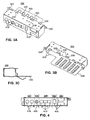
- Figure 3A is a front perspective diagram of a device connector module receptacle 300, in accordance with an embodiment of the present invention.
- Figure 38 is a back perspective diagram of device connector module receptacle 300
- Figure 3C is a side view of device connector module receptacle 300.
- Device connector module receptacle 300 includes a plurality of slots 310 for receiving a plurality of device connector modules (e.g., device connector module 100 of Figures 1A and 1B).
- a slot 310 is configured to provide access to the device connection mechanism of the device connector module associated with the particular slot 310.
- Device connector module receptacle 300 is configured for coupling to a chassis of a computer system. Hooks 322 of device connector module receptacle 300 are configured for engaging device connector module receptacle 300 with the chassis. Aperture 320 is configured to receive a screw for fastening device connector module receptacle 300 to the chassis.
- device connector module receptacle 300 includes an extension 340 that is placed into a drive bay of the chassis. Extension 340 may be fastened to the chassis. It should be appreciated that device connector module receptacle 300 may Include any or all of hooks 322, aperture 320 or extension 340. It should also be appreciated that device connector module receptacle 300 may be connected to a chassis using other well-known techniques that are known by those skilled in the art, and is not limited to the embodiments described herein.
- device connector module receptacle 300 also includes at least one keying tab aperture 330 for receiving a keying tab of the housing of a device connector module.
- the keying tab is engaged with the keying tab aperture for fixedly coupling the device connector module into a slot 310 of device connector module receptacle 300.
- the keying tab aperture is configured such that the device connector module is coupled to a particular slot of device connector module receptacle 300.
- the keying tab aperture is configured such that the device connector module is coupled at a particular orientation to device connector module receptacle 300.
- device connector module receptacle 300 includes a label 350 associated with a slot 310 or group of slots 310. Label 350 provides a user with a visual Indicator as to which type of device connector module is to be placed in a particular location (e.g., slot 310) of device connector module receptacle 300.
- Figure 4 is a front view of an exemplary device connector module receptacle 400, in accordance with an embodiment of the present invention.
- Device connector module receptacle 400 indudes a plurality of slots 410 for receiving device connector modules (e.g., device connector module 100 of Figures 1A and 1B).
- Figure 4 illustrates an example of the placement of particular device connector modules into a particular position of device connector module receptacle 400, as indicated by the dotted lines.
- Position 420 is configured to receive a device connector module having two device connection mechanisms, such as device connector module 260 of Figure 2.
- Position 430 is unused, and is not configured to receive any device connector module. It should be appreciated that knockout 435 may be removed, providing access to position 430 for a device connector module.
- Position 440 is configured to receive a device connector module having three device connection mechanisms, such as device connector module 240 of Figure 2.
- Position 450 is configured to receive a device connector module having one device connection mechanism, such as device connector module 220 of Figure 2.
- Position 460 is configured to receive a device connector module having two device connection mechanisms, where one device connection mechanism is atop the other, such as device connector module 200 of Figure 2. It should be appreciated that the configuration of slots 410 of device connector module receptacle 400 is exemplary, and that device connector module receptacle 400 may include any configuration of slots for placement of any combination of device connector modules.
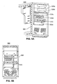
- FIG 5A is a front perspective diagram of a chassis 505 of a computer system 500, in accordance with an embodiment of the present invention.
- Figure 5B is a front view of chassis 505 of computer system 500.
- Computer system 500 includes a plurality of computing components 520a-e that are physically coupled to chassis 505. It should be appreciated that computing components 520a-e may include, but are not limited to CD-ROM drives, floppy disk drives, USB drives, and other removable media drives.
- Device module connector receptacle 510 is also physically coupled to chassis 505. in one embodiment, device module connector receptacle 510 is located in a drive bay of chassis 505.
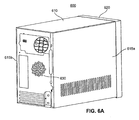
- FIG. 6A is a perspective diagram of the exterior an exemplary computer system housing 600, in accordance with an embodiment of the present invention.
- computer system housing 600 includes top panel 610, side panels 615a and 615b, and front panel (e.g., bezel) 620 secured to chassis 630.
- side panel 615a and front panel 620 are removably attached to chassis 630 for allowing access to the interior of computer system housing 600.
- chassis 630 is metal and top panel 610 and side panels 615a and 615b include a metal layer for encasing the interior of computer system housing 600 in metal.
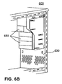
- Figure 6B is a perspective diagram of a portion of the interior of an exemplary computer system housing 600, in accordance with an embodiment of the present invention.
- the front panel of chassis 630 is connected to a number of drive bays 640.
- Drive bays 640 are for holding various drives, including by not limited to CD-ROM drives, floppy disk drives, USB drives, and other removable media drives. It should be appreciated that drive bays 640 may be configured to hold any type or size of drive (e.g., any 5.25 inch drive or 3.5 inch drive).
- Computer system housing 600 of Figures 6A and 6B is also configured to hold the electronic components of a computer system.
- Figure 7 is a block diagram of electronic components of an exemplary computer system 700, in accordance with an embodiment of the present invention.
- computer system 700 includes bus 710 for communicating information, processor 701 coupled with bus 710 for processing information and instructions, random access (volatile) memory (RAM) 702 coupled with bus 710 for storing information and instructions for processor 701, read-only (non-volatile) memory (ROM) 703 coupled with bus 710 for storing static information and instructions for processor 701, data storage device 704 such as a magnetic or optical disk and disk drive coupled with bus 710 for storing information and instructions.
- data storage device 704 is configured to be held In a drive bay 640 of Figure 6B.
- computer system 700 comprises an optional user output device such as display device 705 coupled to bus 710 for displaying information to the computer user, an optional user input device such as alphanumeric input device 707 including alphanumeric and function keys coupled to bus 710 for communicating information and command selections to processor 701, and an optional user input device such as cursor control device 707 coupled to bus 710 for communicating user input information and command selections to processor 701.
- an optional input/output (I/O) device 708 is used to couple computer system 700 onto, for example, a network.
- Display device 705 utilized with computer system 700 may be a liquid crystal device, cathode ray tube, or other display device suitable for creating graphic images and alphanumeric characters recognizable to the user.
- Cursor control device 707 allows the computer user to dynamically signal the two-dimensional movement of a visible symbol (pointer) on a display screen of display device 705.
- cursor control device Many implementations of the cursor control device are known in the art Including a trackball, mouse, joystick or special keys on alphanumeric input device 706 capable of signaling movement of a given direction or manner of displacement.
- the cursor control 707 also may be directed and/or activated via input from the keyboard using special keys and key sequence commands. Alternatively, the cursor may be directed and/or activated via input from a number of specially adapted cursor directing devices.
- FIG 8 is a flow chart diagram of a process 800 for using a device connector module receptacle, in accordance with an embodiment of the present invention. Although specific steps are disclosed in process 800, such steps are exemplary. That is, the embodiments of the present invention are well suited to performing various other steps or variations of the steps recited in Figure 8.
- a device connector module (e.g., device connector module 100 of Figures 1A and 1B) is coupled to a device connector module receptacle (e.g., device connector module receptacle 300 of Figures 3A, 3B and 3C), wherein the device connector module receptacle comprises a plurality of slots for receiving the device connector module.
- step 810 includes steps 820 and 830, as described below.
- the device connector module comprises a keying tab aperture associated with a slot of the plurality of slots. The keying tab aperture is for receiving a keying tab of the device connector module for fixedly coupling said device connector module into at least one slot.
- the keying tab aperture is configured such that the device connector module is coupled to a particular slot of the device connector module receptacle. In one embodiment, the keying tab aperture is configured such that the device connector module is coupled at a particular orientation to the device connector module receptacle.
- the device connector module is placed into a slot of the plurality of slots.
- the device connector module is attached to the device connector module receptacle using the keying tab aperture and the keying tab.
- the device connector module receptacle is coupled to a chassis of a computer system.
- the device connector module receptacle is coupled to a drive bay of the chassis of the computer system.
- the device connector module can include any number or type of device connection mechanisms.
- a computer system designer may select which particular device connector modules to include in a particular computer system. Accordingly, device connector modules may be used across several product lines.
- the computer system designer only needs to design a different device connector module receptacle, improving the time-to-market for the product.
- the profitability of a computer system is not adversely affected by number of device connector modules ordered or manufactured.
- the described embodiments provide improved device connector designs and implementations.
Landscapes
- Engineering & Computer Science (AREA)
- Theoretical Computer Science (AREA)
- Computer Hardware Design (AREA)
- Power Engineering (AREA)
- Human Computer Interaction (AREA)
- Physics & Mathematics (AREA)
- General Engineering & Computer Science (AREA)
- General Physics & Mathematics (AREA)
- Details Of Connecting Devices For Male And Female Coupling (AREA)
- Connector Housings Or Holding Contact Members (AREA)
Abstract
Description
- Embodiments of the present invention relate to the field of electronic device connectors. Specifically, embodiments of the present invention relate to a device connector module receptacle.
- The use of computer systems is virtually ubiquitous in the modern world. Moreover, computer users typically employ a number of external electronic devices, such as digital cameras, digital video cameras, and digital music players (e.g., MP3 players) that provide added user functionality by sharing data with a computer system. To facilitate this data sharing, most recent computer systems provide a number of device connectors for connecting to external devices.
- Typically, a computer system includes a number of device connectors in a single Integrated cluster. The Integrated cluster may be accessible through an opening in the front bezel of the housing of the computer system. The integrated cluster is designed and manufactured to include the particular combination of device connectors for use in conjunction with a particular computer system design. The design and manufacturing of the integrated cluster requires the computer system designer to determine which types of device connectors to include. For example, a low-end computer system may include an integrated cluster having a small number of device connectors, such as a single Universal Serial Bus (USB) connector and a single audio output, while a high-end computer system may include an integrated cluster having a large number of device connectors, such as multiple USB connectors, multiple IEEE1394 connectors, and various audio and video connectors. Each different integrated cluster of device connectors must be individually designed and manufactured according to the specifications of the different computer systems.
- Typically, each different design of integrated cluster is associated with a particular product (e.g., type of computer system), and can only be used with that product. As such, the design and manufacturing time required for each integrated cluster increases the time-to-market for the associated product. In this age of fast computer innovations, this added time to market may have an adverse effect on the marketability and realized profit of a product.
- Moreover, because each integrated cluster is product specific, the designers and manufacturers must be very conscientious when ordering and/or producing an integrated cluster for a particular product. For example, if too many integrated clusters are produced, the overall profit generated by the associated product may be reduced, because there will be extra integrated clusters that are not used. Alternatively, if too few Integrated clusters are produced, and an additional number must be reordered for a particular product, various manufacturing costs will be reapplied to the order, also reducing the overall profit of the product. Due to the low profit margins on computer systems, the added cost that may be incurred due to the over-production or under-production of a particular Integrated cluster may be a great factor in decreasing the profit generated by a computer system.
- Various embodiments of the present invention, a device connector module receptacle, are described herein. The device connector module receptacle includes a plurality of slots for receiving a plurality of device connector modules. A device connector module includes a device connection mechanism including a first port for coupling to an external device and a second port for coupling to a computer system. A device connector module also includes a housing encasing the device connection mechanism such that the first port and the second port are accessible and wherein the housing is for coupling the device connector module to the device connector module receptacle. The device connector module receptacle is configured for coupling to a chassis of the computer system.
- The accompanying drawings, which are incorporated in and form a part of this specification, illustrate embodiments of the invention and, together with the description, serve to explain the principles of the invention:
- FIGURE 1A is a front perspective diagram of a device connector module, in accordance with an embodiment of the present invention.
- FIGURE 1 B is a cut-away side view of a device connector module, in accordance with an embodiment of the present invention.
- FIGURE 2 illustrates front views of different configurations of a device connector module, in accordance with embodiments of the present invention.
- FIGURE 3A Is a front perspective diagram of a device connector module receptacle, in accordance with an embodiment of the present invention.
- FIGURE 3B is a back perspective diagram of a device connector module receptacle, in accordance with an embodiment of the present invention.
- FIGURE 3C is a side view of a device connector module receptacle, in accordance with an embodiment of the present invention.
- FIGURE 4 is a front view of a device connector module receptacle, in accordance with an embodiment of the present invention.
- FIGURE 5A is a front perspective diagram of a chassis of a computer system, in accordance with an embodiment of the present invention.
- FIGURE 5B is a front view of a chassis of a computer system, in accordance with an embodiment of the present invention.
- FIGURE 6A is a perspective diagram of the exterior an exemplary computer system housing, In accordance with an embodiment of the present invention.
- FIGURE 6B is a perspective diagram of a portion of the interior of an exemplary computer system housing, in accordance with an embodiment of the present invention.
- FIGURE 7 is a block diagram of electronic components of an exemplary computer system platform, in accordance with an embodiment of the present invention.
- FIGURE 8 is a flow chart diagram of a process for using a device connector module receptacle, in accordance with an embodiment of the present invention.
- Reference will now be made in detail to various embodiments of the invention, examples of which are illustrated in the accompanying drawings. While the invention will be described in conjunction with these embodiments, it will be understood that they are not intended to limit the invention to these embodiments. On the contrary, the invention is intended to cover alternatives, modifications and equivalents, which may be included within the spirit and scope of the invention as defined by the appended claims. Furthermore, in the following description of the present invention, numerous specific details are set forth in order to provide a thorough understanding of the present invention. In other instances, well-known methods, procedures, components, and circuits have not been described in detail as not to unnecessarily obscure aspects of the present invention.
- Figure 1A is a front perspective diagram of a
device connector module 100, in accordance with an embodiment of the present invention. Figure 1 B is a cut-away side view ofdevice connector module 100, In accordance with an embodiment of the present invention.Device connector module 100 includes adevice connection mechanism 110 and ahousing 120 for encasingdevice connection mechanism 110.Device connection mechanism 110 is operable to provide a connection for coupling an external device to a computer system.Device connection mechanism 110 includes afirst port 112 for coupling to the external device and a second port (seesecond port 114 of Figure 1B) for coupling to the computer system. In one embodiment, second port is coupled to the computer system over adata cable 116 that terminates inconnector 118, whereinconnector 118 is operable to be electrically coupled to the computer system. -
Housing 120 encasesdevice connection mechanism 110 such thatfirst port 112 andsecond port 114 are accessible. In other words,first port 112 andsecond port 114 are available for receiving connectors of the external device and computer system, respectively.Housing 120 is also configured for couplingdevice connector module 100 to a device connector module receptacle (e.g., deviceconnector module receptacle 300 of Figures 3A and 3B). In one embodiment,housing 120 is comprised of a plastic material. - In one embodiment,
housing 120 includes at least onekeying tab 130 for fixedly couplingdevice connector module 100 to the device connector module receptacle.Keying tabs 130 are snapped into a keying tab aperture of the device connector module receptacle.Housing 120 is operable to be decoupled from the device connector module receptacle by releasing thekeying tabs 130. In one embodiment, wherehousing 120 is comprised of plastic, keyingtabs 130 are engaged and released by applying force to keyingtabs 130. - In one embodiment,
keying tabs 130 are configured such thathousing 120 is coupled to a particular position of the device connector module receptacle. In one embodiment,keying tabs 130 are configured such thathousing 120 is coupled at a particular orientation to the device connector module receptacle. For example,housing 120 may be configured such thatkeying tabs 130 for a particulardevice connector module 100 are placed at specific distances from each other. Also,keying tabs 130 can be placed at a specific distance from the front surface of device connector module 100 (e.g., the surface at whichfirst port 112 is accessible. -
Device connection mechanism 110 may be any connector for electrically coupling an external device to a computer system. It should be appreciated thatdevice connection mechanism 110 may be, but is not limited to, the following connectors: - a Universal Serial Bus (USB) connector (Type A or Type B);
- a Mini USB connector (1.0 or 2.0);
- an IEEE 1394 connector (4-pin or 6-pin);
- a video connector, such as an S-Video connector or an RCA connector;
- an audio connector, such as an RCA connector, a 3.5 mm Mini Phone Plug connector, or a Toslink connector for digital audio; and
- • a fiber optic network connector, such as an SC connector, an ST connector, or an MTRJ connector.
- In one embodiment,
device connector module 100 includes more than onedevice connection mechanism 110. For example, device connection mechanisms having related functionality may be Included in the samedevice connector module 100. Also, adevice connector module 100 may include more than one of the same device connection mechanisms. - Figure 2 illustrates front views of different configurations of a device connector module, in accordance with embodiments of the present invention.
Device connector module 200 includes two USB connectors.Device connector module 220 includes one 6-pin IEEE 1394connector 230.Device connector module 240 includes threeRCA connectors RCA connectors RCA connector 250c is a video connector.Device connector module 260 includes anRCA connector 270a and an S-Video connector 270b.RCA connector 270a may be either an audio connector or a video connector. It should be appreciated that the configurations ofdevice connector modules - Figure 3A is a front perspective diagram of a device
connector module receptacle 300, in accordance with an embodiment of the present invention. Similarly, Figure 38 is a back perspective diagram of deviceconnector module receptacle 300 and Figure 3C is a side view of deviceconnector module receptacle 300. Deviceconnector module receptacle 300 includes a plurality ofslots 310 for receiving a plurality of device connector modules (e.g.,device connector module 100 of Figures 1A and 1B). Aslot 310 is configured to provide access to the device connection mechanism of the device connector module associated with theparticular slot 310. - Device
connector module receptacle 300 is configured for coupling to a chassis of a computer system.Hooks 322 of deviceconnector module receptacle 300 are configured for engaging deviceconnector module receptacle 300 with the chassis.Aperture 320 is configured to receive a screw for fastening deviceconnector module receptacle 300 to the chassis. In one embodiment, deviceconnector module receptacle 300 includes anextension 340 that is placed into a drive bay of the chassis.Extension 340 may be fastened to the chassis. It should be appreciated that deviceconnector module receptacle 300 may Include any or all ofhooks 322,aperture 320 orextension 340. It should also be appreciated that deviceconnector module receptacle 300 may be connected to a chassis using other well-known techniques that are known by those skilled in the art, and is not limited to the embodiments described herein. - In one embodiment, device
connector module receptacle 300 also includes at least onekeying tab aperture 330 for receiving a keying tab of the housing of a device connector module. The keying tab is engaged with the keying tab aperture for fixedly coupling the device connector module into aslot 310 of deviceconnector module receptacle 300. In one embodiment, the keying tab aperture is configured such that the device connector module is coupled to a particular slot of deviceconnector module receptacle 300. In one embodiment, the keying tab aperture is configured such that the device connector module is coupled at a particular orientation to deviceconnector module receptacle 300. In one embodiment, deviceconnector module receptacle 300 includes alabel 350 associated with aslot 310 or group ofslots 310.Label 350 provides a user with a visual Indicator as to which type of device connector module is to be placed in a particular location (e.g., slot 310) of deviceconnector module receptacle 300. - Figure 4 is a front view of an exemplary device connector module receptacle 400, in accordance with an embodiment of the present invention. Device connector module receptacle 400 indudes a plurality of
slots 410 for receiving device connector modules (e.g.,device connector module 100 of Figures 1A and 1B). Figure 4 illustrates an example of the placement of particular device connector modules into a particular position of device connector module receptacle 400, as indicated by the dotted lines. -
Position 420 is configured to receive a device connector module having two device connection mechanisms, such asdevice connector module 260 of Figure 2.Position 430 is unused, and is not configured to receive any device connector module. It should be appreciated thatknockout 435 may be removed, providing access toposition 430 for a device connector module.Position 440 is configured to receive a device connector module having three device connection mechanisms, such asdevice connector module 240 of Figure 2.Position 450 is configured to receive a device connector module having one device connection mechanism, such asdevice connector module 220 of Figure 2.Position 460 is configured to receive a device connector module having two device connection mechanisms, where one device connection mechanism is atop the other, such asdevice connector module 200 of Figure 2. It should be appreciated that the configuration ofslots 410 of device connector module receptacle 400 is exemplary, and that device connector module receptacle 400 may include any configuration of slots for placement of any combination of device connector modules. - Figure 5A is a front perspective diagram of a
chassis 505 of acomputer system 500, in accordance with an embodiment of the present invention. Similarly, Figure 5B is a front view ofchassis 505 ofcomputer system 500.Computer system 500 includes a plurality ofcomputing components 520a-e that are physically coupled tochassis 505. It should be appreciated thatcomputing components 520a-e may include, but are not limited to CD-ROM drives, floppy disk drives, USB drives, and other removable media drives. Devicemodule connector receptacle 510 is also physically coupled tochassis 505. in one embodiment, devicemodule connector receptacle 510 is located in a drive bay ofchassis 505. - Figure 6A is a perspective diagram of the exterior an exemplary
computer system housing 600, in accordance with an embodiment of the present invention. As shown,computer system housing 600 includestop panel 610,side panels chassis 630. In one embodiment,side panel 615a andfront panel 620 are removably attached tochassis 630 for allowing access to the interior ofcomputer system housing 600. In one embodiment,chassis 630 is metal andtop panel 610 andside panels computer system housing 600 in metal. - Figure 6B is a perspective diagram of a portion of the interior of an exemplary
computer system housing 600, in accordance with an embodiment of the present invention. As shown, the front panel ofchassis 630 is connected to a number ofdrive bays 640.Drive bays 640 are for holding various drives, including by not limited to CD-ROM drives, floppy disk drives, USB drives, and other removable media drives. It should be appreciated thatdrive bays 640 may be configured to hold any type or size of drive (e.g., any 5.25 inch drive or 3.5 inch drive). -
Computer system housing 600 of Figures 6A and 6B is also configured to hold the electronic components of a computer system. Figure 7 is a block diagram of electronic components of anexemplary computer system 700, in accordance with an embodiment of the present invention. In general,computer system 700 includesbus 710 for communicating information,processor 701 coupled withbus 710 for processing information and instructions, random access (volatile) memory (RAM) 702 coupled withbus 710 for storing information and instructions forprocessor 701, read-only (non-volatile) memory (ROM) 703 coupled withbus 710 for storing static information and instructions forprocessor 701,data storage device 704 such as a magnetic or optical disk and disk drive coupled withbus 710 for storing information and instructions. In one embodiment,data storage device 704 is configured to be held In adrive bay 640 of Figure 6B. - In one embodiment,
computer system 700 comprises an optional user output device such asdisplay device 705 coupled tobus 710 for displaying information to the computer user, an optional user input device such asalphanumeric input device 707 including alphanumeric and function keys coupled tobus 710 for communicating information and command selections toprocessor 701, and an optional user input device such ascursor control device 707 coupled tobus 710 for communicating user input information and command selections toprocessor 701. Furthermore, an optional input/output (I/O)device 708 is used to couplecomputer system 700 onto, for example, a network. -
Display device 705 utilized withcomputer system 700 may be a liquid crystal device, cathode ray tube, or other display device suitable for creating graphic images and alphanumeric characters recognizable to the user.Cursor control device 707 allows the computer user to dynamically signal the two-dimensional movement of a visible symbol (pointer) on a display screen ofdisplay device 705. Many implementations of the cursor control device are known in the art Including a trackball, mouse, joystick or special keys onalphanumeric input device 706 capable of signaling movement of a given direction or manner of displacement. It is to be appreciated that thecursor control 707 also may be directed and/or activated via input from the keyboard using special keys and key sequence commands. Alternatively, the cursor may be directed and/or activated via input from a number of specially adapted cursor directing devices. - Figure 8 is a flow chart diagram of a
process 800 for using a device connector module receptacle, in accordance with an embodiment of the present invention. Although specific steps are disclosed inprocess 800, such steps are exemplary. That is, the embodiments of the present invention are well suited to performing various other steps or variations of the steps recited in Figure 8. - At
step 810 ofprocess 800, a device connector module (e.g.,device connector module 100 of Figures 1A and 1B) is coupled to a device connector module receptacle (e.g., deviceconnector module receptacle 300 of Figures 3A, 3B and 3C), wherein the device connector module receptacle comprises a plurality of slots for receiving the device connector module. In one embodiment,step 810 includessteps 820 and 830, as described below. In one embodiment, the device connector module comprises a keying tab aperture associated with a slot of the plurality of slots. The keying tab aperture is for receiving a keying tab of the device connector module for fixedly coupling said device connector module into at least one slot. In one embodiment, the keying tab aperture is configured such that the device connector module is coupled to a particular slot of the device connector module receptacle. In one embodiment, the keying tab aperture is configured such that the device connector module is coupled at a particular orientation to the device connector module receptacle. - At
step 820, the device connector module is placed into a slot of the plurality of slots. At step 830, the device connector module is attached to the device connector module receptacle using the keying tab aperture and the keying tab. - At
step 840, the device connector module receptacle is coupled to a chassis of a computer system. In one embodiment, the device connector module receptacle is coupled to a drive bay of the chassis of the computer system. - Various embodiments of the present invention provide a device connector module and a device connector module receptacle. The device connector module can include any number or type of device connection mechanisms. By designing and manufacturing a number of different device connector modules, a computer system designer may select which particular device connector modules to include in a particular computer system. Accordingly, device connector modules may be used across several product lines. In order to provide different connectors to different computer systems, the computer system designer only needs to design a different device connector module receptacle, improving the time-to-market for the product. Furthermore, since device connector modules can be used across product lines, the profitability of a computer system is not adversely affected by number of device connector modules ordered or manufactured. Thus, the described embodiments provide improved device connector designs and implementations.
- Embodiments of the present invention, a device connector module receptacle, are thus described. While the present Invention has been described in particular embodiments, it should be appreciated that the present invention should not be construed as limited by such embodiments, but rather construed according to the following claims.
Claims (10)
- A device connector module receptacle 300 comprising:a plurality of slots 310 for receiving a plurality of device connector modules 100, wherein a device connector module 100 of said plurality of device connector modules 100 comprises:a device connection mechanism 110 including a first port 112 for coupling to an external device and a second port 114 for coupling to a computer system 500; anda housing 120 encasing said device connection mechanism 110 such that said first port 112 and said second port 114 are accessible and wherein said housing 120 is for coupling said device connector module 100 to said device connector module receptacle 300;wherein said device connector module receptacle 300 is configured for coupling to a chassis 505 of said computer system 500.
- The device connector module receptacle 300 of Claim 1 further comprising a keying tab aperture 330 at a slot 310 of said plurality of slots 310, said keying tab aperture 330 for receiving a keying tab 130 of said housing 120 for fixedly coupling a device connector module 100 into a slot 310 to said device connector module receptacle 300.
- The device connector module receptacle of 300 Claim 2 wherein said keying tab aperture 330 is configured such that said device connector module 100 is coupled to a particular slot 310 of said device connector module receptacle 300 and at a particular orientation.
- The device connector module receptacle 300 of Claim 1 wherein said device connector module 100 is configured for coupling to a drive bay of said chassis 505.
- The device connector module receptacle 300 of Claim 1 wherein said plurality of device connector modules 100 includes a Universal Serial Bus (USB) connector module.
- The device connector module receptacle 300 of Claim 1 wherein said plurality of device connector modules 100 includes an IEEE 1394 connector module.
- The device connector module receptacle 300 of Claim 1 wherein said plurality of device connector modules 100 includes a video connector module.
- The device connector module receptacle 300 of Claim 1 wherein said plurality of device connector modules 100 includes an audio connector module.
- A method for using a device connector module receptacle 300, said method comprising:coupling a device connector module 100 to said device connector module receptacle 300, said device connector module receptacle 300 comprising a plurality of slots 310 for receiving said device connector module 100; andcoupling said device connector module receptacle 300 to a chassis 505 of a computer system 500.
- The method as recited in Claim 9 wherein said device connector module receptacle 300 comprises a keying tab aperture 330 associated with a slot 310 of said plurality of slots 310, said keying tab aperture 330 for receiving a keying tab 130 of said device connector module 100 for fixedly coupling said device connector module 100 into a slot 310 of said plurality of slots 310.
Applications Claiming Priority (1)
| Application Number | Priority Date | Filing Date | Title |
|---|---|---|---|
| US10/974,314 US20060087806A1 (en) | 2004-10-26 | 2004-10-26 | Device connector module receptacle |
Publications (2)
| Publication Number | Publication Date |
|---|---|
| EP1653328A2 true EP1653328A2 (en) | 2006-05-03 |
| EP1653328A3 EP1653328A3 (en) | 2009-12-16 |
Family
ID=35500623
Family Applications (1)
| Application Number | Title | Priority Date | Filing Date |
|---|---|---|---|
| EP05256369A Withdrawn EP1653328A3 (en) | 2004-10-26 | 2005-10-13 | A device connector module receptacle |
Country Status (3)
| Country | Link |
|---|---|
| US (1) | US20060087806A1 (en) |
| EP (1) | EP1653328A3 (en) |
| CN (1) | CN1767278B (en) |
Families Citing this family (3)
| Publication number | Priority date | Publication date | Assignee | Title |
|---|---|---|---|---|
| US20060089056A1 (en) * | 2004-10-26 | 2006-04-27 | Ng Kai M | Device connector module |
| CN102811579A (en) * | 2011-05-31 | 2012-12-05 | 富泰华工业(深圳)有限公司 | Electronic device and its conductive structure |
| TWI686116B (en) * | 2018-04-30 | 2020-02-21 | 佳必琪國際股份有限公司 | Integration device for integrating function modules |
Family Cites Families (14)
| Publication number | Priority date | Publication date | Assignee | Title |
|---|---|---|---|---|
| US5129842A (en) * | 1991-04-08 | 1992-07-14 | Digital Equipment Corporation | Modular patch panel |
| US5347430A (en) * | 1993-04-06 | 1994-09-13 | Dell Usa, L.P. | Computer chassis construction |
| US5684271A (en) * | 1994-07-14 | 1997-11-04 | Dell Usa, L.P. | Configurationally variable computer chassis/EMI shield apparatus and associated fabrication methods |
| US5666267A (en) * | 1994-12-19 | 1997-09-09 | Intel Corporation | Front panel audio I/O apparatus for personal computer systems |
| DE29822734U1 (en) * | 1997-12-11 | 1999-02-25 | Joh. Vaillant Gmbh U. Co, 42859 Remscheid | Top with insert frame |
| US6064568A (en) * | 1998-01-27 | 2000-05-16 | Dell Usa, L.P. | Computer system with peripheral device carrier |
| CN2383112Y (en) * | 1999-03-11 | 2000-06-14 | 富金精密工业(深圳)有限公司 | Computer configuration structure |
| US6215656B1 (en) * | 1999-06-18 | 2001-04-10 | Dell Usa, L.P. | Method and apparatus for factory or user configurable external connectors |
| DE29918177U1 (en) * | 1999-10-14 | 2000-01-05 | Kan, Chin-Mao, Chung Li | Chassis for wire connection in two levels |
| US6307756B1 (en) * | 2000-06-27 | 2001-10-23 | Hon Hai Precision Ind. Co., Ltd. | Connector holder with conductive shield |
| ES2169705B1 (en) * | 2000-12-28 | 2004-06-01 | Antonio B. Garcia Llorens | FRONT PANEL EXTENSION CONNECTORS FOR PC AND SIMILAR. |
| US6718408B2 (en) * | 2001-01-18 | 2004-04-06 | Hewlett-Packard Development Company, L.P. | Interchangeable and configurable input/output module for a computing deviceco |
| CN2636289Y (en) * | 2003-04-14 | 2004-08-25 | 微星科技股份有限公司 | computer wireless network |
| US7248469B2 (en) * | 2003-09-05 | 2007-07-24 | Finisar Corporation | Plug-in electronic module and method for connecting a plug-in electronic module to a holding structure |
-
2004
- 2004-10-26 US US10/974,314 patent/US20060087806A1/en not_active Abandoned
-
2005
- 2005-10-13 EP EP05256369A patent/EP1653328A3/en not_active Withdrawn
- 2005-10-26 CN CN2005101180464A patent/CN1767278B/en not_active Expired - Fee Related
Also Published As
| Publication number | Publication date |
|---|---|
| CN1767278A (en) | 2006-05-03 |
| US20060087806A1 (en) | 2006-04-27 |
| EP1653328A3 (en) | 2009-12-16 |
| CN1767278B (en) | 2012-05-16 |
Similar Documents
| Publication | Publication Date | Title |
|---|---|---|
| US10362707B2 (en) | Reduced depth data storage assembly and rack server | |
| US8432684B2 (en) | Computer enclosure and data storage device bracket of the computer enclosure | |
| US7099151B2 (en) | Modular computer system and components therefor | |
| JP5468685B2 (en) | Component assembly | |
| US5666557A (en) | Method and apparatus for automatically assigning device identifiers on a parallel data bus | |
| US6724619B2 (en) | Console drive | |
| US7940520B2 (en) | Removable display cover | |
| US7307834B2 (en) | Modular computer system and components therefor | |
| US6654842B1 (en) | Swap bay device supporting both master mode and slave mode and portable computer having the same | |
| US8482925B2 (en) | High-density computer system | |
| US7384276B2 (en) | Electronic device with hot swap capability | |
| GB2319400A (en) | Connector for receiving two computer cards | |
| EP0486146A2 (en) | Personal computer with input/output subsystem | |
| US7190575B1 (en) | Hard disk drive system and keying method | |
| US20120262874A1 (en) | Motherboard and server using the same | |
| EP1653328A2 (en) | A device connector module receptacle | |
| EP1653329A2 (en) | A device connector module | |
| US7465189B2 (en) | Method and apparatus for electrically coupling a component to an information handling system | |
| US20070234379A1 (en) | Method and apparatus for coupling an optical drive to a chassis | |
| US7539008B2 (en) | Closing mechanism | |
| US20060259918A1 (en) | Method and apparatus for mounting a storage device in an information handling system | |
| US20080090611A1 (en) | System and Method for Information Handling System Modular Wireless Integration | |
| US20030172216A1 (en) | Increasing the component capacity of adapters | |
| KR100822888B1 (en) | Car Computer | |
| AU648309B2 (en) | Apparatus and method for assembly of direct access storage device with a personal computer |
Legal Events
| Date | Code | Title | Description |
|---|---|---|---|
| PUAI | Public reference made under article 153(3) epc to a published international application that has entered the european phase |
Free format text: ORIGINAL CODE: 0009012 |
|
| AK | Designated contracting states |
Kind code of ref document: A2 Designated state(s): AT BE BG CH CY CZ DE DK EE ES FI FR GB GR HU IE IS IT LI LT LU LV MC NL PL PT RO SE SI SK TR |
|
| AX | Request for extension of the european patent |
Extension state: AL BA HR MK YU |
|
| PUAL | Search report despatched |
Free format text: ORIGINAL CODE: 0009013 |
|
| AK | Designated contracting states |
Kind code of ref document: A3 Designated state(s): AT BE BG CH CY CZ DE DK EE ES FI FR GB GR HU IE IS IT LI LT LU LV MC NL PL PT RO SE SI SK TR |
|
| AX | Request for extension of the european patent |
Extension state: AL BA HR MK YU |
|
| AKY | No designation fees paid | ||
| STAA | Information on the status of an ep patent application or granted ep patent |
Free format text: STATUS: THE APPLICATION IS DEEMED TO BE WITHDRAWN |
|
| 18D | Application deemed to be withdrawn |
Effective date: 20100617 |
|
| REG | Reference to a national code |
Ref country code: DE Ref legal event code: 8566 |