EP1653133A1 - Valve - Google Patents
Valve Download PDFInfo
- Publication number
- EP1653133A1 EP1653133A1 EP04425810A EP04425810A EP1653133A1 EP 1653133 A1 EP1653133 A1 EP 1653133A1 EP 04425810 A EP04425810 A EP 04425810A EP 04425810 A EP04425810 A EP 04425810A EP 1653133 A1 EP1653133 A1 EP 1653133A1
- Authority
- EP
- European Patent Office
- Prior art keywords
- diaphragm
- shape
- memory
- support
- wire
- Prior art date
- Legal status (The legal status is an assumption and is not a legal conclusion. Google has not performed a legal analysis and makes no representation as to the accuracy of the status listed.)
- Granted
Links
Images


Classifications
-
- F—MECHANICAL ENGINEERING; LIGHTING; HEATING; WEAPONS; BLASTING
- F16—ENGINEERING ELEMENTS AND UNITS; GENERAL MEASURES FOR PRODUCING AND MAINTAINING EFFECTIVE FUNCTIONING OF MACHINES OR INSTALLATIONS; THERMAL INSULATION IN GENERAL
- F16K—VALVES; TAPS; COCKS; ACTUATING-FLOATS; DEVICES FOR VENTING OR AERATING
- F16K31/00—Actuating devices; Operating means; Releasing devices
- F16K31/02—Actuating devices; Operating means; Releasing devices electric; magnetic
- F16K31/025—Actuating devices; Operating means; Releasing devices electric; magnetic actuated by thermo-electric means
Definitions
- the shortening of the wire 13 causes the diametrically opposite areas of the peripheral frame 11, to which it is connected, to tend to line up in the same plane, with the central part of the wire in contact with the central frame 10.
- This brings about an axial displacement of the peripheral frame: 11 up to the opposite position illustrated in Figure 3, said movement being favoured by the diaphragm 9 itself, once the latter has exceeded its dead-centre condition.
- the wire 13 can be deactivated, in so far as the elasticity of the diaphragm 9 itself tends to maintain the peripheral frame 11 in the condition illustrated in Figure 3, set at a distance from the edge of the opening 4 of the casing 2.
- the device according to the invention can also be used for controlling, in a variable way, the cross section of passage of a pipe, for example, for a gas.
- a pipe for example, for a gas.
Landscapes
- Engineering & Computer Science (AREA)
- General Engineering & Computer Science (AREA)
- Mechanical Engineering (AREA)
- Temperature-Responsive Valves (AREA)
- Multiple-Way Valves (AREA)
- Electrically Driven Valve-Operating Means (AREA)
- Magnetically Actuated Valves (AREA)
- Accessories For Mixers (AREA)
Abstract
Description
- The present invention relates to the field of valves for gases, liquids or powdery material.
- The purpose of the invention is to provide a valve of the type specified above, which will have an extremely simple and low-cost structure and which will even so be efficient in its operation.
- In order to achieve said purpose, the subject of the present invention is a valve comprising a diaphragm shutter element having a central part and a peripheral edge, which are mobile axially with respect to one another between a first relative end position and a second relative end position, which correspond, respectively, to the open condition and to the closed condition of the valve, or vice versa, and shape-memory actuator means for controlling the position of said central part and of said peripheral edge with respect to one another.
- In the preferred embodiment, connected to the central part and to the peripheral edge of the diaphragm shutter element are, respectively, a first support and a second support, and said shape-memory means are set between said supports. Once again in the case of the preferred embodiment, the diaphragm shutter element is found in a stable resting configuration in each of the two aforesaid relative end positions of said central part and of said peripheral edge. Preferably, moreover, the shape-memory actuator means comprise first shape-memory actuator means for displacing the diaphragm towards the aforesaid first relative end position and second shape-memory actuator means for displacing the diaphragm towards said second relative end position. In the case of said preferred embodiment, the diaphragm is shaped so as to present a configuration of intermediate dead centre between the two relative end positions of the peripheral edge and of the central part. When the diaphragm is moved away from the configuration corresponding to the first end position, it tends of course to be displaced into the opposite configuration, corresponding to the second relative end position, once it has exceeded the intermediate dead-centre configuration. Consequently, in said preferred embodiment, said first and said second shape-memory actuator means are able to bring about each displacement of the diaphragm from one configuration to the other simply by moving it away from the starting position until it exceeds the intermediate dead-centre configuration.
- A particularly advantageous application of the valve according to the invention is to the control of the passage of air in a position corresponding to an opening for ventilation of the type, for example, used in the cabs of lorries. However, the application of the valve according to the invention is altogether general and extends also to the field of gases, liquids or powdery materials.
- It is also possible to think of a valve built in compliance with the teachings of the present invention, which will have a monostable diaphragm shutter element, instead of a bistable one, as in the case of the preferred embodiment. This means that the diaphragm shutter element is found in a resting condition only in one of the two aforesaid relative end positions of the central part and of the peripheral edge of the diaphragm. The shape-memory actuator means are prearranged for displacing the shutter element into the opposite position, and there may be, for example, provided elastic means tending to recall the diaphragm shutter element into the resting condition when activation of the shape-memory means ceases.
- Once again in the case of the preferred embodiment, the first and second shape-memory means are each constituted by a wire formed by a shape-memory alloy set on a respective face of the diaphragm shutter element, so as to engage two diametrically opposite areas of the peripheral edge thereof, as well as the central part of the diaphragm. The shape-memory wire is activated by causing it to be traversed by electric current. In the activated condition, the shape-memory wire tends to cause the diaphragm to exceed its dead-centre configuration. Advantageously, the wire prearranged on each of the two faces of the diaphragm can be made to turn back in the form of a U, with two parallel branches, so as to present its two opposite ends adjacent to one another, on the same side of the diaphragm, for a more convenient connection with electrical-supply means. Said means are responsible for heating the wire by the Joule effect, which brings about an increase in temperature thereof until the transition temperature is exceeded at which contraction of the wire occurs.
- Of course, the electrical supply of the first and second shape-memory means is advantageously controlled by electronic-control means that activate selectively the first and second shape-memory means following-upon an intervention of the operator on control means that control the valve.
- Also envisaged is the case of a monostable diaphragm shutter element, which is moved away from the resting position by means of a proportional control of the electric current supplied to the shape-memory wire for the purpose of positioning the shutter element in a variable way, with a closed-loop control performed on the basis of a feedback signal constituted, for example, by a signal indicating a parameter, such as the temperature of the wire, the position of the shutter element or of the wire, the electrical resistance of the wire, or the current supplied.
- Further characteristics and advantages of the invention will emerge from the ensuing description, with reference to the annexed drawings, which are provided purely by way of non-limiting example and in which:
- Figure 1 is a partially sectioned perspective view of an opening for the ventilation air in the cab of a lorry, which is provided with a valve according to a preferred embodiment of the invention; and
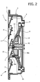
- Figures 2 and 3 are cross-sectional views of the opening of Figure 1 in two different operative conditions.
- With reference to the drawings,
number 1 designates as a whole an opening designed to enable outlet of the ventilation air from the cab of a lorry. Of course, the example given herein has no limiting effect on the applicability of the invention, which is altogether general. The valve according to the invention can in fact be associated to any type of opening or passage for air in any type of device or else can be used as a valve for liquids or for powdery material, in any suitable application. - With reference to the specific example, the
opening 1 comprises a shell orcasing 2 made of plastic material having a box-like conformation, with anend wall 3 having acircular opening 4 and an opposite open side having aperimetral edge 5 in a position corresponding to which there is mounted aframe 6 with a plurality ofparallel fins 7 set at a distance apart from one another, rigidly connected to theframe 6 and defining between them slits 8 for exit of the air coming from the cab of the lorry. Obviously, as has been said, an opening or louver of the type illustrated herein could be used also as ventilation outlet in buildings or premises of any type, such as, for example, greenhouses or industrial sheds. Communication through theopening 4 is controlled by adiaphragm shutter element 9, comprising a membrane made of rubber with a central part fixed to afirst support 10 and a peripheral sealing edge, which is fixed to anannular support 11 and is able to ensure sealing in an area corresponding to the edge of thecircular opening 4. Therubber diaphragm 9 is deformable so as to enable a relative axial displacement of theperipheral support 11 with respect to thecentral part 10, which is connected rigidly, by means of supportingrods 10a, to the structure of theframe 6. Theperipheral support 11 is consequently displaceable axially, with respect to thecasing 2 of the opening, between a first operative position, illustrated in Figure 2, in which the peripheral edge 9a of thediaphragm 9 ensures tightness in an area corresponding to theopening 4, and an opposite position (Figure 3), in which theannular support 11 is set at an axial distance apart from theopening 4 so that the air is free to pass through said opening and to come out through theslits 8. Therubber diaphragm 9 has a dead-centre configuration, so that when it is moved away from one of its two opposite configurations, illustrated in Figures 2 and 3, it is displaced as a result of its own elasticity towards the other configuration, once the dead centre is exceeded. - Movement of the
diaphragm shutter element 9 between the two extreme conditions illustrated in Figures 2 and 3 is controlled by means of a first wire and a second wire, which are made of a shape-memory metal alloy and are designated, respectively, by 12 and 13. Preferably, as illustrated, each of the twowires appendage 11a of the edge of theperipheral frame 11 so as to present the two ends adjacent to one another in electrical connection with twocontacts 14 that are to be connected to electrical-supply means (not illustrated). In the deactivated condition, the shape-memory wire is in a distended condition (like thewire 13 in Figure 2 or thewire 12 in Figure 3). Assuming the condition of Figure 2, electrical supply of thewire 13 causes contraction thereof. Since the wire is secured to theperipheral frame 11 in two diametrically opposite areas thereof, the shortening of thewire 13 causes the diametrically opposite areas of theperipheral frame 11, to which it is connected, to tend to line up in the same plane, with the central part of the wire in contact with thecentral frame 10. This brings about an axial displacement of the peripheral frame: 11 up to the opposite position illustrated in Figure 3, said movement being favoured by thediaphragm 9 itself, once the latter has exceeded its dead-centre condition. Once the condition illustrated in Figure 3 is reached, thewire 13 can be deactivated, in so far as the elasticity of thediaphragm 9 itself tends to maintain theperipheral frame 11 in the condition illustrated in Figure 3, set at a distance from the edge of theopening 4 of thecasing 2. As has already been said, in said condition, a flow of air F coming from the internal environment can enter thecasing 2 and flow out through theslits 8. When it is desired to close the opening again, it is sufficient to activate thewire 12 so as to cause a contraction thereof, which brings about the displacement of theperipheral frame 11 with respect to thecentral part 10 into the relative position illustrated in Figure 2. Also during said passage, the movement is encouraged by the elasticity of thediaphragm 9 itself once it has exceeded its dead-centre configuration. - Of course, as has already been illustrated a number of times, even though the preferred example of embodiment described herein makes use of a bistable diaphragm, it would also be possible to envisage the use of a monostable diaphragm shutter element, in which shape-memory actuator means are used for moving the diaphragm away from its stable condition and elastic means are used for recalling the diaphragm into said configuration after a deactivation of the shape-memory means.
- Also the conformation and arrangemerit of the shape-memory means can be any whatsoever, even though the one illustrated herein presents particular advantages of simplicity and efficiency.
- The device according to the invention can also be used for controlling, in a variable way, the cross section of passage of a pipe, for example, for a gas. In this case it is, for example, possible to provide an annular valve body above one end of the pipe and possibly control the diaphragm shutter element in a proportional way, with a closed-loop control, as already mentioned above.
- Of course, without prejudice to the principle of the invention, the details of construction and the embodiments may vary widely with respect to what is described and illustrated herein purely by of way of example, without thereby departing from the scope of the present invention.
Claims (9)
- A valve for gases, liquids or powdery material, comprising a diaphragm shutter element (9) having a central part and a peripheral edge, which are mobile axially with respect to one another between a first relative end position and a second relative end position, which correspond, respectively, to the open condition and to the closed condition of the valve, or vice versa, and shape-memory actuator means (12, 13) for controlling the position of said central part and said peripheral edge with respect to one another.
- The valve according to Claim 1, characterized in that the central part and the peripheral edge of the diaphragm (9) are connected, respectively, to a first support (10) and a second support (11) and in that said shape-memory means (12, 13) are set operatively between said first and second supports (10, 11).
- The valve according to Claim 1, characterized in that said diaphragm is monostable, i.e., it has a single stable resting configuration, corresponding to one of the aforesaid relative end positions, and in that said shape-memory means tend to move said diaphragm away from the aforesaid stable configuration, and in that elastic means are provided for recalling the diaphragm back into said stable configuration after a deactivation of the shape-memory means.
- The valve according to Claim 1, characterized in that said diaphragm (9) is bistable; i.e., it has a stable resting configuration in each of the two aforesaid relative end positions and has an intermediate dead-centre position so that the diaphragm tends, as a result of its own elasticity, to move towards one of said stable configurations, when it is moved away from the other, until it exceeds the aforesaid dead-centre position.
- The valve according to Claim 4, characterized in that it has first and second shape-memory means (12, 13) for pushing the diaphragm (9) towards said first and towards said second relative end positions, respectively.
- The valve according to Claim 5, characterized in that said first and second shape-memory means comprise a first shape-memory wire (12) and a second shape-memory wire (13), set on the two faces of the aforesaid diaphragm (9) and connected in diametrically opposite areas of said second support (11) so as to tend to modify the position of said first support and said second support with respect to one another when they are activated.
- The valve according to Claim 6, characterized in that it comprises electrical-supply means for supplying said first and second shape-memory wires (12, 13) so as to cause an increase in the temperature thereof as a result of the passage of electric current until the respective transition temperature is exceeded.
- The valve according to Claim 7, characterized in that it comprises a shell or casing (2), with an end wall (3) having an opening (4) controlled by said diaphragm shutter element (9), said casing (2) having an open side, in which there is mounted a frame (6) defining a plurality of slits (8) for exit of air, said first central support of said diaphragm shutter element (9) being connected to said frame, and said second peripheral support (11) being mobile axially with respect to said support between a first position in which it is in contact with the edge of the aforesaid opening (4) so as to seal it and a position axially set at a distance from the first, in which the passage of air through said openings (4) is enabled.
- The valve according to Claim 1, characterized in that there is provided a monostable diaphragm shutter element that is moved away from the resting position by means of a proportional control of the electric current supplied to the shape-memory wire, for the purpose of positioning the shutter element in a variable way, with a closed-loop control performed on the basis of a feedback signal constituted, for example, by a signal indicating a parameter such as the temperature of the wire, the position of the shutter element or of the wire, the electrical resistance of the wire, or the current supplied.
Priority Applications (6)
| Application Number | Priority Date | Filing Date | Title |
|---|---|---|---|
| DE602004009085T DE602004009085T2 (en) | 2004-10-28 | 2004-10-28 | Valve |
| AT04425810T ATE373795T1 (en) | 2004-10-28 | 2004-10-28 | VALVE |
| EP04425810A EP1653133B1 (en) | 2004-10-28 | 2004-10-28 | Valve |
| US11/244,388 US7198248B2 (en) | 2004-10-28 | 2005-10-06 | Valve for fluids, liquids or powder material having a diaphragm shutter controlled by shape memory means |
| JP2005313030A JP2006125635A (en) | 2004-10-28 | 2005-10-27 | Valve for fluid, liquid or powder material having a diaphragm shutter controlled by shape memory means |
| CNA2005101184361A CN1766383A (en) | 2004-10-28 | 2005-10-28 | Valve for fluids, liquids or powder material having a diaphragm shutter controlled by shape memory means |
Applications Claiming Priority (1)
| Application Number | Priority Date | Filing Date | Title |
|---|---|---|---|
| EP04425810A EP1653133B1 (en) | 2004-10-28 | 2004-10-28 | Valve |
Publications (2)
| Publication Number | Publication Date |
|---|---|
| EP1653133A1 true EP1653133A1 (en) | 2006-05-03 |
| EP1653133B1 EP1653133B1 (en) | 2007-09-19 |
Family
ID=34932854
Family Applications (1)
| Application Number | Title | Priority Date | Filing Date |
|---|---|---|---|
| EP04425810A Expired - Lifetime EP1653133B1 (en) | 2004-10-28 | 2004-10-28 | Valve |
Country Status (6)
| Country | Link |
|---|---|
| US (1) | US7198248B2 (en) |
| EP (1) | EP1653133B1 (en) |
| JP (1) | JP2006125635A (en) |
| CN (1) | CN1766383A (en) |
| AT (1) | ATE373795T1 (en) |
| DE (1) | DE602004009085T2 (en) |
Cited By (2)
| Publication number | Priority date | Publication date | Assignee | Title |
|---|---|---|---|---|
| EP1762764A1 (en) | 2005-09-08 | 2007-03-14 | C.R.F. Societa Consortile per Azioni | Diaphragm valve with shape memory actuator |
| GB2469298A (en) * | 2009-04-08 | 2010-10-13 | Kohler Mira Ltd | Valve with shape memory alloy |
Families Citing this family (9)
| Publication number | Priority date | Publication date | Assignee | Title |
|---|---|---|---|---|
| WO2008115264A2 (en) * | 2006-09-11 | 2008-09-25 | California Institute Of Technology | Electrically actuated valves made from shape memory alloy wires embedded in elastomer |
| US8499779B2 (en) | 2008-01-16 | 2013-08-06 | The United States Of America As Represented By The Administrator Of The National Aeronautics Space Administration | Systems, methods and apparatus of a nitinol valve |
| WO2010019626A1 (en) * | 2008-08-14 | 2010-02-18 | Autosplice Inc. | Multi-stable actuation apparatus and methods for making and using the same |
| US8851443B2 (en) * | 2010-12-15 | 2014-10-07 | Autosplice, Inc. | Memory alloy-actuated apparatus and methods for making and using the same |
| US9027903B2 (en) | 2010-12-15 | 2015-05-12 | Autosplice, Inc. | Power-efficient actuator assemblies and methods of manufacture |
| CN104040871B (en) | 2011-10-26 | 2016-11-16 | 奥图斯普公司 | Memory alloy actuating device and method of manufacturing and using the same |
| ITMI20112121A1 (en) * | 2011-11-22 | 2013-05-23 | Getters Spa | SYSTEM FOR THE PRODUCTION OF HOT WATER AND AUTOMATIC DRINK OF DRINKS THAT USES IT |
| US9212754B2 (en) * | 2013-03-12 | 2015-12-15 | A. Raymond Et Cie | Shape memory alloy valve |
| EP4065843B1 (en) * | 2020-03-30 | 2023-01-04 | Saes Getters S.p.A. | Bistable shape memory alloy inertial actuator |
Citations (5)
| Publication number | Priority date | Publication date | Assignee | Title |
|---|---|---|---|---|
| US3974849A (en) * | 1974-09-04 | 1976-08-17 | Dawson Peter L | Diaphragm valves |
| JPS59103088A (en) * | 1982-12-01 | 1984-06-14 | Keiichi Yasukawa | Valve making use of shape memory alloy |
| JPS616470A (en) * | 1984-06-19 | 1986-01-13 | Matsushita Refrig Co | Temperature sensing working valve |
| JPS61236974A (en) * | 1985-04-11 | 1986-10-22 | Matsushita Electric Ind Co Ltd | fluid control valve |
| US20020171055A1 (en) * | 2001-04-10 | 2002-11-21 | Johnson A. David | Miniature latching valve |
Family Cites Families (5)
| Publication number | Priority date | Publication date | Assignee | Title |
|---|---|---|---|---|
| US5058856A (en) * | 1991-05-08 | 1991-10-22 | Hewlett-Packard Company | Thermally-actuated microminiature valve |
| US5345963A (en) * | 1993-03-31 | 1994-09-13 | Honeywell Inc. | Modulating pressure regulator with shape memory alloy actuator |
| US5325880A (en) * | 1993-04-19 | 1994-07-05 | Tini Alloy Company | Shape memory alloy film actuated microvalve |
| US5785295A (en) * | 1996-08-27 | 1998-07-28 | Industrial Technology Research Institute | Thermally buckling control microvalve |
| DE19735156C1 (en) * | 1996-11-25 | 1999-04-29 | Fraunhofer Ges Forschung | Piezo-electrically operated micro valve |
-
2004
- 2004-10-28 AT AT04425810T patent/ATE373795T1/en not_active IP Right Cessation
- 2004-10-28 EP EP04425810A patent/EP1653133B1/en not_active Expired - Lifetime
- 2004-10-28 DE DE602004009085T patent/DE602004009085T2/en not_active Expired - Lifetime
-
2005
- 2005-10-06 US US11/244,388 patent/US7198248B2/en not_active Expired - Fee Related
- 2005-10-27 JP JP2005313030A patent/JP2006125635A/en active Pending
- 2005-10-28 CN CNA2005101184361A patent/CN1766383A/en active Pending
Patent Citations (5)
| Publication number | Priority date | Publication date | Assignee | Title |
|---|---|---|---|---|
| US3974849A (en) * | 1974-09-04 | 1976-08-17 | Dawson Peter L | Diaphragm valves |
| JPS59103088A (en) * | 1982-12-01 | 1984-06-14 | Keiichi Yasukawa | Valve making use of shape memory alloy |
| JPS616470A (en) * | 1984-06-19 | 1986-01-13 | Matsushita Refrig Co | Temperature sensing working valve |
| JPS61236974A (en) * | 1985-04-11 | 1986-10-22 | Matsushita Electric Ind Co Ltd | fluid control valve |
| US20020171055A1 (en) * | 2001-04-10 | 2002-11-21 | Johnson A. David | Miniature latching valve |
Non-Patent Citations (3)
| Title |
|---|
| PATENT ABSTRACTS OF JAPAN vol. 008, no. 220 (M - 330) 6 October 1984 (1984-10-06) * |
| PATENT ABSTRACTS OF JAPAN vol. 010, no. 153 (M - 484) 3 June 1986 (1986-06-03) * |
| PATENT ABSTRACTS OF JAPAN vol. 011, no. 082 (M - 571) 12 March 1987 (1987-03-12) * |
Cited By (4)
| Publication number | Priority date | Publication date | Assignee | Title |
|---|---|---|---|---|
| EP1762764A1 (en) | 2005-09-08 | 2007-03-14 | C.R.F. Societa Consortile per Azioni | Diaphragm valve with shape memory actuator |
| US7422192B2 (en) | 2005-09-08 | 2008-09-09 | C.R.F. Societa Consortile Per Azioni | Valve for fluids having a diaphragm shutter controlled by shape memory means acting also as defrosting means |
| GB2469298A (en) * | 2009-04-08 | 2010-10-13 | Kohler Mira Ltd | Valve with shape memory alloy |
| GB2469298B (en) * | 2009-04-08 | 2012-12-12 | Kohler Mira Ltd | Valves |
Also Published As
| Publication number | Publication date |
|---|---|
| US7198248B2 (en) | 2007-04-03 |
| DE602004009085D1 (en) | 2007-10-31 |
| US20060091342A1 (en) | 2006-05-04 |
| DE602004009085T2 (en) | 2008-06-19 |
| EP1653133B1 (en) | 2007-09-19 |
| JP2006125635A (en) | 2006-05-18 |
| CN1766383A (en) | 2006-05-03 |
| ATE373795T1 (en) | 2007-10-15 |
Similar Documents
| Publication | Publication Date | Title |
|---|---|---|
| EP1653133B1 (en) | Valve | |
| US4372485A (en) | Thermally activated, automatic damper and damper operator | |
| JP2006526131A (en) | Flow control assembly with shape memory alloy actuator | |
| CA2295891C (en) | Room grating | |
| CN104781597B (en) | For liquid or the shut-off valve of gaseous medium | |
| JP2015535065A5 (en) | ||
| EP1762764B1 (en) | Diaphragm valve with shape memory actuator | |
| EP4010593B1 (en) | Valve with a shape-memory-actuator | |
| US4390123A (en) | Thermally activated, automatic, single blade damper and damper operator | |
| US7001265B1 (en) | Air exhaust system | |
| US20070017738A1 (en) | Damper with rotary valve | |
| JP2020065551A (en) | Water distributor | |
| WO2000058649A1 (en) | Leaf spring valve | |
| US10823182B2 (en) | Adjustable spring tension clip for external damper agricultural fans | |
| JP2005155691A (en) | Electric control valve | |
| US9016315B2 (en) | Self-adjustable mechanism for irrigation emitters | |
| KR101542859B1 (en) | Ball-Valve Divice | |
| AU2016100030A4 (en) | Roof exhaust fan | |
| KR20120023343A (en) | Actuator assembly | |
| JP3776056B2 (en) | Air vent | |
| JP2013083342A (en) | Control valve | |
| JPH04148150A (en) | Variable and constant air volume device in air conditioning | |
| JPS6287745A (en) | Automatic ventilating device by sensing temperature | |
| WO2024199630A1 (en) | Device for dispensing fragrances and/or active substances, for example for freshening the air of vehicle cabins, and method for operating such a device | |
| KR101605993B1 (en) | Solenoid auto valve |
Legal Events
| Date | Code | Title | Description |
|---|---|---|---|
| PUAI | Public reference made under article 153(3) epc to a published international application that has entered the european phase |
Free format text: ORIGINAL CODE: 0009012 |
|
| 17P | Request for examination filed |
Effective date: 20050704 |
|
| AK | Designated contracting states |
Kind code of ref document: A1 Designated state(s): AT BE BG CH CY CZ DE DK EE ES FI FR GB GR HU IE IT LI LU MC NL PL PT RO SE SI SK TR |
|
| AX | Request for extension of the european patent |
Extension state: AL HR LT LV MK |
|
| AKX | Designation fees paid |
Designated state(s): AT BE BG CH CY CZ DE DK EE ES FI FR GB GR HU IE IT LI LU MC NL PL PT RO SE SI SK TR |
|
| GRAP | Despatch of communication of intention to grant a patent |
Free format text: ORIGINAL CODE: EPIDOSNIGR1 |
|
| GRAS | Grant fee paid |
Free format text: ORIGINAL CODE: EPIDOSNIGR3 |
|
| GRAA | (expected) grant |
Free format text: ORIGINAL CODE: 0009210 |
|
| AK | Designated contracting states |
Kind code of ref document: B1 Designated state(s): AT BE BG CH CY CZ DE DK EE ES FI FR GB GR HU IE IT LI LU MC NL PL PT RO SE SI SK TR |
|
| REG | Reference to a national code |
Ref country code: GB Ref legal event code: FG4D |
|
| REG | Reference to a national code |
Ref country code: CH Ref legal event code: EP |
|
| REF | Corresponds to: |
Ref document number: 602004009085 Country of ref document: DE Date of ref document: 20071031 Kind code of ref document: P |
|
| REG | Reference to a national code |
Ref country code: IE Ref legal event code: FG4D |
|
| PG25 | Lapsed in a contracting state [announced via postgrant information from national office to epo] |
Ref country code: FI Free format text: LAPSE BECAUSE OF FAILURE TO SUBMIT A TRANSLATION OF THE DESCRIPTION OR TO PAY THE FEE WITHIN THE PRESCRIBED TIME-LIMIT Effective date: 20070919 |
|
| PG25 | Lapsed in a contracting state [announced via postgrant information from national office to epo] |
Ref country code: LI Free format text: LAPSE BECAUSE OF FAILURE TO SUBMIT A TRANSLATION OF THE DESCRIPTION OR TO PAY THE FEE WITHIN THE PRESCRIBED TIME-LIMIT Effective date: 20070919 Ref country code: AT Free format text: LAPSE BECAUSE OF FAILURE TO SUBMIT A TRANSLATION OF THE DESCRIPTION OR TO PAY THE FEE WITHIN THE PRESCRIBED TIME-LIMIT Effective date: 20070919 Ref country code: CH Free format text: LAPSE BECAUSE OF FAILURE TO SUBMIT A TRANSLATION OF THE DESCRIPTION OR TO PAY THE FEE WITHIN THE PRESCRIBED TIME-LIMIT Effective date: 20070919 Ref country code: PL Free format text: LAPSE BECAUSE OF FAILURE TO SUBMIT A TRANSLATION OF THE DESCRIPTION OR TO PAY THE FEE WITHIN THE PRESCRIBED TIME-LIMIT Effective date: 20070919 |
|
| NLV1 | Nl: lapsed or annulled due to failure to fulfill the requirements of art. 29p and 29m of the patents act | ||
| ET | Fr: translation filed | ||
| PG25 | Lapsed in a contracting state [announced via postgrant information from national office to epo] |
Ref country code: BE Free format text: LAPSE BECAUSE OF FAILURE TO SUBMIT A TRANSLATION OF THE DESCRIPTION OR TO PAY THE FEE WITHIN THE PRESCRIBED TIME-LIMIT Effective date: 20070919 |
|
| REG | Reference to a national code |
Ref country code: CH Ref legal event code: PL |
|
| PG25 | Lapsed in a contracting state [announced via postgrant information from national office to epo] |
Ref country code: NL Free format text: LAPSE BECAUSE OF FAILURE TO SUBMIT A TRANSLATION OF THE DESCRIPTION OR TO PAY THE FEE WITHIN THE PRESCRIBED TIME-LIMIT Effective date: 20070919 Ref country code: ES Free format text: LAPSE BECAUSE OF FAILURE TO SUBMIT A TRANSLATION OF THE DESCRIPTION OR TO PAY THE FEE WITHIN THE PRESCRIBED TIME-LIMIT Effective date: 20071230 Ref country code: GR Free format text: LAPSE BECAUSE OF FAILURE TO SUBMIT A TRANSLATION OF THE DESCRIPTION OR TO PAY THE FEE WITHIN THE PRESCRIBED TIME-LIMIT Effective date: 20071220 |
|
| PG25 | Lapsed in a contracting state [announced via postgrant information from national office to epo] |
Ref country code: SK Free format text: LAPSE BECAUSE OF FAILURE TO SUBMIT A TRANSLATION OF THE DESCRIPTION OR TO PAY THE FEE WITHIN THE PRESCRIBED TIME-LIMIT Effective date: 20070919 Ref country code: CZ Free format text: LAPSE BECAUSE OF FAILURE TO SUBMIT A TRANSLATION OF THE DESCRIPTION OR TO PAY THE FEE WITHIN THE PRESCRIBED TIME-LIMIT Effective date: 20070919 Ref country code: PT Free format text: LAPSE BECAUSE OF FAILURE TO SUBMIT A TRANSLATION OF THE DESCRIPTION OR TO PAY THE FEE WITHIN THE PRESCRIBED TIME-LIMIT Effective date: 20080219 Ref country code: MC Free format text: LAPSE BECAUSE OF NON-PAYMENT OF DUE FEES Effective date: 20071031 |
|
| PG25 | Lapsed in a contracting state [announced via postgrant information from national office to epo] |
Ref country code: SE Free format text: LAPSE BECAUSE OF FAILURE TO SUBMIT A TRANSLATION OF THE DESCRIPTION OR TO PAY THE FEE WITHIN THE PRESCRIBED TIME-LIMIT Effective date: 20071219 Ref country code: RO Free format text: LAPSE BECAUSE OF FAILURE TO SUBMIT A TRANSLATION OF THE DESCRIPTION OR TO PAY THE FEE WITHIN THE PRESCRIBED TIME-LIMIT Effective date: 20070919 |
|
| PLBE | No opposition filed within time limit |
Free format text: ORIGINAL CODE: 0009261 |
|
| STAA | Information on the status of an ep patent application or granted ep patent |
Free format text: STATUS: NO OPPOSITION FILED WITHIN TIME LIMIT |
|
| PG25 | Lapsed in a contracting state [announced via postgrant information from national office to epo] |
Ref country code: DK Free format text: LAPSE BECAUSE OF FAILURE TO SUBMIT A TRANSLATION OF THE DESCRIPTION OR TO PAY THE FEE WITHIN THE PRESCRIBED TIME-LIMIT Effective date: 20070919 |
|
| 26N | No opposition filed |
Effective date: 20080620 |
|
| PG25 | Lapsed in a contracting state [announced via postgrant information from national office to epo] |
Ref country code: IE Free format text: LAPSE BECAUSE OF NON-PAYMENT OF DUE FEES Effective date: 20071030 |
|
| PG25 | Lapsed in a contracting state [announced via postgrant information from national office to epo] |
Ref country code: EE Free format text: LAPSE BECAUSE OF FAILURE TO SUBMIT A TRANSLATION OF THE DESCRIPTION OR TO PAY THE FEE WITHIN THE PRESCRIBED TIME-LIMIT Effective date: 20070919 |
|
| GBPC | Gb: european patent ceased through non-payment of renewal fee |
Effective date: 20081028 |
|
| PG25 | Lapsed in a contracting state [announced via postgrant information from national office to epo] |
Ref country code: SI Free format text: LAPSE BECAUSE OF FAILURE TO SUBMIT A TRANSLATION OF THE DESCRIPTION OR TO PAY THE FEE WITHIN THE PRESCRIBED TIME-LIMIT Effective date: 20070919 |
|
| PG25 | Lapsed in a contracting state [announced via postgrant information from national office to epo] |
Ref country code: CY Free format text: LAPSE BECAUSE OF FAILURE TO SUBMIT A TRANSLATION OF THE DESCRIPTION OR TO PAY THE FEE WITHIN THE PRESCRIBED TIME-LIMIT Effective date: 20070919 |
|
| PG25 | Lapsed in a contracting state [announced via postgrant information from national office to epo] |
Ref country code: LU Free format text: LAPSE BECAUSE OF NON-PAYMENT OF DUE FEES Effective date: 20071028 Ref country code: BG Free format text: LAPSE BECAUSE OF FAILURE TO SUBMIT A TRANSLATION OF THE DESCRIPTION OR TO PAY THE FEE WITHIN THE PRESCRIBED TIME-LIMIT Effective date: 20071219 |
|
| PG25 | Lapsed in a contracting state [announced via postgrant information from national office to epo] |
Ref country code: TR Free format text: LAPSE BECAUSE OF FAILURE TO SUBMIT A TRANSLATION OF THE DESCRIPTION OR TO PAY THE FEE WITHIN THE PRESCRIBED TIME-LIMIT Effective date: 20070919 Ref country code: HU Free format text: LAPSE BECAUSE OF FAILURE TO SUBMIT A TRANSLATION OF THE DESCRIPTION OR TO PAY THE FEE WITHIN THE PRESCRIBED TIME-LIMIT Effective date: 20080320 |
|
| PG25 | Lapsed in a contracting state [announced via postgrant information from national office to epo] |
Ref country code: GB Free format text: LAPSE BECAUSE OF NON-PAYMENT OF DUE FEES Effective date: 20081028 |
|
| PGFP | Annual fee paid to national office [announced via postgrant information from national office to epo] |
Ref country code: FR Payment date: 20141008 Year of fee payment: 11 Ref country code: DE Payment date: 20141023 Year of fee payment: 11 |
|
| PGFP | Annual fee paid to national office [announced via postgrant information from national office to epo] |
Ref country code: IT Payment date: 20141007 Year of fee payment: 11 |
|
| REG | Reference to a national code |
Ref country code: DE Ref legal event code: R119 Ref document number: 602004009085 Country of ref document: DE |
|
| PG25 | Lapsed in a contracting state [announced via postgrant information from national office to epo] |
Ref country code: DE Free format text: LAPSE BECAUSE OF NON-PAYMENT OF DUE FEES Effective date: 20160503 Ref country code: IT Free format text: LAPSE BECAUSE OF NON-PAYMENT OF DUE FEES Effective date: 20151028 |
|
| REG | Reference to a national code |
Ref country code: FR Ref legal event code: ST Effective date: 20160630 |
|
| PG25 | Lapsed in a contracting state [announced via postgrant information from national office to epo] |
Ref country code: FR Free format text: LAPSE BECAUSE OF NON-PAYMENT OF DUE FEES Effective date: 20151102 |