EP1653126A1 - Gear shift device of manual transmission - Google Patents
Gear shift device of manual transmission Download PDFInfo
- Publication number
- EP1653126A1 EP1653126A1 EP04746856A EP04746856A EP1653126A1 EP 1653126 A1 EP1653126 A1 EP 1653126A1 EP 04746856 A EP04746856 A EP 04746856A EP 04746856 A EP04746856 A EP 04746856A EP 1653126 A1 EP1653126 A1 EP 1653126A1
- Authority
- EP
- European Patent Office
- Prior art keywords
- shift
- change
- gear
- lever
- arm
- Prior art date
- Legal status (The legal status is an assumption and is not a legal conclusion. Google has not performed a legal analysis and makes no representation as to the accuracy of the status listed.)
- Granted
Links
Images




Classifications
-
- F—MECHANICAL ENGINEERING; LIGHTING; HEATING; WEAPONS; BLASTING
- F16—ENGINEERING ELEMENTS AND UNITS; GENERAL MEASURES FOR PRODUCING AND MAINTAINING EFFECTIVE FUNCTIONING OF MACHINES OR INSTALLATIONS; THERMAL INSULATION IN GENERAL
- F16H—GEARING
- F16H63/00—Control outputs from the control unit to change-speed- or reversing-gearings for conveying rotary motion or to other devices than the final output mechanism
- F16H63/02—Final output mechanisms therefor; Actuating means for the final output mechanisms
- F16H63/30—Constructional features of the final output mechanisms
- F16H63/3016—Final output mechanisms varying the leverage or force ratio
-
- F—MECHANICAL ENGINEERING; LIGHTING; HEATING; WEAPONS; BLASTING
- F16—ENGINEERING ELEMENTS AND UNITS; GENERAL MEASURES FOR PRODUCING AND MAINTAINING EFFECTIVE FUNCTIONING OF MACHINES OR INSTALLATIONS; THERMAL INSULATION IN GENERAL
- F16H—GEARING
- F16H63/00—Control outputs from the control unit to change-speed- or reversing-gearings for conveying rotary motion or to other devices than the final output mechanism
- F16H63/02—Final output mechanisms therefor; Actuating means for the final output mechanisms
- F16H63/08—Multiple final output mechanisms being moved by a single common final actuating mechanism
- F16H63/20—Multiple final output mechanisms being moved by a single common final actuating mechanism with preselection and subsequent movement of each final output mechanism by movement of the final actuating mechanism in two different ways, e.g. guided by a shift gate
-
- F—MECHANICAL ENGINEERING; LIGHTING; HEATING; WEAPONS; BLASTING
- F16—ENGINEERING ELEMENTS AND UNITS; GENERAL MEASURES FOR PRODUCING AND MAINTAINING EFFECTIVE FUNCTIONING OF MACHINES OR INSTALLATIONS; THERMAL INSULATION IN GENERAL
- F16H—GEARING
- F16H63/00—Control outputs from the control unit to change-speed- or reversing-gearings for conveying rotary motion or to other devices than the final output mechanism
- F16H63/02—Final output mechanisms therefor; Actuating means for the final output mechanisms
- F16H63/30—Constructional features of the final output mechanisms
- F16H63/38—Detents
-
- F—MECHANICAL ENGINEERING; LIGHTING; HEATING; WEAPONS; BLASTING
- F16—ENGINEERING ELEMENTS AND UNITS; GENERAL MEASURES FOR PRODUCING AND MAINTAINING EFFECTIVE FUNCTIONING OF MACHINES OR INSTALLATIONS; THERMAL INSULATION IN GENERAL
- F16H—GEARING
- F16H63/00—Control outputs from the control unit to change-speed- or reversing-gearings for conveying rotary motion or to other devices than the final output mechanism
- F16H63/02—Final output mechanisms therefor; Actuating means for the final output mechanisms
- F16H63/30—Constructional features of the final output mechanisms
- F16H2063/3083—Shift finger arrangements, e.g. shape or attachment of shift fingers
-
- Y—GENERAL TAGGING OF NEW TECHNOLOGICAL DEVELOPMENTS; GENERAL TAGGING OF CROSS-SECTIONAL TECHNOLOGIES SPANNING OVER SEVERAL SECTIONS OF THE IPC; TECHNICAL SUBJECTS COVERED BY FORMER USPC CROSS-REFERENCE ART COLLECTIONS [XRACs] AND DIGESTS
- Y10—TECHNICAL SUBJECTS COVERED BY FORMER USPC
- Y10T—TECHNICAL SUBJECTS COVERED BY FORMER US CLASSIFICATION
- Y10T74/00—Machine element or mechanism
- Y10T74/20—Control lever and linkage systems
- Y10T74/20012—Multiple controlled elements
- Y10T74/20018—Transmission control
-
- Y—GENERAL TAGGING OF NEW TECHNOLOGICAL DEVELOPMENTS; GENERAL TAGGING OF CROSS-SECTIONAL TECHNOLOGIES SPANNING OVER SEVERAL SECTIONS OF THE IPC; TECHNICAL SUBJECTS COVERED BY FORMER USPC CROSS-REFERENCE ART COLLECTIONS [XRACs] AND DIGESTS
- Y10—TECHNICAL SUBJECTS COVERED BY FORMER USPC
- Y10T—TECHNICAL SUBJECTS COVERED BY FORMER US CLASSIFICATION
- Y10T74/00—Machine element or mechanism
- Y10T74/20—Control lever and linkage systems
- Y10T74/20012—Multiple controlled elements
- Y10T74/20018—Transmission control
- Y10T74/20177—Particular element [e.g., shift fork, template, etc.]
-
- Y—GENERAL TAGGING OF NEW TECHNOLOGICAL DEVELOPMENTS; GENERAL TAGGING OF CROSS-SECTIONAL TECHNOLOGIES SPANNING OVER SEVERAL SECTIONS OF THE IPC; TECHNICAL SUBJECTS COVERED BY FORMER USPC CROSS-REFERENCE ART COLLECTIONS [XRACs] AND DIGESTS
- Y10—TECHNICAL SUBJECTS COVERED BY FORMER USPC
- Y10T—TECHNICAL SUBJECTS COVERED BY FORMER US CLASSIFICATION
- Y10T74/00—Machine element or mechanism
- Y10T74/20—Control lever and linkage systems
- Y10T74/20012—Multiple controlled elements
- Y10T74/20018—Transmission control
- Y10T74/20177—Particular element [e.g., shift fork, template, etc.]
- Y10T74/20183—Shift fork structure
Definitions
- the top part of the shift arm 53 is defined not by partially superimposing complete circles without any bias, but rather by partially cutting arcs so that the arcs have partially flattened sections. These partially flattened arcs are to maintain a clearance between the shift arm 53 and the shift piece 41 and yet to shift the 1st-2nd speed shift fork shaft 31 axially by a sufficient distance when the shift arm 53 rotates.
- the shift arm 53 starts to rotate clockwise around the axis A as shown in FIG. 5B.
- the operational force applied at the change-lever L is transmitted to the shift piece 41 through the contacting part 53c between the shift arm 53 and the shift piece 41, shifting the shift piece 41 rightward in the drawing.
- the point where the change of the leverage R occurs is set to come after the point of the synchronization of the synchro-sleeve 71, which has shifted for an actuation.
- This point of the synchronization indicates the position in the stroke of the synchro-sleeve 71 where the synchromesh mechanism is actuated to push the corresponding gear for a gear shift, generating a friction for the synchronization.
- the leverage R at the synchronization point is comparatively large. Therefore, it is enough to apply a relatively small force at the change-lever L to achieve a relatively large force acting on the 1st-2nd speed shift fork 61 for generating a friction for the synchronization by the synchromesh mechanism.
- the above embodiment according to the present invention is an example in which the top part of the shift arm is designed to change the leverage of the shift operation between two values.
- the present invention is not limited to this.
- the shift arm may be designed to vary the leverage among three values.
- the stroke of the change-lever in the gear-shifting device according to the present invention is still made equal to that of a prior-art gear-shifting device, so the present invention does not require an increase in the installation space of the change-lever in the interior of the vehicle.
Landscapes
- Engineering & Computer Science (AREA)
- General Engineering & Computer Science (AREA)
- Mechanical Engineering (AREA)
- Gear-Shifting Mechanisms (AREA)
- Mechanical Operated Clutches (AREA)
Abstract
Description
- The present invention relates generally to a gear-shifting device for a manual transmission, which device actuates a shift fork to bring into engagement selectively a clutch that establishes a power transmission through a corresponding gear train in gear-shifting control. The present invention relates particularly to a gear-shifting device in which a force applied in operating the change-lever manually is transmitted to a shift fork to bring a corresponding clutch into engagement in the manual transmission.
- Generally, in a manual transmission (manual gear-shift transmission), when the driver operates the change-lever manually, the force applied by the driver in the operation is transmitted through a gear-shifting device to a shift fork, so that the shift fork sets a corresponding clutch (for example, a synchromesh mechanism) into engagement, establishing a desired speed change ratio for the transmission. Such clutches are arranged over either of the two parallel shafts of the transmission, in correspondence to permanently meshing gear trains of various gear ratios, which gear trains are disposed over the two parallel shafts in parallel with one another.
- Such a manual transmission comprises a system (gear-shifting device) that transmits the operational force (shifting force) applied by the driver at the change-lever. For example, Japanese Laid-Open Patent Publication No. 2003-14114 discloses such a system that comprises a shift selector shaft, a shift arm and a plurality of shift pieces. In this case, the shift selector shaft, which is equipped with the shift arm, is movable in its axial direction and rotatable axially in correspondence to the operation of the change-lever, which is connected through connecting members like a shift cable. Shift forks are provided in the same number as the gear trains that are used as the speed change ratios of the transmission, and each shift fork has, as a one-piece body, a shift fork shaft, on which a corresponding shift fork is provided. When the driver operates the change-lever appropriately, the shift arm is shifted in the axial direction of the shift selector shaft and engages selectively with one of the shift pieces, and then the shift arm is rotated around the shift selector shaft to shift the corresponding shift fork shaft in its longitudinal axial direction. As a result, the operational force applied at the change-lever is transmitted selectively to the corresponding one of the shift forks for a gear shift.
- Into such a clutch mechanism, a synchromesh mechanism is adopted to achieve a smooth clutching operation for a gear shift, which is controled by the operation of the change-lever. In this case, it is desirable to lighten the burden of the driver in operating the change-lever, so there are a plurality of methods of reducing the force required for operating the change-lever and for transmitting this reduced operational force securely to the shift fork to achieve a gear shift. For example, there is a method for increasing the leverage or stroke of the change-lever. Another method tries to increase the capacity of the synchromesh mechanism to reduce the load generated in the clutch during the synchronization.
- However, there is a limit to the increase of the leverage that is effected by increasing the stroke of the change-lever because the installation space of the change-lever in the interior of a vehicle is limited. Also, it is not desirable from the point of view of the driver's maneuverability of the change-lever. Moreover, if the leverage is increased, then the stroke of the shift fork must be reduced in inverse proportion. This may result in an impairment to the secure clutching operation. On the other hand, the increasing of the synchronization capacity results in an increase in the number of the parts constituting the transmission and can lead to an increase in the manufacturing cost of the transmission.
- It is an object of the present invention to provide a gear-shifting device for a manual transmission, which device has a variable leverage to improve the maneuverability of the change-lever, which has an appropriate and secure stroke for a smooth shift operation.
- A gear-shifting device for a manual transmission according to the present invention is to transmit the operational force applied at the change-lever in a shift operation so as to actuate selectively a synchro-sleeve for a gear shift. The gear-shifting device comprises a shift arm, which is rotatable in correspondence to the shift operation of the change-lever, and a shift piece, which is in contact with the shift arm and is capable of shifting in response to the rotation of the shift arm. Furthermore, the shift arm has heteromorphous cams at its contacting part, which is in contact with the shift piece. While the shift arm is rotating in correspondence to the shift operation, the distance between the contacting part and the rotational axis of the shift arm varies to change the leverage effective between the change-lever and the contacting part.
- For the above described gear-shifting device, it is preferable that the manual transmission comprise a plurality of speed-change gears and a synchromesh mechanism, which synchronizes a synchro-sleeve and a speed-change gear by pushing the synchro-sleeve onto the speed-change gear. In addition, preferably, the gear-shifting device is designed such that the leverage becomes maximum at the time of the synchronization by the synchromesh mechanism.
- Furthermore, in the gear-shifting device, the heteromorphous cams preferably have a compound arc figure which comprises a plurality of combined arcs having different curvature radii. By this arrangement, the leverage can be made to change after the synchronization when the contacting part of the shift arm transits from the surface defined by one arc to that defined by another arc among these arcs in response to the further rotation of the shift arm.
- Because the top part of the shift arm, which engages with the shift piece to shift a corresponding shift fork shaft with a shift fork, is provided with the compound arc figure, which comprises a plurality of combined arcs having different curvature radii, the leverage effective between the change-lever and the shift fork is changeable while the shift arm is being rotated (and the shift fork is being shifted) by the operation of the change-lever.
- Therefore, in the initial stage of the operation of the change-lever, the leverage is set at a relatively large value to make a relatively small operational force applied by the driver act on the shift fork as a large force to ensure the synchronization of the synchromesh mechanism. On the other hand, this large force acting on the shift fork is no longer necessary after the synchronization, so the leverage is designed to change to a lower value, halfway through the shift operation executed by the driver. In this way, the rate of the displacement of the shift fork to that of the change-lever is increased, halfway through the operation, for the complete actuation of the shift fork. Therefore, the stroke of the change-lever for the completion of the shift operation in the gear-shifting device according to the present invention is still made equal to that of a prior-art gear-shifting device, so the present invention does not require an increase in the installation space of the change-lever especially in the interior of the vehicle.
- In the above described gear-shifting device, the point where the leverage changes from a larger value to a smaller value during the shift operation can be set to come after the synchronization of the synchromesh mechanism. In this way, the rate of the displacement of the shift fork to that of the change-lever is increased after the synchronization to quickly bring the gear into engagement. As a result, so-called "two-step engaging load", which is a reaction generated at the time of the gear meshing in the synchromesh mechanism and which is uncomfortable to the driver who is operating the change-lever, is reduced in frequency and in magnitude.
-
- FIG. 1 is a diagram describing patterns for the operation of a change-lever.
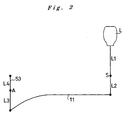
- FIG. 2 is a schematic diagram describing a system that transmits the operational force applied on the change-lever.
- FIG. 3 is a sectional plan view showing components of the system that transmits the operational force in a manual transmission equipped with a gear-shifting device according to the present invention.
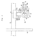
- FIG. 4 is a view showing parts of the gear-shifting device and parts surrounding the device.
- FIGS. 5A, 5B, 5C and 5D are step-by-step views showing chronologically the rotation of the shift arm during the shift operation, which arm is provided in the gear-shifting device.
- FIG. 6 is a graph describing a relation between the stroke of the synchro-sleeve and that of the change-lever, which strokes are observed during the shift operation in the gear-shifting device according to the present invention.
- FIG. 7 is a graph describing a relation between the stroke of the synchro-sleeve and that of the change-lever, which strokes are observed during the shift operation in a prior-art gear-shifting device.
- Now, a preferred embodiment of gear-shifting device for a manual transmission according to the present invention is described in reference to FIGS. 1~7.
- This manual transmission, when its Low, 2nd ~ 5th or Reverse clutch is selectively engaged, transmits the driving force of an engine selectively through a gear train with a different speed change ratio. For a gear shift, the driver manually operates the change-lever L provided at the driver seat. The following is a description of the mechanism to achieve a gear shift.
- The change-lever L, which is used to select one of the 1st ~ 5th speed change ratios and reverse ratio (hereinafter referred to as "R speed"), is operated in the patterns shown in FIG. 1. If the change-lever L is operated in the direction indicated by SE in the drawing, then it can be positioned at one of the three selecting positions: 1st-2nd speed selecting position X1, 3rd-4th speed selecting position X2, and 5th-R speed selecting position X3. Then, while the change-lever L is at the 1st-2nd speed selecting position X1, if it is shifted in the direction indicated by SH, which is perpendicular to the above mentioned operational direction SE, either the 1st speed position LOW or the 2nd speed position 2ND is selectable. Likewise, while the change-lever L is at the 3rd-4th speed selecting position X2, if it is shifted in the direction indicated by SH, either the 3rd speed position 3RD or the 4th speed position 4TH is selectable. Also, at the 5th-R speed selecting position X3, if the change-lever L is shifted in the direction indicated by SH, either the 5th speed position 5TH or the reverse position R is selectable.
- When the driver operates the change-lever L to any of the above mentioned speed change positions, the change-lever L swings around the position indicated by point S in FIG. 2 as fulcrum. As a result, the force applied on the change-lever L by the driver in the operation is transmitted through a
shift cable 11 to ashift arm 53, which rotates around its central axis A. Therefore, the system to transmit the operational force from the change-lever L to theshift arm 53 comprises a plurality of levers, which have leverages of L1/L2 and L3/L4, respectively, a shift arm 53 (the part indicated by L4), the above mentionedshift cable 11, and parts for connecting these components. - FIG. 3 shows the system that transmits the operational force (shifting force), which comprises the gear-shifting device according to the present invention. This operational
force transmitting system 30, which is provided in thetransmission case 21, comprises a 1st-2nd speedshift fork shaft 31, a 3rd-4th speed shift fork shaft 33 and a 5th-R speedshift fork shaft 35, which are movable longitudinally and axially. The 1st-2nd speedshift fork shaft 31 has detentgrooves 31a, which constitute adetent mechanism 32. By this mechanism, the 1st-2nd speedshift fork shaft 31 is positioned at any one of the three positions, LOW, Neutral, and 2ND. Likewise, the 3rd-4th speed shift fork shaft 33 and the 5th-R speedshift fork shaft 35 have detentgrooves 33a and 35a, respectively, which constitutedetent mechanisms 34 and 36, respectively. By these mechanisms, the 3rd-4th speed shift fork shaft 33 is positioned at any one of the three positions, 3RD, Neutral, and 4TH, and the 5th-R speedshift fork shaft 35 at either of the two positions, 5TH and Reverse (R), respectively. - Furthermore, the 1st-2nd speed
shift fork shaft 31, the 3rd-4th speed shift fork shaft 33 and the 5th-R speedshift fork shaft 35 are connected to a 1st-2ndspeed shift piece 41, a 3rd-4thspeed shift piece 43 and a 5th-Rspeed shift piece 45, respectively, which are supported in thetransmission case 21. Theseshift pieces shift fork shafts speed shift piece 43 because this drawing shows a condition that theshift pieces - Each
shift piece selector groove selector grooves shift arm 53, which will be described in detail later. When the change-lever L is swung in the SE direction shown in FIG. 1, eachselector groove shift arm 53. If the change-lever L is swung in the SH direction in FIG. 1, then theshift piece selector groove shift arm 53 is shifted with the correspondingshift fork shaft - The 1st-2nd speed
shift fork shaft 31, the 3rd-4th speed shift fork shaft 33 and the 5th-R speedshift fork shaft 35 are provided with a 1st-2ndspeed shift fork 61, a 3rd-4thspeed shift fork 63, and a 5th-Rspeed shift fork 65, respectively. The 1st-2ndspeed shift fork 61 is engaged with a 1st-2nd speed synchro-sleeve 71, which actuates a 1st clutch or a 2nd clutch (not shown). The 3rd-4thspeed shift fork 63 is engaged with a 3rd-4th speed synchro-sleeve 73, which actuates a 3rd clutch or a 4th clutch (not shown). The 5th-Rspeed shift fork 65 is engaged with a 5th-R speed synchro-sleeve 75, which actuates a 5th clutch or a reverse clutch (not shown). - With this arrangement, the appropriate operation of the change-lever L makes the
shift arm 53 to engage with any of theselector grooves speed shift piece 41, the 3rd-4thspeed shift piece 43 and the 5th-Rspeed shift piece 45 and then makes the engaged 1st-2nd speedshift fork shaft 31, 3rd-4th speed shift fork shaft 33 or 5th-R speedshift fork shaft 35 to shift in its axial direction. As a result, the 1st ~ 5th clutches and the reverse clutch are selectively actuated to establish the corresponding speed change ratios, LOW ~ R. - Now, in reference to FIG. 4, the gear-shifting device according to the present invention is described for a case where the operational force is transmitted from the
shift arm 53 to the 1st-2ndspeed shift fork 61 as an example. As shown in the drawing, the gear-shiftingdevice 50 comprises the above mentioned 1st-2ndspeed shift piece 41, ashift selector shaft 51, the above mentionedshift arm 53, and adetent mechanism 80. Theshift arm 53 is provided with circular holes, through which theshift selector shaft 51 is placed extending in the direction perpendicular to the paper carrying the drawing. Theshift arm 53 is fixed on theshift selector shaft 51 by abolt 54, which is screwed into a flank of theshift selector shaft 51. - The
shift selector shaft 51 shifts in the longitudinal axial direction (the direction perpendicular to the paper carrying the drawing), when the change-lever L is swung in the SE direction in FIG. 1 and rotates clockwise or counterclockwise around the axis A indicated in the drawing when the change-lever L is swung in the SH direction in FIG. 1. In other words, when the change-lever L is swung in the SE direction shown in FIG. 1, theshift arm 53 is shifted in the direction perpendicular to the paper. On the other hand, when the change-lever L is swung in the SH direction in FIG. 1, theshift arm 53 is rotated around the axis A. - As shown in FIG. 4, the
shift arm 53 at its neutral position is in contact with the 1st-2ndspeed shift piece 41 by the contactingpart 53c thereof. Therefore, when theshift arm 53 rotates around the axis A, the operational force is transmitted from theshift selector shaft 51 through the contactingpart 53c to the 1st-2ndspeed shift piece 41, shifting the 1st-2nd speedshift fork shaft 31 axially. Theshift arm 53 at its top part (where it engages with the 1st-2nd speed shift piece 41) has a compound arc figure (heteromorphous cams). In the neutral position shown in FIG. 4, thearc portion 53a (near the root of the protrusion) that is the closer of the arc portions to theshift selector shaft 51 is in contact with theshift piece 41 through the contactingpart 53c. However, if theshift arm 53 rotates around the axis A, the contactingpart 53c of theshift arm 53 in contact with theshift piece 41 shifts to thearc portion 53b (at the top of the protrusion) that is the closer of the arc portions to the 1st-2nd speedshift fork shaft 31, transmiting the operational force from the change-lever L to theshift piece 41. This will be described in detail later. - The top part of the
shift arm 53 is defined not by partially superimposing complete circles without any bias, but rather by partially cutting arcs so that the arcs have partially flattened sections. These partially flattened arcs are to maintain a clearance between theshift arm 53 and theshift piece 41 and yet to shift the 1st-2nd speedshift fork shaft 31 axially by a sufficient distance when theshift arm 53 rotates. - Furthermore, the
shift arm 53 is provided with adetent mechanism 80, which comprises aflanged retaining tube 81, aball 82, aspring 83, anddetent grooves tube 81 has an axis E that is perpendicular to the axis of theshift selector shaft 51. Theball 82 is held inside the retainingtube 81 so that it can move along the axis E of the retainingtube 81. Thespring 83 is also provided inside the retainingtube 81, so that it biases theball 82 toward theshift arm 53. The threedetent grooves shift arm 53 at even intervals, so each of them can engage individually with theball 82. - The
detent mechanism 80 defines angular positions (where theball 82 enters the right orleft detent groove shift arm 53, which is turned clockwise and counterclockwise from its neutral position (where theball 82 is in the detent groove 85) shown in FIG. 4. When theshift arm 53 is turned around the axis A for a predetermined angle counterclockwise (until theball 82 enters the detent groove 86) from the neutral position, the 1st-2nd speedshift fork shaft 31 is shifted leftward (with the 1st-2nd speed shift fork 61) in FIG. 4, engaging the 1st clutch. On the other hand, when theshift arm 53 is turned around the axis A for a predetermined angle clockwise (until theball 82 enters the detent groove 84) from the neutral position, the 1st-2nd speedshift fork shaft 31 is shifted rightward (with the 1st-2nd speed shift fork 61) in FIG. 4, engaging the 2nd clutch. - When the change-lever L is operated to the 2ND position, the
shift arm 53 is rotated to engage the 2nd clutch. Now, the movement of theshift arm 53 and the 1st-2ndspeed shift piece 41 being effected in this instance is described chronologically in reference to FIGS. 5A, 5B, 5C and 5D. - In the neutral position, as shown in FIG. 5A, the right and left
arc portions 53a of the top part of theshift arm 53, whicharc portions 53a are located closer to theshift selector shaft 51, are in contact with or in proximity to the right and left walls of the approximately U shapedselector groove 41a of theshift piece 41, at the contactingpart 53c of theshift arm 53. - When the driver starts to operate the change-lever L to the 2ND position, the
shift arm 53 starts to rotate clockwise around the axis A as shown in FIG. 5B. In this instance, the operational force applied at the change-lever L is transmitted to theshift piece 41 through the contactingpart 53c between theshift arm 53 and theshift piece 41, shifting theshift piece 41 rightward in the drawing. - When the change-lever L is operated further toward the 2ND position, increasing the displacement of the change-lever L, the
shift arm 53 rotates further clockwise from the condition shown in FIG. 5B to that shown in FIG. 5C. In this instance, the contactingpart 53c of the top part of theshift arm 53, which part is in contact with theshift piece 41, shifts to thearc portion 53b that is the farther of the arc portions from the rotational axis A of theshift arm 53. As a result, the operational force from the change-lever L is transmitted to theshift piece 41 through this new contactingpart 53c, which pushes the wall of theshift piece 41, shifting theshift piece 41 further rightward in the drawing. In the drawings, line B extends radially from the rotational axis A of theshift arm 53 through the center of the top part of theshift arm 53, and line C that extends through the contactingpart 53c and line D that extends through the rotational axis A are perpendicular to line B. Here, the length L4 (that corresponds to length L4 in FIG. 2) defined as the distance between line C and line D is longer in the condition shown in FIG. 5C than in FIG. 5B by the distance that the contactingpart 53c has shifted in this transition. - If the change-lever L is operated further to the 2ND position, then the
shift arm 53 rotates clockwise and stops at the predetermined angular position that is defined by thedetent mechanism 80 as shown in FIG. 5D. At this point, the displacement of the change-lever L has reached its maximum (full stroke). Correspondingly, the 1st-2nd speedshift fork shaft 31 has shifted by the predetermined distance axially, so the 1st-2ndspeed shift fork 61, which is mounted on the 1st-2nd speedshift fork shaft 31, engages with the 1st-2nd speed synchro-sleeve 71, which engages the 2nd clutch. - Here, the leverage (lever ratio) R from the change-lever L to the
shift arm 53 for the change-lever L to rotate theshift arm 53 is described as follows by using the lengths L1 ~ L4 shown in FIG. 2.
- In this equation, only length L4 is a variable, which changes during the period from the start to the completion of a shift operation, and the others L1 ~ L3 are constants. Therefore, the leverage R varies in dependence only on length L4 during the shift operation. While the leverage R is relatively high, the force required for the operation of the change-lever L is inversely small, reducing the burden of the driver. However, the displacement of the shift piece 41 (and the synchro-sleeve 71) also becomes inversely small.
- FIG. 6 describes how the leverage (lever ratio) R changes while the operational force is being transmitted from the
shift arm 53 to the 1st-2ndspeed shift fork 61 as the shift operation progresses with the driver's operation of the change-lever L. In this graph, the horizontal axis represents the displacement of the synchro-sleeve 71 while the vertical axis represents the displacement of the change-lever L, which is operated by the driver to actuate the synchro-sleeve 71. The leverage R is represented by the slant line in the graph. - In the condition shown in FIG. 5B (where the
arc portion 53a is in contact), length L4 is comparatively short, so the leverage R is large. Therefore, the inclination of the line that represents the relation between the displacement of the synchro-sleeve 71 and that of the change-lever L shown in FIG. 6 is comparatively large. On the other hand, when the contactingpart 53c between the top part of theshift arm 53 and theshift piece 41 shifts fromarc portion 53a toarc portion 53b, the inclination of the line shown in FIG. 6 becomes smaller. - As shown in FIG. 6, the point where the change of the leverage R occurs is set to come after the point of the synchronization of the synchro-
sleeve 71, which has shifted for an actuation. This point of the synchronization indicates the position in the stroke of the synchro-sleeve 71 where the synchromesh mechanism is actuated to push the corresponding gear for a gear shift, generating a friction for the synchronization. As shown in the graph, the leverage R at the synchronization point is comparatively large. Therefore, it is enough to apply a relatively small force at the change-lever L to achieve a relatively large force acting on the 1st-2ndspeed shift fork 61 for generating a friction for the synchronization by the synchromesh mechanism. - After the completion of the synchronization by the synchromesh mechanism, such a large force acting on the synchro-
sleeve 71 is no longer needed, but only a comparatively small force is needed to further shift the synchro-sleeve 71. For this reason, the leverage changes to a small value before the further displacement of the change-lever L is made. Because of this decreased leverage, the relatively short displacement of the change-lever L thereafter for the completion of the stroke achieves a sufficient displacement of the synchro-sleeve 71 to effect a gear shift. In this way, the stroke of the change-lever L required for a gear shift in the gear-shifting device according to the present invention can be made equal to that of a prior-art gear-shifting device. - As a contrast to what is described in FIG. 6, FIG. 7 shows a relation between the stroke of the synchro-sleeve and that of the change-lever observed during the operation of the change-lever in a prior-art gear-shifting device, which is equipped with a conventional shift arm. In this case, the leverage is invariable throughout the operation of the change-lever without any consideration of the passing of the synchro-sleeve over the synchronization point, so the inclination of the line in the graph is constant.
- The above embodiment according to the present invention is an example in which the top part of the shift arm is designed to change the leverage of the shift operation between two values. However, the present invention is not limited to this. Of course, the shift arm may be designed to vary the leverage among three values.
- As described above, in the gear-shifting device according to the present invention, the top part of the shift arm, which engages with a shift piece to shift a corresponding shift fork shaft with a shift fork, is designed to have a compound arc figure, which comprises a plurality of combined arcs having different curvature radii. By this arrangement, the leverage of the device from the change-lever to the shift fork is variable while the change-lever is being operated to rotate the shift arm for shifting the shift fork.
- As a result, a relatively large leverage available in the initial stage of the operation of the change-lever makes a relatively small force applied by the driver for a gear shift act on the shift fork as a large force. This ensures the synchronization of the synchromesh mechanism. On the other hand, during the shift operation of the driver, the leverage changes to a lower value at the completion of the synchronization, so the relatively short displacement of the change-lever L thereafter for the completion of the stroke achieves a sufficient displacement for the shift fork to complete the actuation. Therefore, the stroke of the change-lever in the gear-shifting device according to the present invention is still made equal to that of a prior-art gear-shifting device, so the present invention does not require an increase in the installation space of the change-lever in the interior of the vehicle.
- In addition, it is preferable that the point where the leverage changes from a larger value to a smaller value be set after the point of the synchronization of the synchromesh mechanism. In this way, the rate of the displacement of the shift fork to that of the change-lever is increased after the synchronization so as to quickly bring the gear into engagement. As a result, the reaction that is generated at the time of the gear meshing in the synchromesh mechanism is reduced in frequency and in magnitude. This is an advantage because the reaction is generally referred to as "two-step engaging load", which is uncomfortable to the driver, who is operating the change-lever.
Claims (6)
- A gear-shifting device for a manual transmission in which an operational force applied at a change-lever for a shift operation is transmitted selectively to actuate a synchro-sleeve for a gear shift;
wherein:said gear-shifting device comprises a shift arm, which is rotatable in correspondence to said shift operation of said change-lever, and a shift piece, which is in contact with said shift arm and is capable of shifting in response to said rotation of said shift arm;said shift arm has heteromorphous cams at its contacting part, which is in contact with said shift piece; andwhile said shift arm is rotating in correspondence to said shift operation, a distance between said contacting part and a rotational axis of said shift arm varies to change a leverage effective between said change-lever and said contacting part. - The gear-shifting device for a manual transmission, as set forth in claim 1, wherein:while said change-lever is being operated from a neutral position to a geared position, said leverage becomes smaller halfway through the operation.
- The gear-shifting device for a manual transmission, as set forth in claim 1 or 2, wherein:said manual transmission comprises a plurality of speed-change gears and a synchromesh mechanism, which synchronizes said synchro-sleeve and one of said speed-change gears by pushing said synchro-sleeve onto said speed-change gear; andsaid leverage is maximum at a time of synchronization by said synchromesh mechanism.
- The gear-shifting device for a manual transmission, as set forth in claim 3, wherein:said heteromorphous cams have a compound arc figure, which comprises a plurality of combined arcs having different curvature radii; andsaid leverage changes to a smaller value when said contacting part transits from a surface defined by one arc to a surface defined by another arc among said arcs in response to the rotation of said shift arm after the synchronization.
- The gear-shifting device as set forth in any of claims 1 ~ 4, wherein:said shift piece is provided with an approximately U shaped selector groove; andsaid contacting part of said shift arm is fitted in said selector groove.
- The gear-shifting device as set forth in any of claims 1 ~ 5, wherein:said shift arm is mounted on a shift selector shaft, which is rotated in correspondence to the shift operation of said change-lever.
Applications Claiming Priority (2)
| Application Number | Priority Date | Filing Date | Title |
|---|---|---|---|
| JP2003190153A JP4399197B2 (en) | 2003-07-02 | 2003-07-02 | Shift change device for manual transmission |
| PCT/JP2004/009387 WO2005003602A1 (en) | 2003-07-02 | 2004-06-25 | Gear shift device of manual transmission |
Publications (3)
| Publication Number | Publication Date |
|---|---|
| EP1653126A1 true EP1653126A1 (en) | 2006-05-03 |
| EP1653126A4 EP1653126A4 (en) | 2010-12-08 |
| EP1653126B1 EP1653126B1 (en) | 2012-12-12 |
Family
ID=33562321
Family Applications (1)
| Application Number | Title | Priority Date | Filing Date |
|---|---|---|---|
| EP04746856A Expired - Lifetime EP1653126B1 (en) | 2003-07-02 | 2004-06-25 | Gear shift device of manual transmission |
Country Status (6)
| Country | Link |
|---|---|
| US (1) | US7597024B2 (en) |
| EP (1) | EP1653126B1 (en) |
| JP (1) | JP4399197B2 (en) |
| CN (1) | CN100417844C (en) |
| TW (1) | TWI328659B (en) |
| WO (1) | WO2005003602A1 (en) |
Cited By (1)
| Publication number | Priority date | Publication date | Assignee | Title |
|---|---|---|---|---|
| EP1701068A3 (en) * | 2005-03-11 | 2008-06-04 | Zf Friedrichshafen Ag | Shift device for motor vehicle transmission |
Families Citing this family (24)
| Publication number | Priority date | Publication date | Assignee | Title |
|---|---|---|---|---|
| FR2888303A1 (en) * | 2005-07-05 | 2007-01-12 | Renault Sas | LOCKING DEVICE AND PARALLEL SHAFT GEARBOX |
| JP4701957B2 (en) * | 2005-09-22 | 2011-06-15 | トヨタ自動車株式会社 | Shift end determination device |
| KR100716554B1 (en) | 2005-11-15 | 2007-05-09 | 다이모스(주) | Manual mechanism |
| KR100680839B1 (en) | 2005-11-29 | 2007-02-08 | 현대자동차주식회사 | Manual transmission |
| DE102006023527A1 (en) * | 2006-05-19 | 2007-11-22 | Zf Friedrichshafen Ag | Switching device for a manual transmission of a motor vehicle |
| WO2008027054A1 (en) * | 2006-09-01 | 2008-03-06 | Mack Trucks, Inc. | Manual transmission with a gearshift locking arrangement and method |
| JP2009144877A (en) * | 2007-12-18 | 2009-07-02 | Daihatsu Motor Co Ltd | Selective sliding type reverse gearshift device |
| JP5064308B2 (en) * | 2008-06-09 | 2012-10-31 | アイシン・エーアイ株式会社 | Manual transmission operating device |
| JP2009293775A (en) * | 2008-06-09 | 2009-12-17 | Aisin Ai Co Ltd | Operating device for manual transmission |
| JP2009299809A (en) * | 2008-06-13 | 2009-12-24 | Honda Motor Co Ltd | Shift change device for manual transmission |
| DE102009000714A1 (en) * | 2009-02-09 | 2010-08-12 | Zf Friedrichshafen Ag | Switching device for a transmission of a motor vehicle |
| CN101648518B (en) * | 2009-09-16 | 2013-01-02 | 重庆蓝黛动力传动机械股份有限公司 | Speed changer of electric car |
| DE102009047715A1 (en) * | 2009-12-09 | 2011-06-16 | Zf Friedrichshafen Ag | Monorail switching device |
| DE102010009338A1 (en) * | 2010-02-25 | 2011-08-25 | WABCO GmbH, 30453 | transmission actuator |
| KR101553218B1 (en) * | 2010-04-06 | 2015-09-15 | 콩스베르그 오토모티브 아베 | Shift fork assembly |
| DE102010018094A1 (en) * | 2010-04-24 | 2011-10-27 | Gm Global Technology Operations Llc (N.D.Ges.D. Staates Delaware) | Gear change device for gear box of motor car, has shift fork mechanically decoupled from synchronous sleeve by locking finger after self-locking intervention of synchronous clutch toothed ring into synchronous toothed ring |
| KR20130017724A (en) * | 2011-08-11 | 2013-02-20 | 현대자동차주식회사 | Operating shift apparatus for transmission |
| US9371907B2 (en) * | 2012-12-13 | 2016-06-21 | Eaton Corporation | Shift rail inhibitor mechansim for a transmission |
| US9222574B2 (en) * | 2013-03-20 | 2015-12-29 | Gm Global Technology Operations, Llc | Cantilever spring type detent assembly |
| DE102014220429A1 (en) * | 2014-10-09 | 2016-04-28 | Zf Friedrichshafen Ag | Switching unit for an automated vehicle transmission with a plurality of partial transmissions with locking device |
| KR101637693B1 (en) * | 2014-10-15 | 2016-07-08 | 현대자동차주식회사 | Shifting apparatus for manual transmission |
| KR101941567B1 (en) * | 2017-05-18 | 2019-01-24 | 경창산업주식회사 | Detent Device For Manual Transmission |
| KR102389133B1 (en) * | 2017-09-12 | 2022-04-21 | 현대자동차주식회사 | Shift operating apparatus for transmission of vehicle |
| CN113531118A (en) * | 2020-04-17 | 2021-10-22 | 浙江万里扬股份有限公司 | Gear shifting assembly, gear shifting box and vehicle |
Family Cites Families (17)
| Publication number | Priority date | Publication date | Assignee | Title |
|---|---|---|---|---|
| GB775138A (en) * | 1954-03-12 | 1957-05-22 | Jaromir Vackar | A gear changing arrangement for gear boxes of motor vehicles |
| FR1474977A (en) * | 1966-02-16 | 1967-03-31 | Saviem | Advanced selection and control device for gearboxes |
| JPS6131743A (en) * | 1984-07-20 | 1986-02-14 | Suzuki Motor Co Ltd | Transmission for compact vehicle |
| DE3605015A1 (en) * | 1985-02-28 | 1986-09-04 | Zahnradfabrik Friedrichshafen Ag, 7990 Friedrichshafen | Gear change device |
| JP2968275B2 (en) | 1989-03-10 | 1999-10-25 | ヤマハ発動機株式会社 | Cam engagement part structure of transmission |
| JPH03130467A (en) | 1989-07-21 | 1991-06-04 | Ain:Kk | Fabric product prepared by covering cotton having deodorizing, germicidal, far infrared ray emitting and antistatic property with fabric body such as woven or nonwoven fabric |
| JP2876412B2 (en) | 1989-10-17 | 1999-03-31 | 日立電子エンジニアリング株式会社 | Recording media library device |
| JPH081325Y2 (en) * | 1990-04-11 | 1996-01-17 | マツダ株式会社 | Gear type transmission |
| JPH03130956U (en) * | 1990-04-16 | 1991-12-27 | ||
| DE4223409A1 (en) * | 1992-07-16 | 1992-11-26 | Zahnradfabrik Friedrichshafen | Gear change mechanism for gearbox - has lever with outer end formed by logarithmic spirals to eliminate play |
| US5450767A (en) * | 1993-11-03 | 1995-09-19 | Dana Corporation | Vehicle transmission having manually shifted lower gears and automatically shifted higher gears |
| JPH08326913A (en) | 1995-05-29 | 1996-12-10 | Suzuki Motor Corp | Reverse gear squeal prevention device |
| JP2000018381A (en) | 1998-07-01 | 2000-01-18 | Suzuki Motor Corp | Reverse gear squeal prevention device |
| JP3689287B2 (en) * | 1999-10-18 | 2005-08-31 | 本田技研工業株式会社 | Transmission gearbox |
| US6467598B2 (en) * | 1999-12-08 | 2002-10-22 | Eaton Corporation | Synchronizer |
| JP4511708B2 (en) * | 2000-09-29 | 2010-07-28 | 本田技研工業株式会社 | Continuously variable transmission |
| JP3980846B2 (en) | 2001-06-29 | 2007-09-26 | 本田技研工業株式会社 | Manual transmission change device |
-
2003
- 2003-07-02 JP JP2003190153A patent/JP4399197B2/en not_active Expired - Fee Related
-
2004
- 2004-06-25 WO PCT/JP2004/009387 patent/WO2005003602A1/en not_active Ceased
- 2004-06-25 EP EP04746856A patent/EP1653126B1/en not_active Expired - Lifetime
- 2004-06-25 CN CNB2004800187972A patent/CN100417844C/en not_active Expired - Fee Related
- 2004-06-25 US US10/562,482 patent/US7597024B2/en not_active Expired - Lifetime
- 2004-07-02 TW TW093120112A patent/TWI328659B/en not_active IP Right Cessation
Cited By (1)
| Publication number | Priority date | Publication date | Assignee | Title |
|---|---|---|---|---|
| EP1701068A3 (en) * | 2005-03-11 | 2008-06-04 | Zf Friedrichshafen Ag | Shift device for motor vehicle transmission |
Also Published As
| Publication number | Publication date |
|---|---|
| WO2005003602A1 (en) | 2005-01-13 |
| TWI328659B (en) | 2010-08-11 |
| US7597024B2 (en) | 2009-10-06 |
| US20060169083A1 (en) | 2006-08-03 |
| EP1653126B1 (en) | 2012-12-12 |
| TW200502499A (en) | 2005-01-16 |
| JP4399197B2 (en) | 2010-01-13 |
| CN1816708A (en) | 2006-08-09 |
| JP2005024007A (en) | 2005-01-27 |
| CN100417844C (en) | 2008-09-10 |
| EP1653126A4 (en) | 2010-12-08 |
Similar Documents
| Publication | Publication Date | Title |
|---|---|---|
| EP1653126B1 (en) | Gear shift device of manual transmission | |
| EP2028396B1 (en) | Transmission | |
| US7661331B2 (en) | Shifting device for dual clutch transmission | |
| EP2003374A2 (en) | Transmission | |
| US7426882B2 (en) | Gear-shifting device for manual transmission | |
| EP2180213A1 (en) | Manual transmission | |
| US4307624A (en) | Transmission gear selector arm and sleeves for shifting forks | |
| EP0786610A2 (en) | Shift device for a manual transmission | |
| EP2000707B1 (en) | Transmission | |
| EP1855032B1 (en) | Control assembly for a longitudinal gearbox | |
| US5966990A (en) | Shifting arrangement for, and method of shifting, a manual transmission | |
| CN107620795B (en) | Gearshift | |
| GB2325714A (en) | Device for operating a selector shaft of a shift transmission | |
| JP2696630B2 (en) | Gear noise prevention mechanism of manual transmission | |
| EP3805614B1 (en) | Gear shift operation device for vehicle, automatic transmission and method of controlling gear shift operation device | |
| KR102498154B1 (en) | Automotive transmission | |
| JP2006250358A (en) | Selector for automobile transmission | |
| KR20230011670A (en) | Shift operating apparatus for manual transmission | |
| KR100323416B1 (en) | Device for settling select position of manual transmission | |
| JP2001146965A (en) | Parking lock structure of semi-automatic transmission | |
| US20210285522A1 (en) | Manual dual clutch power transmission unit for a vehicle | |
| WO2011013043A1 (en) | A gearbox for motor vehicles | |
| EP0685667B1 (en) | Gear selector mechanism for transmission | |
| JP2005147342A (en) | Manual transmission reverse shift mechanism | |
| JP2009174684A (en) | Operation limiter for synchronization device of manual transmission |
Legal Events
| Date | Code | Title | Description |
|---|---|---|---|
| PUAI | Public reference made under article 153(3) epc to a published international application that has entered the european phase |
Free format text: ORIGINAL CODE: 0009012 |
|
| 17P | Request for examination filed |
Effective date: 20060131 |
|
| AK | Designated contracting states |
Kind code of ref document: A1 Designated state(s): DE FR GB |
|
| DAX | Request for extension of the european patent (deleted) | ||
| RBV | Designated contracting states (corrected) |
Designated state(s): DE FR GB |
|
| A4 | Supplementary search report drawn up and despatched |
Effective date: 20101105 |
|
| 17Q | First examination report despatched |
Effective date: 20110708 |
|
| REG | Reference to a national code |
Ref country code: DE Ref legal event code: R079 Ref document number: 602004040398 Country of ref document: DE Free format text: PREVIOUS MAIN CLASS: F16H0061320000 Ipc: F16H0063200000 |
|
| GRAP | Despatch of communication of intention to grant a patent |
Free format text: ORIGINAL CODE: EPIDOSNIGR1 |
|
| RIC1 | Information provided on ipc code assigned before grant |
Ipc: F16H 63/20 20060101AFI20120605BHEP Ipc: F16H 63/30 20060101ALI20120605BHEP |
|
| GRAS | Grant fee paid |
Free format text: ORIGINAL CODE: EPIDOSNIGR3 |
|
| GRAA | (expected) grant |
Free format text: ORIGINAL CODE: 0009210 |
|
| AK | Designated contracting states |
Kind code of ref document: B1 Designated state(s): DE FR GB |
|
| REG | Reference to a national code |
Ref country code: GB Ref legal event code: FG4D |
|
| RIN1 | Information on inventor provided before grant (corrected) |
Inventor name: MATSUDA, KENJI C/O KABUSHIKI KAISHA HONDA GIJUTS |
|
| REG | Reference to a national code |
Ref country code: DE Ref legal event code: R096 Ref document number: 602004040398 Country of ref document: DE Effective date: 20130207 |
|
| PGFP | Annual fee paid to national office [announced via postgrant information from national office to epo] |
Ref country code: GB Payment date: 20130610 Year of fee payment: 10 |
|
| PLBE | No opposition filed within time limit |
Free format text: ORIGINAL CODE: 0009261 |
|
| STAA | Information on the status of an ep patent application or granted ep patent |
Free format text: STATUS: NO OPPOSITION FILED WITHIN TIME LIMIT |
|
| 26N | No opposition filed |
Effective date: 20130913 |
|
| PGFP | Annual fee paid to national office [announced via postgrant information from national office to epo] |
Ref country code: FR Payment date: 20130726 Year of fee payment: 10 |
|
| REG | Reference to a national code |
Ref country code: DE Ref legal event code: R097 Ref document number: 602004040398 Country of ref document: DE Effective date: 20130913 |
|
| REG | Reference to a national code |
Ref country code: DE Ref legal event code: R084 Ref document number: 602004040398 Country of ref document: DE Effective date: 20140204 |
|
| GBPC | Gb: european patent ceased through non-payment of renewal fee |
Effective date: 20140625 |
|
| REG | Reference to a national code |
Ref country code: FR Ref legal event code: ST Effective date: 20150227 |
|
| PG25 | Lapsed in a contracting state [announced via postgrant information from national office to epo] |
Ref country code: FR Free format text: LAPSE BECAUSE OF NON-PAYMENT OF DUE FEES Effective date: 20140630 Ref country code: GB Free format text: LAPSE BECAUSE OF NON-PAYMENT OF DUE FEES Effective date: 20140625 |
|
| PGFP | Annual fee paid to national office [announced via postgrant information from national office to epo] |
Ref country code: DE Payment date: 20180612 Year of fee payment: 15 |
|
| REG | Reference to a national code |
Ref country code: DE Ref legal event code: R119 Ref document number: 602004040398 Country of ref document: DE |
|
| PG25 | Lapsed in a contracting state [announced via postgrant information from national office to epo] |
Ref country code: DE Free format text: LAPSE BECAUSE OF NON-PAYMENT OF DUE FEES Effective date: 20200101 |