EP1652716A2 - Hybrid car and control method for the same - Google Patents
Hybrid car and control method for the same Download PDFInfo
- Publication number
- EP1652716A2 EP1652716A2 EP05005269A EP05005269A EP1652716A2 EP 1652716 A2 EP1652716 A2 EP 1652716A2 EP 05005269 A EP05005269 A EP 05005269A EP 05005269 A EP05005269 A EP 05005269A EP 1652716 A2 EP1652716 A2 EP 1652716A2
- Authority
- EP
- European Patent Office
- Prior art keywords
- power
- engine
- wheels
- supercharger
- motor
- Prior art date
- Legal status (The legal status is an assumption and is not a legal conclusion. Google has not performed a legal analysis and makes no representation as to the accuracy of the status listed.)
- Granted
Links
Images




Classifications
-
- B—PERFORMING OPERATIONS; TRANSPORTING
- B60—VEHICLES IN GENERAL
- B60W—CONJOINT CONTROL OF VEHICLE SUB-UNITS OF DIFFERENT TYPE OR DIFFERENT FUNCTION; CONTROL SYSTEMS SPECIALLY ADAPTED FOR HYBRID VEHICLES; ROAD VEHICLE DRIVE CONTROL SYSTEMS FOR PURPOSES NOT RELATED TO THE CONTROL OF A PARTICULAR SUB-UNIT
- B60W20/00—Control systems specially adapted for hybrid vehicles
- B60W20/10—Controlling the power contribution of each of the prime movers to meet required power demand
-
- B—PERFORMING OPERATIONS; TRANSPORTING
- B60—VEHICLES IN GENERAL
- B60K—ARRANGEMENT OR MOUNTING OF PROPULSION UNITS OR OF TRANSMISSIONS IN VEHICLES; ARRANGEMENT OR MOUNTING OF PLURAL DIVERSE PRIME-MOVERS IN VEHICLES; AUXILIARY DRIVES FOR VEHICLES; INSTRUMENTATION OR DASHBOARDS FOR VEHICLES; ARRANGEMENTS IN CONNECTION WITH COOLING, AIR INTAKE, GAS EXHAUST OR FUEL SUPPLY OF PROPULSION UNITS IN VEHICLES
- B60K13/00—Arrangement in connection with combustion air intake or gas exhaust of propulsion units
- B60K13/02—Arrangement in connection with combustion air intake or gas exhaust of propulsion units concerning intake
-
- B—PERFORMING OPERATIONS; TRANSPORTING
- B60—VEHICLES IN GENERAL
- B60K—ARRANGEMENT OR MOUNTING OF PROPULSION UNITS OR OF TRANSMISSIONS IN VEHICLES; ARRANGEMENT OR MOUNTING OF PLURAL DIVERSE PRIME-MOVERS IN VEHICLES; AUXILIARY DRIVES FOR VEHICLES; INSTRUMENTATION OR DASHBOARDS FOR VEHICLES; ARRANGEMENTS IN CONNECTION WITH COOLING, AIR INTAKE, GAS EXHAUST OR FUEL SUPPLY OF PROPULSION UNITS IN VEHICLES
- B60K6/00—Arrangement or mounting of plural diverse prime-movers for mutual or common propulsion, e.g. hybrid propulsion systems comprising electric motors and internal combustion engines
- B60K6/20—Arrangement or mounting of plural diverse prime-movers for mutual or common propulsion, e.g. hybrid propulsion systems comprising electric motors and internal combustion engines the prime-movers consisting of electric motors and internal combustion engines, e.g. HEVs
- B60K6/22—Arrangement or mounting of plural diverse prime-movers for mutual or common propulsion, e.g. hybrid propulsion systems comprising electric motors and internal combustion engines the prime-movers consisting of electric motors and internal combustion engines, e.g. HEVs characterised by apparatus, components or means specially adapted for HEVs
- B60K6/24—Arrangement or mounting of plural diverse prime-movers for mutual or common propulsion, e.g. hybrid propulsion systems comprising electric motors and internal combustion engines the prime-movers consisting of electric motors and internal combustion engines, e.g. HEVs characterised by apparatus, components or means specially adapted for HEVs characterised by the combustion engines
-
- B—PERFORMING OPERATIONS; TRANSPORTING
- B60—VEHICLES IN GENERAL
- B60K—ARRANGEMENT OR MOUNTING OF PROPULSION UNITS OR OF TRANSMISSIONS IN VEHICLES; ARRANGEMENT OR MOUNTING OF PLURAL DIVERSE PRIME-MOVERS IN VEHICLES; AUXILIARY DRIVES FOR VEHICLES; INSTRUMENTATION OR DASHBOARDS FOR VEHICLES; ARRANGEMENTS IN CONNECTION WITH COOLING, AIR INTAKE, GAS EXHAUST OR FUEL SUPPLY OF PROPULSION UNITS IN VEHICLES
- B60K6/00—Arrangement or mounting of plural diverse prime-movers for mutual or common propulsion, e.g. hybrid propulsion systems comprising electric motors and internal combustion engines
- B60K6/20—Arrangement or mounting of plural diverse prime-movers for mutual or common propulsion, e.g. hybrid propulsion systems comprising electric motors and internal combustion engines the prime-movers consisting of electric motors and internal combustion engines, e.g. HEVs
- B60K6/42—Arrangement or mounting of plural diverse prime-movers for mutual or common propulsion, e.g. hybrid propulsion systems comprising electric motors and internal combustion engines the prime-movers consisting of electric motors and internal combustion engines, e.g. HEVs characterised by the architecture of the hybrid electric vehicle
- B60K6/44—Series-parallel type
-
- B—PERFORMING OPERATIONS; TRANSPORTING
- B60—VEHICLES IN GENERAL
- B60K—ARRANGEMENT OR MOUNTING OF PROPULSION UNITS OR OF TRANSMISSIONS IN VEHICLES; ARRANGEMENT OR MOUNTING OF PLURAL DIVERSE PRIME-MOVERS IN VEHICLES; AUXILIARY DRIVES FOR VEHICLES; INSTRUMENTATION OR DASHBOARDS FOR VEHICLES; ARRANGEMENTS IN CONNECTION WITH COOLING, AIR INTAKE, GAS EXHAUST OR FUEL SUPPLY OF PROPULSION UNITS IN VEHICLES
- B60K6/00—Arrangement or mounting of plural diverse prime-movers for mutual or common propulsion, e.g. hybrid propulsion systems comprising electric motors and internal combustion engines
- B60K6/20—Arrangement or mounting of plural diverse prime-movers for mutual or common propulsion, e.g. hybrid propulsion systems comprising electric motors and internal combustion engines the prime-movers consisting of electric motors and internal combustion engines, e.g. HEVs
- B60K6/50—Architecture of the driveline characterised by arrangement or kind of transmission units
- B60K6/52—Driving a plurality of drive axles, e.g. four-wheel drive
-
- B—PERFORMING OPERATIONS; TRANSPORTING
- B60—VEHICLES IN GENERAL
- B60W—CONJOINT CONTROL OF VEHICLE SUB-UNITS OF DIFFERENT TYPE OR DIFFERENT FUNCTION; CONTROL SYSTEMS SPECIALLY ADAPTED FOR HYBRID VEHICLES; ROAD VEHICLE DRIVE CONTROL SYSTEMS FOR PURPOSES NOT RELATED TO THE CONTROL OF A PARTICULAR SUB-UNIT
- B60W10/00—Conjoint control of vehicle sub-units of different type or different function
- B60W10/04—Conjoint control of vehicle sub-units of different type or different function including control of propulsion units
- B60W10/06—Conjoint control of vehicle sub-units of different type or different function including control of propulsion units including control of combustion engines
-
- B—PERFORMING OPERATIONS; TRANSPORTING
- B60—VEHICLES IN GENERAL
- B60W—CONJOINT CONTROL OF VEHICLE SUB-UNITS OF DIFFERENT TYPE OR DIFFERENT FUNCTION; CONTROL SYSTEMS SPECIALLY ADAPTED FOR HYBRID VEHICLES; ROAD VEHICLE DRIVE CONTROL SYSTEMS FOR PURPOSES NOT RELATED TO THE CONTROL OF A PARTICULAR SUB-UNIT
- B60W10/00—Conjoint control of vehicle sub-units of different type or different function
- B60W10/04—Conjoint control of vehicle sub-units of different type or different function including control of propulsion units
- B60W10/08—Conjoint control of vehicle sub-units of different type or different function including control of propulsion units including control of electric propulsion units, e.g. motors or generators
-
- B—PERFORMING OPERATIONS; TRANSPORTING
- B60—VEHICLES IN GENERAL
- B60W—CONJOINT CONTROL OF VEHICLE SUB-UNITS OF DIFFERENT TYPE OR DIFFERENT FUNCTION; CONTROL SYSTEMS SPECIALLY ADAPTED FOR HYBRID VEHICLES; ROAD VEHICLE DRIVE CONTROL SYSTEMS FOR PURPOSES NOT RELATED TO THE CONTROL OF A PARTICULAR SUB-UNIT
- B60W20/00—Control systems specially adapted for hybrid vehicles
-
- B—PERFORMING OPERATIONS; TRANSPORTING
- B60—VEHICLES IN GENERAL
- B60W—CONJOINT CONTROL OF VEHICLE SUB-UNITS OF DIFFERENT TYPE OR DIFFERENT FUNCTION; CONTROL SYSTEMS SPECIALLY ADAPTED FOR HYBRID VEHICLES; ROAD VEHICLE DRIVE CONTROL SYSTEMS FOR PURPOSES NOT RELATED TO THE CONTROL OF A PARTICULAR SUB-UNIT
- B60W30/00—Purposes of road vehicle drive control systems not related to the control of a particular sub-unit, e.g. of systems using conjoint control of vehicle sub-units
- B60W30/18—Propelling the vehicle
- B60W30/18172—Preventing, or responsive to skidding of wheels
-
- F—MECHANICAL ENGINEERING; LIGHTING; HEATING; WEAPONS; BLASTING
- F02—COMBUSTION ENGINES; HOT-GAS OR COMBUSTION-PRODUCT ENGINE PLANTS
- F02B—INTERNAL-COMBUSTION PISTON ENGINES; COMBUSTION ENGINES IN GENERAL
- F02B39/00—Component parts, details, or accessories relating to, driven charging or scavenging pumps, not provided for in groups F02B33/00 - F02B37/00
- F02B39/02—Drives of pumps; Varying pump drive gear ratio
- F02B39/08—Non-mechanical drives, e.g. fluid drives having variable gear ratio
- F02B39/10—Non-mechanical drives, e.g. fluid drives having variable gear ratio electric
-
- B—PERFORMING OPERATIONS; TRANSPORTING
- B60—VEHICLES IN GENERAL
- B60W—CONJOINT CONTROL OF VEHICLE SUB-UNITS OF DIFFERENT TYPE OR DIFFERENT FUNCTION; CONTROL SYSTEMS SPECIALLY ADAPTED FOR HYBRID VEHICLES; ROAD VEHICLE DRIVE CONTROL SYSTEMS FOR PURPOSES NOT RELATED TO THE CONTROL OF A PARTICULAR SUB-UNIT
- B60W2520/00—Input parameters relating to overall vehicle dynamics
- B60W2520/28—Wheel speed
-
- B—PERFORMING OPERATIONS; TRANSPORTING
- B60—VEHICLES IN GENERAL
- B60Y—INDEXING SCHEME RELATING TO ASPECTS CROSS-CUTTING VEHICLE TECHNOLOGY
- B60Y2400/00—Special features of vehicle units
- B60Y2400/43—Engines
- B60Y2400/435—Supercharger or turbochargers
-
- F—MECHANICAL ENGINEERING; LIGHTING; HEATING; WEAPONS; BLASTING
- F02—COMBUSTION ENGINES; HOT-GAS OR COMBUSTION-PRODUCT ENGINE PLANTS
- F02D—CONTROLLING COMBUSTION ENGINES
- F02D41/00—Electrical control of supply of combustible mixture or its constituents
- F02D41/0002—Controlling intake air
- F02D41/0007—Controlling intake air for control of turbo-charged or super-charged engines
-
- Y—GENERAL TAGGING OF NEW TECHNOLOGICAL DEVELOPMENTS; GENERAL TAGGING OF CROSS-SECTIONAL TECHNOLOGIES SPANNING OVER SEVERAL SECTIONS OF THE IPC; TECHNICAL SUBJECTS COVERED BY FORMER USPC CROSS-REFERENCE ART COLLECTIONS [XRACs] AND DIGESTS
- Y02—TECHNOLOGIES OR APPLICATIONS FOR MITIGATION OR ADAPTATION AGAINST CLIMATE CHANGE
- Y02T—CLIMATE CHANGE MITIGATION TECHNOLOGIES RELATED TO TRANSPORTATION
- Y02T10/00—Road transport of goods or passengers
- Y02T10/10—Internal combustion engine [ICE] based vehicles
- Y02T10/40—Engine management systems
-
- Y—GENERAL TAGGING OF NEW TECHNOLOGICAL DEVELOPMENTS; GENERAL TAGGING OF CROSS-SECTIONAL TECHNOLOGIES SPANNING OVER SEVERAL SECTIONS OF THE IPC; TECHNICAL SUBJECTS COVERED BY FORMER USPC CROSS-REFERENCE ART COLLECTIONS [XRACs] AND DIGESTS
- Y02—TECHNOLOGIES OR APPLICATIONS FOR MITIGATION OR ADAPTATION AGAINST CLIMATE CHANGE
- Y02T—CLIMATE CHANGE MITIGATION TECHNOLOGIES RELATED TO TRANSPORTATION
- Y02T10/00—Road transport of goods or passengers
- Y02T10/60—Other road transportation technologies with climate change mitigation effect
- Y02T10/62—Hybrid vehicles
-
- Y—GENERAL TAGGING OF NEW TECHNOLOGICAL DEVELOPMENTS; GENERAL TAGGING OF CROSS-SECTIONAL TECHNOLOGIES SPANNING OVER SEVERAL SECTIONS OF THE IPC; TECHNICAL SUBJECTS COVERED BY FORMER USPC CROSS-REFERENCE ART COLLECTIONS [XRACs] AND DIGESTS
- Y02—TECHNOLOGIES OR APPLICATIONS FOR MITIGATION OR ADAPTATION AGAINST CLIMATE CHANGE
- Y02T—CLIMATE CHANGE MITIGATION TECHNOLOGIES RELATED TO TRANSPORTATION
- Y02T10/00—Road transport of goods or passengers
- Y02T10/60—Other road transportation technologies with climate change mitigation effect
- Y02T10/7072—Electromobility specific charging systems or methods for batteries, ultracapacitors, supercapacitors or double-layer capacitors
-
- Y—GENERAL TAGGING OF NEW TECHNOLOGICAL DEVELOPMENTS; GENERAL TAGGING OF CROSS-SECTIONAL TECHNOLOGIES SPANNING OVER SEVERAL SECTIONS OF THE IPC; TECHNICAL SUBJECTS COVERED BY FORMER USPC CROSS-REFERENCE ART COLLECTIONS [XRACs] AND DIGESTS
- Y02—TECHNOLOGIES OR APPLICATIONS FOR MITIGATION OR ADAPTATION AGAINST CLIMATE CHANGE
- Y02T—CLIMATE CHANGE MITIGATION TECHNOLOGIES RELATED TO TRANSPORTATION
- Y02T10/00—Road transport of goods or passengers
- Y02T10/80—Technologies aiming to reduce greenhouse gasses emissions common to all road transportation technologies
- Y02T10/84—Data processing systems or methods, management, administration
-
- Y—GENERAL TAGGING OF NEW TECHNOLOGICAL DEVELOPMENTS; GENERAL TAGGING OF CROSS-SECTIONAL TECHNOLOGIES SPANNING OVER SEVERAL SECTIONS OF THE IPC; TECHNICAL SUBJECTS COVERED BY FORMER USPC CROSS-REFERENCE ART COLLECTIONS [XRACs] AND DIGESTS
- Y10—TECHNICAL SUBJECTS COVERED BY FORMER USPC
- Y10S—TECHNICAL SUBJECTS COVERED BY FORMER USPC CROSS-REFERENCE ART COLLECTIONS [XRACs] AND DIGESTS
- Y10S903/00—Hybrid electric vehicles, HEVS
- Y10S903/902—Prime movers comprising electrical and internal combustion motors
- Y10S903/903—Prime movers comprising electrical and internal combustion motors having energy storing means, e.g. battery, capacitor
- Y10S903/904—Component specially adapted for hev
- Y10S903/906—Motor or generator
Definitions
- the present invention relates to a hybrid car for driving either of front and rear wheels by an engine and driving the other wheels by a motor.
- Patent Document 1 Japanese Application Patent Laid-open Publication No. Hei 07-231508 describes a four-wheel driving device for converting power to electrical energy using an engine as a power source, driving a motor by the electrical energy, thereby driving either of front and rear wheels.
- Patent Document 2 Japanese Application Patent Laid-open Publication No. 2003-301725 discloses an invention for operating an exhaust turbo-rotary machine as a motor by generated power of a rotary machine connected to an engine power shaft, assisting turbo-supercharging, thereby increasing torque of the engine.
- the driving device for a hybrid vehicle disclosed in Patent Document 1 is said to be easily mountable due to a small battery. Such a device is considered to be suitable especially for a small car having a limited space.
- a small car generally loads a small engine, and the output of an engine, which can be used for power generation, is limited, so that motor output for sufficiently driving wheels can be hardly obtained, and there is the possibility that the acceleration and running property on a bad road such as a frozen road or a muddy road, which is required by four-wheel drive, cannot be obtained sufficiently.
- the efficiency of converting the mechanical energy from the engine to electrical energy by the generator and furthermore the efficiency of converting the electrical energy to the mechanical energy by the motor are concerned with it, so that a problem arises that the efficiency as a whole is reduced and the necessary output of the motor can be hardly obtained.
- An object of the present invention is to provide a hybrid vehicle capable of obtaining large acceleration in a satisfactory road surface state while stably ensuring the bad road running property and simultaneously in a case requiring no large acceleration, running with the fuel consumption kept unchanged.
- a further object of the present invention is to provide a method for accomplishing the first object and reducing vibration and noise generated from the generator and engine.
- a further object of the present invention is to provide a power distribution method by a distributor for accomplishing the first objed.
- the hybrid car of the present invention may run by driving at least one of front wheels, rear wheels and a generator by an engine, driving a wheel driving motor by power of the generator, andor driving wheels not driven by the engine controls distributon amounts according to the running state when distributing the power generated by the generator to a supercharger motor for driving a supercharger installed in an air intake pipe of the engine and the wheel driving motor.
- the hybrid car may include the engine for driving the front wheels and/or the rear wheels, the generator driven by the engine, the wheel driving motor for receiving the power generated by the generator and driving the wheels (referred to as engine non-driven wheels) not driven by the engine, the supercharger installed in the air intake pipe of the engine, the supercharger motor for receiving the power generated by the generator and driving the supercharger, and/or the power distributor for distributing the power from the generator to the supercharger motor and wheel driving motor.
- a control method for the power distributor of the present invention may switch the power faster than the response speed of a mechanical input change during a power load change of the generator.
- a control method for the power distributor of the present invention may adjust power distribution amounts to the supercharger motor and wheel driving motor by a switching operation of a car driver. Concretely, when the rotational speed of the wheels (referred to as engine driven wheels) driven by the engine exceeds the rotational speed of the engine non-driven wheels, the power distribution to the wheel driving motor is preferably increased.
- the control method is preferably a control method for a power distributor characterized in that the power distribution to the supercharger motor is increased.
- FIG. 1 shows a system configuration example of the hybrid car relating to the present invention.
- the vehicle includes an engine 1 for driving at least one of front wheels 2 and rear wheels 8, a generator 10 driven by the engine 1, a wheel driving motor 14 for driving wheels (referred to as engine non-driven wheels) not driven by the engine 1 upon receipt of power generated by the generator 10, a supercharger 1 a installed in an air intake pipe of the engine 1, a supercharger driving motor 1 b for driving the supercharger 1 a upon receipt of the power generated by the generator 10, and a power distributor 12 for distributing the power from the generator 10 to the supercharger motor 1 b and the wheel driving motor 14 and adjusting the distributed power quantities.
- the vehicle includes further wheel speed sensors 3a and 3b for detecting the rotation of each of wheels (referred to as engine driven wheels) driven by the engine 1 and wheels (referred to as motor driven wheels) driven by the motor, and a controller 7 for inputting information of the wheel speed sensors 3a and 3b and controlling the power distribution of the distributor 12.
- engine driven wheels driven by the engine 1
- motor driven wheels driven by the motor
- controller 7 for inputting information of the wheel speed sensors 3a and 3b and controlling the power distribution of the distributor 12.
- the output of the engine 1 is transferred to the front wheels 2 via a transmission 9 having a built-in torque converter.
- the output of the wheel driving motor 14 is transferred to the rear wheels 8 via a differential gear 15 having a built-in clutch.
- the generator 10, the wheel driving motor 14, and the supercharger driving motor 1 b are electrically connected by power lines 11 a, 11 b, and 11c via the power distributor 12.
- the generator 10 is driven by the engine 1 via a speeding-up pulley mechanism not shown in the drawing.
- the generated power can be changed by the field current flowing through a generator field coil 10a.
- the controller 7 to control the generated power, adjust the field current on the basis of the information of the current flowing through the power line 11a from a current sensor not shown in the drawing. Therefore, there is no need to arrange a particular circuit on the output side of the generator, thus lightweight can be realized.
- the currents of the respective built-in field coils 14a and 1d are controlled by the controller 7, so that the torque constant can be changed, and desired torque can be obtained, and additionally the power can be prevented from a reverse current to the generator by the counter electromotive force generated by the respective motors, and the generator can be prevented from burning.
- the controller 7 controls an electronic control throttle 1f for adjusting the intake air flow rate which is arranged in an air intake pipe 1 c of the engine 1, thereby controls the output of the engine. Further, the controller 7 monitors the engine speed using a signal from a rotational speed sensor 1e attached to the engine.
- an accelerator pedal sensor 5 for detecting the stepping depth on the accelerator of a driver is installed and a detection signal thereof is sent to the controller 7.
- the wheel speed sensors 3a to 3d are installed on the respective wheels and signals thereof are sent to the controller 7. Further, to the controller 7, a signal indicating the status of a switch 4 used to select the power distributor control operation by the driver is sent.
- Fig. 3 shows the switch 4 in detail.
- Fig. 3A is a front view of the switch and the driver rotates a knob 4a, thereby selects the control method for the power distributor.
- the fuel consumption saving priority mode is selected
- the position B is selected
- the high ⁇ road acceleration priority mode giving priority to the acceleration during running on a high ⁇ road
- the position C is selected
- the low ⁇ road acceleration and running property priority mode giving priority to the acceleration and running property on a low ⁇ road is selected.
- control methods selectable by one switch are put together like this, so that the selection is simple and the selected control method can be easily confirmed.
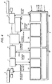
- Fig. 4 shows a function block diagram of the controller 7.
- a driver request judgment block B8 reads signals (information) from the selection switch 4 and the accelerator pedal sensor 5 and calculates drive torque requested by the driver.
- a vehicle driving method decision block B7 calculates the drive torques which are targets of the front and rear wheels, synthesizes them with information of the gear ratio from a transmission control block B1, information of the engine speed and torque from an engine output control block B2, information of the input torque and output power of the generator 10 from a generator output control block B3, information of power distribution to the motors 1 b and 14 from a distributor control block B4, information of the rotational speed of the supercharger 1 a from a supercharger driving motor control block B5, and information of the rotational speed and torque of the wheel driving motor 14 from a wheel driving motor control block B6, and transfers instruction values to the blocks B1 to B6.
- the transmission control block B on the basis of the instruction, selects the gear ratio and controls the lockup of the automatic transmission.
- the engine output control block B2 controls the fuel feed amount by a fuel injector not shown in the drawing and also controls the intake air amount using the electronic control throttle 1f and the ignition timing by an igniting device not shown in the drawing.
- the generator control block B3 uses information of a current sensor and a voltage sensor which are not shown in the drawing, adjusts the field current of the field coil 10a of the generator 10 along the target output.
- the distributor control block B4 to realize the decided power distribution, controls the switching operation on the basis of information of a current sensor and a voltage sensor not shown in the drawing which are installed between the power distributor 12 and each motor.
- the supercharger driving motor control block B5 and the wheel driving motor block B6 detect the rotational speed of each motor by a rotational speed sensor not shown in the drawing and on the basis of the detected values, control the currents of the field coils 1 d and 14a. Concretely, the blocks control the current using the PWM (pulse width modulation) by turning the voltage on or off.
- PWM pulse width modulation
- Fig. 5 shows the flow of decision of whether or not to control the supercharger driving motor 1 b and the wheel driving motor 14 and when the engine 1 is started by the driver request judgment block B8, the control is executed repeatedly.
- Step S1 when the accelerator pedal is stepped on the basis of a signal from the accelerator pedal sensor 5, it is assumed that an acceleration request is presented and the acceleration request is decided.
- Step S2 when the acceleration request is presented on the basis of the acceleration request decision, the process goes to Step S3, and when no acceleration request is presented, the process goes to Return.
- Step S3 the position of the switch 4 is read and the control mode according to the position is executed by the wheel driving method decision block B7.
- the controller 7 controls so as to avoid distribution of the power from the power distributor 12 to the supercharger driving motor 1 b and the wheel driving motor 14.
- Fig. 6 shows the flow when the switch 4 selects the high ⁇ road acceleration priority control mode at the position B.
- the power distribution of the power distributor 12 is made larger for the supercharger driving motor 1 b so as to increase the engine torque.
- Step S20 where the instruction value of the power distributor 12 is calculated, during continuation of the acceleration request, the power distribution to the supercharger driving motor 1 b is increased and furthermore, the engine torque is increased, thus large acceleration is controlled so as to obtain.
- Step S21 the difference between the speed of the front wheels 2 and the rotational speed of the rear wheels 8 is obtained by subtraction, and when the difference in the rotational speed is larger than a predetermined value, it is decided that an excessive slip is generated, and the process goes to Step S23 from Step S22, and to decrease the torque supply to the front wheels 2, Step S23 for operating the wheel driving motor 14 for driving the rear wheels 8 is executed.
- Fig. 7 shows the flow when the switch 4 selects the low ⁇ road acceleration and running property priority mode at the position C.
- Step S31 moves the process to Step S32 and the supply of the power to the wheel driving motor 14 is increased.
- Step S32 the power distribution to the wheel driving motor 14 is large originally, so that as a result of Step S32, there is the possibility that the rear wheels 8 driven by the motor 14 may slip.
- the slip of the rear wheels 8 is detected by a method for obtaining the acceleration on the basis of the wheel speed of the rear wheels 8 detected by the wheel speed sensors 3b and 3d and when it is larger than a preset threshold value, deciding that the wheels slip.
- Step S32 when the method is executed and the slip is excessive, the process goes to Step S36 from Step S35 to reduce the power to the rear wheel driving motor 14 and the power distribution to the supercharger motor 1b is increased.
- Step S35 When the rear wheels 8 do not slip, the process goes to Return from Step S35 straight.
- Step S30 When the decision result at Step S30 shows that the front wheels 2 do not slip excessively, the process goes to Step S33 form Step S31, and the distribution to the supercharger driving motor 1 b is increased, and the engine output is increased, thus the low ⁇ road acceleration and running property is increased more.
- Figs. 8 to 11 show schematically the operation of the power distributor 12.
- Fig. 8 is a drawing showing changes in the drive torque of the generator when changing the output of the generator 10 from the supercharger driving motor 1 b to the wheel driving motor 14 by the power distributor 12, that is, an example of mechanical response of the generator 10.
- the power distributor 12 starts switching at the time 0 and the drive torque of the generator 10 is changed late.
- the moment of switching is shown and 63% of the change of the drive torque is defined as a response time of ⁇ .
- Fig. 9 shows the input and output of the power distributor 12.
- the input is power from the generator 10, which is supplied by the power line 11 a.
- the output is composed of three ways, and the first way is connected to the supercharger driving motor 1 d via the power line 11 b, and the second way is connected to the wheel driving motor 14 via the power line 11 c, and the third way is connected to a resistor 51.
- the power distributor 12 switches and distributes the input power to the first to third outputs.
- Fig. 10 is a drawing showing a suitable operation status of the distributor 12 and the power supply timings to the wheel driving motor 14, the supercharger driving motor 1b, and the resistor 51 are shown respectively as A, B, and C.
- the drive torque of the generator 10 at that time is indicated as D and the generated power is indicated as E.
- Each dashed line indicates the time equivalent to the response time ⁇ .
- the power supply time is switched within the range of time shorter than the response time ⁇ indicated by the dashed line.
- the drive torque of the generator 10 changes little and simultaneously the generated power of the generator 10 changes little.
- the circuit of the distributor 12 is increased in price, so that here, the supply time is limited to the response time ⁇ capable of producing a sufficient effect.
- the drive torque of the generator 10 is changed greatly compared with a case (the dashed line in D) of power distribution at intervals shorter than the response time ⁇ , and deterioration of the durability of the belt of the pulley mechanism for driving the generator 10, noise, and vibration are caused, and the comfortableness to ride in is spoiled.
- the field coil 14a responds to power cut of the power distributor 12 late due to the coil inductance, so that when attempting to stop immediately the torque of the wheel driving motor 14, the power distributor 12 may be effectively used.
- the power distributor capable of actively distributing power as described in this embodiment can produce an effect of safety improvement.
- a hybrid car having the three ensured properties such as the fuel consumption saving property, acceleration and running property on a low ⁇ road, and acceleration on a high ⁇ road can be realized.
- the power distribution of the supercharger motor and wheel driving motor is made variable, when the output of the wheel driving motor is low, the power distribution to the supercharger motor can be reduced or stopped and even in a four-wheel driving state, an increase in fuel consumption can be suppressed.
- the power distribution to the wheel driving motor is reduced or stopped, and the engine torque is increased by distributing the generated power to the supercharger motor, and the acceleration property of the vehicle on a ⁇ road can be improved.
- the switching time is made shorter than the mechanical response speed of the generator, thus the mechanical input change of the generator is reduced, and the vibration of the engine and the mechanism connecting the generator and engine is reduced, and the comfortableness to ride in is improved, and the durability of the mechanism is improved.
- control suited to the acceleration and running property on a road easy to slip (low ⁇ road) such as a frozen road, a snow road, or a muddy road or the acceleration property and fuel consumption saving property on a high ⁇ road such as a dry asphalt road can be executed.
- the power is distributed to both the wheel driving motor and supercharger motor by the power distributor to drive the four wheels.
- the power is distributed to the supercharger motor in priority by the power distributor and the torque generated by the engine is mostly transferred to the wheels driven by the engine.
- the power distribution can be controlled by using the distributor so as to reduce the power to the supercharger motor and wheel driving motor from the power distributor. As a result, an effect of easily obtaining the expected vehicle performance of the driver can be produced.
- the wheels driven by the engine slip under the control by the distributor in a state that the output of the wheel driving motor is low, that is, when the rotational speed of the engine driven wheels is higher than the rotational speed of the other wheels, the power distribution to the wheel driving motor is increased by the power distributor, and the output of the supercharger driving motor is lowered, thus the engine output is reduced, and the slip of the engine driven wheels can be stopped immediately, and the deterioration of the acceleration property can be reduced.
- the motor driven wheels slip in the four-wheel driving state by controlling the power distribution sent to each motor by the power distributor, that is, when the rotational speed of the motor driven wheels is higher than the rotational speed of the engine driven wheels, the power distribution to the motors is distributed to the supercharger, thus the output of the motor is reduced, and the slip of the motor driven wheels is suppressed, and the acceleration and running property on the low ⁇ road can be maintained.
- the acceleration and running property on the low ⁇ road and the acceleration and running property on the high ⁇ road can be made consistent with each other.
Landscapes
- Engineering & Computer Science (AREA)
- Chemical & Material Sciences (AREA)
- Combustion & Propulsion (AREA)
- Mechanical Engineering (AREA)
- Transportation (AREA)
- Automation & Control Theory (AREA)
- General Engineering & Computer Science (AREA)
- Electric Propulsion And Braking For Vehicles (AREA)
- Hybrid Electric Vehicles (AREA)
- Control Of Vehicle Engines Or Engines For Specific Uses (AREA)
- Arrangement And Driving Of Transmission Devices (AREA)
- Supercharger (AREA)
Abstract
Description
- The present invention relates to a hybrid car for driving either of front and rear wheels by an engine and driving the other wheels by a motor.
- Patent Document 1 (Japanese Application Patent Laid-open Publication No. Hei 07-231508) describes a four-wheel driving device for converting power to electrical energy using an engine as a power source, driving a motor by the electrical energy, thereby driving either of front and rear wheels.
- Patent Document 2 (Japanese Application Patent Laid-open Publication No. 2003-301725) discloses an invention for operating an exhaust turbo-rotary machine as a motor by generated power of a rotary machine connected to an engine power shaft, assisting turbo-supercharging, thereby increasing torque of the engine.
- The driving device for a hybrid vehicle disclosed in
Patent Document 1 is said to be easily mountable due to a small battery. Such a device is considered to be suitable especially for a small car having a limited space. - On the other hand, a small car generally loads a small engine, and the output of an engine, which can be used for power generation, is limited, so that motor output for sufficiently driving wheels can be hardly obtained, and there is the possibility that the acceleration and running property on a bad road such as a frozen road or a muddy road, which is required by four-wheel drive, cannot be obtained sufficiently.
- Moreover, particularly when supplying power of a generator directly to the motor, the efficiency of converting the mechanical energy from the engine to electrical energy by the generator and furthermore the efficiency of converting the electrical energy to the mechanical energy by the motor are concerned with it, so that a problem arises that the efficiency as a whole is reduced and the necessary output of the motor can be hardly obtained.
- Therefore, it may be considered to temporarily supply power to the motor by using a battery. However, the stored electricity quantity of the battery is limited and there is the possibility that the acceleration and running property on a bad road cannot be maintained for many hours.
- Further, since the efficiency is low, when driving a wheel driving motor in a road surface state requiring no four-wheel drive, there is the possibility of increasing fuel consumption.
- On the other hand, as disclosed in
Patent Document 2, when driving a supercharger by the motor and increasing the torque of the engine, the torque for rotating the wheels is increased. - At this time, in a satisfactory road surface state, the starting acceleration property is improved, while on a bad road, a slip of the wheels is caused inversely and the vehicle enters a state hard to drive.
- Further, although the engine torque is increased, fuel is consumed in correspondence to it, so that a problem arises that fuel consumption is increased.
- An object of the present invention is to provide a hybrid vehicle capable of obtaining large acceleration in a satisfactory road surface state while stably ensuring the bad road running property and simultaneously in a case requiring no large acceleration, running with the fuel consumption kept unchanged.
- Meanwhile, when the power load of the generator is changed, the mechanical load (torque) of the generator is changed. When power is distributed to the wheel driving motor and supercharger driving motor from one generator as in the present invention, power is distributed to two motors having different electric characteristics.
- When power is supplied alternately to the two motors, the torque of the generator is changed, and not only unpleasant vibration is generated as a torque change of the engine but also vibration of the mechanical elements connecting the generator and engine is caused, and the durability is deteriorated.
- A further object of the present invention is to provide a method for accomplishing the first object and reducing vibration and noise generated from the generator and engine.
- A further object of the present invention is to provide a power distribution method by a distributor for accomplishing the first objed.
- The hybrid car of the present invention may run by driving at least one of front wheels, rear wheels and a generator by an engine, driving a wheel driving motor by power of the generator, andor driving wheels not driven by the engine controls distributon amounts according to the running state when distributing the power generated by the generator to a supercharger motor for driving a supercharger installed in an air intake pipe of the engine and the wheel driving motor.
- More concretely, the hybrid car may include the engine for driving the front wheels and/or the rear wheels, the generator driven by the engine, the wheel driving motor for receiving the power generated by the generator and driving the wheels (referred to as engine non-driven wheels) not driven by the engine, the supercharger installed in the air intake pipe of the engine, the supercharger motor for receiving the power generated by the generator and driving the supercharger, and/or the power distributor for distributing the power from the generator to the supercharger motor and wheel driving motor.
- Further, a control method for the power distributor of the present invention may switch the power faster than the response speed of a mechanical input change during a power load change of the generator.
- Further, a control method for the power distributor of the present invention may adjust power distribution amounts to the supercharger motor and wheel driving motor by a switching operation of a car driver. Concretely, when the rotational speed of the wheels (referred to as engine driven wheels) driven by the engine exceeds the rotational speed of the engine non-driven wheels, the power distribution to the wheel driving motor is preferably increased.
- Or, when the rotational speed of the wheels (referred to as motor driven wheels) driven by the wheel driving motor exceeds the rotational speed of the engine driven wheels, the control method is preferably a control method for a power distributor characterized in that the power distribution to the supercharger motor is increased.
-
- Fig. 1 is a drawing showing a system configuration example of the hybrid car of the present invention;
- Fig. 2 is a drawing showing the system configuration in detail;
- Fig. 3 is a drawing showing the switch 4 in detail;
- Fig. 4 is a drawing showing the function blocks of the
controller 7; - Fig. 5 is a flow chart showing a method of deciding whether or not to control the supercharger driving motor and wheel driving motor;
- Fig. 6 is a flow chart of the control when the high µ road acceleration priority control mode is selected;
- Fig. 7 is a flow chart of the control when the low µ road acceleration and running property priority mode is selected;
- Fig. 8 is a drawing showing an example of a mechanical response of the generator;
- Fig. 9 is a drawing showing input and output of the power distributor 12.;
- Fig. 10 is a drawing showing a suitable operation status of the distributor; and
- Fig. 11 is a drawing showing the operation status of the distributor.
- Hereinafter, an embodiment relating to the present invention will be explained. Fig. 1 shows a system configuration example of the hybrid car relating to the present invention.
- The vehicle includes an
engine 1 for driving at least one offront wheels 2 andrear wheels 8, agenerator 10 driven by theengine 1, awheel driving motor 14 for driving wheels (referred to as engine non-driven wheels) not driven by theengine 1 upon receipt of power generated by thegenerator 10, asupercharger 1 a installed in an air intake pipe of theengine 1, asupercharger driving motor 1 b for driving thesupercharger 1 a upon receipt of the power generated by thegenerator 10, and apower distributor 12 for distributing the power from thegenerator 10 to thesupercharger motor 1 b and thewheel driving motor 14 and adjusting the distributed power quantities. - The vehicle includes further
wheel speed sensors engine 1 and wheels (referred to as motor driven wheels) driven by the motor, and acontroller 7 for inputting information of thewheel speed sensors distributor 12. - The system configuration will be explained in detail by referring to Fig. 2. For simplicity of explanation, hereinafter, it is assumed to drive the
front wheels 2 by theengine 1 and drive therear wheels 8 by thewheel driving motor 14. However, for practical use, it is not questionable to interchange the front and rear wheels. - The output of the
engine 1 is transferred to thefront wheels 2 via atransmission 9 having a built-in torque converter. The output of thewheel driving motor 14 is transferred to therear wheels 8 via adifferential gear 15 having a built-in clutch. Thegenerator 10, thewheel driving motor 14, and thesupercharger driving motor 1 b are electrically connected bypower lines power distributor 12. - The
generator 10 is driven by theengine 1 via a speeding-up pulley mechanism not shown in the drawing. The generated power can be changed by the field current flowing through agenerator field coil 10a. - The
controller 7, to control the generated power, adjust the field current on the basis of the information of the current flowing through thepower line 11a from a current sensor not shown in the drawing. Therefore, there is no need to arrange a particular circuit on the output side of the generator, thus lightweight can be realized. - In the
wheel driving motor 14 and thesupercharger driving motor 1 b, the currents of the respective built-infield coils controller 7, so that the torque constant can be changed, and desired torque can be obtained, and additionally the power can be prevented from a reverse current to the generator by the counter electromotive force generated by the respective motors, and the generator can be prevented from burning. - The
controller 7 controls anelectronic control throttle 1f for adjusting the intake air flow rate which is arranged in anair intake pipe 1 c of theengine 1, thereby controls the output of the engine. Further, thecontroller 7 monitors the engine speed using a signal from arotational speed sensor 1e attached to the engine. - As an acceleration request detection means for detecting an acceleration request to a vehicle, an
accelerator pedal sensor 5 for detecting the stepping depth on the accelerator of a driver is installed and a detection signal thereof is sent to thecontroller 7. - To detect the rotational speeds of the wheels at the time of acceleration of the vehicle, the
wheel speed sensors 3a to 3d are installed on the respective wheels and signals thereof are sent to thecontroller 7. Further, to thecontroller 7, a signal indicating the status of a switch 4 used to select the power distributor control operation by the driver is sent. - Fig. 3 shows the switch 4 in detail. Fig. 3A is a front view of the switch and the driver rotates a
knob 4a, thereby selects the control method for the power distributor. - When the position A is selected, the fuel consumption saving priority mode is selected, and when the position B is selected, the high µ road acceleration priority mode giving priority to the acceleration during running on a high µ road is selected, and when the position C is selected, the low µ road acceleration and running property priority mode giving priority to the acceleration and running property on a low µ road is selected.
- The control methods selectable by one switch are put together like this, so that the selection is simple and the selected control method can be easily confirmed.
- Fig. 4 shows a function block diagram of the
controller 7. A driver request judgment block B8 reads signals (information) from the selection switch 4 and theaccelerator pedal sensor 5 and calculates drive torque requested by the driver. - A vehicle driving method decision block B7, on the basis of information from the driver request judgment block B8 and information of the wheel speed sensor 3, calculates the drive torques which are targets of the front and rear wheels, synthesizes them with information of the gear ratio from a transmission control block B1, information of the engine speed and torque from an engine output control block B2, information of the input torque and output power of the
generator 10 from a generator output control block B3, information of power distribution to themotors supercharger 1 a from a supercharger driving motor control block B5, and information of the rotational speed and torque of thewheel driving motor 14 from a wheel driving motor control block B6, and transfers instruction values to the blocks B1 to B6. - The transmission control block B1, on the basis of the instruction, selects the gear ratio and controls the lockup of the automatic transmission.
- The engine output control block B2, so as to conform to the instruction value, controls the fuel feed amount by a fuel injector not shown in the drawing and also controls the intake air amount using the
electronic control throttle 1f and the ignition timing by an igniting device not shown in the drawing. - The generator control block B3, using information of a current sensor and a voltage sensor which are not shown in the drawing, adjusts the field current of the
field coil 10a of thegenerator 10 along the target output. - The distributor control block B4, to realize the decided power distribution, controls the switching operation on the basis of information of a current sensor and a voltage sensor not shown in the drawing which are installed between the
power distributor 12 and each motor. - The supercharger driving motor control block B5 and the wheel driving motor block B6 detect the rotational speed of each motor by a rotational speed sensor not shown in the drawing and on the basis of the detected values, control the currents of the field coils 1 d and 14a. Concretely, the blocks control the current using the PWM (pulse width modulation) by turning the voltage on or off.
- The control flow will be explained by referring to Figs. 5 to 7. Fig. 5 shows the flow of decision of whether or not to control the
supercharger driving motor 1 b and thewheel driving motor 14 and when theengine 1 is started by the driver request judgment block B8, the control is executed repeatedly. - At Step S1, when the accelerator pedal is stepped on the basis of a signal from the
accelerator pedal sensor 5, it is assumed that an acceleration request is presented and the acceleration request is decided. - At Step S2, when the acceleration request is presented on the basis of the acceleration request decision, the process goes to Step S3, and when no acceleration request is presented, the process goes to Return.
- At Step S3, the position of the switch 4 is read and the control mode according to the position is executed by the wheel driving method decision block B7.
- When the switch 4 is set at the position A and the fuel consumption priority mode is selected, to avoid a reduction in the efficiency due to driving the
supercharger driving motor 1 b and thewheel driving motor 14 and fuel consumption due to an increase in the engine torque, thecontroller 7 controls so as to avoid distribution of the power from thepower distributor 12 to thesupercharger driving motor 1 b and thewheel driving motor 14. - Fig. 6 shows the flow when the switch 4 selects the high µ road acceleration priority control mode at the position B. In this mode, in the initial state, the power distribution of the
power distributor 12 is made larger for thesupercharger driving motor 1 b so as to increase the engine torque. - And, at Step S20 where the instruction value of the
power distributor 12 is calculated, during continuation of the acceleration request, the power distribution to thesupercharger driving motor 1 b is increased and furthermore, the engine torque is increased, thus large acceleration is controlled so as to obtain. - However, when the engine torque is increased due to an increase in the output of the
supercharger driving motor 1 b, thefront wheels 2 slip and the acceleration may be reduced. - To avoid it, at Step S21, the difference between the speed of the
front wheels 2 and the rotational speed of therear wheels 8 is obtained by subtraction, and when the difference in the rotational speed is larger than a predetermined value, it is decided that an excessive slip is generated, and the process goes to Step S23 from Step S22, and to decrease the torque supply to thefront wheels 2, Step S23 for operating thewheel driving motor 14 for driving therear wheels 8 is executed. - When the wheels do not slip, the process goes to Return from Step S22. By doing this, the slip of the
front wheels 2 can be made extremely small by excessive engine torque and large acceleration can be obtained. - Fig. 7 shows the flow when the switch 4 selects the low µ road acceleration and running property priority mode at the position C.
- In the low µ road acceleration and running property priority mode, in the initial state, to obtain the output of the
motor 14 for driving therear wheels 8, a method for setting the distribution of thepower distributor 12 so as to supply power to both thesupercharger motor 1 b and thewheel driving motor 14 and changing the distribution ratio according to the slip status of the wheels is used. - When the running is started in the initial state and at Step S30, the slip of the
front wheels 2 is decided to be excessive, Step S31 moves the process to Step S32 and the supply of the power to thewheel driving motor 14 is increased. Under this control, the power distribution to thewheel driving motor 14 is large originally, so that as a result of Step S32, there is the possibility that therear wheels 8 driven by themotor 14 may slip. - Further, the slip of the
rear wheels 8 is detected by a method for obtaining the acceleration on the basis of the wheel speed of therear wheels 8 detected by thewheel speed sensors - At Step S32, when the method is executed and the slip is excessive, the process goes to Step S36 from Step S35 to reduce the power to the rear
wheel driving motor 14 and the power distribution to thesupercharger motor 1b is increased. When therear wheels 8 do not slip, the process goes to Return from Step S35 straight. - When the decision result at Step S30 shows that the
front wheels 2 do not slip excessively, the process goes to Step S33 form Step S31, and the distribution to thesupercharger driving motor 1 b is increased, and the engine output is increased, thus the low µ road acceleration and running property is increased more. - Figs. 8 to 11 show schematically the operation of the
power distributor 12. Fig. 8 is a drawing showing changes in the drive torque of the generator when changing the output of thegenerator 10 from thesupercharger driving motor 1 b to thewheel driving motor 14 by thepower distributor 12, that is, an example of mechanical response of thegenerator 10. - The
power distributor 12 starts switching at thetime 0 and the drive torque of thegenerator 10 is changed late. Here, the moment of switching is shown and 63% of the change of the drive torque is defined as a response time of τ. - Fig. 9 shows the input and output of the
power distributor 12. The input is power from thegenerator 10, which is supplied by thepower line 11 a. The output is composed of three ways, and the first way is connected to thesupercharger driving motor 1 d via thepower line 11 b, and the second way is connected to thewheel driving motor 14 via thepower line 11 c, and the third way is connected to aresistor 51. Thepower distributor 12 switches and distributes the input power to the first to third outputs. - Fig. 10 is a drawing showing a suitable operation status of the
distributor 12 and the power supply timings to thewheel driving motor 14, thesupercharger driving motor 1b, and theresistor 51 are shown respectively as A, B, and C. - The drive torque of the
generator 10 at that time is indicated as D and the generated power is indicated as E. Each dashed line indicates the time equivalent to the response time τ. In this embodiment, for each element connected to thedistributor 12, the power supply time is switched within the range of time shorter than the response time τ indicated by the dashed line. - Therefore, as shown by D, the drive torque of the
generator 10 changes little and simultaneously the generated power of thegenerator 10 changes little. To change the power distribution, it is desirable to control thepower distributor 12 by thecontroller 7 so as to adjust the power supply time to each element. - However, to more reduce changes in the drive torque of the
generator 10, it is preferable to more reduce the power supply time to each element and successively switch the elements. - On the other hand, to shorten the supply time, the circuit of the
distributor 12 is increased in price, so that here, the supply time is limited to the response time τ capable of producing a sufficient effect. - For comparison, a case of power distribution from the
power distributor 12 at intervals longer than the response time τ is shown in Fig. 11. - In this case, as shown by the solid line in D, the drive torque of the
generator 10 is changed greatly compared with a case (the dashed line in D) of power distribution at intervals shorter than the response time τ, and deterioration of the durability of the belt of the pulley mechanism for driving thegenerator 10, noise, and vibration are caused, and the comfortableness to ride in is spoiled. - Further, although there is no input by the
accelerator pedal sensor 5, when thecontroller 7, by a current sensor not shown in the drawing which is arranged on thepower line 11 c to thewheel driving motor 14, detects a current larger than a predetermined value, there is the possibility that the vehicle may be accelerated unintentionally and it is desirable to immediately stop the torque output of thewheel driving motor 14. - For that purpose, it is desirable to use the
power distributor 12 and interrupt the power to thewheel driving motor 14. It is possible to set the current of thefield coil 14a of thewheel driving motor 14 small by thecontroller 7. - However, the
field coil 14a responds to power cut of thepower distributor 12 late due to the coil inductance, so that when attempting to stop immediately the torque of thewheel driving motor 14, thepower distributor 12 may be effectively used. The power distributor capable of actively distributing power as described in this embodiment can produce an effect of safety improvement. - As mentioned above, by use of the constitution and control method for the
power distributor 12 indicated in the embodiment, a hybrid car having the three ensured properties such as the fuel consumption saving property, acceleration and running property on a low µ road, and acceleration on a high µ road can be realized. - By use of the aforementioned constitution to accomplish the first object, power is supplied to the supercharger motor and wheel driving motor by the single generator, so that space saving (miniaturization of the whole device) can be realized and the mountability in a vehicle is improved. At the same time, during running on a bad road, the supercharger motor is driven, thus the engine torque can be increased, so that the output of the wheel driving motor can be ensured stably. Therefore, there is no need to load a large battery and the vehicle can be lightened.
- Furthermore, since the power distribution of the supercharger motor and wheel driving motor is made variable, when the output of the wheel driving motor is low, the power distribution to the supercharger motor can be reduced or stopped and even in a four-wheel driving state, an increase in fuel consumption can be suppressed.
- When the four-wheel driving state is not required, the power distribution to the wheel driving motor is reduced or stopped, and the engine torque is increased by distributing the generated power to the supercharger motor, and the acceleration property of the vehicle on a µ road can be improved.
- In a case of slow acceleration, the power distribution to both the wheel driving motor and supercharger motor is stopped, thus the efficiency can be avoided from reduction and fuel consumption can be maintained.
- To accomplish the second object, when distributing the power to the two motors, the switching time is made shorter than the mechanical response speed of the generator, thus the mechanical input change of the generator is reduced, and the vibration of the engine and the mechanism connecting the generator and engine is reduced, and the comfortableness to ride in is improved, and the durability of the mechanism is improved.
- When the aforementioned control method to accomplish the third object is executed, control suited to the acceleration and running property on a road easy to slip (low µ road) such as a frozen road, a snow road, or a muddy road or the acceleration property and fuel consumption saving property on a high µ road such as a dry asphalt road can be executed.
- When the driver gives priority to the acceleration and running property on the low µ road by the switching operation, the power is distributed to both the wheel driving motor and supercharger motor by the power distributor to drive the four wheels.
- Or, when he gives priority to the acceleration property on the high µ road, the power is distributed to the supercharger motor in priority by the power distributor and the torque generated by the engine is mostly transferred to the wheels driven by the engine.
- Or, when he gives priority to the fuel consumption saving property, the power distribution can be controlled by using the distributor so as to reduce the power to the supercharger motor and wheel driving motor from the power distributor. As a result, an effect of easily obtaining the expected vehicle performance of the driver can be produced.
- Further, when the wheels driven by the engine slip under the control by the distributor in a state that the output of the wheel driving motor is low, that is, when the rotational speed of the engine driven wheels is higher than the rotational speed of the other wheels, the power distribution to the wheel driving motor is increased by the power distributor, and the output of the supercharger driving motor is lowered, thus the engine output is reduced, and the slip of the engine driven wheels can be stopped immediately, and the deterioration of the acceleration property can be reduced.
- Further, when the motor driven wheels slip in the four-wheel driving state by controlling the power distribution sent to each motor by the power distributor, that is, when the rotational speed of the motor driven wheels is higher than the rotational speed of the engine driven wheels, the power distribution to the motors is distributed to the supercharger, thus the output of the motor is reduced, and the slip of the motor driven wheels is suppressed, and the acceleration and running property on the low µ road can be maintained.
- When the power distribution ratio to the wheel driving motor and supercharger motor is changed in accordance with the rotation state of the wheels like this, the acceleration and running property on the low µ road and the acceleration and running property on the high µ road can be made consistent with each other.
Claims (10)
Applications Claiming Priority (1)
| Application Number | Priority Date | Filing Date | Title |
|---|---|---|---|
| JP2004318660A JP4059242B2 (en) | 2004-11-02 | 2004-11-02 | Hybrid vehicle and control method thereof |
Publications (3)
| Publication Number | Publication Date |
|---|---|
| EP1652716A2 true EP1652716A2 (en) | 2006-05-03 |
| EP1652716A3 EP1652716A3 (en) | 2006-08-16 |
| EP1652716B1 EP1652716B1 (en) | 2008-02-20 |
Family
ID=35708977
Family Applications (1)
| Application Number | Title | Priority Date | Filing Date |
|---|---|---|---|
| EP05005269A Expired - Lifetime EP1652716B1 (en) | 2004-11-02 | 2005-03-10 | Hybrid car and control method for the same |
Country Status (5)
| Country | Link |
|---|---|
| US (1) | US7219497B2 (en) |
| EP (1) | EP1652716B1 (en) |
| JP (1) | JP4059242B2 (en) |
| CN (1) | CN1769086A (en) |
| DE (1) | DE602005004861T2 (en) |
Cited By (1)
| Publication number | Priority date | Publication date | Assignee | Title |
|---|---|---|---|---|
| CN102107659B (en) * | 2006-06-28 | 2013-03-13 | 丰田自动车株式会社 | Control apparatus and control method for hybrid vehicle |
Families Citing this family (17)
| Publication number | Priority date | Publication date | Assignee | Title |
|---|---|---|---|---|
| CN100422015C (en) * | 2006-10-13 | 2008-10-01 | 吉林大学 | Air brake anti-lock braking control system for hybrid commercial vehicles |
| US8041492B2 (en) * | 2006-10-31 | 2011-10-18 | Clark Equipment Company | Engine load management for power machines |
| US8093731B2 (en) * | 2006-11-07 | 2012-01-10 | Potenco, Inc. | Gearless human power generation |
| US20080157536A1 (en) | 2006-11-07 | 2008-07-03 | Potenco, Inc. | Anchor for a human power generator |
| JP4285562B2 (en) * | 2007-05-28 | 2009-06-24 | トヨタ自動車株式会社 | MOBILE BODY MOTOR DEVICE AND MOBILE BODY HAVING SAME |
| DE112008002096B4 (en) * | 2007-08-17 | 2021-04-29 | Borgwarner Inc. | Charging support system |
| US8175785B2 (en) * | 2008-12-22 | 2012-05-08 | GM Global Technology Operations LLC | System and method for performance launch control of a vehicle |
| US8200408B2 (en) * | 2008-12-22 | 2012-06-12 | GM Global Technology Operations LLC | System and method for active traction control of a vehicle |
| DE102011075433B4 (en) * | 2011-05-06 | 2018-12-13 | Continental Automotive Gmbh | Method for operating a hybrid vehicle and hybrid vehicle |
| JP5733200B2 (en) * | 2011-12-27 | 2015-06-10 | トヨタ自動車株式会社 | Control device for hybrid vehicle |
| WO2014042891A1 (en) * | 2012-09-14 | 2014-03-20 | Eaton Corporation | Control system for vehicle drive system having supercharger and accessories |
| US9403528B2 (en) * | 2014-07-18 | 2016-08-02 | Ford Global Technologies, Llc | Method and assembly for directing power within an electrified vehicle |
| WO2016174040A1 (en) * | 2015-04-29 | 2016-11-03 | Technische Universität Darmstadt | Method and apparatus for optimizing the drivability of a motor vehicle |
| US9889915B2 (en) * | 2016-06-30 | 2018-02-13 | Caterpillar Inc. | Systems, apparatuses, and methods to control output power of groups of engines |
| WO2021111627A1 (en) * | 2019-12-06 | 2021-06-10 | 本田技研工業株式会社 | Truck |
| KR102732495B1 (en) * | 2019-12-16 | 2024-11-22 | 현대자동차주식회사 | Method and apparatus for controlling terrain driving mode of hybrid vehicle |
| CN116476624B (en) * | 2023-06-26 | 2023-09-12 | 中国第一汽车股份有限公司 | Hybrid power control system and vehicle |
Family Cites Families (16)
| Publication number | Priority date | Publication date | Assignee | Title |
|---|---|---|---|---|
| EP0223419B1 (en) * | 1985-10-19 | 1990-12-19 | Isuzu Motors Limited | Energy recovery apparatus for a turbocharged compound engine |
| JPS6293423A (en) * | 1985-10-19 | 1987-04-28 | Isuzu Motors Ltd | Energy recovery equipment for turbo-compound engine |
| JP2510855B2 (en) * | 1986-02-10 | 1996-06-26 | いすゞ自動車株式会社 | Energy recovery device in vehicle |
| JPH07231508A (en) | 1994-02-18 | 1995-08-29 | Honda Motor Co Ltd | Four-wheel drive |
| US5881559A (en) * | 1995-07-28 | 1999-03-16 | Isuzu Ceramics Research Institute Co., Ltd. | Hybrid electric vehicle |
| US6338391B1 (en) * | 1999-03-01 | 2002-01-15 | Paice Corporation | Hybrid vehicles incorporating turbochargers |
| US6554088B2 (en) * | 1998-09-14 | 2003-04-29 | Paice Corporation | Hybrid vehicles |
| US6209672B1 (en) * | 1998-09-14 | 2001-04-03 | Paice Corporation | Hybrid vehicle |
| DE10139526A1 (en) * | 2001-08-10 | 2003-02-20 | Daimler Chrysler Ag | Motor vehicle has gas generator unit that can be switched on when engine is off, drives turbine and thus electric motor as a generator to supply current to vehicle |
| JP3922105B2 (en) * | 2002-02-06 | 2007-05-30 | 株式会社デンソー | Engine composite rotating electric machine |
| JP2004076687A (en) * | 2002-08-21 | 2004-03-11 | Toyota Motor Corp | Exhaust / electric supercharged hybrid vehicle |
| KR100534709B1 (en) * | 2003-12-30 | 2005-12-07 | 현대자동차주식회사 | Method and apparatus for controlling regenerative braking of electric vehicle |
| US20050228553A1 (en) * | 2004-03-30 | 2005-10-13 | Williams International Co., L.L.C. | Hybrid Electric Vehicle Energy Management System |
| KR20080032011A (en) * | 2004-04-27 | 2008-04-11 | 도요다 지도샤 가부시끼가이샤 | Control device for vehicle drive system |
| DE102005034794A1 (en) * | 2004-07-23 | 2006-02-23 | Ford Global Technologies, LLC, Dearborn | Method for attenuating vibration of engine in hybrid electric vehicle powertrain, involves determining command corresponding to generator torque transmitted to gearing element, based on actual speed of engine |
| US7076954B1 (en) * | 2005-03-31 | 2006-07-18 | Caterpillar Inc. | Turbocharger system |
-
2004
- 2004-11-02 JP JP2004318660A patent/JP4059242B2/en not_active Expired - Fee Related
-
2005
- 2005-02-17 CN CNA2005100090511A patent/CN1769086A/en active Pending
- 2005-03-10 DE DE602005004861T patent/DE602005004861T2/en not_active Expired - Fee Related
- 2005-03-10 EP EP05005269A patent/EP1652716B1/en not_active Expired - Lifetime
- 2005-03-10 US US11/076,246 patent/US7219497B2/en not_active Expired - Fee Related
Cited By (1)
| Publication number | Priority date | Publication date | Assignee | Title |
|---|---|---|---|---|
| CN102107659B (en) * | 2006-06-28 | 2013-03-13 | 丰田自动车株式会社 | Control apparatus and control method for hybrid vehicle |
Also Published As
| Publication number | Publication date |
|---|---|
| US7219497B2 (en) | 2007-05-22 |
| CN1769086A (en) | 2006-05-10 |
| JP2006136036A (en) | 2006-05-25 |
| DE602005004861T2 (en) | 2008-06-12 |
| EP1652716A3 (en) | 2006-08-16 |
| JP4059242B2 (en) | 2008-03-12 |
| EP1652716B1 (en) | 2008-02-20 |
| US20060090466A1 (en) | 2006-05-04 |
| DE602005004861D1 (en) | 2008-04-03 |
Similar Documents
| Publication | Publication Date | Title |
|---|---|---|
| EP1652716B1 (en) | Hybrid car and control method for the same | |
| JP3913735B2 (en) | Adjustment method of operating point of hybrid drive of vehicle | |
| CN100408368C (en) | Control equipment for hybrid vehicles with transmission | |
| US7295918B2 (en) | Automobile and control method of automobile | |
| EP1628848B1 (en) | Hybrid drive train for vehicle | |
| EP1433641B1 (en) | Drive control apparatus for hybrid vehicle | |
| EP3763588B1 (en) | Leisure vehicle | |
| US20080015760A1 (en) | Power Output Apparatus and Motor Vehicle | |
| JP4157805B2 (en) | Mount assembly having switchable powertrain mount, vehicle with mount assembly, powertrain mount control system and method | |
| JP2004222413A (en) | Control device for hybrid vehicle | |
| EP1118492A2 (en) | Vehicle control device | |
| US12263826B1 (en) | Series hybrid engine control with driverpower following | |
| JP3541799B2 (en) | Vehicle four-wheel drive control device | |
| US7389838B2 (en) | Hybrid powered vehicle | |
| KR100559316B1 (en) | Driving system of car and its control method | |
| US20080000701A1 (en) | Method of controlling the operating mode of a hybrid motor vehicle | |
| JP2017154585A (en) | Vehicle control device | |
| US12403887B1 (en) | Series hybrid engine control with gear emulation | |
| US20250350223A1 (en) | System and method for shifting operation modes of variable flux memory motors | |
| JP7545839B2 (en) | Hybrid Drive Unit | |
| JP3879735B2 (en) | Drive control device for four-wheel drive vehicle | |
| JP3700612B2 (en) | Control device and control method for vehicle driving motor | |
| CA2523771C (en) | Hybrid drive train for vehicle | |
| JP3790730B2 (en) | Vehicle drive device | |
| JP2006214538A (en) | Generator output control device for electric motor type four-wheel drive vehicle |
Legal Events
| Date | Code | Title | Description |
|---|---|---|---|
| PUAI | Public reference made under article 153(3) epc to a published international application that has entered the european phase |
Free format text: ORIGINAL CODE: 0009012 |
|
| AK | Designated contracting states |
Kind code of ref document: A2 Designated state(s): AT BE BG CH CY CZ DE DK EE ES FI FR GB GR HU IE IS IT LI LT LU MC NL PL PT RO SE SI SK TR |
|
| AX | Request for extension of the european patent |
Extension state: AL BA HR LV MK YU |
|
| PUAL | Search report despatched |
Free format text: ORIGINAL CODE: 0009013 |
|
| AK | Designated contracting states |
Kind code of ref document: A3 Designated state(s): AT BE BG CH CY CZ DE DK EE ES FI FR GB GR HU IE IS IT LI LT LU MC NL PL PT RO SE SI SK TR |
|
| AX | Request for extension of the european patent |
Extension state: AL BA HR LV MK YU |
|
| RIC1 | Information provided on ipc code assigned before grant |
Ipc: B60K 6/04 20060101ALI20060712BHEP Ipc: B60K 13/02 20060101AFI20060213BHEP |
|
| 17P | Request for examination filed |
Effective date: 20070216 |
|
| AKX | Designation fees paid |
Designated state(s): DE FR GB IT |
|
| GRAP | Despatch of communication of intention to grant a patent |
Free format text: ORIGINAL CODE: EPIDOSNIGR1 |
|
| GRAS | Grant fee paid |
Free format text: ORIGINAL CODE: EPIDOSNIGR3 |
|
| GRAA | (expected) grant |
Free format text: ORIGINAL CODE: 0009210 |
|
| AK | Designated contracting states |
Kind code of ref document: B1 Designated state(s): DE FR GB IT |
|
| REG | Reference to a national code |
Ref country code: GB Ref legal event code: FG4D |
|
| RIC1 | Information provided on ipc code assigned before grant |
Ipc: B60K 13/02 20060101AFI20080115BHEP Ipc: B60W 20/00 20060101ALI20080115BHEP |
|
| REF | Corresponds to: |
Ref document number: 602005004861 Country of ref document: DE Date of ref document: 20080403 Kind code of ref document: P |
|
| ET | Fr: translation filed | ||
| PLBE | No opposition filed within time limit |
Free format text: ORIGINAL CODE: 0009261 |
|
| STAA | Information on the status of an ep patent application or granted ep patent |
Free format text: STATUS: NO OPPOSITION FILED WITHIN TIME LIMIT |
|
| 26N | No opposition filed |
Effective date: 20081121 |
|
| PGFP | Annual fee paid to national office [announced via postgrant information from national office to epo] |
Ref country code: GB Payment date: 20090219 Year of fee payment: 5 |
|
| PGFP | Annual fee paid to national office [announced via postgrant information from national office to epo] |
Ref country code: DE Payment date: 20090219 Year of fee payment: 5 Ref country code: IT Payment date: 20090128 Year of fee payment: 5 |
|
| PGFP | Annual fee paid to national office [announced via postgrant information from national office to epo] |
Ref country code: FR Payment date: 20090217 Year of fee payment: 5 |
|
| GBPC | Gb: european patent ceased through non-payment of renewal fee |
Effective date: 20100310 |
|
| REG | Reference to a national code |
Ref country code: FR Ref legal event code: ST Effective date: 20101130 |
|
| PG25 | Lapsed in a contracting state [announced via postgrant information from national office to epo] |
Ref country code: FR Free format text: LAPSE BECAUSE OF NON-PAYMENT OF DUE FEES Effective date: 20100331 |
|
| PG25 | Lapsed in a contracting state [announced via postgrant information from national office to epo] |
Ref country code: DE Free format text: LAPSE BECAUSE OF NON-PAYMENT OF DUE FEES Effective date: 20101001 |
|
| PG25 | Lapsed in a contracting state [announced via postgrant information from national office to epo] |
Ref country code: IT Free format text: LAPSE BECAUSE OF NON-PAYMENT OF DUE FEES Effective date: 20100310 Ref country code: GB Free format text: LAPSE BECAUSE OF NON-PAYMENT OF DUE FEES Effective date: 20100310 |