EP1652602B1 - Non-oxidizable coating - Google Patents
Non-oxidizable coating Download PDFInfo
- Publication number
- EP1652602B1 EP1652602B1 EP05255510A EP05255510A EP1652602B1 EP 1652602 B1 EP1652602 B1 EP 1652602B1 EP 05255510 A EP05255510 A EP 05255510A EP 05255510 A EP05255510 A EP 05255510A EP 1652602 B1 EP1652602 B1 EP 1652602B1
- Authority
- EP
- European Patent Office
- Prior art keywords
- layer
- core
- substrate
- deposited
- thickness
- Prior art date
- Legal status (The legal status is an assumption and is not a legal conclusion. Google has not performed a legal analysis and makes no representation as to the accuracy of the status listed.)
- Expired - Lifetime
Links
Images

Classifications
-
- B—PERFORMING OPERATIONS; TRANSPORTING
- B22—CASTING; POWDER METALLURGY
- B22C—FOUNDRY MOULDING
- B22C9/00—Moulds or cores; Moulding processes
- B22C9/12—Treating moulds or cores, e.g. drying, hardening
-
- B—PERFORMING OPERATIONS; TRANSPORTING
- B22—CASTING; POWDER METALLURGY
- B22C—FOUNDRY MOULDING
- B22C9/00—Moulds or cores; Moulding processes
- B22C9/10—Cores; Manufacture or installation of cores
-
- Y—GENERAL TAGGING OF NEW TECHNOLOGICAL DEVELOPMENTS; GENERAL TAGGING OF CROSS-SECTIONAL TECHNOLOGIES SPANNING OVER SEVERAL SECTIONS OF THE IPC; TECHNICAL SUBJECTS COVERED BY FORMER USPC CROSS-REFERENCE ART COLLECTIONS [XRACs] AND DIGESTS
- Y10—TECHNICAL SUBJECTS COVERED BY FORMER USPC
- Y10T—TECHNICAL SUBJECTS COVERED BY FORMER US CLASSIFICATION
- Y10T428/00—Stock material or miscellaneous articles
- Y10T428/12—All metal or with adjacent metals
- Y10T428/12493—Composite; i.e., plural, adjacent, spatially distinct metal components [e.g., layers, joint, etc.]
- Y10T428/12535—Composite; i.e., plural, adjacent, spatially distinct metal components [e.g., layers, joint, etc.] with additional, spatially distinct nonmetal component
- Y10T428/12576—Boride, carbide or nitride component
Definitions
- the invention relates to metallic coating. More particularly, the invention relates to protective coating of oxidizable investment casting cores.
- Investment casting is a commonly used technique for forming metallic components having complex geometries, especially hollow components, and is used in the fabrication of superalloy gas turbine engine components.
- Gas turbine engines are widely used in aircraft propulsion, electric power generation, and ship propulsion. In gas turbine engine applications, efficiency is a prime objective. Improved gas turbine engine efficiency can be obtained by operating at higher temperatures, however current operating temperatures in the turbine section exceed the melting points of the superalloy materials used in turbine components. Consequently, it is a general practice to provide air cooling. Cooling is provided by flowing relatively cool air from the compressor section of the engine through passages in the turbine components to be cooled. Such cooling comes with an associated cost in engine efficiency. Consequently, there is a strong desire to provide enhanced specific cooling, maximizing the amount of cooling benefit obtained from a given amount of cooling air. This may be obtained by the use of fine, precisely located, cooling passageway sections.
- a mold is prepared having one or more mold cavities, each having a shape generally corresponding to the part to be cast.
- An exemplary process for preparing the mold involves the use of one or more wax patterns of the part. The patterns are formed by molding wax over ceramic cores generally corresponding to positives of the cooling passages within the parts.
- a ceramic shell is formed around one or more such patterns in well known fashion. The wax may be removed such as by melting in an autoclave. The shell may be fired to harden the shell. This leaves a mold comprising the shell having one or more part-defining compartments which, in turn, contain the ceramic core(s) defining the cooling passages.
- Molten alloy may then be introduced to the mold to cast the part(s). Upon cooling and solidifying of the alloy, the shell and core may be mechanically and/or chemically removed from the molded part(s). The part(s) can then be machined and treated in one or more stages.
- the ceramic cores themselves may be formed by molding a mixture of ceramic powder and binder material by injecting the mixture into hardened steel dies. After removal from the dies, the green cores are thermally post-processed to remove the binder and fired to sinter the ceramic powder together.
- the trend toward finer cooling features has taxed core manufacturing techniques. The fine features may be difficult to manufacture and/or, once manufactured, may prove fragile.
- Commonly-assigned co-pending U.S. Patent No. 6,637,500 of Shah et al. discloses general use of refractory metal cores in investment casting among other things.
- refractory metals tend to oxidize at higher temperatures, e.g., in the vicinity of the temperatures used to fire the shell and the temperatures of the molten superalloys.
- the shell firing may substantially degrade the refractory metal cores and, thereby produce potentially unsatisfactory part internal features.
- the refractory metals may be subject to attack from components of the molten superalloys.
- Use of protective coatings on refractory metal core substrates may be necessary to protect the substrates from oxidation at high temperatures and/or chemical interaction with the superalloy.
- An exemplary coating involves first applying a layer of chromium to the substrate and then applying a layer of aluminium oxide to the chromium layer (e.g., by chemical vapor deposition (CVD) techniques).
- CVD chemical vapor deposition
- particular environmental/toxicity concerns attend the use of chromium. Accordingly, there remains room for further improvement in such coatings and their application techniques.
- One aspect of the invention provides an investment casting core comprising:
- the ceramic may consist essentially of at least one of alumina, mullite, magnesia, and silica.
- the substrate may be molybdenum based. There may be no such third layer.
- the one or more additional metals may consist essentially of nickel.
- the first layer may consists essentially of aluminium oxide and the first thickness is a nominal (e.g., median) first thickness.
- the first layer may have a first thickness is at least 4.0 ⁇ m; the second layer may have a second thickness of 1.0-4.0 ⁇ m; and the substrate may have a thickness in excess of 50 ⁇ m.
- the core may be a first core in combination with: a ceramic or refractory metal second core; and a hydrocarbon based material in which the first core and the second core are at least partially embedded.
- Another aspect of the invention provides a method of forming an investment casting core comprising coating a substrate by:
- the first metal may be essentially diffused into the substrate, at least a major portion of which occurs during one or both of the applying of the second layer and the applying of the third layer.
- the ceramic may consist essentially of an oxide of a third metal.
- the substrate may comprise, in major weight part, one or more refractory metals.
- the first layer may be deposited directly atop the substrate.
- the second layer may be deposited directly atop the first layer.
- the third layer may be deposited directly atop the second layer.
- the first metal may form an FCC lattice structure.
- the second metal may be titanium.
- the ceramic may consist essentially of at least one of alumina, mullite, magnesia, and silica.
- the first layer may be deposited by electroplating.
- the second and third layers may be deposited by vapor deposition.
- the first layer may be deposited to a first thickness of at least 1 ⁇ m (e.g., 1 3 ⁇ m).
- the second layer may be deposited to a second thickness of least 0.5 ⁇ m (e.g., 1 3 ⁇ m).
- the third layer may be deposited to a third thickness of least 5 ⁇ m (e.g., 15 25 ⁇ m).
- the substrate may consist essentially of a molybdenum based material.
- the method may further comprise: at least one of assembling the core with a second core and forming a second core partially over the core; molding a sacrificial material to the core and the second core; applying a shell to the sacrificial material; essentially removing the sacrificial material; casting a metallic material at least partially in place of the sacrificial material; and destructively removing the core, the second core, and the shell.
- the destructively removing may comprise essentially removing at least the first layer and the second layer using HNO 3 .
- FIG. 1 shows a shelled investment casting pattern 20 including a pattern 22 and a ceramic shell 24.
- the pattern 22 includes a sacrificial wax-like material 26 (e.g., natural or synthetic wax or other hydrocarbon-based material) at least partially molded over a core assembly.
- the core assembly includes a ceramic feed core 28 having a series of generally parallel legs 30, 32, and 34 for forming a series of generally parallel, spanwise-extending, feed passageways in the ultimate part being cast (e.g., a gas turbine engine turbine blade, or vane).
- Assembled to the feed core 28 are a series of refractory metal cores (RMCs) 36 and 38.
- RMCs refractory metal cores
- Portions of the RMCs 36 and 38 may be received in compartments 40 and 42 in the feed core 28 and secured therein via ceramic adhesive 44. Other portions of the RMCs 36 and 38 may be embedded in the shell 24 so that the RMCs 36 and 38 ultimately form outlet passageways from the feed passageways to the exterior surface of the part.
- the exemplary RMCs 36 provide film cooling passageways for airfoil pressure and suction side surfaces and the exemplary RMC 38 provides airfoil trailing edge cooling. Many other configurations are possible either in the prior art or yet to be developed.
- FIG. 2 shows further details of one of the RMCs (e.g., 38).
- the exemplary RMC 38 has a substrate 50 of refractory metal or a refractory metal-based alloy, intermetallic, or other material.
- Exemplary refractory metals are Mo, Nb, Ta, and W. These may be obtained as wire or sheet stock and cut and shaped as appropriate.
- a coating system includes a base layer 52 initially deposited atop the substrate. Although shown discretely for purposes of illustration, in an exemplary embodiment the base layer material becomes diffused into the substrate material.
- An intermediate layer 54 is atop the base layer and an outer layer 56 is atop the intermediate layer.
- the exemplary outer (and outermost) layer 56 may provide a combination of chemical protection, mechanical protection, and thermal insulation, (e.g., acting as a substantial barrier to infiltration of casting metal that might alloy with or otherwise attack the substrate and to oxygen to prevent oxidation).
- exemplary outer layer materials are ceramics(e.g., aluminum oxide (alumina), mullite, silicon dioxide (silica), and magnesium oxide (magnesia)) built up by deposition (e.g., chemical vapor deposition (CVD)).
- the exemplary intermediate layer 54 may serve principally as a bonding layer for good adherence of the outer layer 56.
- the intermediate layer may also provide a backup or additional barrier against oxygen.
- Exemplary intermediate layer materials are carbides or nitrides (e.g., titanium carbide) built up by deposition (e.g., CVD). Such materials are advantageously stable at outer layer deposition temperatures in the range of 1500-1600°C.
- the exemplary base (and innermost) layer 52 may serve to at least temporarily secure the intermediate layer to the substrate while not adversely reacting with the substrate.
- Exemplary base layer materials comprise metals having a face centered cubic (FCC) structure (e.g., nickel or platinum) built up by electroplating.
- FCC face centered cubic
- Such a lattice structure may have advantageous tolerance for incidental infiltration of carbon and/or nitrogen atoms during deposition of the intermediate layer without either catastrophic loss of structural integrity or substantial transmission of such atoms to the substrate.
- FCC face centered cubic
- Such a lattice structure may have advantageous tolerance for incidental infiltration of carbon and/or nitrogen atoms during deposition of the intermediate layer without either catastrophic loss of structural integrity or substantial transmission of such atoms to the substrate.
- BCC body centered cubic
- the infiltration may form an embrittled layer containing the carbide and/or nitride of the refractory metal. This embrittlement may serve as a source of cracks propagating through
- the exemplary substrate 50 is formed, e.g., from sheet stock having a surface including a pair of opposed faces 57 and 58 with a thickness T between. Complex cooling features may be stamped, cut, or otherwise provided in the substrate 50.
- An interior surface 60 of the coating system and base layer 52 sits atop the exterior surface of the substrate 50 and an exterior surface 62 of the coating system and outer layer 54 provides an exterior surface of the RMC 38.
- the transitions between layers may be abrupt or may have compositional gradients.
- the base layer 52 has an as-deposited thickness T 2
- the intermediate layer 54 has a thickness T 3
- the outer layer 56 has a thickness T 4 .
- Exemplary T is at least 50 ⁇ m, more narrowly at least 100 ⁇ m.
- Exemplary T 2 is 1-10 ⁇ m, more narrowly, 1-4 ⁇ m, or 1-3 ⁇ m.
- Exemplary T 3 is 0.5-5 ⁇ m, more narrowly 1-4 ⁇ m or 1-3 ⁇ m.
- Exemplary T 4 is at least 4 ⁇ m, more narrowly 5-25 ⁇ m, or 15-25 ⁇ m.
- FIG. 3 shows an exemplary process 200 of manufacture and use (simplified for illustration) of the exemplary.
- the substrate(s) are formed 202 such as via stamping from sheet stock followed by subsequent bending or other forming to provide a relatively convoluted shape for casting the desired features.
- a first metal e.g., essentially pure nickel
- the substrate e.g., by electroplating
- one or more carbides and/or nitrides of one or more second metals is applied 206 (e.g., by CVD) to form the intermediate layer.
- first metals e.g., essentially pure titanium carbide, which is commercially available at low cost
- second metals e.g., essentially pure titanium carbide, which is commercially available at low cost
- the ceramic barrier material e.g., alumina
- is applied 210 e.g., also by CVD in the same chamber immediately after titanium carbide deposition
- the interdiffusion of the Mo and Ni may continue.
- Advantageously essentially all the Ni is consumed.
- the resulting solid solution layer may have a relatively low nickel concentration (e.g., 2% or less at the outboard extreme).
- the absence of the Ni layer improves thermal performance because of the relatively low melting temperature of the Ni.
- Such diffusion of the Ni has not been completed at the end of deposition, it may be achieved by a postdeposition heating step.
- a predeposition heating step may give the diffusion a partial head start. Additional layers, treatments, and compositional/process variations are possible.
- the RMC(s) are then assembled 220 to the feed core(s) or other core(s).
- exemplary feed cores may be formed separately (e.g., by molding from silicon-based or other ceramic material) or formed as part of the assembling (e.g., by molding such feed core material partially over the RMC(s)).
- the assembling may also occur in the assembling of a die for overmolding 222 the core assembly with the wax-like material 26.
- the overmolding 222 forms a pattern which is then shelled 214 (e.g., via a multi-stage stuccoing process forming a silica-based shell).
- the wax-like material 26 is removed 216 (e.g., via steam autoclave).
- a casting process 218 introduces one or more molten materials (e.g., for forming a superalloy based on one of more of Ni, Co, and Fe) and allows such materials to solidify.
- the shell is then removed 220 (e.g., via mechanical means).
- the core assembly is then removed 222 (e.g., via chemical means).
- the as-cast casting may then be machined 224 and subject to further treatment 226 (e.g., mechanical treatments, heat treatments, chemical treatments, and coating treatments).
- the present system and methods may have one or more advantages over chromium-containing coatings. Notable is reduced toxicity. Chromium containing coatings are typically applied using solutions of hexvalent chromium, a particularly toxic ion. Furthermore, when the coated core is ultimately dissolved, some portion of the chromium will return to this toxic valency.
- the present coatings may have less than 0.2%, preferably less than 0.01% chromium by weight, and, most preferably, no detectable chromium.
- the coatings may be utilized in the manufacture of cores of existing or yet-developed configuration.
- the details of any such configuration may influence the details of any particular implementation as may the details of the particular ceramic core and shell materials and casting material and conditions. Accordingly, other embodiments are within the scope of the following claims.
Landscapes
- Engineering & Computer Science (AREA)
- Mechanical Engineering (AREA)
- Molds, Cores, And Manufacturing Methods Thereof (AREA)
- Turbine Rotor Nozzle Sealing (AREA)
- Other Surface Treatments For Metallic Materials (AREA)
- Mold Materials And Core Materials (AREA)
- Materials For Medical Uses (AREA)
Abstract
Description
- The invention relates to metallic coating. More particularly, the invention relates to protective coating of oxidizable investment casting cores.
- Investment casting is a commonly used technique for forming metallic components having complex geometries, especially hollow components, and is used in the fabrication of superalloy gas turbine engine components.
- Gas turbine engines are widely used in aircraft propulsion, electric power generation, and ship propulsion. In gas turbine engine applications, efficiency is a prime objective. Improved gas turbine engine efficiency can be obtained by operating at higher temperatures, however current operating temperatures in the turbine section exceed the melting points of the superalloy materials used in turbine components. Consequently, it is a general practice to provide air cooling. Cooling is provided by flowing relatively cool air from the compressor section of the engine through passages in the turbine components to be cooled. Such cooling comes with an associated cost in engine efficiency. Consequently, there is a strong desire to provide enhanced specific cooling, maximizing the amount of cooling benefit obtained from a given amount of cooling air. This may be obtained by the use of fine, precisely located, cooling passageway sections.
- A well developed field exists regarding the investment casting of internally-cooled turbine engine parts such as blades and vanes. In an exemplary process, a mold is prepared having one or more mold cavities, each having a shape generally corresponding to the part to be cast. An exemplary process for preparing the mold involves the use of one or more wax patterns of the part. The patterns are formed by molding wax over ceramic cores generally corresponding to positives of the cooling passages within the parts. In a shelling process, a ceramic shell is formed around one or more such patterns in well known fashion. The wax may be removed such as by melting in an autoclave. The shell may be fired to harden the shell. This leaves a mold comprising the shell having one or more part-defining compartments which, in turn, contain the ceramic core(s) defining the cooling passages. Molten alloy may then be introduced to the mold to cast the part(s). Upon cooling and solidifying of the alloy, the shell and core may be mechanically and/or chemically removed from the molded part(s). The part(s) can then be machined and treated in one or more stages.
- The ceramic cores themselves may be formed by molding a mixture of ceramic powder and binder material by injecting the mixture into hardened steel dies. After removal from the dies, the green cores are thermally post-processed to remove the binder and fired to sinter the ceramic powder together. The trend toward finer cooling features has taxed core manufacturing techniques. The fine features may be difficult to manufacture and/or, once manufactured, may prove fragile. Commonly-assigned co-pending
U.S. Patent No. 6,637,500 of Shah et al. discloses general use of refractory metal cores in investment casting among other things. Various refractory metals, however, tend to oxidize at higher temperatures, e.g., in the vicinity of the temperatures used to fire the shell and the temperatures of the molten superalloys. Thus, the shell firing may substantially degrade the refractory metal cores and, thereby produce potentially unsatisfactory part internal features. Also, the refractory metals may be subject to attack from components of the molten superalloys. Use of protective coatings on refractory metal core substrates may be necessary to protect the substrates from oxidation at high temperatures and/or chemical interaction with the superalloy. An exemplary coating involves first applying a layer of chromium to the substrate and then applying a layer of aluminium oxide to the chromium layer (e.g., by chemical vapor deposition (CVD) techniques). However, particular environmental/toxicity concerns attend the use of chromium. Accordingly, there remains room for further improvement in such coatings and their application techniques. - One aspect of the invention provides an investment casting core comprising:
- a refractory metal based substrate;
- a first layer consisting principally of a ceramic; and
- a second layer, located between the first layer and the substrate, consisting principally of one or more carbides and/or nitrides,
- a third layer located between the second layer and the substrate and consisting in major part of one or more additional metals having an FCC lattice structure; and/or
- the substrate comprises: a solid solution surface layer consisting in minor part of said one or more additional metals.
- In various implementations, the ceramic may consist essentially of at least one of alumina, mullite, magnesia, and silica. The substrate may be molybdenum based. There may be no such third layer. The one or more additional metals may consist essentially of nickel. The first layer may consists essentially of aluminium oxide and the first thickness is a nominal (e.g., median) first thickness. At a first location: the first layer may have a first thickness is at least 4.0µm; the second layer may have a second thickness of 1.0-4.0µm; and the substrate may have a thickness in excess of 50µm. The core may be a first core in combination with: a ceramic or refractory metal second core; and a hydrocarbon based material in which the first core and the second core are at least partially embedded.
- Another aspect of the invention provides a method of forming an investment casting core comprising coating a substrate by:
- applying a first layer atop the substrate, the first layer comprising, in major weight part, a non refractory first metal;
- applying a second layer atop the first layer, the second layer comprising, in major weight part, a carbide and/or nitride of a second metal; and
- applying a third layer atop the second layer, the third layer comprising, in major weight part, a ceramic.
- In various implementations, the first metal may be essentially diffused into the substrate, at least a major portion of which occurs during one or both of the applying of the second layer and the applying of the third layer. The ceramic may consist essentially of an oxide of a third metal. The substrate may comprise, in major weight part, one or more refractory metals. The first layer may be deposited directly atop the substrate. The second layer may be deposited directly atop the first layer. The third layer may be deposited directly atop the second layer. The first metal may form an FCC lattice structure. The second metal may be titanium. The ceramic may consist essentially of at least one of alumina, mullite, magnesia, and silica. The first layer may be deposited by electroplating. The second and third layers may be deposited by vapor deposition. The first layer may be deposited to a first thickness of at least 1µm (e.g., 1 3µm). The second layer may be deposited to a second thickness of least 0.5µm (e.g., 1 3µm). The third layer may be deposited to a third thickness of least 5µm (e.g., 15 25µm). The substrate may consist essentially of a molybdenum based material. The method may further comprise: at least one of assembling the core with a second core and forming a second core partially over the core; molding a sacrificial material to the core and the second core; applying a shell to the sacrificial material; essentially removing the sacrificial material; casting a metallic material at least partially in place of the sacrificial material; and destructively removing the core, the second core, and the shell. The destructively removing may comprise essentially removing at least the first layer and the second layer using HNO3.
- Other features, objects, and advantages of the invention will be apparent from the description and drawings, and from the claims.
- One or more preferred embodiments of the present invention will now be described by way of example only and with reference to the accompanying drawings in which:
-
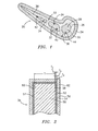
FIG. 1 is a cross-sectional view of a shelled investment casting pattern for forming a gas turbine engine airfoil element. -
FIG. 2 is a sectional view of a refractory metal core of the pattern ofFIG. 1 . -
FIG. 3 is a flowchart of processes for forming and using the pattern ofFIG. 1 . - Like reference numbers and designations in the various drawings indicate like elements.
-
FIG. 1 shows a shelledinvestment casting pattern 20 including apattern 22 and aceramic shell 24. Thepattern 22 includes a sacrificial wax-like material 26 (e.g., natural or synthetic wax or other hydrocarbon-based material) at least partially molded over a core assembly. The core assembly includes aceramic feed core 28 having a series of generallyparallel legs feed core 28 are a series of refractory metal cores (RMCs) 36 and 38. Portions of theRMCs compartments feed core 28 and secured therein viaceramic adhesive 44. Other portions of theRMCs shell 24 so that theRMCs exemplary RMCs 36 provide film cooling passageways for airfoil pressure and suction side surfaces and theexemplary RMC 38 provides airfoil trailing edge cooling. Many other configurations are possible either in the prior art or yet to be developed. -
FIG. 2 shows further details of one of the RMCs (e.g., 38). Theexemplary RMC 38 has asubstrate 50 of refractory metal or a refractory metal-based alloy, intermetallic, or other material. Exemplary refractory metals are Mo, Nb, Ta, and W. These may be obtained as wire or sheet stock and cut and shaped as appropriate. A coating system includes abase layer 52 initially deposited atop the substrate. Although shown discretely for purposes of illustration, in an exemplary embodiment the base layer material becomes diffused into the substrate material. Anintermediate layer 54 is atop the base layer and anouter layer 56 is atop the intermediate layer. - The exemplary outer (and outermost)
layer 56 may provide a combination of chemical protection, mechanical protection, and thermal insulation, (e.g., acting as a substantial barrier to infiltration of casting metal that might alloy with or otherwise attack the substrate and to oxygen to prevent oxidation). Exemplary outer layer materials are ceramics(e.g., aluminum oxide (alumina), mullite, silicon dioxide (silica), and magnesium oxide (magnesia)) built up by deposition (e.g., chemical vapor deposition (CVD)). - The exemplary
intermediate layer 54 may serve principally as a bonding layer for good adherence of theouter layer 56. The intermediate layer may also provide a backup or additional barrier against oxygen. Exemplary intermediate layer materials are carbides or nitrides (e.g., titanium carbide) built up by deposition (e.g., CVD). Such materials are advantageously stable at outer layer deposition temperatures in the range of 1500-1600°C. - The exemplary base (and innermost)
layer 52 may serve to at least temporarily secure the intermediate layer to the substrate while not adversely reacting with the substrate. Exemplary base layer materials comprise metals having a face centered cubic (FCC) structure (e.g., nickel or platinum) built up by electroplating. Such a lattice structure may have advantageous tolerance for incidental infiltration of carbon and/or nitrogen atoms during deposition of the intermediate layer without either catastrophic loss of structural integrity or substantial transmission of such atoms to the substrate. In the absence of such a base layer, in the elevated temperatures typical of CVD there would be substantial infiltration of the carbon and/or nitrogen into the substrate. This infiltration may be particularly problematic with body centered cubic (BCC) lattice structure typical of refractory metals. The infiltration may form an embrittled layer containing the carbide and/or nitride of the refractory metal. This embrittlement may serve as a source of cracks propagating through the coating layers. - The
exemplary substrate 50 is formed, e.g., from sheet stock having a surface including a pair of opposed faces 57 and 58 with a thickness T between. Complex cooling features may be stamped, cut, or otherwise provided in thesubstrate 50. Aninterior surface 60 of the coating system andbase layer 52 sits atop the exterior surface of thesubstrate 50 and anexterior surface 62 of the coating system andouter layer 54 provides an exterior surface of theRMC 38. The transitions between layers may be abrupt or may have compositional gradients. In the exemplary embodiment, thebase layer 52 has an as-deposited thickness T2, theintermediate layer 54 has a thickness T3, and theouter layer 56 has a thickness T4. Exemplary T is at least 50µm, more narrowly at least 100µm. Exemplary T2 is 1-10µm, more narrowly, 1-4µm, or 1-3µm. Exemplary T3 is 0.5-5µm, more narrowly 1-4µm or 1-3µm. Exemplary T4 is at least 4µm, more narrowly 5-25µm, or 15-25µm. -
FIG. 3 shows anexemplary process 200 of manufacture and use (simplified for illustration) of the exemplary. The substrate(s) are formed 202 such as via stamping from sheet stock followed by subsequent bending or other forming to provide a relatively convoluted shape for casting the desired features. After any cleaning to remove residual oxides (e.g., acid and/or alkali wash followed by deionized water rinse), a first metal (e.g., essentially pure nickel) is applied 204 atop the substrate (e.g., by electroplating) to form thebase layer 52. - After any further cleaning, one or more carbides and/or nitrides of one or more second metals (e.g., essentially pure titanium carbide, which is commercially available at low cost) is applied 206 (e.g., by CVD) to form the intermediate layer. At the elevated temperatures of the CVD process, at the inboard Mo/Ni boundary, there may be interdifussion, creating a region of Mo-Ni solid solution. Also, small amounts of carbon may diffuse into the nickel from the deposition vapor, especially at the beginning of the deposition process, before substantial titanium carbide accumulation. The ceramic barrier material (e.g., alumina) is applied 210 (e.g., also by CVD in the same chamber immediately after titanium carbide deposition) to form the
outer layer 56. During the deposition of theouter layer 56, the interdiffusion of the Mo and Ni may continue. Advantageously essentially all the Ni is consumed. The resulting solid solution layer may have a relatively low nickel concentration (e.g., 2% or less at the outboard extreme). The absence of the Ni layer improves thermal performance because of the relatively low melting temperature of the Ni. Such diffusion of the Ni has not been completed at the end of deposition, it may be achieved by a postdeposition heating step. Alternatively or additionally, a predeposition heating step may give the diffusion a partial head start. Additional layers, treatments, and compositional/process variations are possible. - The RMC(s) are then assembled 220 to the feed core(s) or other core(s). Exemplary feed cores may be formed separately (e.g., by molding from silicon-based or other ceramic material) or formed as part of the assembling (e.g., by molding such feed core material partially over the RMC(s)). The assembling may also occur in the assembling of a die for
overmolding 222 the core assembly with the wax-like material 26. Theovermolding 222 forms a pattern which is then shelled 214 (e.g., via a multi-stage stuccoing process forming a silica-based shell). The wax-like material 26 is removed 216 (e.g., via steam autoclave). There may be additional mold preparation (e.g., trimming, firing, assembling). The firing may perform all or part of the postdeposition heating to ensure Mo-Ni interdiffusion noted above. Acasting process 218 introduces one or more molten materials (e.g., for forming a superalloy based on one of more of Ni, Co, and Fe) and allows such materials to solidify. The shell is then removed 220 (e.g., via mechanical means). The core assembly is then removed 222 (e.g., via chemical means). The as-cast casting may then be machined 224 and subject to further treatment 226 (e.g., mechanical treatments, heat treatments, chemical treatments, and coating treatments). - The present system and methods may have one or more advantages over chromium-containing coatings. Notable is reduced toxicity. Chromium containing coatings are typically applied using solutions of hexvalent chromium, a particularly toxic ion. Furthermore, when the coated core is ultimately dissolved, some portion of the chromium will return to this toxic valency. The present coatings may have less than 0.2%, preferably less than 0.01% chromium by weight, and, most preferably, no detectable chromium.
- One or more embodiments of the present invention have been described. Nevertheless, it will be understood that various modifications may be made without departing from the scope of the invention. For example, the coatings may be utilized in the manufacture of cores of existing or yet-developed configuration. The details of any such configuration may influence the details of any particular implementation as may the details of the particular ceramic core and shell materials and casting material and conditions. Accordingly, other embodiments are within the scope of the following claims.
Claims (20)
- An investment casting core (38) comprising:a refractory metal based substrate (50);a first layer (56) consisting principally or a ceramic; anda second layer (54), located between the first layer and the substrate, consisting principally of one or more carbides and/or nitrides,wherein the investment casting core comprises:a third layer (52) located between the second layer and the substrate and consisting in major part of one or more additional metals having an FCC lattice structure; and/orthe substrate comprises: a solid solution surface layer consisting in minor part of said one or more additional metals.
- The core of claim 1 wherein:the ceramic consists essentially of atleast one of alumina, mullite, magnesia, and silica.the substrate (50) is molybdenum based.
- The core of claim 1 or 2 wherein:there is no said third layer (52); andthe one or more additional metals consists essentially of nickel.
- The core of claim 1 wherein:the first layer (56) consists essentially of aluminium oxide and the first thickness is a nominal first thickness.
- The core of any preceding claim wherein at a first location:the first layer (56) has a first thickness is at least 4.0µm;the second layer (54) has a second thickness of 1.0 4.0µm; andthe substrate (50) has a thickness in excess of 50µm.
- The core of any preceding claim being a first core (3 8) in combination with:a ceramic or refractory metal based second core (36); anda hydrocarbon based material (26) in which the first core (38) and the second core (36) are at least partially embedded.
- A method of forming an investment casting core comprising coating a substrate (50) by:applying a first layer (52) atop the substrate, the first layer comprising, in major weight part, a non refractory first metal;applying a second layer (54) atop the first layer, the second layer comprising, in major weight part, a carbide and/or nitride of a second metal; andapplying a third layer (56) atop the second layer, the third layer comprising, in major weight part, a ceramic.
- The method of claim 7 further comprising:essentially diffusing the first metal (52) into the substrate (50), at least a major portion of which occurs during one or both of the applying of the second layer (54) and the applying of the third layer (56).
- The method of claim 7 or 8 wherein:the ceramic consists essentially of an oxide of a third metal.
- The method of claim 7, 8 or 9 wherein:the substrate (50) comprises, in major weight part, one or more refractory metals.
- The method of any of claims 7 to 10 wherein:the first layer (52) is deposited directly atop the substrate (50); the second layer (54) is deposited directly atop the first layer (52); andthe third layer (56) is deposited directly atop the second layer (52).
- The method of any of claims 7 to 11 wherein:the first metal forms an FCC lattice structure.
- The method of claim 7 wherein:the second metal is titanium; andthe ceramic consists essentially of at least one of alumina, mullite, magnesia, and silica.
- The method of any of claims 7 to 13 wherein:the first layer (52) is deposited by electroplating;the second layer (54) is deposited by vapor deposition; andthe third layer (56) is deposited by vapor deposition.
- The method of any of claims 7 to 13 wherein:the first layer (52) is deposited by electroplating;the second layer (54) is deposited by chemical vapor deposition; andthe third layer (56) is deposited by chemical vapor deposition.
- The method of any of claims 7 to 15 wherein:the first layer (52) is deposited to a first thickness of 1-3µm;the second layer (56) is deposited to a second thickness of 1-3µm; andthe third layer (56) is deposited to a third thickness of 15-25µm.
- The method of any of claims 7 to 15 wherein:the first layer (52) is deposited to a first thickness of at least 1µm;the second layer (54) is deposited to a second thickness of at least 0.5µm; andthe third layer (56) is deposited to a third thickness of at least 5µm.
- The method of any of claims 7 to 17 wherein the substrate (50) consists essentially of:a molybdenum based material
- The method of any of claims 7 to 18 further comprising:at least one of assembling the core (38) with a second core (36) and forming a second core partially over the core;molding a sacrificial material (26) to the core (38) and the second core (36); applying a shell (24) to the sacrificial material;essentially removing the sacrificial material;casting a metallic material at least partially in place of the sacrificial material; anddestructively removing the core, the second core, and the shell.
- The method of claim 19 wherein:said destructively removing comprises essentially removing at least the first layer (52) and the second layer (34) using HNO3.
Applications Claiming Priority (1)
| Application Number | Priority Date | Filing Date | Title |
|---|---|---|---|
| US10/973,762 US7207374B2 (en) | 2004-10-26 | 2004-10-26 | Non-oxidizable coating |
Publications (3)
| Publication Number | Publication Date |
|---|---|
| EP1652602A2 EP1652602A2 (en) | 2006-05-03 |
| EP1652602A3 EP1652602A3 (en) | 2006-07-26 |
| EP1652602B1 true EP1652602B1 (en) | 2008-12-17 |
Family
ID=35285463
Family Applications (1)
| Application Number | Title | Priority Date | Filing Date |
|---|---|---|---|
| EP05255510A Expired - Lifetime EP1652602B1 (en) | 2004-10-26 | 2005-09-08 | Non-oxidizable coating |
Country Status (7)
| Country | Link |
|---|---|
| US (2) | US7207374B2 (en) |
| EP (1) | EP1652602B1 (en) |
| JP (1) | JP2006123006A (en) |
| CN (1) | CN1781622A (en) |
| AT (1) | ATE417686T1 (en) |
| DE (1) | DE602005011735D1 (en) |
| MX (1) | MXPA05011518A (en) |
Cited By (1)
| Publication number | Priority date | Publication date | Assignee | Title |
|---|---|---|---|---|
| US9239118B2 (en) | 2013-04-24 | 2016-01-19 | Hamilton Sundstrand Corporation | Valve including multilayer wear plate |
Families Citing this family (22)
| Publication number | Priority date | Publication date | Assignee | Title |
|---|---|---|---|---|
| US7207374B2 (en) * | 2004-10-26 | 2007-04-24 | United Technologies Corporation | Non-oxidizable coating |
| US8197184B2 (en) * | 2006-10-18 | 2012-06-12 | United Technologies Corporation | Vane with enhanced heat transfer |
| US7892652B2 (en) * | 2007-03-13 | 2011-02-22 | United Technologies Corporation | Low stress metallic based coating |
| US8066052B2 (en) * | 2007-06-07 | 2011-11-29 | United Technologies Corporation | Cooled wall thickness control |
| US9174271B2 (en) * | 2008-07-02 | 2015-11-03 | United Technologies Corporation | Casting system for investment casting process |
| JP5289275B2 (en) * | 2008-12-26 | 2013-09-11 | 株式会社東芝 | Steam turbine blade and method for manufacturing steam turbine blade |
| US9486854B2 (en) * | 2012-09-10 | 2016-11-08 | United Technologies Corporation | Ceramic and refractory metal core assembly |
| WO2014063336A1 (en) * | 2012-10-26 | 2014-05-01 | 西安西工大超晶科技发展有限责任公司 | Aluminum alloy investment casting small-sized inner cavity molding method |
| US20140182809A1 (en) * | 2012-12-28 | 2014-07-03 | United Technologies Corporation | Mullite-containing investment casting core |
| US9975173B2 (en) | 2013-06-03 | 2018-05-22 | United Technologies Corporation | Castings and manufacture methods |
| CA2885074A1 (en) * | 2014-04-24 | 2015-10-24 | Howmet Corporation | Ceramic casting core made by additive manufacturing |
| US10041890B2 (en) | 2015-08-04 | 2018-08-07 | United Technologies Corporation | Radiopaque protective fill for manufacture, repair, or remanufacture of cooled components |
| US10118217B2 (en) * | 2015-12-17 | 2018-11-06 | General Electric Company | Method and assembly for forming components having internal passages using a jacketed core |
| US10137499B2 (en) * | 2015-12-17 | 2018-11-27 | General Electric Company | Method and assembly for forming components having an internal passage defined therein |
| US20170333978A1 (en) * | 2016-05-19 | 2017-11-23 | United Technologies Corporation | Casting system for investment casting process |
| US10556269B1 (en) * | 2017-03-29 | 2020-02-11 | United Technologies Corporation | Apparatus for and method of making multi-walled passages in components |
| US10596621B1 (en) | 2017-03-29 | 2020-03-24 | United Technologies Corporation | Method of making complex internal passages in turbine airfoils |
| CN107297483B (en) * | 2017-04-26 | 2019-05-14 | 霍山县龙鑫金属制品有限公司 | Aluminum alloy thin-wall part casting method |
| US11033955B2 (en) | 2017-10-03 | 2021-06-15 | Raytheon Technologies Corporation | Printing-enhanced casting cores |
| FR3097791B1 (en) | 2019-06-28 | 2021-06-18 | Safran Aircraft Engines | HOT CONFORMATION CORE OF A METAL PIECE AND MANUFACTURING, REGENERATION AND CONFORMATION PROCESS |
| CN116944417B (en) * | 2023-08-11 | 2025-08-29 | 襄阳聚力新材料科技有限公司 | A metal mold thermal insulation coating for low-pressure casting of aluminum alloy |
| FR3167322A1 (en) * | 2024-10-11 | 2026-04-17 | Safran | Method for manufacturing a refractory metal core |
Family Cites Families (28)
| Publication number | Priority date | Publication date | Assignee | Title |
|---|---|---|---|---|
| US2682101A (en) * | 1946-06-01 | 1954-06-29 | Whitfield & Sheshunoff Inc | Oxidation protected tungsten and molybdenum bodies and method of producing same |
| US3634208A (en) | 1968-09-26 | 1972-01-11 | Aiden Kk | Coloring method of aluminum anodic oxide coating film |
| US3957104A (en) * | 1974-02-27 | 1976-05-18 | The United States Of America As Represented By The Administrator Of The United States National Aeronautics And Space Administration | Method of making an apertured casting |
| CH640441A5 (en) * | 1979-09-10 | 1984-01-13 | Hans Schneider | METHOD FOR PRODUCING CASTING PIECES BY PRECISION CASTING. |
| IL58548A (en) | 1979-10-24 | 1983-07-31 | Iscar Ltd | Sintered hard metal products having a multi-layer wearresistant coating |
| US4357382A (en) | 1980-11-06 | 1982-11-02 | Fansteel Inc. | Coated cemented carbide bodies |
| US5035957A (en) * | 1981-11-27 | 1991-07-30 | Sri International | Coated metal product and precursor for forming same |
| US4857116A (en) * | 1981-11-27 | 1989-08-15 | S R I International | Process for applying coatings of zirconium and/or titanium and a less noble metal to metal substrates and for converting the zirconium and/or titanium to a nitride, carbide, boride, or silicide |
| US4537382A (en) | 1982-02-04 | 1985-08-27 | Sperry Corporation | Sway rod suspension system |
| US4911795A (en) | 1987-08-14 | 1990-03-27 | Morton Thiokol, Inc. | Method of preserving a composite material cased solid propellant rocket motor |
| US5135801A (en) * | 1988-06-13 | 1992-08-04 | Sandvik Ab | Diffusion barrier coating material |
| US5250367A (en) | 1990-09-17 | 1993-10-05 | Kennametal Inc. | Binder enriched CVD and PVD coated cutting tool |
| US5104514A (en) | 1991-05-16 | 1992-04-14 | The United States Of America As Represented By The Secretary Of The Navy | Protective coating system for aluminum |
| IL109857A (en) | 1994-06-01 | 1998-06-15 | Almag Al | Electrolytic process and apparatus for coating metals |
| US5652045A (en) | 1994-10-20 | 1997-07-29 | Mitsubishi Materials Corporation | Coated tungsten carbide-based cemented carbide blade member |
| US5928771A (en) | 1995-05-12 | 1999-07-27 | Diamond Black Technologies, Inc. | Disordered coating with cubic boron nitride dispersed therein |
| US5948541A (en) | 1996-04-04 | 1999-09-07 | Kennametal Inc. | Boron and nitrogen containing coating and method for making |
| JP2000511974A (en) * | 1996-06-13 | 2000-09-12 | シーメンス アクチエンゲゼルシヤフト | Articles with a protective coating system with an improved anchoring layer and method of making the same |
| AT1669U1 (en) * | 1996-11-22 | 1997-09-25 | Plansee Ag | OXIDATION PROTECTIVE LAYER FOR REFRACTIVE METALS |
| EP0846785A3 (en) | 1996-12-03 | 2000-09-20 | Harris Corporation | A method of metalizing ceramic members |
| US6365028B1 (en) | 1997-12-17 | 2002-04-02 | Isle Coat Limited | Method for producing hard protection coatings on articles made of aluminum alloys |
| JP3255147B2 (en) * | 1998-06-19 | 2002-02-12 | 株式会社デンソー | Surge protection circuit for insulated gate transistor |
| US6197178B1 (en) | 1999-04-02 | 2001-03-06 | Microplasmic Corporation | Method for forming ceramic coatings by micro-arc oxidation of reactive metals |
| US6849328B1 (en) | 1999-07-02 | 2005-02-01 | Ppg Industries Ohio, Inc. | Light-transmitting and/or coated article with removable protective coating and methods of making the same |
| US20010046605A1 (en) | 2000-02-16 | 2001-11-29 | Jean-Paul Huni | Refractory coating for components of an aluminium electrolysis cell |
| US6637500B2 (en) | 2001-10-24 | 2003-10-28 | United Technologies Corporation | Cores for use in precision investment casting |
| US6668906B2 (en) * | 2002-04-29 | 2003-12-30 | United Technologies Corporation | Shaped core for cast cooling passages and enhanced part definition |
| US7207374B2 (en) * | 2004-10-26 | 2007-04-24 | United Technologies Corporation | Non-oxidizable coating |
-
2004
- 2004-10-26 US US10/973,762 patent/US7207374B2/en not_active Expired - Lifetime
-
2005
- 2005-09-08 DE DE602005011735T patent/DE602005011735D1/en not_active Expired - Lifetime
- 2005-09-08 AT AT05255510T patent/ATE417686T1/en not_active IP Right Cessation
- 2005-09-08 EP EP05255510A patent/EP1652602B1/en not_active Expired - Lifetime
- 2005-10-26 CN CNA2005101180445A patent/CN1781622A/en active Pending
- 2005-10-26 JP JP2005311239A patent/JP2006123006A/en active Pending
- 2005-10-26 MX MXPA05011518A patent/MXPA05011518A/en not_active Application Discontinuation
-
2006
- 2006-09-26 US US11/527,200 patent/US7581581B2/en not_active Expired - Lifetime
Cited By (2)
| Publication number | Priority date | Publication date | Assignee | Title |
|---|---|---|---|---|
| US9239118B2 (en) | 2013-04-24 | 2016-01-19 | Hamilton Sundstrand Corporation | Valve including multilayer wear plate |
| US9470328B2 (en) | 2013-04-24 | 2016-10-18 | Hamilton Sundstrand Corporation | Valve including multilayer wear plate |
Also Published As
| Publication number | Publication date |
|---|---|
| MXPA05011518A (en) | 2006-05-02 |
| US7581581B2 (en) | 2009-09-01 |
| US7207374B2 (en) | 2007-04-24 |
| JP2006123006A (en) | 2006-05-18 |
| US20070017653A1 (en) | 2007-01-25 |
| CN1781622A (en) | 2006-06-07 |
| ATE417686T1 (en) | 2009-01-15 |
| EP1652602A2 (en) | 2006-05-03 |
| US20060086478A1 (en) | 2006-04-27 |
| EP1652602A3 (en) | 2006-07-26 |
| DE602005011735D1 (en) | 2009-01-29 |
Similar Documents
| Publication | Publication Date | Title |
|---|---|---|
| US7207374B2 (en) | Non-oxidizable coating | |
| EP1652601B1 (en) | Non-Oxidizable coating | |
| US12042854B2 (en) | Castings and manufacture methods | |
| EP1914030B1 (en) | Investment casting cores and their use in investment casting | |
| US8100165B2 (en) | Investment casting cores and methods | |
| EP2511024B1 (en) | Contoured metallic casting core | |
| EP1764170B1 (en) | Method for core removal in lost wax casting | |
| EP1769861B1 (en) | Manufacture of casting cores | |
| JP2007253237A (en) | Attaching method and investment casting method | |
| JP2007307618A (en) | Method for manufacturing combination investment casting core, and investment casting core | |
| WO2014035522A2 (en) | Blade outer air seal hybrid casting core | |
| CN114051434A (en) | Method for producing a metal part |
Legal Events
| Date | Code | Title | Description |
|---|---|---|---|
| PUAI | Public reference made under article 153(3) epc to a published international application that has entered the european phase |
Free format text: ORIGINAL CODE: 0009012 |
|
| AK | Designated contracting states |
Kind code of ref document: A2 Designated state(s): AT BE BG CH CY CZ DE DK EE ES FI FR GB GR HU IE IS IT LI LT LU LV MC NL PL PT RO SE SI SK TR |
|
| AX | Request for extension of the european patent |
Extension state: AL BA HR MK YU |
|
| PUAL | Search report despatched |
Free format text: ORIGINAL CODE: 0009013 |
|
| AK | Designated contracting states |
Kind code of ref document: A3 Designated state(s): AT BE BG CH CY CZ DE DK EE ES FI FR GB GR HU IE IS IT LI LT LU LV MC NL PL PT RO SE SI SK TR |
|
| AX | Request for extension of the european patent |
Extension state: AL BA HR MK YU |
|
| 17P | Request for examination filed |
Effective date: 20070126 |
|
| 17Q | First examination report despatched |
Effective date: 20070301 |
|
| AKX | Designation fees paid |
Designated state(s): AT BE BG CH CY CZ DE DK EE ES FI FR GB GR HU IE IS IT LI LT LU LV MC NL PL PT RO SE SI SK TR |
|
| GRAP | Despatch of communication of intention to grant a patent |
Free format text: ORIGINAL CODE: EPIDOSNIGR1 |
|
| GRAS | Grant fee paid |
Free format text: ORIGINAL CODE: EPIDOSNIGR3 |
|
| GRAS | Grant fee paid |
Free format text: ORIGINAL CODE: EPIDOSNIGR3 |
|
| GRAA | (expected) grant |
Free format text: ORIGINAL CODE: 0009210 |
|
| AK | Designated contracting states |
Kind code of ref document: B1 Designated state(s): AT BE BG CH CY CZ DE DK EE ES FI FR GB GR HU IE IS IT LI LT LU LV MC NL PL PT RO SE SI SK TR |
|
| REG | Reference to a national code |
Ref country code: GB Ref legal event code: FG4D |
|
| REG | Reference to a national code |
Ref country code: CH Ref legal event code: EP |
|
| REG | Reference to a national code |
Ref country code: IE Ref legal event code: FG4D |
|
| REF | Corresponds to: |
Ref document number: 602005011735 Country of ref document: DE Date of ref document: 20090129 Kind code of ref document: P |
|
| PG25 | Lapsed in a contracting state [announced via postgrant information from national office to epo] |
Ref country code: LT Free format text: LAPSE BECAUSE OF FAILURE TO SUBMIT A TRANSLATION OF THE DESCRIPTION OR TO PAY THE FEE WITHIN THE PRESCRIBED TIME-LIMIT Effective date: 20081217 |
|
| PG25 | Lapsed in a contracting state [announced via postgrant information from national office to epo] |
Ref country code: SI Free format text: LAPSE BECAUSE OF FAILURE TO SUBMIT A TRANSLATION OF THE DESCRIPTION OR TO PAY THE FEE WITHIN THE PRESCRIBED TIME-LIMIT Effective date: 20081217 Ref country code: FI Free format text: LAPSE BECAUSE OF FAILURE TO SUBMIT A TRANSLATION OF THE DESCRIPTION OR TO PAY THE FEE WITHIN THE PRESCRIBED TIME-LIMIT Effective date: 20081217 Ref country code: LV Free format text: LAPSE BECAUSE OF FAILURE TO SUBMIT A TRANSLATION OF THE DESCRIPTION OR TO PAY THE FEE WITHIN THE PRESCRIBED TIME-LIMIT Effective date: 20081217 Ref country code: NL Free format text: LAPSE BECAUSE OF FAILURE TO SUBMIT A TRANSLATION OF THE DESCRIPTION OR TO PAY THE FEE WITHIN THE PRESCRIBED TIME-LIMIT Effective date: 20081217 Ref country code: PL Free format text: LAPSE BECAUSE OF FAILURE TO SUBMIT A TRANSLATION OF THE DESCRIPTION OR TO PAY THE FEE WITHIN THE PRESCRIBED TIME-LIMIT Effective date: 20081217 |
|
| NLV1 | Nl: lapsed or annulled due to failure to fulfill the requirements of art. 29p and 29m of the patents act | ||
| PG25 | Lapsed in a contracting state [announced via postgrant information from national office to epo] |
Ref country code: BE Free format text: LAPSE BECAUSE OF FAILURE TO SUBMIT A TRANSLATION OF THE DESCRIPTION OR TO PAY THE FEE WITHIN THE PRESCRIBED TIME-LIMIT Effective date: 20081217 Ref country code: BG Free format text: LAPSE BECAUSE OF FAILURE TO SUBMIT A TRANSLATION OF THE DESCRIPTION OR TO PAY THE FEE WITHIN THE PRESCRIBED TIME-LIMIT Effective date: 20090317 Ref country code: RO Free format text: LAPSE BECAUSE OF FAILURE TO SUBMIT A TRANSLATION OF THE DESCRIPTION OR TO PAY THE FEE WITHIN THE PRESCRIBED TIME-LIMIT Effective date: 20081217 Ref country code: ES Free format text: LAPSE BECAUSE OF FAILURE TO SUBMIT A TRANSLATION OF THE DESCRIPTION OR TO PAY THE FEE WITHIN THE PRESCRIBED TIME-LIMIT Effective date: 20090328 Ref country code: EE Free format text: LAPSE BECAUSE OF FAILURE TO SUBMIT A TRANSLATION OF THE DESCRIPTION OR TO PAY THE FEE WITHIN THE PRESCRIBED TIME-LIMIT Effective date: 20081217 |
|
| PG25 | Lapsed in a contracting state [announced via postgrant information from national office to epo] |
Ref country code: SE Free format text: LAPSE BECAUSE OF FAILURE TO SUBMIT A TRANSLATION OF THE DESCRIPTION OR TO PAY THE FEE WITHIN THE PRESCRIBED TIME-LIMIT Effective date: 20090317 Ref country code: CZ Free format text: LAPSE BECAUSE OF FAILURE TO SUBMIT A TRANSLATION OF THE DESCRIPTION OR TO PAY THE FEE WITHIN THE PRESCRIBED TIME-LIMIT Effective date: 20081217 Ref country code: AT Free format text: LAPSE BECAUSE OF FAILURE TO SUBMIT A TRANSLATION OF THE DESCRIPTION OR TO PAY THE FEE WITHIN THE PRESCRIBED TIME-LIMIT Effective date: 20081217 Ref country code: PT Free format text: LAPSE BECAUSE OF FAILURE TO SUBMIT A TRANSLATION OF THE DESCRIPTION OR TO PAY THE FEE WITHIN THE PRESCRIBED TIME-LIMIT Effective date: 20090518 Ref country code: IS Free format text: LAPSE BECAUSE OF FAILURE TO SUBMIT A TRANSLATION OF THE DESCRIPTION OR TO PAY THE FEE WITHIN THE PRESCRIBED TIME-LIMIT Effective date: 20090417 |
|
| PG25 | Lapsed in a contracting state [announced via postgrant information from national office to epo] |
Ref country code: SK Free format text: LAPSE BECAUSE OF FAILURE TO SUBMIT A TRANSLATION OF THE DESCRIPTION OR TO PAY THE FEE WITHIN THE PRESCRIBED TIME-LIMIT Effective date: 20081217 |
|
| PLBE | No opposition filed within time limit |
Free format text: ORIGINAL CODE: 0009261 |
|
| STAA | Information on the status of an ep patent application or granted ep patent |
Free format text: STATUS: NO OPPOSITION FILED WITHIN TIME LIMIT |
|
| PG25 | Lapsed in a contracting state [announced via postgrant information from national office to epo] |
Ref country code: DK Free format text: LAPSE BECAUSE OF FAILURE TO SUBMIT A TRANSLATION OF THE DESCRIPTION OR TO PAY THE FEE WITHIN THE PRESCRIBED TIME-LIMIT Effective date: 20081217 |
|
| 26N | No opposition filed |
Effective date: 20090918 |
|
| PG25 | Lapsed in a contracting state [announced via postgrant information from national office to epo] |
Ref country code: MC Free format text: LAPSE BECAUSE OF NON-PAYMENT OF DUE FEES Effective date: 20090930 |
|
| REG | Reference to a national code |
Ref country code: CH Ref legal event code: PL |
|
| REG | Reference to a national code |
Ref country code: IE Ref legal event code: MM4A |
|
| REG | Reference to a national code |
Ref country code: FR Ref legal event code: ST Effective date: 20100531 |
|
| PG25 | Lapsed in a contracting state [announced via postgrant information from national office to epo] |
Ref country code: FR Free format text: LAPSE BECAUSE OF NON-PAYMENT OF DUE FEES Effective date: 20090930 Ref country code: IE Free format text: LAPSE BECAUSE OF NON-PAYMENT OF DUE FEES Effective date: 20090908 |
|
| PG25 | Lapsed in a contracting state [announced via postgrant information from national office to epo] |
Ref country code: LI Free format text: LAPSE BECAUSE OF NON-PAYMENT OF DUE FEES Effective date: 20090930 Ref country code: CH Free format text: LAPSE BECAUSE OF NON-PAYMENT OF DUE FEES Effective date: 20090930 Ref country code: GR Free format text: LAPSE BECAUSE OF FAILURE TO SUBMIT A TRANSLATION OF THE DESCRIPTION OR TO PAY THE FEE WITHIN THE PRESCRIBED TIME-LIMIT Effective date: 20090318 |
|
| PG25 | Lapsed in a contracting state [announced via postgrant information from national office to epo] |
Ref country code: IT Free format text: LAPSE BECAUSE OF FAILURE TO SUBMIT A TRANSLATION OF THE DESCRIPTION OR TO PAY THE FEE WITHIN THE PRESCRIBED TIME-LIMIT Effective date: 20081217 |
|
| PG25 | Lapsed in a contracting state [announced via postgrant information from national office to epo] |
Ref country code: LU Free format text: LAPSE BECAUSE OF NON-PAYMENT OF DUE FEES Effective date: 20090908 |
|
| PG25 | Lapsed in a contracting state [announced via postgrant information from national office to epo] |
Ref country code: HU Free format text: LAPSE BECAUSE OF FAILURE TO SUBMIT A TRANSLATION OF THE DESCRIPTION OR TO PAY THE FEE WITHIN THE PRESCRIBED TIME-LIMIT Effective date: 20090618 |
|
| PG25 | Lapsed in a contracting state [announced via postgrant information from national office to epo] |
Ref country code: TR Free format text: LAPSE BECAUSE OF FAILURE TO SUBMIT A TRANSLATION OF THE DESCRIPTION OR TO PAY THE FEE WITHIN THE PRESCRIBED TIME-LIMIT Effective date: 20081217 |
|
| PG25 | Lapsed in a contracting state [announced via postgrant information from national office to epo] |
Ref country code: CY Free format text: LAPSE BECAUSE OF FAILURE TO SUBMIT A TRANSLATION OF THE DESCRIPTION OR TO PAY THE FEE WITHIN THE PRESCRIBED TIME-LIMIT Effective date: 20081217 |
|
| PGFP | Annual fee paid to national office [announced via postgrant information from national office to epo] |
Ref country code: DE Payment date: 20120905 Year of fee payment: 8 |
|
| REG | Reference to a national code |
Ref country code: DE Ref legal event code: R119 Ref document number: 602005011735 Country of ref document: DE Effective date: 20140401 |
|
| PG25 | Lapsed in a contracting state [announced via postgrant information from national office to epo] |
Ref country code: DE Free format text: LAPSE BECAUSE OF NON-PAYMENT OF DUE FEES Effective date: 20140401 |
|
| PGFP | Annual fee paid to national office [announced via postgrant information from national office to epo] |
Ref country code: GB Payment date: 20230823 Year of fee payment: 19 |
|
| GBPC | Gb: european patent ceased through non-payment of renewal fee |
Effective date: 20240908 |
|
| PG25 | Lapsed in a contracting state [announced via postgrant information from national office to epo] |
Ref country code: GB Free format text: LAPSE BECAUSE OF NON-PAYMENT OF DUE FEES Effective date: 20240908 |