EP1652543A1 - A holding needle comprising gripping flanges - Google Patents
A holding needle comprising gripping flanges Download PDFInfo
- Publication number
- EP1652543A1 EP1652543A1 EP05292112A EP05292112A EP1652543A1 EP 1652543 A1 EP1652543 A1 EP 1652543A1 EP 05292112 A EP05292112 A EP 05292112A EP 05292112 A EP05292112 A EP 05292112A EP 1652543 A1 EP1652543 A1 EP 1652543A1
- Authority
- EP
- European Patent Office
- Prior art keywords
- holding body
- flanges
- take
- needle
- spigot
- Prior art date
- Legal status (The legal status is an assumption and is not a legal conclusion. Google has not performed a legal analysis and makes no representation as to the accuracy of the status listed.)
- Granted
Links
Images



Classifications
-
- B—PERFORMING OPERATIONS; TRANSPORTING
- B23—MACHINE TOOLS; METAL-WORKING NOT OTHERWISE PROVIDED FOR
- B23P—METAL-WORKING NOT OTHERWISE PROVIDED FOR; COMBINED OPERATIONS; UNIVERSAL MACHINE TOOLS
- B23P19/00—Machines for simply fitting together or separating metal parts or objects, or metal and non-metal parts, whether or not involving some deformation; Tools or devices therefor so far as not provided for in other classes
- B23P19/04—Machines for simply fitting together or separating metal parts or objects, or metal and non-metal parts, whether or not involving some deformation; Tools or devices therefor so far as not provided for in other classes for assembling or disassembling parts
-
- A—HUMAN NECESSITIES
- A61—MEDICAL OR VETERINARY SCIENCE; HYGIENE
- A61M—DEVICES FOR INTRODUCING MEDIA INTO, OR ONTO, THE BODY; DEVICES FOR TRANSDUCING BODY MEDIA OR FOR TAKING MEDIA FROM THE BODY; DEVICES FOR PRODUCING OR ENDING SLEEP OR STUPOR
- A61M5/00—Devices for bringing media into the body in a subcutaneous, intra-vascular or intramuscular way; Accessories therefor, e.g. filling or cleaning devices, arm-rests
- A61M5/14—Infusion devices, e.g. infusing by gravity; Blood infusion; Accessories therefor
- A61M5/162—Needle sets, i.e. connections by puncture between reservoir and tube ; Connections between reservoir and tube
-
- A—HUMAN NECESSITIES
- A61—MEDICAL OR VETERINARY SCIENCE; HYGIENE
- A61B—DIAGNOSIS; SURGERY; IDENTIFICATION
- A61B17/00—Surgical instruments, devices or methods
- A61B17/34—Trocars; Puncturing needles
- A61B17/3417—Details of tips or shafts, e.g. grooves, expandable, bendable; Multiple coaxial sliding cannulas, e.g. for dilating
- A61B17/3421—Cannulas
-
- A—HUMAN NECESSITIES
- A61—MEDICAL OR VETERINARY SCIENCE; HYGIENE
- A61B—DIAGNOSIS; SURGERY; IDENTIFICATION
- A61B17/00—Surgical instruments, devices or methods
- A61B17/34—Trocars; Puncturing needles
- A61B17/3417—Details of tips or shafts, e.g. grooves, expandable, bendable; Multiple coaxial sliding cannulas, e.g. for dilating
-
- A—HUMAN NECESSITIES
- A61—MEDICAL OR VETERINARY SCIENCE; HYGIENE
- A61M—DEVICES FOR INTRODUCING MEDIA INTO, OR ONTO, THE BODY; DEVICES FOR TRANSDUCING BODY MEDIA OR FOR TAKING MEDIA FROM THE BODY; DEVICES FOR PRODUCING OR ENDING SLEEP OR STUPOR
- A61M5/00—Devices for bringing media into the body in a subcutaneous, intra-vascular or intramuscular way; Accessories therefor, e.g. filling or cleaning devices, arm-rests
- A61M5/14—Infusion devices, e.g. infusing by gravity; Blood infusion; Accessories therefor
- A61M5/162—Needle sets, i.e. connections by puncture between reservoir and tube ; Connections between reservoir and tube
- A61M2005/1623—Details of air intake
-
- A—HUMAN NECESSITIES
- A61—MEDICAL OR VETERINARY SCIENCE; HYGIENE
- A61M—DEVICES FOR INTRODUCING MEDIA INTO, OR ONTO, THE BODY; DEVICES FOR TRANSDUCING BODY MEDIA OR FOR TAKING MEDIA FROM THE BODY; DEVICES FOR PRODUCING OR ENDING SLEEP OR STUPOR
- A61M25/00—Catheters; Hollow probes
- A61M25/01—Introducing, guiding, advancing, emplacing or holding catheters
- A61M25/06—Body-piercing guide needles or the like
-
- A—HUMAN NECESSITIES
- A61—MEDICAL OR VETERINARY SCIENCE; HYGIENE
- A61M—DEVICES FOR INTRODUCING MEDIA INTO, OR ONTO, THE BODY; DEVICES FOR TRANSDUCING BODY MEDIA OR FOR TAKING MEDIA FROM THE BODY; DEVICES FOR PRODUCING OR ENDING SLEEP OR STUPOR
- A61M25/00—Catheters; Hollow probes
- A61M25/01—Introducing, guiding, advancing, emplacing or holding catheters
- A61M25/06—Body-piercing guide needles or the like
- A61M25/065—Guide needles
-
- A—HUMAN NECESSITIES
- A61—MEDICAL OR VETERINARY SCIENCE; HYGIENE
- A61M—DEVICES FOR INTRODUCING MEDIA INTO, OR ONTO, THE BODY; DEVICES FOR TRANSDUCING BODY MEDIA OR FOR TAKING MEDIA FROM THE BODY; DEVICES FOR PRODUCING OR ENDING SLEEP OR STUPOR
- A61M5/00—Devices for bringing media into the body in a subcutaneous, intra-vascular or intramuscular way; Accessories therefor, e.g. filling or cleaning devices, arm-rests
- A61M5/14—Infusion devices, e.g. infusing by gravity; Blood infusion; Accessories therefor
- A61M5/158—Needles for infusions; Accessories therefor, e.g. for inserting infusion needles, or for holding them on the body
-
- Y—GENERAL TAGGING OF NEW TECHNOLOGICAL DEVELOPMENTS; GENERAL TAGGING OF CROSS-SECTIONAL TECHNOLOGIES SPANNING OVER SEVERAL SECTIONS OF THE IPC; TECHNICAL SUBJECTS COVERED BY FORMER USPC CROSS-REFERENCE ART COLLECTIONS [XRACs] AND DIGESTS
- Y10—TECHNICAL SUBJECTS COVERED BY FORMER USPC
- Y10T—TECHNICAL SUBJECTS COVERED BY FORMER US CLASSIFICATION
- Y10T29/00—Metal working
- Y10T29/49—Method of mechanical manufacture
- Y10T29/49826—Assembling or joining
-
- Y—GENERAL TAGGING OF NEW TECHNOLOGICAL DEVELOPMENTS; GENERAL TAGGING OF CROSS-SECTIONAL TECHNOLOGIES SPANNING OVER SEVERAL SECTIONS OF THE IPC; TECHNICAL SUBJECTS COVERED BY FORMER USPC CROSS-REFERENCE ART COLLECTIONS [XRACs] AND DIGESTS
- Y10—TECHNICAL SUBJECTS COVERED BY FORMER USPC
- Y10T—TECHNICAL SUBJECTS COVERED BY FORMER US CLASSIFICATION
- Y10T29/00—Metal working
- Y10T29/49—Method of mechanical manufacture
- Y10T29/49826—Assembling or joining
- Y10T29/49892—Joining plate edge perpendicularly to frame
-
- Y—GENERAL TAGGING OF NEW TECHNOLOGICAL DEVELOPMENTS; GENERAL TAGGING OF CROSS-SECTIONAL TECHNOLOGIES SPANNING OVER SEVERAL SECTIONS OF THE IPC; TECHNICAL SUBJECTS COVERED BY FORMER USPC CROSS-REFERENCE ART COLLECTIONS [XRACs] AND DIGESTS
- Y10—TECHNICAL SUBJECTS COVERED BY FORMER USPC
- Y10T—TECHNICAL SUBJECTS COVERED BY FORMER US CLASSIFICATION
- Y10T29/00—Metal working
- Y10T29/49—Method of mechanical manufacture
- Y10T29/49826—Assembling or joining
- Y10T29/49895—Associating parts by use of aligning means [e.g., use of a drift pin or a "fixture"]
-
- Y—GENERAL TAGGING OF NEW TECHNOLOGICAL DEVELOPMENTS; GENERAL TAGGING OF CROSS-SECTIONAL TECHNOLOGIES SPANNING OVER SEVERAL SECTIONS OF THE IPC; TECHNICAL SUBJECTS COVERED BY FORMER USPC CROSS-REFERENCE ART COLLECTIONS [XRACs] AND DIGESTS
- Y10—TECHNICAL SUBJECTS COVERED BY FORMER USPC
- Y10T—TECHNICAL SUBJECTS COVERED BY FORMER US CLASSIFICATION
- Y10T29/00—Metal working
- Y10T29/49—Method of mechanical manufacture
- Y10T29/49826—Assembling or joining
- Y10T29/49895—Associating parts by use of aligning means [e.g., use of a drift pin or a "fixture"]
- Y10T29/49897—Registering mating opposed tool parts [e.g., registering a punch and a cooperating die]
-
- Y—GENERAL TAGGING OF NEW TECHNOLOGICAL DEVELOPMENTS; GENERAL TAGGING OF CROSS-SECTIONAL TECHNOLOGIES SPANNING OVER SEVERAL SECTIONS OF THE IPC; TECHNICAL SUBJECTS COVERED BY FORMER USPC CROSS-REFERENCE ART COLLECTIONS [XRACs] AND DIGESTS
- Y10—TECHNICAL SUBJECTS COVERED BY FORMER USPC
- Y10T—TECHNICAL SUBJECTS COVERED BY FORMER US CLASSIFICATION
- Y10T29/00—Metal working
- Y10T29/49—Method of mechanical manufacture
- Y10T29/49826—Assembling or joining
- Y10T29/49895—Associating parts by use of aligning means [e.g., use of a drift pin or a "fixture"]
- Y10T29/49899—Associating parts by use of aligning means [e.g., use of a drift pin or a "fixture"] by multiple cooperating aligning means
-
- Y—GENERAL TAGGING OF NEW TECHNOLOGICAL DEVELOPMENTS; GENERAL TAGGING OF CROSS-SECTIONAL TECHNOLOGIES SPANNING OVER SEVERAL SECTIONS OF THE IPC; TECHNICAL SUBJECTS COVERED BY FORMER USPC CROSS-REFERENCE ART COLLECTIONS [XRACs] AND DIGESTS
- Y10—TECHNICAL SUBJECTS COVERED BY FORMER USPC
- Y10T—TECHNICAL SUBJECTS COVERED BY FORMER US CLASSIFICATION
- Y10T29/00—Metal working
- Y10T29/49—Method of mechanical manufacture
- Y10T29/49826—Assembling or joining
- Y10T29/49947—Assembling or joining by applying separate fastener
Definitions
- the invention concerns the general field of take-off needles adapted to be pricked through an elastic wall in order to take off liquid contained in a container closed by the wall.
- the invention more particularly concerns such a take-off needle which comprises a hollow lance generally formed from a fine steel tube provided at its distal end with a sharp pricking tip and connected to a pipe by its proximal end.
- the pricking tip is thus adapted to pass through said elastic wall to enable the liquid to flow in the hollow lance towards the pipe which comprises a spigot to which for example may be connected a tube by which the taken-off liquid will be collected, for example in a container.
- Such needles generally comprise a polymer holding body molded over the proximal end of the hollow lance, the holding body forming an internal channel ensuring the flow of the liquid from the hollow lance to the spigot of the pipe.
- the holding body also enables the needle to be manipulated, in particular during the pricking operation.
- Such needles are for example used to take off liquid from a bottle closed by a rubber bung.
- the spigot of the pipe is then connected in advance to a tube leading to a container.
- the needle is pricked into the bung such that the distal end passes through the bung and reaches the medium to be taken-off, the user holding the needle by the holding body.
- the liquid to be taken off then flows to the container, for example by gravity or with the help of a peristaltic pump or else by the pressurization of the bottle containing the liquid.
- Such needles may for example be what is referred to as “single” needles, that is to say that they only comprise a single hollow lance connected to just one pipe; or else they may be what is referred to as “double” needles, that is to say that they comprise a hollow lance of which the flow is divided into two at the holding body to go to two pipes for taking off the liquid simultaneously to two different containers.
- These needles may be vented, that is to say that they comprise a second hollow lance, of smaller diameter than the main hollow lance, which is inserted in the main hollow lance.
- This second hollow lance allows the progressive introduction of air into the bottle containing the liquid to take off as the liquid flows in the main hollow lance.
- Such a vented needle makes it possible to carry out take-off operations from a fluid-tight bottle.
- take-off needles are known which are provided to be manipulated directly by the holding body.
- the form of the holding body is defined by its function, i.e. the connection of the hollow lance to the pipe, it may be grasped in the hand by the user to manipulate the take-off needle, in particular to perform the pricking operation, without touching the hollow lance.
- the holding body comprises a cylindrical body extending from the hollow lance and in line therewith.
- the spigot of the pipe is connected to the cylindrical body so as to project transversely or obliquely. Several spigots may project from the cylindrical body.
- take-off needles which are adapted to be manipulated by their holding body, as set out above, and which further comprise a guard formed by a plate that is transverse to the cylindrical body of the holding body.
- the guard is disposed on the holding body in the vicinity of the junction between the cylindrical body and the hollow lance. During the pricking operation, the guard enables the fingers of the user to be held clear of the hollow lance by a physical barrier.
- the guard forms a grip for the user's fingers which thereby avoid the risk of slipping onto the hollow lance.
- the object of the invention is to improve this type of take-off needle by providing a needle which is more ergonomic.
- the invention is directed to a take-off needle comprising a hollow lance having a distal end adapted to perform a pricking operation, said hollow lance being connected to at least one pipe provided with a spigot for it to be connected to a tube, and comprising a body for holding the hollow lance and pipe relative to each other such that the spigot projects from the holding body, said needle being characterized in that it further comprises two flanges held on respective sides of and spaced from the holding body by virtue of a spacer disposed between each flange and the holding body, said flanges extending in a Innniturlinal direction from the spigot to the vicinity of the proximal end of the hollow lance, the width of each flange being greater than the width of the portion of the holding body facing the flanges.
- the holding body is, as it were, sandwiched between the two flanges.
- these flanges transversely cover at least a portion of the holding body, it is much simpler for the user's hand to grasp the needle by both flanges than by the holding body.
- each of the flanges also extends between the spigot and the proximal end of the holding body, to be better held by the hand.
- Each of the flanges may furthermore be arcuate so as to bowed towards the holding body.
- the arcuate form of the flanges provides longitudinal centering of the user's hand with respect to the holding body.
- the hand intuitively locates around the arcuate flanges and in the concave form which they define.
- each of the flanges may also have a transverse curvature so as to present a rounded surface.
- the needle according to the invention may further comprise the following advantageous features, either alone or in combination:
- the invention also relates to a method of manufacturing a take-off needle as presented above, said method comprising the following steps:
- Figures 1 and 2 each represent a take-off needle in accordance with one embodiment of the invention.
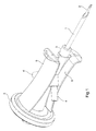
- Figure 1 represents a double take-off needle comprising a main hollow lance 1 adapted for the passage of the liquid to take off, a venting hollow lance 2 adapted to inject air into the container containing the liquid to be taken off, a holding body 3 defining an inner pipe which divides into two sub-pipes each provided with a spigot 4.
- the liquid taken off flowing in the main hollow lance 1 may thus be distributed by the spigots 4.
- a tube may for example be connected to each of the spigots 4 in order to collect the liquid taken off in two different containers.
- venting hollow lance 2 passes through the inside of the holding body 3 to connect to a venting filter 5 which in the present example enables sterile air to be injected by the venting hollow lance 2.
- This take-off needle further comprises two flanges 6 attached on respective sides of the holding body 3.
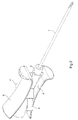
- Figure 2 shows a single take-off needle.
- This needle comprises a single hollow lance 1' adapted for taking off liquid and does not include any part for injecting air.
- the needle of Figure 2 comprises a holding body 3', two spigots 4' connected by an internal pipe of the holding body 3' to the hollow lance 1', and two flanges 6'.
- Figures 3 and 4 are complementary perspective views to show the positioning of the flanges 6 with respect to the holding body 3.
- Each flange 6 is connected onto the holding body 3 via a spacer 7 ensuring rigid fixing as well as spacing of the flanges 6 with respect to the holding body 3.
- each spacer 7 mates with the form of the corresponding flange 6 and holding body 3 and fixes the flange 6 over practically the entirety of the length of the body 3.
- Figures 3 to 7, and more particularly Figure 5, show that the flanges 6 are arcuate such that each of the flanges 6 is bowed towards the holding body 3.
- the flanges 6 consequently have a concave form with respect to the exterior adapted to facilitate grasping of the flanges 6 by the hand of the user.
- the two flanges 6 are disposed on respective sides of the holding body 3 such that each spigot 4 projects between the two flanges 6 (see Figures 5 and 6).
- each flange 6 furthermore has a radius of transverse curvature forming an outwardly directed rounded form.
- This characteristic of a transverse rounded form combines with the arcuate form of the flanges 6 to ensure the user can grasp the needle well by the flanges 6.
- Figures 3, 4 and 5 show that the flanges 6 comprise a guard 8 formed by a tab extending transversely of the corresponding flange 6.
- the guard 8 provides a grip for the user's fingers during the pricking operation.
- each flange 6 has a width slightly greater than the maximum diameter of the holding body 3.
- the flanges 6" are not directly fixed to the holding body 3". More particularly they are each fixed to a half-shell 9 which is then attached to the holding body 3".
- a first step consists of producing an assembly formed from a holding body 3", provided with the hollow lances 1 ", 2" and the spigots 4" (see Figure 9).
- a flange 6" similar to the one described previously is fixed by a spacer 7" to a half-shell 9 which is hermaphrodite in that it is a part comprising an axis of symmetry and comprising pins 10 on one of the lateral edges and corresponding holes 11 on the other of its lateral edges.
- the internal volume of the half-shell 9 reproduces the exterior form of the holding body 3" and of the spigots 4".
- the hollow lances and the spigots may have a different configuration, it being possible for example for the needle to comprise only a single spigot.
Landscapes
- Health & Medical Sciences (AREA)
- Engineering & Computer Science (AREA)
- Life Sciences & Earth Sciences (AREA)
- Public Health (AREA)
- Heart & Thoracic Surgery (AREA)
- Animal Behavior & Ethology (AREA)
- General Health & Medical Sciences (AREA)
- Veterinary Medicine (AREA)
- Biomedical Technology (AREA)
- Surgery (AREA)
- Hematology (AREA)
- Anesthesiology (AREA)
- Vascular Medicine (AREA)
- Mechanical Engineering (AREA)
- Pathology (AREA)
- Medical Informatics (AREA)
- Molecular Biology (AREA)
- Nuclear Medicine, Radiotherapy & Molecular Imaging (AREA)
- Infusion, Injection, And Reservoir Apparatuses (AREA)
- Measurement Of The Respiration, Hearing Ability, Form, And Blood Characteristics Of Living Organisms (AREA)
- Finger-Pressure Massage (AREA)
Abstract
Description
- The invention concerns the general field of take-off needles adapted to be pricked through an elastic wall in order to take off liquid contained in a container closed by the wall.
- The invention more particularly concerns such a take-off needle which comprises a hollow lance generally formed from a fine steel tube provided at its distal end with a sharp pricking tip and connected to a pipe by its proximal end.
- The pricking tip is thus adapted to pass through said elastic wall to enable the liquid to flow in the hollow lance towards the pipe which comprises a spigot to which for example may be connected a tube by which the taken-off liquid will be collected, for example in a container.
- Such needles generally comprise a polymer holding body molded over the proximal end of the hollow lance, the holding body forming an internal channel ensuring the flow of the liquid from the hollow lance to the spigot of the pipe. The holding body also enables the needle to be manipulated, in particular during the pricking operation.
- Such needles are for example used to take off liquid from a bottle closed by a rubber bung. The spigot of the pipe is then connected in advance to a tube leading to a container. Next the needle is pricked into the bung such that the distal end passes through the bung and reaches the medium to be taken-off, the user holding the needle by the holding body.
- The liquid to be taken off then flows to the container, for example by gravity or with the help of a peristaltic pump or else by the pressurization of the bottle containing the liquid.
- Such needles may for example be what is referred to as "single" needles, that is to say that they only comprise a single hollow lance connected to just one pipe; or else they may be what is referred to as "double" needles, that is to say that they comprise a hollow lance of which the flow is divided into two at the holding body to go to two pipes for taking off the liquid simultaneously to two different containers.
- These needles, whether single or double, may be vented, that is to say that they comprise a second hollow lance, of smaller diameter than the main hollow lance, which is inserted in the main hollow lance. This second hollow lance allows the progressive introduction of air into the bottle containing the liquid to take off as the liquid flows in the main hollow lance. Such a vented needle makes it possible to carry out take-off operations from a fluid-tight bottle.
- Such take-off needles are known which are provided to be manipulated directly by the holding body. Although the form of the holding body is defined by its function, i.e. the connection of the hollow lance to the pipe, it may be grasped in the hand by the user to manipulate the take-off needle, in particular to perform the pricking operation, without touching the hollow lance.
- The holding body comprises a cylindrical body extending from the hollow lance and in line therewith. The spigot of the pipe is connected to the cylindrical body so as to project transversely or obliquely. Several spigots may project from the cylindrical body.
- The ergonomic quality of these needles is limited in that the hand of the user must adapt to the forms of the cylindrical body and of the spigot.
- Other take-off needles are known which are adapted to be manipulated by their holding body, as set out above, and which further comprise a guard formed by a plate that is transverse to the cylindrical body of the holding body. The guard is disposed on the holding body in the vicinity of the junction between the cylindrical body and the hollow lance. During the pricking operation, the guard enables the fingers of the user to be held clear of the hollow lance by a physical barrier.
- In particular, during the pricking operation, the guard forms a grip for the user's fingers which thereby avoid the risk of slipping onto the hollow lance.
- The object of the invention is to improve this type of take-off needle by providing a needle which is more ergonomic.
- To that end, the invention is directed to a take-off needle comprising a hollow lance having a distal end adapted to perform a pricking operation, said hollow lance being connected to at least one pipe provided with a spigot for it to be connected to a tube, and comprising a body for holding the hollow lance and pipe relative to each other such that the spigot projects from the holding body, said needle being characterized in that it further comprises two flanges held on respective sides of and spaced from the holding body by virtue of a spacer disposed between each flange and the holding body, said flanges extending in a Innniturlinal direction from the spigot to the vicinity of the proximal end of the hollow lance, the width of each flange being greater than the width of the portion of the holding body facing the flanges.
- In such a take-off needle, the holding body is, as it were, sandwiched between the two flanges. As these flanges transversely cover at least a portion of the holding body, it is much simpler for the user's hand to grasp the needle by both flanges than by the holding body.
- According to a preferred feature, each of the flanges also extends between the spigot and the proximal end of the holding body, to be better held by the hand.
- Each of the flanges may furthermore be arcuate so as to bowed towards the holding body.
- The arcuate form of the flanges provides longitudinal centering of the user's hand with respect to the holding body. The hand intuitively locates around the arcuate flanges and in the concave form which they define.
- For the same reasons, each of the flanges may also have a transverse curvature so as to present a rounded surface.
- The needle according to the invention may further comprise the following advantageous features, either alone or in combination:
- each of the flanges comprises a transverse guard at its distal end;
- the spigot projects from the holding body between the two flanges;
- the needle comprises two spigots projecting on respective sides of the holding body such that each of them projects between the two flanges, the spigot or spigots being thereby protected by the flanges, for example against the tubes connected to those spigots being accidentally pulled off;
- the flanges are attached to the holding body via a shell the internal form of which mates with the external form of the holding body;
- said shell comprises two half-shells each connected to one of the flanges;
- said half-shells are identical and hermaphrodite.
- The invention also relates to a method of manufacturing a take-off needle as presented above, said method comprising the following steps:
- manufacturing an assembly comprising the holding body attached to the hollow lance and to the pipe:
- mounting said half-shells onto the holding body.
- Other features and advantages of the invention appear in the light of the following description of a preferred embodiment, given by way of non-limiting example, and made with reference to the accompanying drawings in which:
- figure 1 is a perspective view of a double take-off needle according to the invention;
- figure 2 is a perspective view of a single take-off needle according to the invention;
- figure 3 is a perspective view of the assembly formed by the holding body provided with its two flanges, of the take-off needle of Figure 1 or Figure 2;
- figure 4 is another perspective view of the assembly of Figure 3;
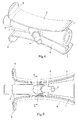
- figure 5 is a side view of the assembly of Figure 3;
- figure 6 is a view from the right of the assembly of Figure 5;
- figure 7 is a view on section line A-A of Figure 5;
- figure 8 is a perspective view of a half-shell provided with a flange; and
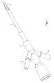
- figure 9 is a perspective view of a take-off needle comprising a holding body onto which can be added two half-shells in accordance with that of Figure 8.
- Figures 1 and 2 each represent a take-off needle in accordance with one embodiment of the invention.
- Figure 1 represents a double take-off needle comprising a main
hollow lance 1 adapted for the passage of the liquid to take off, a ventinghollow lance 2 adapted to inject air into the container containing the liquid to be taken off, aholding body 3 defining an inner pipe which divides into two sub-pipes each provided with aspigot 4. - The liquid taken off flowing in the main
hollow lance 1 may thus be distributed by thespigots 4. - A tube may for example be connected to each of the
spigots 4 in order to collect the liquid taken off in two different containers. - As regards the venting
hollow lance 2, this passes through the inside of theholding body 3 to connect to aventing filter 5 which in the present example enables sterile air to be injected by the ventinghollow lance 2. - This take-off needle further comprises two
flanges 6 attached on respective sides of theholding body 3. - Figure 2 on the other hand shows a single take-off needle. This needle comprises a single hollow lance 1' adapted for taking off liquid and does not include any part for injecting air.
- As with the needle of Figure 1, the needle of Figure 2 comprises a holding body 3', two spigots 4' connected by an internal pipe of the holding body 3' to the hollow lance 1', and two flanges 6'.
- The assembly formed by the
holding body 3, 3', thespigots 4, 4' and theflanges 6, 6' is common to both embodiments of the take-off needle presented here in Figures 1 and 2. This assembly is represented in Figures 3 to 7 and will be described below using the numbering of the parts of Figure 1, it being understood that the assembly represented in Figures 3 to 7 is also adapted to the embodiment of Figure 2. - Figures 3 and 4 are complementary perspective views to show the positioning of the
flanges 6 with respect to theholding body 3. - Each
flange 6 is connected onto theholding body 3 via aspacer 7 ensuring rigid fixing as well as spacing of theflanges 6 with respect to theholding body 3. - As shown in Figure 5, each
spacer 7 mates with the form of thecorresponding flange 6 and holdingbody 3 and fixes theflange 6 over practically the entirety of the length of thebody 3. - The spacing between the
flange 6 and the holdingbody 3 is also visible in Figure 6 as well as on the cross-section in Figure 7. - Figures 3 to 7, and more particularly Figure 5, show that the
flanges 6 are arcuate such that each of theflanges 6 is bowed towards the holdingbody 3. Theflanges 6 consequently have a concave form with respect to the exterior adapted to facilitate grasping of theflanges 6 by the hand of the user. - The two
flanges 6 are disposed on respective sides of the holdingbody 3 such that eachspigot 4 projects between the two flanges 6 (see Figures 5 and 6). - With reference to Figure 4 and Figures 6 and 7, each
flange 6 furthermore has a radius of transverse curvature forming an outwardly directed rounded form. - This characteristic of a transverse rounded form combines with the arcuate form of the
flanges 6 to ensure the user can grasp the needle well by theflanges 6. - Furthermore, Figures 3, 4 and 5 show that the
flanges 6 comprise aguard 8 formed by a tab extending transversely of thecorresponding flange 6. - The
guard 8 provides a grip for the user's fingers during the pricking operation. - As regards the width of the
flanges 6, Figure 6 shows that eachflange 6 has a width slightly greater than the maximum diameter of the holdingbody 3. - In the present example, the assembly of Figures 3 to 7 was produced with the following dimensions:
- minimum diameter of the holding body 3: approximately 7 mm
- maximum diameter of the holding body 3: approximately 13 mm
- thickness of the spacer 7: approximately 1 to 2 mm
- length of the flanges 6: approximately 40 to 50 mm
- minimum separation between the outer surfaces of the flanges 6 (in the proximity of the section line A-A of Figure 5): approximately 15 mm
- radius of curvature of the arcuate form of the flanges 6: approximately 70 to 80 mm
- radius of curvature of the transverse rounded form of the flanges 6: approximately 15 to 20 mm
- width of the flanges 6: approximately 15 mm.
- With reference to Figures 8 and 9, an alternative embodiment of the invention will now be described. The parts of the same nature as in the embodiments of Figures 1 to 7 will bear the same number in Figures 8 and 9 followed by a "second" sign (").
- In this embodiment, the
flanges 6" are not directly fixed to the holdingbody 3". More particularly they are each fixed to a half-shell 9 which is then attached to the holdingbody 3". - On producing such a needle, a first step consists of producing an assembly formed from a holding
body 3", provided with thehollow lances 1 ", 2" and thespigots 4" (see Figure 9). - Two other parts each in accordance with Figure 8 and identical to each other are next produced. These parts each comprise a
flange 6". - With reference to Figure 8, a
flange 6" similar to the one described previously is fixed by aspacer 7" to a half-shell 9 which is hermaphrodite in that it is a part comprising an axis of symmetry and comprisingpins 10 on one of the lateral edges and correspondingholes 11 on the other of its lateral edges. - The internal volume of the half-
shell 9 reproduces the exterior form of the holdingbody 3" and of thespigots 4". - Two parts in accordance with Figure 8 may be assembled together, the
pins 10 of one entering theholes 11 of the other. This assembly is made on the holdingbody 3" such that the latter is trapped between the two half-shells 9. - Once the assembly has been completed, a take-off needle provided with two
flanges 6" rigidly attached to the holdingbody 3" is produced. - Variant embodiments of the take-off needle may be envisaged without departing from the scope of the invention. For example, the hollow lances and the spigots may have a different configuration, it being possible for example for the needle to comprise only a single spigot.
Claims (11)
- A take-off needle comprising a hollow lance (1) having a distal end adapted to perform a pricking operation, said hollow lance (1) being connected to at least one pipe provided with a spigot (4) for it to be connected to a tube, and comprising a body (3) for holding the hollow lance (1) and pipe relative to each other such that the spigot (4) projects from the holding body (3), said needle being characterized in that it further comprises two flanges (6) held on respective sides of and spaced from the holding body (3) by virtue of a spacer (7) disposed between each flange (6) and the holding body (3), said flanges (6) extending in a longitudinal direction from the spigot (4) to the vicinity of the proximal end of the hollow lance (1), the width of each flange (6) being greater than the width of the portion of the holding body (3) facing the flanges (6).
- A take-off needle according to claim 1, characterized in that each of the flanges (6) also extends between the spigot (4) and the proximal end of the holding body (3).
- A take-off needle according to one of claims 1 and 2, characterized in that each of the flanges (6) is arcuate so as to be bowed towards the holding body (3).
- A take-off needle according to one of claims 1 to 3, characterized in that each of the flanges (6) has a transverse curvature so as to present a rounded surface.
- A take-off needle according to one of claims 1 to 4, characterized in that each of the flanges (6) comprises a transverse guard (8) at its distal end.
- A take-off needle according to one of claims 1 to 5, characterized in that the spigot (4) projects from the holding body (3) between the two flanges (6).
- A take-off needle according to claim 6, characterized in that it comprises two spigots (4) projecting on respective sides of the holding body (3) such that each of them projects between the two flanges (6).
- A take-off needle according to one of claims 1 to 7, characterized in that the flanges (6") are attached to the holding body (3") via a shell (9) the internal form of which mates with the external form of the holding body (3").
- A take-off needle according to claim 8, characterized in that said shell comprises two half-shells (9) each connected to one of the flanges (6");
- A take-off needle according to claim 9, characterized in that said half-shells (9) are identical and hermaphrodite.
- A method of manufacturing a take-off needle according to one of claims 9 and 10, characterized in that it comprises the following steps:- manufacturing an assembly comprising the holding body (3") attached to the hollow lance (1") and to the pipe (4");- mounting said half-shells (9) onto the holding body (3").
Applications Claiming Priority (1)
| Application Number | Priority Date | Filing Date | Title |
|---|---|---|---|
| FR0411416A FR2876919B1 (en) | 2004-10-26 | 2004-10-26 | HOLDING NEEDLE HAVING GAME OF GRIPPING. |
Publications (2)
| Publication Number | Publication Date |
|---|---|
| EP1652543A1 true EP1652543A1 (en) | 2006-05-03 |
| EP1652543B1 EP1652543B1 (en) | 2007-08-15 |
Family
ID=34950193
Family Applications (1)
| Application Number | Title | Priority Date | Filing Date |
|---|---|---|---|
| EP05292112A Expired - Lifetime EP1652543B1 (en) | 2004-10-26 | 2005-10-11 | A holding needle comprising gripping flanges |
Country Status (8)
| Country | Link |
|---|---|
| US (2) | US8668673B2 (en) |
| EP (1) | EP1652543B1 (en) |
| JP (1) | JP4810187B2 (en) |
| CN (1) | CN1765426B (en) |
| AT (1) | ATE369886T1 (en) |
| DE (1) | DE602005002004T2 (en) |
| ES (1) | ES2290866T3 (en) |
| FR (1) | FR2876919B1 (en) |
Cited By (1)
| Publication number | Priority date | Publication date | Assignee | Title |
|---|---|---|---|---|
| CN104117114A (en) * | 2014-07-02 | 2014-10-29 | 成都科创佳思科技有限公司 | Injection syringe with two syringe needles |
Families Citing this family (2)
| Publication number | Priority date | Publication date | Assignee | Title |
|---|---|---|---|---|
| FR2876919B1 (en) * | 2004-10-26 | 2007-07-27 | Millipore Corp | HOLDING NEEDLE HAVING GAME OF GRIPPING. |
| CN114180307B (en) * | 2021-12-28 | 2025-08-29 | 迈得医疗工业设备股份有限公司 | Blade face positioning device and medical device production line |
Citations (5)
| Publication number | Priority date | Publication date | Assignee | Title |
|---|---|---|---|---|
| US2893389A (en) * | 1955-03-31 | 1959-07-07 | Baxter Laboratories Inc | Needle hub seal |
| EP0050459A1 (en) * | 1980-10-22 | 1982-04-28 | Travenol European Research and Development Centre (Teradec) | Spike connector |
| EP0591714A2 (en) * | 1992-09-18 | 1994-04-13 | Fresenius AG | Fluid collection device for medical container |
| US5976115A (en) * | 1997-10-09 | 1999-11-02 | B. Braun Medical, Inc. | Blunt cannula spike adapter assembly |
| EP1323403A1 (en) * | 2001-12-17 | 2003-07-02 | Bristol-Myers Squibb Company | Transfer device and cap assembly for use with a container and the transfer device |
Family Cites Families (68)
| Publication number | Priority date | Publication date | Assignee | Title |
|---|---|---|---|---|
| US540797A (en) * | 1895-06-11 | Vehicle-step | ||
| US536696A (en) * | 1895-04-02 | Split rubber wheel | ||
| US1613039A (en) * | 1923-06-19 | 1927-01-04 | Mclaren Automobile Signal Comp | Drill-collar protector |
| US2989053A (en) * | 1956-01-17 | 1961-06-20 | Baxter Don Inc | Hypodermic needle |
| US3429700A (en) * | 1966-09-20 | 1969-02-25 | Teleflex Inc | Method of producing composite metal articles by uniting two identical shapes |
| US3759180A (en) * | 1971-11-01 | 1973-09-18 | E Gibbons | Hollow stamp handle |
| US3757031A (en) * | 1972-05-02 | 1973-09-04 | Thomas & Betts Corp | The like selectively closable protective enclosure for electrical splices and |
| US3893445A (en) * | 1974-01-09 | 1975-07-08 | Becton Dickinson Co | Bone marrow biopsy instrument |
| US4020837A (en) * | 1975-11-04 | 1977-05-03 | Pharmaco, Inc. (Entire) | Hollow piercing tip for vial stoppers |
| US4292405A (en) * | 1978-03-13 | 1981-09-29 | Baxter Travenol Laboratories, Inc. | Sterility test set |
| US4411661A (en) * | 1980-10-22 | 1983-10-25 | Travenol European Research And Development Centre | Spike connector |
| US4351900A (en) * | 1981-01-30 | 1982-09-28 | Millipore Corporation | Test method and apparatus for the presence of microorganisms in ampoule |
| SE425518B (en) * | 1981-03-10 | 1982-10-04 | Electrolux Ab | COMPOSITION BELT DISK |
| US5688254A (en) * | 1983-01-24 | 1997-11-18 | Icu Medical, Inc. | Medical connector |
| US4601710B1 (en) * | 1983-08-24 | 1998-05-05 | United States Surgical Corp | Trocar assembly |
| JPS61106256U (en) * | 1984-12-16 | 1986-07-05 | ||
| US4723955A (en) * | 1986-06-02 | 1988-02-09 | Manresa, Inc. | Suction needle providing vent capability |
| US4857068A (en) * | 1986-12-22 | 1989-08-15 | Miles Laboratories, Inc. | Universal spike for use with rigid and collapsible parenteral fluid dispensing container |
| US4822351A (en) * | 1987-03-25 | 1989-04-18 | Ims Limited | Powder spike holder |
| US4834744A (en) * | 1987-11-04 | 1989-05-30 | Critikon, Inc. | Spike for parenteral solution container |
| US4810244B1 (en) * | 1987-12-17 | 1998-06-16 | Thomas C Allen | Trocar assembly for drawing fluids from a body part |
| US5964785A (en) * | 1988-01-25 | 1999-10-12 | Baxter International Inc. | Bayonet look cannula for pre-slit y-site |
| SE8800337L (en) * | 1988-02-03 | 1989-08-04 | Astra Ab | DEVICE FOR MIXING AND / OR TRANSFER OF A SUBSTANCE |
| US5167635A (en) * | 1989-09-22 | 1992-12-01 | Habley Medical Technology Corporation | Compact, easy to assemble, safety IV system |
| US5030205A (en) * | 1989-12-18 | 1991-07-09 | Critikon, Inc. | Catheter assemblies for prevention of blood leakage |
| US5098394A (en) * | 1990-05-31 | 1992-03-24 | Luther Ronald B | Biased shut off valve assembly for needle and catheter |
| AT397911B (en) * | 1990-07-04 | 1994-08-25 | Avl Verbrennungskraft Messtech | TWO TUMBLE NEEDLE FOR BODY LIQUIDS |
| AT398699B (en) | 1990-07-30 | 1995-01-25 | Avl Verbrennungskraft Messtech | DIALYSIS PROBE |
| US5057058A (en) * | 1990-09-10 | 1991-10-15 | Crudup Jack M | Split pulley |
| DK0479130T3 (en) * | 1990-10-05 | 1995-02-20 | United States Surgical Corp | Safety pads |
| US5226426A (en) * | 1990-12-18 | 1993-07-13 | Inbae Yoon | Safety penetrating instrument |
| FR2671283B1 (en) * | 1991-01-08 | 1995-05-12 | Alain Durand | INTRAVASCULAR MULTI-LIGHT CATHETER, LIKELY TO BE IMPLANTED WITH TUNNELLING. |
| US5378203A (en) * | 1991-04-02 | 1995-01-03 | Ultra Polymer Sciences, Inc. | Mechanical donut and assembly |
| US5295993A (en) * | 1991-04-30 | 1994-03-22 | United States Surgical Corporation | Safety trocar |
| DE4122476A1 (en) | 1991-07-06 | 1993-01-07 | Leopold Pharma Gmbh | Sterile liq. transfer in e.g. medical infusion mixts. - using double, self sealing, spined cannula coupling |
| US5879499A (en) | 1996-06-17 | 1999-03-09 | Heartport, Inc. | Method of manufacture of a multi-lumen catheter |
| US5762629A (en) * | 1991-10-30 | 1998-06-09 | Smith & Nephew, Inc. | Oval cannula assembly and method of use |
| US5312345A (en) * | 1992-03-11 | 1994-05-17 | Cole Richard D | Anti-needle stick protective inner blunt tubular stylet for intravenous therapy |
| JP2740427B2 (en) | 1992-05-25 | 1998-04-15 | 財団法人国際超電導産業技術研究センター | Preparation method of oxide crystal |
| US5224252A (en) * | 1992-07-22 | 1993-07-06 | Baker Jimmy N | Split yarn roll |
| US5603706A (en) * | 1992-09-29 | 1997-02-18 | Wyatt; Philip | Infusion apparatus |
| US5356421A (en) * | 1992-10-07 | 1994-10-18 | United States Surgical Corporation | Safety trocar with locking handles |
| US5334179A (en) * | 1992-10-16 | 1994-08-02 | Abbott Laboratories | Latching piercing pin for use with fluid vials of varying sizes |
| US5407807A (en) | 1993-04-23 | 1995-04-18 | Daymark Medical Industries, Inc. | Method and apparatus for detecting sepsis causation in a catheter |
| US5445630A (en) * | 1993-07-28 | 1995-08-29 | Richmond; Frank M. | Spike with luer fitting |
| US5423796A (en) * | 1993-10-08 | 1995-06-13 | United States Surgical Corporation | Trocar with electrical tissue penetration indicator |
| US5669883A (en) * | 1995-04-12 | 1997-09-23 | Symbiosis Corporation | Veress needle and cannula assembly |
| US5571133A (en) * | 1995-06-01 | 1996-11-05 | Yoon; Inbae | Penetrating instrument with sequential indication of entry into anatomical cavities |
| KR0135178Y1 (en) * | 1995-06-26 | 1999-03-20 | 김인환 | Blood collection lancet |
| CN1194587A (en) * | 1995-07-11 | 1998-09-30 | 奈科姆成像有限公司 | Piercing pin for an infusion system |
| US5785582A (en) * | 1995-12-22 | 1998-07-28 | Flow International Corporation | Split abrasive fluid jet mixing tube and system |
| US6059771A (en) | 1996-12-23 | 2000-05-09 | Johnson & Johnson Medical, Inc. | Stiffening member to increase fluid flow within a medical device |
| US6391414B1 (en) * | 1997-03-07 | 2002-05-21 | Pharmacia Ab | Structure and method for joining parts |
| USD399558S (en) * | 1997-09-05 | 1998-10-13 | Industrie Borla S.P.A. | Piercing cannula body for medical infusion or transfusion lines |
| US5951508A (en) * | 1997-09-29 | 1999-09-14 | Medtronic, Inc. | Bilaterally connectable softshell reservoir |
| US6213978B1 (en) * | 1998-10-27 | 2001-04-10 | Cherie A. Voyten | Intravenous catheter insertion apparatus |
| DE19905644C2 (en) | 1999-02-11 | 2003-03-27 | Sartorius Gmbh | Puncture device for the sterile removal of a liquid medium |
| JP2002070794A (en) * | 2000-09-01 | 2002-03-08 | Minebea Co Ltd | Impeller for axial flow blower |
| US6554809B2 (en) | 2001-08-02 | 2003-04-29 | Teodulo Aves | Epidural catheter needle |
| US6921378B2 (en) * | 2001-10-09 | 2005-07-26 | Boston Scientific Scimed, Inc. | Anti-reflux drainage devices and methods |
| US6740277B2 (en) | 2002-04-24 | 2004-05-25 | Becton Dickinson And Company | Process of making a catheter |
| EP1511528A4 (en) * | 2002-05-16 | 2008-07-02 | Scott Lab Inc | Drug container entry mechanisms and method |
| US7416227B1 (en) * | 2002-10-25 | 2008-08-26 | Earnest William C | Conduit repair apparatus and method |
| US20050033267A1 (en) * | 2003-08-06 | 2005-02-10 | Kimberly-Clark Worldwide, Inc. | Connector with connection mechanism adapted for releasable interconnection with tube |
| FR2876923B1 (en) * | 2004-10-26 | 2007-03-30 | Millipore Corp | DUAL SAMPLE NEEDLE AND METHOD FOR PRODUCING THE SAME |
| FR2876919B1 (en) * | 2004-10-26 | 2007-07-27 | Millipore Corp | HOLDING NEEDLE HAVING GAME OF GRIPPING. |
| US20080140054A1 (en) * | 2006-12-07 | 2008-06-12 | George Lee | Rotating Means For Suction Tube |
| FR2942159B1 (en) * | 2009-02-17 | 2011-03-25 | Jedo Technologies | HIGH PRESSURE LIQUID PROJECTION GUN FOR VERY HIGH PRESSURE LIQUID PROJECTION MACHINE AND METHOD FOR MANUFACTURING THE SAME |
-
2004
- 2004-10-26 FR FR0411416A patent/FR2876919B1/en not_active Expired - Fee Related
-
2005
- 2005-10-11 ES ES05292112T patent/ES2290866T3/en not_active Expired - Lifetime
- 2005-10-11 EP EP05292112A patent/EP1652543B1/en not_active Expired - Lifetime
- 2005-10-11 DE DE602005002004T patent/DE602005002004T2/en not_active Expired - Lifetime
- 2005-10-11 AT AT05292112T patent/ATE369886T1/en not_active IP Right Cessation
- 2005-10-25 JP JP2005309407A patent/JP4810187B2/en not_active Expired - Lifetime
- 2005-10-25 US US11/258,478 patent/US8668673B2/en active Active
- 2005-10-26 CN CN2005101181490A patent/CN1765426B/en not_active Expired - Lifetime
-
2014
- 2014-01-24 US US14/162,823 patent/US9475157B2/en not_active Expired - Lifetime
Patent Citations (5)
| Publication number | Priority date | Publication date | Assignee | Title |
|---|---|---|---|---|
| US2893389A (en) * | 1955-03-31 | 1959-07-07 | Baxter Laboratories Inc | Needle hub seal |
| EP0050459A1 (en) * | 1980-10-22 | 1982-04-28 | Travenol European Research and Development Centre (Teradec) | Spike connector |
| EP0591714A2 (en) * | 1992-09-18 | 1994-04-13 | Fresenius AG | Fluid collection device for medical container |
| US5976115A (en) * | 1997-10-09 | 1999-11-02 | B. Braun Medical, Inc. | Blunt cannula spike adapter assembly |
| EP1323403A1 (en) * | 2001-12-17 | 2003-07-02 | Bristol-Myers Squibb Company | Transfer device and cap assembly for use with a container and the transfer device |
Cited By (1)
| Publication number | Priority date | Publication date | Assignee | Title |
|---|---|---|---|---|
| CN104117114A (en) * | 2014-07-02 | 2014-10-29 | 成都科创佳思科技有限公司 | Injection syringe with two syringe needles |
Also Published As
| Publication number | Publication date |
|---|---|
| JP2006150071A (en) | 2006-06-15 |
| US9475157B2 (en) | 2016-10-25 |
| US20060089047A1 (en) | 2006-04-27 |
| FR2876919B1 (en) | 2007-07-27 |
| US20140137386A1 (en) | 2014-05-22 |
| US8668673B2 (en) | 2014-03-11 |
| EP1652543B1 (en) | 2007-08-15 |
| FR2876919A1 (en) | 2006-04-28 |
| DE602005002004T2 (en) | 2008-05-08 |
| JP4810187B2 (en) | 2011-11-09 |
| ES2290866T3 (en) | 2008-02-16 |
| CN1765426A (en) | 2006-05-03 |
| CN1765426B (en) | 2012-01-18 |
| ATE369886T1 (en) | 2007-09-15 |
| DE602005002004D1 (en) | 2007-09-27 |
Similar Documents
| Publication | Publication Date | Title |
|---|---|---|
| AU2021202622B2 (en) | Blood sample optimization system and blood contaminant sequestration device and method | |
| JP5038369B2 (en) | Guide wire assembly | |
| US9671318B1 (en) | Specimen collector | |
| US20040162540A1 (en) | Transfer device | |
| AU6916294A (en) | Means for collection and transfer of fluids | |
| JP2004000576A (en) | Non-patient needle device and blood collection set | |
| US9475157B2 (en) | Holding needle comprising gripping cheeks | |
| EP2386285A1 (en) | Port device | |
| US7645270B2 (en) | Double take-off needle and method for producing it | |
| US20180056034A1 (en) | Central venous catheter access aspiration system | |
| JP4654102B2 (en) | Protector and needle set | |
| JPS59131332A (en) | Apparatus for sampling body fluids | |
| JP4393885B2 (en) | Guide wire feeder and guide wire inserter | |
| US12440132B2 (en) | Waste tube cartridge for phlebotomy | |
| CN213252040U (en) | Needleless infusion tube joint | |
| CN211155835U (en) | A safe blood gas needle | |
| CN214596059U (en) | Sterile flushing needle convenient to hold | |
| JP2006068100A (en) | Flushing device and catheter set | |
| JP5972812B2 (en) | Liquid injection parts, medical devices and blood bags | |
| KR20150002053A (en) | A Injecting Unit for Preventing Separation | |
| CN215134781U (en) | Medical puncture-preventing infusion apparatus | |
| JP2008023128A (en) | Guidewire supply instrument and guidewire insertion instrument | |
| JP2012135421A (en) | Liquid injection part and medical instrument | |
| US20060258957A1 (en) | Blood drawing system | |
| JPH09140772A (en) | Blood bag and blood collection method |
Legal Events
| Date | Code | Title | Description |
|---|---|---|---|
| PUAI | Public reference made under article 153(3) epc to a published international application that has entered the european phase |
Free format text: ORIGINAL CODE: 0009012 |
|
| AK | Designated contracting states |
Kind code of ref document: A1 Designated state(s): AT BE BG CH CY CZ DE DK EE ES FI FR GB GR HU IE IS IT LI LT LU LV MC NL PL PT RO SE SI SK TR |
|
| AX | Request for extension of the european patent |
Extension state: AL BA HR MK YU |
|
| 17P | Request for examination filed |
Effective date: 20060425 |
|
| 17Q | First examination report despatched |
Effective date: 20060625 |
|
| AKX | Designation fees paid |
Designated state(s): AT BE BG CH CY CZ DE DK EE ES FI FR GB GR HU IE IS IT LI LT LU LV MC NL PL PT RO SE SI SK TR |
|
| GRAP | Despatch of communication of intention to grant a patent |
Free format text: ORIGINAL CODE: EPIDOSNIGR1 |
|
| GRAS | Grant fee paid |
Free format text: ORIGINAL CODE: EPIDOSNIGR3 |
|
| GRAA | (expected) grant |
Free format text: ORIGINAL CODE: 0009210 |
|
| AK | Designated contracting states |
Kind code of ref document: B1 Designated state(s): AT BE BG CH CY CZ DE DK EE ES FI FR GB GR HU IE IS IT LI LT LU LV MC NL PL PT RO SE SI SK TR |
|
| REG | Reference to a national code |
Ref country code: GB Ref legal event code: FG4D |
|
| REG | Reference to a national code |
Ref country code: CH Ref legal event code: EP |
|
| REG | Reference to a national code |
Ref country code: IE Ref legal event code: FG4D |
|
| REF | Corresponds to: |
Ref document number: 602005002004 Country of ref document: DE Date of ref document: 20070927 Kind code of ref document: P |
|
| REG | Reference to a national code |
Ref country code: CH Ref legal event code: NV Representative=s name: KIRKER & CIE S.A. |
|
| ET | Fr: translation filed | ||
| PG25 | Lapsed in a contracting state [announced via postgrant information from national office to epo] |
Ref country code: LT Free format text: LAPSE BECAUSE OF FAILURE TO SUBMIT A TRANSLATION OF THE DESCRIPTION OR TO PAY THE FEE WITHIN THE PRESCRIBED TIME-LIMIT Effective date: 20070815 Ref country code: IS Free format text: LAPSE BECAUSE OF FAILURE TO SUBMIT A TRANSLATION OF THE DESCRIPTION OR TO PAY THE FEE WITHIN THE PRESCRIBED TIME-LIMIT Effective date: 20071215 Ref country code: FI Free format text: LAPSE BECAUSE OF FAILURE TO SUBMIT A TRANSLATION OF THE DESCRIPTION OR TO PAY THE FEE WITHIN THE PRESCRIBED TIME-LIMIT Effective date: 20070815 Ref country code: BG Free format text: LAPSE BECAUSE OF FAILURE TO SUBMIT A TRANSLATION OF THE DESCRIPTION OR TO PAY THE FEE WITHIN THE PRESCRIBED TIME-LIMIT Effective date: 20071115 |
|
| REG | Reference to a national code |
Ref country code: ES Ref legal event code: FG2A Ref document number: 2290866 Country of ref document: ES Kind code of ref document: T3 |
|
| PG25 | Lapsed in a contracting state [announced via postgrant information from national office to epo] |
Ref country code: AT Free format text: LAPSE BECAUSE OF FAILURE TO SUBMIT A TRANSLATION OF THE DESCRIPTION OR TO PAY THE FEE WITHIN THE PRESCRIBED TIME-LIMIT Effective date: 20070815 Ref country code: PL Free format text: LAPSE BECAUSE OF FAILURE TO SUBMIT A TRANSLATION OF THE DESCRIPTION OR TO PAY THE FEE WITHIN THE PRESCRIBED TIME-LIMIT Effective date: 20070815 |
|
| PG25 | Lapsed in a contracting state [announced via postgrant information from national office to epo] |
Ref country code: LV Free format text: LAPSE BECAUSE OF FAILURE TO SUBMIT A TRANSLATION OF THE DESCRIPTION OR TO PAY THE FEE WITHIN THE PRESCRIBED TIME-LIMIT Effective date: 20070815 |
|
| PG25 | Lapsed in a contracting state [announced via postgrant information from national office to epo] |
Ref country code: GR Free format text: LAPSE BECAUSE OF FAILURE TO SUBMIT A TRANSLATION OF THE DESCRIPTION OR TO PAY THE FEE WITHIN THE PRESCRIBED TIME-LIMIT Effective date: 20071116 Ref country code: DK Free format text: LAPSE BECAUSE OF FAILURE TO SUBMIT A TRANSLATION OF THE DESCRIPTION OR TO PAY THE FEE WITHIN THE PRESCRIBED TIME-LIMIT Effective date: 20070815 |
|
| PG25 | Lapsed in a contracting state [announced via postgrant information from national office to epo] |
Ref country code: MC Free format text: LAPSE BECAUSE OF NON-PAYMENT OF DUE FEES Effective date: 20071031 Ref country code: SK Free format text: LAPSE BECAUSE OF FAILURE TO SUBMIT A TRANSLATION OF THE DESCRIPTION OR TO PAY THE FEE WITHIN THE PRESCRIBED TIME-LIMIT Effective date: 20070815 Ref country code: CZ Free format text: LAPSE BECAUSE OF FAILURE TO SUBMIT A TRANSLATION OF THE DESCRIPTION OR TO PAY THE FEE WITHIN THE PRESCRIBED TIME-LIMIT Effective date: 20070815 Ref country code: PT Free format text: LAPSE BECAUSE OF FAILURE TO SUBMIT A TRANSLATION OF THE DESCRIPTION OR TO PAY THE FEE WITHIN THE PRESCRIBED TIME-LIMIT Effective date: 20080115 |
|
| PLBE | No opposition filed within time limit |
Free format text: ORIGINAL CODE: 0009261 |
|
| STAA | Information on the status of an ep patent application or granted ep patent |
Free format text: STATUS: NO OPPOSITION FILED WITHIN TIME LIMIT |
|
| PG25 | Lapsed in a contracting state [announced via postgrant information from national office to epo] |
Ref country code: SE Free format text: LAPSE BECAUSE OF FAILURE TO SUBMIT A TRANSLATION OF THE DESCRIPTION OR TO PAY THE FEE WITHIN THE PRESCRIBED TIME-LIMIT Effective date: 20071115 Ref country code: RO Free format text: LAPSE BECAUSE OF FAILURE TO SUBMIT A TRANSLATION OF THE DESCRIPTION OR TO PAY THE FEE WITHIN THE PRESCRIBED TIME-LIMIT Effective date: 20070815 |
|
| 26N | No opposition filed |
Effective date: 20080516 |
|
| PG25 | Lapsed in a contracting state [announced via postgrant information from national office to epo] |
Ref country code: IE Free format text: LAPSE BECAUSE OF NON-PAYMENT OF DUE FEES Effective date: 20071011 |
|
| PG25 | Lapsed in a contracting state [announced via postgrant information from national office to epo] |
Ref country code: EE Free format text: LAPSE BECAUSE OF FAILURE TO SUBMIT A TRANSLATION OF THE DESCRIPTION OR TO PAY THE FEE WITHIN THE PRESCRIBED TIME-LIMIT Effective date: 20070815 |
|
| PG25 | Lapsed in a contracting state [announced via postgrant information from national office to epo] |
Ref country code: SI Free format text: LAPSE BECAUSE OF FAILURE TO SUBMIT A TRANSLATION OF THE DESCRIPTION OR TO PAY THE FEE WITHIN THE PRESCRIBED TIME-LIMIT Effective date: 20070815 |
|
| PG25 | Lapsed in a contracting state [announced via postgrant information from national office to epo] |
Ref country code: CY Free format text: LAPSE BECAUSE OF FAILURE TO SUBMIT A TRANSLATION OF THE DESCRIPTION OR TO PAY THE FEE WITHIN THE PRESCRIBED TIME-LIMIT Effective date: 20070815 |
|
| PG25 | Lapsed in a contracting state [announced via postgrant information from national office to epo] |
Ref country code: LU Free format text: LAPSE BECAUSE OF NON-PAYMENT OF DUE FEES Effective date: 20071011 |
|
| PG25 | Lapsed in a contracting state [announced via postgrant information from national office to epo] |
Ref country code: HU Free format text: LAPSE BECAUSE OF FAILURE TO SUBMIT A TRANSLATION OF THE DESCRIPTION OR TO PAY THE FEE WITHIN THE PRESCRIBED TIME-LIMIT Effective date: 20080216 Ref country code: TR Free format text: LAPSE BECAUSE OF FAILURE TO SUBMIT A TRANSLATION OF THE DESCRIPTION OR TO PAY THE FEE WITHIN THE PRESCRIBED TIME-LIMIT Effective date: 20070815 |
|
| PG25 | Lapsed in a contracting state [announced via postgrant information from national office to epo] |
Ref country code: IT Free format text: LAPSE BECAUSE OF NON-PAYMENT OF DUE FEES Effective date: 20071031 |
|
| REG | Reference to a national code |
Ref country code: CH Ref legal event code: PFA Owner name: EMD MILLIPORE CORPORATION Free format text: MILLIPORE CORPORATION#290 CONCORD ROAD#BILLERICA MASSACHUSETTS 01821 (US) -TRANSFER TO- EMD MILLIPORE CORPORATION#290 CONCORD ROAD#BILLERICA, MA 01821 (US) |
|
| REG | Reference to a national code |
Ref country code: NL Ref legal event code: TD Effective date: 20120227 |
|
| REG | Reference to a national code |
Ref country code: ES Ref legal event code: PC2A Owner name: EMD MILLIPORE CORPORATION Effective date: 20120416 |
|
| REG | Reference to a national code |
Ref country code: FR Ref legal event code: CD Owner name: EMD MILLIPORE CORPORATION Effective date: 20120327 |
|
| REG | Reference to a national code |
Ref country code: DE Ref legal event code: R082 Ref document number: 602005002004 Country of ref document: DE Representative=s name: HENKEL, BREUER & PARTNER, DE |
|
| REG | Reference to a national code |
Ref country code: DE Ref legal event code: R082 Ref document number: 602005002004 Country of ref document: DE Representative=s name: PATENTANWAELTE HENKEL, BREUER & PARTNER, DE Effective date: 20120613 Ref country code: DE Ref legal event code: R081 Ref document number: 602005002004 Country of ref document: DE Owner name: EMD MILLIPORE CORPORATION, BILLERICA, US Free format text: FORMER OWNER: MILLIPORE CORP., BILLERICA, MASS., US Effective date: 20120613 |
|
| REG | Reference to a national code |
Ref country code: FR Ref legal event code: PLFP Year of fee payment: 12 |
|
| REG | Reference to a national code |
Ref country code: FR Ref legal event code: PLFP Year of fee payment: 13 |
|
| REG | Reference to a national code |
Ref country code: FR Ref legal event code: PLFP Year of fee payment: 14 |
|
| P01 | Opt-out of the competence of the unified patent court (upc) registered |
Effective date: 20230602 |
|
| PGFP | Annual fee paid to national office [announced via postgrant information from national office to epo] |
Ref country code: GB Payment date: 20240905 Year of fee payment: 20 |
|
| PGFP | Annual fee paid to national office [announced via postgrant information from national office to epo] |
Ref country code: BE Payment date: 20240917 Year of fee payment: 20 |
|
| PGFP | Annual fee paid to national office [announced via postgrant information from national office to epo] |
Ref country code: FR Payment date: 20240909 Year of fee payment: 20 |
|
| PGFP | Annual fee paid to national office [announced via postgrant information from national office to epo] |
Ref country code: NL Payment date: 20240917 Year of fee payment: 20 |
|
| PGFP | Annual fee paid to national office [announced via postgrant information from national office to epo] |
Ref country code: DE Payment date: 20240904 Year of fee payment: 20 |
|
| PGFP | Annual fee paid to national office [announced via postgrant information from national office to epo] |
Ref country code: ES Payment date: 20241101 Year of fee payment: 20 |
|
| PGFP | Annual fee paid to national office [announced via postgrant information from national office to epo] |
Ref country code: CH Payment date: 20241101 Year of fee payment: 20 |
|
| REG | Reference to a national code |
Ref country code: DE Ref legal event code: R071 Ref document number: 602005002004 Country of ref document: DE Ref country code: CH Ref legal event code: H14 Free format text: ST27 STATUS EVENT CODE: U-0-0-H10-H14 (AS PROVIDED BY THE NATIONAL OFFICE) Effective date: 20251011 |
|
| REG | Reference to a national code |
Ref country code: NL Ref legal event code: MK Effective date: 20251010 |
|
| REG | Reference to a national code |
Ref country code: ES Ref legal event code: FD2A Effective date: 20251024 |
|
| REG | Reference to a national code |
Ref country code: GB Ref legal event code: PE20 Expiry date: 20251010 |
|
| REG | Reference to a national code |
Ref country code: BE Ref legal event code: MK Effective date: 20251011 |
|
| PG25 | Lapsed in a contracting state [announced via postgrant information from national office to epo] |
Ref country code: ES Free format text: LAPSE BECAUSE OF EXPIRATION OF PROTECTION Effective date: 20251012 |