EP1652409B1 - Soft light fixture - Google Patents
Soft light fixture Download PDFInfo
- Publication number
- EP1652409B1 EP1652409B1 EP04756537A EP04756537A EP1652409B1 EP 1652409 B1 EP1652409 B1 EP 1652409B1 EP 04756537 A EP04756537 A EP 04756537A EP 04756537 A EP04756537 A EP 04756537A EP 1652409 B1 EP1652409 B1 EP 1652409B1
- Authority
- EP
- European Patent Office
- Prior art keywords
- light
- fixture
- lens
- mixing chamber
- ring
- Prior art date
- Legal status (The legal status is an assumption and is not a legal conclusion. Google has not performed a legal analysis and makes no representation as to the accuracy of the status listed.)
- Expired - Lifetime
Links
Images




Classifications
-
- F—MECHANICAL ENGINEERING; LIGHTING; HEATING; WEAPONS; BLASTING
- F21—LIGHTING
- F21S—NON-PORTABLE LIGHTING DEVICES; SYSTEMS THEREOF; VEHICLE LIGHTING DEVICES SPECIALLY ADAPTED FOR VEHICLE EXTERIORS
- F21S10/00—Lighting devices or systems producing a varying lighting effect
- F21S10/02—Lighting devices or systems producing a varying lighting effect changing colors
-
- F—MECHANICAL ENGINEERING; LIGHTING; HEATING; WEAPONS; BLASTING
- F21—LIGHTING
- F21Y—INDEXING SCHEME ASSOCIATED WITH SUBCLASSES F21K, F21L, F21S and F21V, RELATING TO THE FORM OR THE KIND OF THE LIGHT SOURCES OR OF THE COLOUR OF THE LIGHT EMITTED
- F21Y2103/00—Elongate light sources, e.g. fluorescent tubes
- F21Y2103/30—Elongate light sources, e.g. fluorescent tubes curved
- F21Y2103/33—Elongate light sources, e.g. fluorescent tubes curved annular
-
- F—MECHANICAL ENGINEERING; LIGHTING; HEATING; WEAPONS; BLASTING
- F21—LIGHTING
- F21Y—INDEXING SCHEME ASSOCIATED WITH SUBCLASSES F21K, F21L, F21S and F21V, RELATING TO THE FORM OR THE KIND OF THE LIGHT SOURCES OR OF THE COLOUR OF THE LIGHT EMITTED
- F21Y2107/00—Light sources with three-dimensionally disposed light-generating elements
- F21Y2107/10—Light sources with three-dimensionally disposed light-generating elements on concave supports or substrates, e.g. on the inner side of bowl-shaped supports
-
- F—MECHANICAL ENGINEERING; LIGHTING; HEATING; WEAPONS; BLASTING
- F21—LIGHTING
- F21Y—INDEXING SCHEME ASSOCIATED WITH SUBCLASSES F21K, F21L, F21S and F21V, RELATING TO THE FORM OR THE KIND OF THE LIGHT SOURCES OR OF THE COLOUR OF THE LIGHT EMITTED
- F21Y2113/00—Combination of light sources
- F21Y2113/10—Combination of light sources of different colours
- F21Y2113/13—Combination of light sources of different colours comprising an assembly of point-like light sources
-
- F—MECHANICAL ENGINEERING; LIGHTING; HEATING; WEAPONS; BLASTING
- F21—LIGHTING
- F21Y—INDEXING SCHEME ASSOCIATED WITH SUBCLASSES F21K, F21L, F21S and F21V, RELATING TO THE FORM OR THE KIND OF THE LIGHT SOURCES OR OF THE COLOUR OF THE LIGHT EMITTED
- F21Y2115/00—Light-generating elements of semiconductor light sources
- F21Y2115/10—Light-emitting diodes [LED]
-
- H—ELECTRICITY
- H05—ELECTRIC TECHNIQUES NOT OTHERWISE PROVIDED FOR
- H05K—PRINTED CIRCUITS; CASINGS OR CONSTRUCTIONAL DETAILS OF ELECTRIC APPARATUS; MANUFACTURE OF ASSEMBLAGES OF ELECTRICAL COMPONENTS
- H05K1/00—Printed circuits
- H05K1/18—Printed circuits structurally associated with non-printed electric components
- H05K1/189—Printed circuits structurally associated with non-printed electric components characterised by the use of flexible or folded printed circuits
-
- Y—GENERAL TAGGING OF NEW TECHNOLOGICAL DEVELOPMENTS; GENERAL TAGGING OF CROSS-SECTIONAL TECHNOLOGIES SPANNING OVER SEVERAL SECTIONS OF THE IPC; TECHNICAL SUBJECTS COVERED BY FORMER USPC CROSS-REFERENCE ART COLLECTIONS [XRACs] AND DIGESTS
- Y10—TECHNICAL SUBJECTS COVERED BY FORMER USPC
- Y10S—TECHNICAL SUBJECTS COVERED BY FORMER USPC CROSS-REFERENCE ART COLLECTIONS [XRACs] AND DIGESTS
- Y10S362/00—Illumination
- Y10S362/80—Light emitting diode
Landscapes
- Engineering & Computer Science (AREA)
- General Engineering & Computer Science (AREA)
- Non-Portable Lighting Devices Or Systems Thereof (AREA)
- Fastening Of Light Sources Or Lamp Holders (AREA)
- Luminescent Compositions (AREA)
Abstract
Description
- The present invention is a soft light fixture. In particular, it is an LED soft light fixture.
- Generally, various light fixtures that use light from a combination of light sources are known including
U.S. Patent Nos. 4,280,171 ,4,831,755 . and6.149,283 . - Often, prior art devices that rely on the light from a combination of light sources show "hot spots." In particular, prior art light fixtures using light emitting diodes ("LEDs") use a large number of LEDs to generate the desired amount and color of light. However, typically, the points at which each individual LED are mounted are usually markedly visible as "hot spots" rather than the light of all the LEDs blending together to form a uniform glow.
-
US-A-6,149,283 discloses a LED lamp with several lights mounted on a ring and a pebbled reflector that mixes light from the LEDs to create white or coloured light. - Thus, a light fixture that uses a minimum of LEDs to generate a single light source without "hot spots" is desired. Moreover, a light fixture that blends light from different color LEDs into a single blended light source, e.g. of a new color, is desirable as well.
- The present invention is a soft light fixture. In particular, it is a LED soft light fixture. The preferred embodiment of the soft light fixture has a plurality of light emitting diodes mounted on a printed circuit board ring and seated on a perimeter ring. The LEDs are aimed to emit light into a light mixing chamber. The perimeter ring supports a light deflection cap with a lens, preferably translucent. The perimeter ring, deflection cap and lens define the light mixing chamber which blends light from the plurality of light emitting diodes into a single light source. The lens preferably has a skirt that contains the printed circuit board ring, perimeter ring, and deflection cap.
- Accordingly, the present invention provides a soft light fixture and a method for creating a soft light fixture as described in the appended claims.
- The objects and features of the present invention, which are believed to be novel, are set forth with particularity in the appended claims. The present invention, both as to its organization and manner of operation, together with further objects and advantages, may best be understood by reference to the following description, taken in connection with the accompanying drawings.
- Figure la is an exploded perspective view of a preferred embodiment of the present invention.
-
Figure 1b is an exploded perspective view of an alternative embodiment of the present invention. -
Figure 2a is a side view of a preferred embodiment of the perimeter ring. -
Figure 2b is a side cross-sectional view of a preferred embodiment of the perimeter ring. -
Figure 2c is a top view of a preferred embodiment of the perimeter ring. -
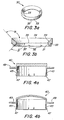
Figure 3a is a perspective view of a preferred embodiment of the deflection cap. -
Figure 3b is a side cross-sectional view of a preferred embodiment of the deflection cap. -
Figure 4a is a side view of an alternate embodiment of the lens. -
Figure 4b is a side view of an alternate embodiment of the lens. -
Figure 4c is a side view of an alternate embodiment of the lens. -
Figure 4d is a side view of an alternate embodiment of the lens. -
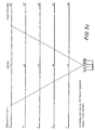
Figures 5a ,5b , and5c are graphs of light intensity, beam diameter as a function of distance from the lens of the present invention. -
Figure 6 is a preferred embodiment of an unmounted LED for use with the present invention. -
Figure 7 is a preferred embodiment of a printed circuit board ring for use with the present invention. -
- [1] The following description is provided to enable any person skilled in the art to make and use the invention and sets forth the best modes contemplated by the inventor of carrying out his invention. Various modifications, however, will remain readily apparent to those skilled in the art, since the general principles of the present invention have been defined herein specifically to provide a soft light fixture.
- [2] Referring now to
Figure 1a , an exploded perspective view of a preferred embodiment of asoft light fixture 10 is shown. Thesoft light fixture 10 preferably comprises aperimeter ring 20 having a plurality ofnotches 22 for lights. A preferred embodiment of thering 20 is shown inFigures 2a, 2b and 2c . There are nine (9)notches 22 shown inFigure 2c . Returning toFigure 1a , a number oflights 25, preferably light emitting diodes (LEDs), are mounted on a printed circuit board (PCB)ring 60. ThePCB ring 60 is preferably flexible and has twoleads 65 for connection to a power source (not shown.) EachLED 25 in turn is seated in acorresponding notch 22 on theperimeter ring 20. Alternatively, each LED can be hard-wired to thefixture 10 instead of using a PCB ring. - [3] Preferably, each
PCB ring 60 has a separate circuit for different sets of LEDs. For example, inFigure 7 , thePCB ring 60 has threeseparate circuits light fixture 10. - [4] By using separate circuits on the
PCB ring 60, the PCB ring can have a set ofleads 65 for each circuit. Thus, each circuit and set of LEDs can be controlled separately, e.g. dimming or powered higher using a simple dimmer or more sophisticated DMX controller. - [5] The
perimeter ring 20 supports adeflection ring 30. Theperimeter ring 20 anddeflection ring 30 are preferably made of white polycarbonate plastic. Referring toFigure 2c , theperimeter ring 20 has aninterior diameter 25 that is less than the diameter of theperimeter ring 20. The progression from the diameter of theperimeter ring 20 to theinterior diameter 25 shown inFigure 2b is aperimeter slope 29. Preferably, an angle (alpha prime, α') is formed between theperimeter slope 20 and theinterior diameter 25. The angle α' is preferably forty-five degrees (45°). - [6] The
perimeter ring 20 preferably has at least onepost 27. Referring now toFigures 3a and 3b , a preferred embodiment of the deflection ring is shown.Figure 3b shows a cross-section of a preferred embodiment of thedeflection ring 30. Thedeflection ring 30 preferably has at least onepost port 33 that receives apost 27 on theperimeter ring 20. Thedeflection ring 30 mounted on theperimeter ring 20 defines a light-mixing chamber. Thedeflection ring 30 further comprisesnotches 32 that align with thenotches 22 on theperimeter ring 20 to define light ports forseating lights 25, e.g. LEDs. Each light 25 is preferably aimed to cast light into the light mixing chamber. - [7] A
lens 40 tops thedeflection ring 30. As shown inFigures 1a ,4a and 4b , thelens 40 can have askirt 45 extending down to contain theperimeter ring 20 anddeflection ring 30. Preferably, theskirt 45 comprisestabs 47 arrange along an edge of theskirt 45. Alternately, thetabs 47 can be located on theperimeter ring 20. Regardless of their location, thetabs 47 are generally used to assist in assembling the fixture and/or waterproofing the fixture. Alternatively, one of thelenses 40, shown inFigures 4c and 4d , can be mounted on thedeflection ring 30. Thelens 40 can be flat as shown inFigure 4c or concave/convex as shown inFigure 4d . Preferably, thelens 40 is made of translucent white polycarbonate or translucent white acrylic plastic. - [8] As shown in
Figure 1a , afastener ring 50 withfastener ports 55 can be used to hold thelens 40 together with thedeflection ring 30 andperimeter ring 20 or mount thefixture 10 to a surface, e.g. a wall, chair, or floor.Figures 1b ,4a and 4b show an alternative embodiment of thelens 40 with aflange 49. Theflange 49 can be used to mount thefixture 10 to other external fixture housings. - [9] Referring to
Figures 3a and 3b , thedeflection ring 30 has aninterior diameter 35 that is less than the diameter of theperimeter ring 20. Preferably, the deflection ring's interior surface slopes to theinterior diameter 35. This progression to theinterior diameter 35 creates adeflection slope 39 that deflects light from theLEDs 25 into the light mixing chamber. Preferably, thedeflection slope 39 extended forms an angle (alpha, α) at least 135 degrees from atop diameter 34 of thedeflection ring 30. - [10] Conversely, the
interior diameter 35 is less than alower diameter 37. This progression from thelower diameter 37 to theinterior diameter 35 shown inFigure 3b isnotch slope 31. Preferably, thenotch slope 31 extended forms an angle (beta, β) of 135° from thelower diameter 37 of thedeflection ring 30. Thus, theLEDs 25 are generally obscured from direct view by theslope 39 of thedeflection ring 30. Instead, the light from the LEDs is reflected into the light-mixing chamber defined by the above-described components to produce a soft light visible to a viewer without "hot spots." - [11] It should be noted that the present invention generates consistent lighting out to the outer edge of the
fixture 10. Thefixture 10, in general, does not have, what is commonly called a "trim ring," namely a dark ring along the edge of thelens 40. Thus, thefastener ring 50 is not used to hide a dark ring at the edge of thelens 40 but, instead, is used for mounting purposes and other reasons described above. - [12] Referring now to
Figures 5a-5c , thisinvention 10 provides a soft light of an intensity useful in a number of applications.Figures 5a-5c show graphs of beam spread and intensity as functions of distance from thefixture 10. Referring toFigure 6 , preferably, the LEDs are 20-40 milliamps (ma) light emitting diodes. If white light is desired, then only white LEDs are mounted in thenotches 22 defined by the perimeter and deflection rings. Alternately, using a combination of colored LEDs mounted in thenotches 22 can create soft lighting with a variety of colors. For example, if a "pink-ish" light is desired, six red LEDs and three white LEDs could be mounted on thePCB ring 60 in order to cast a pink-ish light from thedevice 10. Another alternative is to color thelens 40 the desired color or use a colored gel with thefixture 10. - [13] One preferred embodiment of the invention as described above uses three sets of three LEDs. Thus, combinations of LEDs are preferably based on multiples of three, e.g. three red LEDs and six white LEDs or six red LEDs and three white LEDs. The different circuits on the
PCB ring 60 can also vary the color of light emitted by thefixture 10. For example, two sets of three LEDs could run at 20 milliamps while a third set runs at 40 milliamps. The resistors for each circuit could also be changed to vary the power, brightness and intensity of the LEDs as well. - [14] The present invention provides an improved color consistency over the prior art as well. Typically, when dies of LEDs are produced, the LEDs are sorted into bins by a number of criteria including a large range of "acceptable" colors, or wavelengths, intensity and forward voltage. The LEDs, depending on tolerance for color variation, can be sorted several more times to isolated colors within ranges of 1-3 nanometers in wavelength. However, isolating LEDs of a color with 1 nanometer of wavelength can be very expensive. The present invention allows LEDs of a wider variation in wavelength to be used and their light mixed to produce a single color light and thus hide slight variations in color between LEDs.
- [15] Thus, a soft light fixture is described above that uses a minimum of LEDs to generate a single light source without "hot spots" is described. Moreover, a light fixture that blends light from different color LEDs into a single blended light source of a new color is described as well. In each of the above embodiments, the different positions and structures of the present invention are described separately in each of the embodiments. However, it is the full intention of the inventors of the present invention that the separate aspects of each embodiment described herein may be combined with the other embodiments described herein. Those skilled in the art will appreciate that adaptations and modifications of the just-described preferred embodiment can be configured without departing from the scope and spirit of the invention. Therefore, it is to be understood that, within the scope of the appended claims, the invention may be practiced other than as specifically described herein.
Claims (16)
- A soft light fixture (10) comprising:a plurality of lights mounted on a perimeter structure (20), the structure supporting a light deflection cap (30) that deflects light from the lights into a light mixing chamber; characterised in that the structure and cap surround the light mixing chamber; and,where at least one side of the light mixing chamber is covered by a lens (40).
- The light fixture of Claim 1 where the plurality of lights are light emitting diodes.
- The light fixture of Claim 1 where the perimeter structure has an interior diameter greater than an interior diameter (35) of the light deflection cap.
- The light fixture of Claim 1 where the lens and the light mixing chamber blend light from the plurality of lights into a single light source.
- The light fixture of Claim 4 where the lens has a perimeter edge and the single light source casts light to the perimeter edge of the lens.
- The fixture of Claims 1 to 5 comprising a plurality of light emitting diodes mounted on the perimeter structure.
- The light fixture of any preceding claim where the perimeter structure is a ring.
- The light fixture of any preceding claim where the lens is translucent.
- The light fixture of Claim 6 where the plurality of light emitting diodes comprise diodes of at least two different colors.
- The light fixture of Claim 9 where the mixing chamber, light deflection cap and lens blend the light from diodes of at least two different colors into a single light source of a third color.
- The light fixture of any preceding claim where at least one side of the lens is convex.
- The light fixture of any preceding claim
where the perimeter ring and light deflection cap further define a plurality of light ports containing a light emitting diode in each light port aimed to cast light into the light mixing chamber;
each light emitting diode is mounted to a flexible printed circuit board ring (60); and,
where the lens covers at least one side of the light mixing chamber whereby the lens, the light deflection cap, and the light mixing chamber blend light from the plurality of light emitting diodes into a single light source. - The light fixture of any preceding claim where the light deflection cap further comprises an interior diameter (35) less than a diameter of the perimeter structure.
- The light fixture of Claim 13 where the interior diameter of the light deflection cap forms at most a 135-degree angle with a top diameter of the light deflection cap.
- The light fixture of any preceding claim where the perimeter structure, light deflection cap and the lens are made from white polycarbonate plastic.
- A method for creating a soft light fixture that casts a soft predetermined color of light comprising the following steps:choosing a color of light to be cast from the light fixture;mounting a combination of light emitting diodes on a printed circuit board ring (60) to generate the color of light; characterised byseating the combination of light emitting diodes in a plurality of light ports of a light fixture (10) to produce a light mixing chamber surrounded by a perimeter structure (20), a deflection cap (30) and a lens (40).
Applications Claiming Priority (2)
| Application Number | Priority Date | Filing Date | Title |
|---|---|---|---|
| US10/613,906 US7063441B2 (en) | 2003-07-02 | 2003-07-02 | Soft light fixture |
| PCT/US2004/021213 WO2005006815A2 (en) | 2003-07-02 | 2004-06-30 | Soft light fixture |
Publications (2)
| Publication Number | Publication Date |
|---|---|
| EP1652409A2 EP1652409A2 (en) | 2006-05-03 |
| EP1652409B1 true EP1652409B1 (en) | 2008-07-02 |
Family
ID=33552796
Family Applications (1)
| Application Number | Title | Priority Date | Filing Date |
|---|---|---|---|
| EP04756537A Expired - Lifetime EP1652409B1 (en) | 2003-07-02 | 2004-06-30 | Soft light fixture |
Country Status (5)
| Country | Link |
|---|---|
| US (1) | US7063441B2 (en) |
| EP (1) | EP1652409B1 (en) |
| AT (1) | ATE400162T1 (en) |
| DE (1) | DE602004014781D1 (en) |
| WO (1) | WO2005006815A2 (en) |
Families Citing this family (46)
| Publication number | Priority date | Publication date | Assignee | Title |
|---|---|---|---|---|
| USD537744S1 (en) * | 2004-11-30 | 2007-03-06 | Shih-Hsiung Wu | Ring cover for a vehicle gage |
| US7950824B2 (en) | 2006-05-22 | 2011-05-31 | Koninklijke Philips Electronics N.V. | Lighting system and a color indicator part therefor |
| US7618163B2 (en) * | 2007-04-02 | 2009-11-17 | Ruud Lighting, Inc. | Light-directing LED apparatus |
| WO2008142638A1 (en) | 2007-05-24 | 2008-11-27 | Koninklijke Philips Electronics N.V. | Color-tunable illumination system |
| TW200933075A (en) * | 2008-01-21 | 2009-08-01 | Jiahn-Chang Wu | Reflection type lamp |
| US8763258B2 (en) * | 2008-01-31 | 2014-07-01 | Black & Decker Inc. | Portable band saw |
| USD581081S1 (en) * | 2008-05-05 | 2008-11-18 | Genlyte Thomas Group Llc | LED luminaire |
| US8348475B2 (en) | 2008-05-23 | 2013-01-08 | Ruud Lighting, Inc. | Lens with controlled backlight management |
| US8388193B2 (en) | 2008-05-23 | 2013-03-05 | Ruud Lighting, Inc. | Lens with TIR for off-axial light distribution |
| US9423096B2 (en) | 2008-05-23 | 2016-08-23 | Cree, Inc. | LED lighting apparatus |
| US7841750B2 (en) | 2008-08-01 | 2010-11-30 | Ruud Lighting, Inc. | Light-directing lensing member with improved angled light distribution |
| CN101749571A (en) * | 2008-12-12 | 2010-06-23 | 鸿富锦精密工业(深圳)有限公司 | Light source module |
| TWI410588B (en) * | 2008-12-26 | 2013-10-01 | Hon Hai Prec Ind Co Ltd | Light source module |
| US9255686B2 (en) | 2009-05-29 | 2016-02-09 | Cree, Inc. | Multi-lens LED-array optic system |
| US20110024593A1 (en) * | 2009-07-29 | 2011-02-03 | Vode Lighting Llc | Fixture support system and method |
| USD647227S1 (en) * | 2009-08-03 | 2011-10-18 | Eveready Battery Company, Inc. | Lighting device |
| CN102575812A (en) * | 2009-08-07 | 2012-07-11 | 东芝照明技术株式会社 | Light source unit, light source device, and illumination device |
| USD681867S1 (en) * | 2011-03-11 | 2013-05-07 | GE Lighting Solutions, LLC | Suspended luminaire |
| USD711582S1 (en) * | 2011-09-28 | 2014-08-19 | Wavesquare Inc. | Lighting element |
| US10408429B2 (en) | 2012-02-29 | 2019-09-10 | Ideal Industries Lighting Llc | Lens for preferential-side distribution |
| US9541258B2 (en) | 2012-02-29 | 2017-01-10 | Cree, Inc. | Lens for wide lateral-angle distribution |
| US9541257B2 (en) | 2012-02-29 | 2017-01-10 | Cree, Inc. | Lens for primarily-elongate light distribution |
| USD697664S1 (en) | 2012-05-07 | 2014-01-14 | Cree, Inc. | LED lens |
| USD700992S1 (en) * | 2012-08-28 | 2014-03-11 | Ingenuity Inventions, LLC | Flashing light assembly |
| US9115857B2 (en) * | 2012-10-26 | 2015-08-25 | Mind Head Llc | LED directional lighting system with light intensity controller |
| US9194554B2 (en) | 2013-03-15 | 2015-11-24 | Feit Electric Company, Inc. | LED lighting fixture assembly |
| USD718490S1 (en) | 2013-03-15 | 2014-11-25 | Cree, Inc. | LED lens |
| USD729730S1 (en) * | 2013-06-06 | 2015-05-19 | Jon Simon Gillespie-Brown | Power charging ring |
| US10429052B2 (en) | 2013-10-24 | 2019-10-01 | Feit Electric Company, Inc. | LED lighting fixture |
| US9523479B2 (en) | 2014-01-03 | 2016-12-20 | Cree, Inc. | LED lens |
| US9648688B2 (en) | 2014-03-26 | 2017-05-09 | Mind Head Llc | Security lighting systems for perimeter security including infrared and LED lights and light intensity controllers |
| CA2892456C (en) * | 2014-05-20 | 2017-09-26 | Shane Jacobson | Manhole lighting system |
| RU2017105819A (en) * | 2014-07-24 | 2018-08-28 | Филипс Лайтинг Холдинг Б.В. | LIGHT-RADIATING MODULE |
| JP6964321B2 (en) * | 2015-10-19 | 2021-11-10 | スージョウ レキン セミコンダクター カンパニー リミテッド | Lighting device |
| USD826466S1 (en) | 2017-03-31 | 2018-08-21 | Abl Ip Holding Llc | Light fixture |
| USD829364S1 (en) | 2017-03-31 | 2018-09-25 | Abl Ip Holding Llc | Light fixture |
| USD827912S1 (en) | 2017-03-31 | 2018-09-04 | Abl Ip Holding Llc | Light fixture |
| USD827914S1 (en) * | 2017-03-31 | 2018-09-04 | Abl Ip Holding Llc | Light fixture |
| US10746387B2 (en) | 2017-03-31 | 2020-08-18 | Mind Head Llc | Low voltage security lighting systems for perimeter fences having tactical glare capabilities |
| USD829968S1 (en) | 2017-03-31 | 2018-10-02 | Abl Ip Holding Llc | Light fixture |
| USD829366S1 (en) | 2017-03-31 | 2018-09-25 | Abl Ip Holding Llc | Light fixture |
| USD829365S1 (en) * | 2017-03-31 | 2018-09-25 | Abl Ip Holding Llc | Light fixture |
| USD829367S1 (en) | 2017-03-31 | 2018-09-25 | Abl Ip Holding Llc | Light fixture |
| US10468566B2 (en) | 2017-04-10 | 2019-11-05 | Ideal Industries Lighting Llc | Hybrid lens for controlled light distribution |
| WO2021165174A1 (en) * | 2020-02-18 | 2021-08-26 | Signify Holding B.V. | A light mixing chamber and a luminaire |
| PL74350Y1 (en) * | 2023-04-17 | 2026-04-20 | Nowodvorski Lighting Spółka Z Ograniczoną Odpowiedzialnością | Lamp with an apparent second light source |
Family Cites Families (17)
| Publication number | Priority date | Publication date | Assignee | Title |
|---|---|---|---|---|
| US1318263A (en) | 1919-10-07 | caccese | ||
| US1365027A (en) | 1920-03-19 | 1921-01-11 | Holway D Farrar | Lighting-fixture |
| US1838789A (en) | 1930-04-24 | 1931-12-29 | Schepperle Gottlob | Direction indicator |
| US2119734A (en) | 1936-03-13 | 1938-06-07 | Fred S Caldwell | Headlight for vehicles |
| CH1923970A4 (en) | 1970-12-28 | 1973-12-14 | ||
| US4280171A (en) | 1979-10-01 | 1981-07-21 | Huang Thomas N | Decorative specular illuminator |
| US4831755A (en) | 1987-08-24 | 1989-05-23 | Jose Rodriguez | Back illuminated frame for translucent plates |
| US5355289A (en) | 1993-08-02 | 1994-10-11 | Krenn Ronald J | Lighted serving tray |
| JP3213462B2 (en) | 1993-11-25 | 2001-10-02 | 三洋電機株式会社 | Liquid crystal display |
| DE9415495U1 (en) | 1994-09-24 | 1994-11-17 | Haug, Gerhard, 21635 Jork | Picture light |
| AU695608B2 (en) | 1995-06-07 | 1998-08-20 | Toyoda Gosei Co. Ltd. | Light-driven display device |
| US5863109A (en) | 1995-11-16 | 1999-01-26 | Hsieh; Chung-Tai | Phantom color light mirror |
| TW402856B (en) | 1996-12-26 | 2000-08-21 | Palite Corp | LED illuminator |
| US6022124A (en) | 1997-08-19 | 2000-02-08 | Ppt Vision, Inc. | Machine-vision ring-reflector illumination system and method |
| US6149283A (en) * | 1998-12-09 | 2000-11-21 | Rensselaer Polytechnic Institute (Rpi) | LED lamp with reflector and multicolor adjuster |
| US6135612A (en) | 1999-03-29 | 2000-10-24 | Clore; William B. | Display unit |
| US6682211B2 (en) * | 2001-09-28 | 2004-01-27 | Osram Sylvania Inc. | Replaceable LED lamp capsule |
-
2003
- 2003-07-02 US US10/613,906 patent/US7063441B2/en not_active Expired - Fee Related
-
2004
- 2004-06-30 AT AT04756537T patent/ATE400162T1/en not_active IP Right Cessation
- 2004-06-30 WO PCT/US2004/021213 patent/WO2005006815A2/en not_active Ceased
- 2004-06-30 DE DE602004014781T patent/DE602004014781D1/en not_active Expired - Fee Related
- 2004-06-30 EP EP04756537A patent/EP1652409B1/en not_active Expired - Lifetime
Also Published As
| Publication number | Publication date |
|---|---|
| US7063441B2 (en) | 2006-06-20 |
| US20050002190A1 (en) | 2005-01-06 |
| DE602004014781D1 (en) | 2008-08-14 |
| WO2005006815A3 (en) | 2005-03-24 |
| EP1652409A2 (en) | 2006-05-03 |
| ATE400162T1 (en) | 2008-07-15 |
| WO2005006815A2 (en) | 2005-01-20 |
Similar Documents
| Publication | Publication Date | Title |
|---|---|---|
| US7063441B2 (en) | Soft light fixture | |
| US6241363B1 (en) | Colored light mixing device | |
| US4677533A (en) | Lighting fixture | |
| EP4502455A2 (en) | Led filament and led filament lamp | |
| US9562672B2 (en) | Illumination device with multi-colored light beam | |
| US8482226B2 (en) | LED light fixture with background lighting | |
| US7204608B2 (en) | Variable color landscape lighting | |
| EP2372223A3 (en) | Lighting Device and Lighting Method | |
| US10172203B2 (en) | Lighting apparatus | |
| WO2019212025A1 (en) | Lighting device and control method of lighting device | |
| JP2008522378A (en) | Lighting device | |
| US7661840B1 (en) | Lighting device with illuminated front panel | |
| US20040105279A1 (en) | Light-emitting device with light softening cover | |
| JPS6218775A (en) | Light emitting diode lamp | |
| JP2012009434A (en) | Lighting system | |
| JP3682449B2 (en) | Lighting lamp | |
| CN220582287U (en) | Luminous assembly and street lamp | |
| US20040070964A1 (en) | Automobile instrument panel lighting fixture | |
| JP4552213B2 (en) | Illumination lamp with light emitting element | |
| CN210891473U (en) | Reflection type and direct-injection type combined lamp | |
| CN110017432A (en) | LED module, the lamps and lanterns comprising the LED module and the method for influencing spectrum | |
| JP6108881B2 (en) | Lighting device | |
| US20070014109A1 (en) | Sign unit with colorful effect | |
| KR200425468Y1 (en) | Color LED Lamp | |
| DE102008029323A1 (en) | Lighting device for use in lighting chain, comprises front side with lighting surface and rear side with attaching unit, where semiconductor lighting element, particularly light emitting diode is provided, which is arranged at rear side |
Legal Events
| Date | Code | Title | Description |
|---|---|---|---|
| PUAI | Public reference made under article 153(3) epc to a published international application that has entered the european phase |
Free format text: ORIGINAL CODE: 0009012 |
|
| 17P | Request for examination filed |
Effective date: 20060130 |
|
| AK | Designated contracting states |
Kind code of ref document: A2 Designated state(s): AT BE BG CH CY CZ DE DK EE ES FI FR GB GR HU IE IT LI LU MC NL PL PT RO SE SI SK TR |
|
| 17Q | First examination report despatched |
Effective date: 20060801 |
|
| DAX | Request for extension of the european patent (deleted) | ||
| GRAP | Despatch of communication of intention to grant a patent |
Free format text: ORIGINAL CODE: EPIDOSNIGR1 |
|
| GRAS | Grant fee paid |
Free format text: ORIGINAL CODE: EPIDOSNIGR3 |
|
| GRAA | (expected) grant |
Free format text: ORIGINAL CODE: 0009210 |
|
| AK | Designated contracting states |
Kind code of ref document: B1 Designated state(s): AT BE BG CH CY CZ DE DK EE ES FI FR GB GR HU IE IT LI LU MC NL PL PT RO SE SI SK TR |
|
| REG | Reference to a national code |
Ref country code: GB Ref legal event code: FG4D |
|
| REG | Reference to a national code |
Ref country code: CH Ref legal event code: EP |
|
| REF | Corresponds to: |
Ref document number: 602004014781 Country of ref document: DE Date of ref document: 20080814 Kind code of ref document: P |
|
| REG | Reference to a national code |
Ref country code: IE Ref legal event code: FG4D |
|
| PG25 | Lapsed in a contracting state [announced via postgrant information from national office to epo] |
Ref country code: SI Free format text: LAPSE BECAUSE OF FAILURE TO SUBMIT A TRANSLATION OF THE DESCRIPTION OR TO PAY THE FEE WITHIN THE PRESCRIBED TIME-LIMIT Effective date: 20080702 |
|
| PG25 | Lapsed in a contracting state [announced via postgrant information from national office to epo] |
Ref country code: NL Free format text: LAPSE BECAUSE OF FAILURE TO SUBMIT A TRANSLATION OF THE DESCRIPTION OR TO PAY THE FEE WITHIN THE PRESCRIBED TIME-LIMIT Effective date: 20080702 |
|
| NLV1 | Nl: lapsed or annulled due to failure to fulfill the requirements of art. 29p and 29m of the patents act | ||
| PG25 | Lapsed in a contracting state [announced via postgrant information from national office to epo] |
Ref country code: ES Free format text: LAPSE BECAUSE OF FAILURE TO SUBMIT A TRANSLATION OF THE DESCRIPTION OR TO PAY THE FEE WITHIN THE PRESCRIBED TIME-LIMIT Effective date: 20081013 Ref country code: PT Free format text: LAPSE BECAUSE OF FAILURE TO SUBMIT A TRANSLATION OF THE DESCRIPTION OR TO PAY THE FEE WITHIN THE PRESCRIBED TIME-LIMIT Effective date: 20081202 |
|
| PG25 | Lapsed in a contracting state [announced via postgrant information from national office to epo] |
Ref country code: BG Free format text: LAPSE BECAUSE OF FAILURE TO SUBMIT A TRANSLATION OF THE DESCRIPTION OR TO PAY THE FEE WITHIN THE PRESCRIBED TIME-LIMIT Effective date: 20081002 Ref country code: AT Free format text: LAPSE BECAUSE OF FAILURE TO SUBMIT A TRANSLATION OF THE DESCRIPTION OR TO PAY THE FEE WITHIN THE PRESCRIBED TIME-LIMIT Effective date: 20080702 Ref country code: FI Free format text: LAPSE BECAUSE OF FAILURE TO SUBMIT A TRANSLATION OF THE DESCRIPTION OR TO PAY THE FEE WITHIN THE PRESCRIBED TIME-LIMIT Effective date: 20080702 |
|
| PG25 | Lapsed in a contracting state [announced via postgrant information from national office to epo] |
Ref country code: BE Free format text: LAPSE BECAUSE OF FAILURE TO SUBMIT A TRANSLATION OF THE DESCRIPTION OR TO PAY THE FEE WITHIN THE PRESCRIBED TIME-LIMIT Effective date: 20080702 |
|
| PG25 | Lapsed in a contracting state [announced via postgrant information from national office to epo] |
Ref country code: EE Free format text: LAPSE BECAUSE OF FAILURE TO SUBMIT A TRANSLATION OF THE DESCRIPTION OR TO PAY THE FEE WITHIN THE PRESCRIBED TIME-LIMIT Effective date: 20080702 Ref country code: DK Free format text: LAPSE BECAUSE OF FAILURE TO SUBMIT A TRANSLATION OF THE DESCRIPTION OR TO PAY THE FEE WITHIN THE PRESCRIBED TIME-LIMIT Effective date: 20080702 |
|
| PLBE | No opposition filed within time limit |
Free format text: ORIGINAL CODE: 0009261 |
|
| STAA | Information on the status of an ep patent application or granted ep patent |
Free format text: STATUS: NO OPPOSITION FILED WITHIN TIME LIMIT |
|
| PG25 | Lapsed in a contracting state [announced via postgrant information from national office to epo] |
Ref country code: RO Free format text: LAPSE BECAUSE OF FAILURE TO SUBMIT A TRANSLATION OF THE DESCRIPTION OR TO PAY THE FEE WITHIN THE PRESCRIBED TIME-LIMIT Effective date: 20080702 Ref country code: CZ Free format text: LAPSE BECAUSE OF FAILURE TO SUBMIT A TRANSLATION OF THE DESCRIPTION OR TO PAY THE FEE WITHIN THE PRESCRIBED TIME-LIMIT Effective date: 20080702 Ref country code: SK Free format text: LAPSE BECAUSE OF FAILURE TO SUBMIT A TRANSLATION OF THE DESCRIPTION OR TO PAY THE FEE WITHIN THE PRESCRIBED TIME-LIMIT Effective date: 20080702 |
|
| 26N | No opposition filed |
Effective date: 20090403 |
|
| PG25 | Lapsed in a contracting state [announced via postgrant information from national office to epo] |
Ref country code: IT Free format text: LAPSE BECAUSE OF FAILURE TO SUBMIT A TRANSLATION OF THE DESCRIPTION OR TO PAY THE FEE WITHIN THE PRESCRIBED TIME-LIMIT Effective date: 20080702 |
|
| PG25 | Lapsed in a contracting state [announced via postgrant information from national office to epo] |
Ref country code: MC Free format text: LAPSE BECAUSE OF NON-PAYMENT OF DUE FEES Effective date: 20090630 Ref country code: SE Free format text: LAPSE BECAUSE OF FAILURE TO SUBMIT A TRANSLATION OF THE DESCRIPTION OR TO PAY THE FEE WITHIN THE PRESCRIBED TIME-LIMIT Effective date: 20081002 |
|
| REG | Reference to a national code |
Ref country code: CH Ref legal event code: PL |
|
| GBPC | Gb: european patent ceased through non-payment of renewal fee |
Effective date: 20090630 |
|
| REG | Reference to a national code |
Ref country code: FR Ref legal event code: ST Effective date: 20100226 |
|
| PG25 | Lapsed in a contracting state [announced via postgrant information from national office to epo] |
Ref country code: CH Free format text: LAPSE BECAUSE OF NON-PAYMENT OF DUE FEES Effective date: 20090630 Ref country code: IE Free format text: LAPSE BECAUSE OF NON-PAYMENT OF DUE FEES Effective date: 20090630 Ref country code: FR Free format text: LAPSE BECAUSE OF NON-PAYMENT OF DUE FEES Effective date: 20090630 Ref country code: LI Free format text: LAPSE BECAUSE OF NON-PAYMENT OF DUE FEES Effective date: 20090630 |
|
| PG25 | Lapsed in a contracting state [announced via postgrant information from national office to epo] |
Ref country code: GB Free format text: LAPSE BECAUSE OF NON-PAYMENT OF DUE FEES Effective date: 20090630 Ref country code: PL Free format text: LAPSE BECAUSE OF FAILURE TO SUBMIT A TRANSLATION OF THE DESCRIPTION OR TO PAY THE FEE WITHIN THE PRESCRIBED TIME-LIMIT Effective date: 20080702 |
|
| PG25 | Lapsed in a contracting state [announced via postgrant information from national office to epo] |
Ref country code: DE Free format text: LAPSE BECAUSE OF NON-PAYMENT OF DUE FEES Effective date: 20100101 |
|
| PG25 | Lapsed in a contracting state [announced via postgrant information from national office to epo] |
Ref country code: GR Free format text: LAPSE BECAUSE OF FAILURE TO SUBMIT A TRANSLATION OF THE DESCRIPTION OR TO PAY THE FEE WITHIN THE PRESCRIBED TIME-LIMIT Effective date: 20081003 |
|
| PG25 | Lapsed in a contracting state [announced via postgrant information from national office to epo] |
Ref country code: LU Free format text: LAPSE BECAUSE OF NON-PAYMENT OF DUE FEES Effective date: 20090630 |
|
| PG25 | Lapsed in a contracting state [announced via postgrant information from national office to epo] |
Ref country code: HU Free format text: LAPSE BECAUSE OF FAILURE TO SUBMIT A TRANSLATION OF THE DESCRIPTION OR TO PAY THE FEE WITHIN THE PRESCRIBED TIME-LIMIT Effective date: 20090103 |
|
| PG25 | Lapsed in a contracting state [announced via postgrant information from national office to epo] |
Ref country code: TR Free format text: LAPSE BECAUSE OF FAILURE TO SUBMIT A TRANSLATION OF THE DESCRIPTION OR TO PAY THE FEE WITHIN THE PRESCRIBED TIME-LIMIT Effective date: 20080702 |
|
| PG25 | Lapsed in a contracting state [announced via postgrant information from national office to epo] |
Ref country code: CY Free format text: LAPSE BECAUSE OF FAILURE TO SUBMIT A TRANSLATION OF THE DESCRIPTION OR TO PAY THE FEE WITHIN THE PRESCRIBED TIME-LIMIT Effective date: 20080702 |