EP1651939B1 - Method and apparatus for storage tank leak detection - Google Patents
Method and apparatus for storage tank leak detection Download PDFInfo
- Publication number
- EP1651939B1 EP1651939B1 EP04777658A EP04777658A EP1651939B1 EP 1651939 B1 EP1651939 B1 EP 1651939B1 EP 04777658 A EP04777658 A EP 04777658A EP 04777658 A EP04777658 A EP 04777658A EP 1651939 B1 EP1651939 B1 EP 1651939B1
- Authority
- EP
- European Patent Office
- Prior art keywords
- pressure
- storage tank
- tank
- data
- barometric
- Prior art date
- Legal status (The legal status is an assumption and is not a legal conclusion. Google has not performed a legal analysis and makes no representation as to the accuracy of the status listed.)
- Expired - Lifetime
Links
Images


Classifications
-
- G—PHYSICS
- G01—MEASURING; TESTING
- G01M—TESTING STATIC OR DYNAMIC BALANCE OF MACHINES OR STRUCTURES; TESTING OF STRUCTURES OR APPARATUS, NOT OTHERWISE PROVIDED FOR
- G01M3/00—Investigating fluid-tightness of structures
- G01M3/02—Investigating fluid-tightness of structures by using fluid or vacuum
- G01M3/26—Investigating fluid-tightness of structures by using fluid or vacuum by measuring rate of loss or gain of fluid, e.g. by pressure-responsive devices, by flow detectors
- G01M3/32—Investigating fluid-tightness of structures by using fluid or vacuum by measuring rate of loss or gain of fluid, e.g. by pressure-responsive devices, by flow detectors for containers, e.g. radiators
- G01M3/3236—Investigating fluid-tightness of structures by using fluid or vacuum by measuring rate of loss or gain of fluid, e.g. by pressure-responsive devices, by flow detectors for containers, e.g. radiators by monitoring the interior space of the containers
- G01M3/3263—Investigating fluid-tightness of structures by using fluid or vacuum by measuring rate of loss or gain of fluid, e.g. by pressure-responsive devices, by flow detectors for containers, e.g. radiators by monitoring the interior space of the containers using a differential pressure detector
Definitions
- the present invention is directed towards a method and apparatus for providing a safe, precise, and cost-effective storage tank leak detection system; and more particularly, to a method and apparatus wherein the containment integrity of a storage tank is determined by mass measurements of the stored product.
- Storage tanks play a vital role in today's economy.
- the economy on a global scale, depends on the proper function of these tanks as they are prevalent in several industries and virtually every geographical region in the world.
- these storage tanks play, the integrity of the tanks is placed at a premium. That is, storage tank owners are willing to invest huge sums of money in both the maintenance and inspection of such tanks.
- Storage tank leak detection systems are known in the art; as disclosed in documents US4862733 and US5201212A1 however, these products are fraught with problems.
- the present systems are imprecise, or provide erroneous data for any or all of reasons including: the consistency of the soil acting as the tank's foundation, the temperature stratification of the in-tank product, extraneous noise sources, thermal expansion of the tank's contents, water table level, previous soil contamination, and/or tank shell dynamics.
- some detection devices can only be used when the storage tank is empty, and no known system or method ensures a comprehensive inspection of the tank.
- the most common form of such a system is Avacuum box testing; @ however, this system is intended only for weld joints and is not usually applied to the entire tank bottom.
- Magnetic flux floor scanning is also used, but is not effective at examining the area of the floor surface close to the surface walls or where there are physical obstructions.
- Ultrasonic detection is used, but this is only effective for small areas of the surface.
- Gas detection is also used, but the types of materials stored in the tank can obstruct this method.
- mass measurement detection systems are known in the art.
- the presently available systems and associated methods are not capable of the precision, which is indicated above as crucial at the present time (and which, as described below, is afforded by the systems and methods of the present invention).
- Present mass measurement leak detection systems in the art are limited by tank shell variations resulting from temperature effects on tank shell plating.
- known mass measurement detection systems are only sensitive enough to be used in smaller tanks, typically underground storage tanks.
- the present invention overcomes tank shell variations and other shortcomings of presently known technology in this field through data collection and data correction apparatus, techniques and interpretation.
- the present invention provides a safe, extremely precise, and cost-effective solution to the problems mentioned above.
- Test results associated with the present invention provide an accurate determination of containment integrity, and in the event of leakage, a precise volumetric leak rate.
- the present invention is not restricted by fluid type, fluid temperature, fluid level, or tank size.
- the present invention provides an intrinsically safe detection system.
- the leak detection system of the present invention uses a sufficiently low wattage (as established in the National Electric Code) so that the components of the system may be placed within the class I area of the tank.
- the present invention provides for leak detection system components to be placed within the storage tank.
- placement of leak detection components in the tank used in combination with system control techniques and data correction software provide for precision not possible with products known in the art.
- the determinative feature of mass measurement leak detection systems is the sensitivity of the apparatus. That is, the lower the leak detection threshold level of a device, the more effective it will be at detecting leaks.
- the present invention by employing a combination of techniques and components not known in the art, provides a leak detection threshold that is much lower than any known device.
- the system of the present invention provides for placing mass measuring components within the actual storage tank, thereby eliminating extraneous noise associated with bubbler units required by other products in the art.
- the system secures the mass measuring components within a vacuum and holds the mass measurement component's temperature constant during the entire measurement process. Further, the system corrects errors in the data attributed to storage tank shell dynamics and inherent imprecision in the mass measurement devices. This data correction process will be discussed in detail in the specification to follow.
- tank shell variations limit the effectiveness of presently known mass measurement detection systems.
- the systems and methods of the present invention overcome tank shell variations through data collection and data correction techniques.
- data is collected through use of a quartz crystal type pressure transducer (the specifications and use of this transducer will be explained in more detail in the Detailed Description of the Preferred Embodiment).
- An intrinsically safe remote terminal unit connected to the pressure transducer, records pressure data over a period of time (preferably one to five nights).
- the atmospheric temperature and barometric pressure are recorded and precisely analyzed to calculate any changes in the mass of the fluid within the tank.
- This data is regressed to give a line slope that is converted to a leak rate, usually in gallons per hour.
- Data generated by the transducer is collected on a 24-hour basis. Only data containing a sufficiently low amount of extraneous noise is analyzed. Such data is usually obtained at nighttime and during fair weather conditions. Also, data correction software accounts for the coefficient of expansion for any given storage tank. This correction eliminates the effect of the sun's radiant energy on the area of the surface tank, which may adversely affect the mass measurement of the stored product. The nighttime data is corrected for atmospheric conditions and variations in the tank shell. These measurements and corrections allow the system to repeatedly achieve the stated accuracy in real world conditions on a routine basis.
- the leak detection system of the present invention provides for an independent barometric measuring means to constantly record the barometric pressure during the data collection process.
- This independent barometric pressure measuring means used in combination with data correction software, corrects any zero drift associated with the individual pressure transducer. That is, this system corrects for the inherent error present in any transducer when that transducer deviates from its initial calibration.
- the present system using the specified transducer, and when used in the manner and with the data interpretation described herein, is capable of detecting above ground storage tank leaks at a threshold of less than .9 gallons per hour with a probability of detection of 95 % in a 100,000 barrel tank B far more accurate than possible with any presently available quantitative leak detection system.
- This quantitatively, amounts to detecting pressure differentials equivalent to less than 1/10,000th inch of water column pressure, a tolerance level necessary to achieve such detection thresholds.
- the method and apparatus of the present invention provides a safe and effective way to detect very small leaks in very large tanks.
- the present invention provides a tremendous improvement in accuracy and leak detection threshold, allowing its users to achieve greater results than presently thought possible.
- an embodiment of the present invention provides systems and methods for solving each of the stated problems with presently available storage tank leak detection systems.
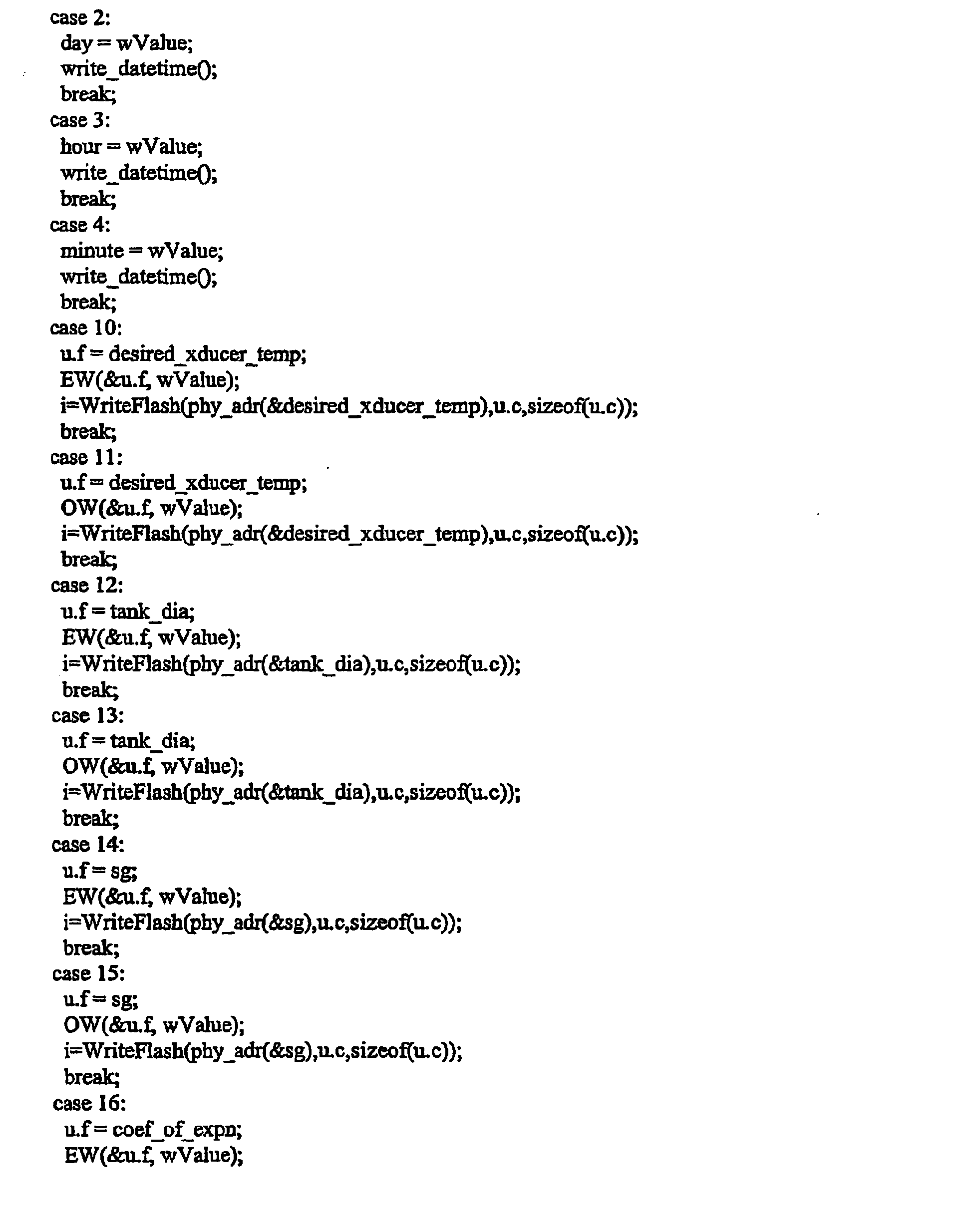
- Annex A is a printout of the computer program source code referred to herein as the RTU program.
- a preferred embodiment of a storage tank leak detection system is generally designated as system 10.
- An embodiment of the present invention is shown to include a vacuum-sealed canister 12, which houses and protects a plurality of mass measurement components and system control components.
- vacuum-sealed canister 12 is made of a substantially non-corrosive metal (aluminum, for example), however, any material that is corrosion resistant and offers sufficient protection to the components enclosed is adequate for use with the present invention.
- Canister 12 is directly immersed in storage tank 60 and rests on storage tank bottom surface 62.
- Canister 12 further contains vacuum seal nozzle 14 and transducer high side aperture 20.
- Vacuum seal nozzle 14 allows communication means to pass from the inside of the canister to the outside of the canister while maintaining the integrity of the vacuum inside the canister.
- Vacuum nozzle 14 further contains barometric pressure measuring means aperture 16 and transducer low side aperture 18.
- canister hose 15 forms a fluid tight seal with vacuum seal nozzle 14. Extending from vacuum seal nozzle 14, canister hose 15 passes through storage tank top surface recess 64 to an area outside of the class I region of storage tank 60 (class I region refers to the National Electric Code designated hazardous areas in which only power wattage levels of less than certain prescribed levels may be introduced).
- Canister hose 15 serves as a conduit for communication means extending though vacuum nozzle 14 and as an atmospheric reference in its service as a barometric pressure measuring means reference hose.
- Canister hose 15 allows transducer low side aperture 18 and barometric pressure measuring means aperture 16 to be directly exposed to atmospheric pressure while maintaining a fluid tight seal with vacuum seal nozzle 14 thereby preserving the integrity of the vacuum of canister 12.
- differential pressure transmitter 22 Contained within vacuum-sealed canister 12 is differential pressure transmitter 22.
- differential pressure transmitter 22 is comprised of a highly precise quartz crystal type pressure transducer 24.
- Transducer 24 contains an oscillating quartz crystal and has a resolution of 1x10⁻⁸, as known in the industry. Such a unit is available from Paroscientific, Inc. as Model No. 6015-G. The ultimate resolution achievable with a transducer is limited by its noise level. System 10 greatly reduces noise thereby increasing the resolution of transmitter 24.
- transmitter 22 has been modified from its original configuration so that it may be directly immersed in storage tank 60. This modification has eliminated dependence on any bubbler unit (thereby eliminating noise associated with such units) as required by other products.
- transducer 24 is held at a constant temperature and secured in vacuum to further reduce noise.
- Quartz crystal type pressure transducer 24 is further comprised of transducer low side 26.
- Transducer low side 26 is a differential reference that receives the barometric pressure value at the liquid surface.
- Transducer low side tube 28 forms an air tight seal at it proximate end with transducer low side 26 and extends though the vacuum of canister 12 where it forms an air tight seal at its distal end at transducer low side aperture 18 of vacuum seal nozzle 14.
- Transducer low side tube 28 allows transducer low side 26 to receive the barometric pressure from the reference point at the liquid surface while allowing canister 12 to remain in vacuum.
- Quartz crystal type pressure transducer 24 is further comprised of transducer high side 30.
- Quartz crystal type pressure transducer high side 30 is a pressure reference point, which measures the sum of the barometric and hydrostatic pressure at tank bottom surface 62.
- Transducer high side 30 contains a protruding transducer high side tube 32.
- transducer high side tube 32 is filled with a pressure-sensing liquid and extends through transducer high side aperture 20 where it is ported to the product contained in tank 60.
- Transducer high side tube 32 is surrounded by tube fitting 34.
- tube fitting 34 slides along high side tube 32 and forms a fluid tight seal at high side aperture 20. Tube fitting 34 allows high side tube 32 to extend through high side aperture 20 while maintaining the integrity of the vacuum of canister 12.
- Transducer 24 subtracts the value received at transducer low side 26 from the value received at transducer high side 30 to arrive at the pressure exerted by the mass of the stored product.
- This data is transmitted along data transfer means 23.
- data transfer means 23 is a standard bus communications cable. However, one could easily envision a data transfer means such as wireless communication that would work equally as well.
- Data transfer means 23 extends from the output of differential pressure transmitter 22 through vacuum seal nozzle 14 and continues, separated from storage tank's 60 contents by canister hose 15, to data logging computer 30.
- Current transmitter 34 serves as a part of a temperature regulation scheme used to keep the contents of canister 12 at a constant temperature during the data gathering process.
- Current transmitter 34 in the preferred embodiment, actuates a resistive heater 36 by a simple on/off control loop.
- Heat sink 38 acting in combination with current transmitter 34 and resistive heater 36 acts to regulate the temperature of canister 12. While the above temperature regulating scheme has been described with reference to one embodiment, one could easily imagine other temperature regulation schemes that would work equally as well.
- Data transfer means 39 extends from the output of current transmitter 34 through vacuum seal nozzle 14 and continues, separated from storage tank's 60 contents by canister hose 15, to data logging computer 30.
- data transfer means 39 is a standard bus communications cable. However, one could easily envision a data transfer means such as wireless communication that would work equally as well.
- temperature of transmitter 22 is maintained, according to the presently preferred mode of the present invention, at a temperature of approximately 1°F above the ambient temperature of the product (oil or gasoline, for example) in tank 60. If, for example, the product is at 50°F, transmitter 22 is maintained at 51°F, if the product is at 90° F, transmitter 22 is maintained at 91 ° F, and so forth.
- Barometric measuring means 40 serves as an independent reference for true atmospheric pressure.
- barometric pressure measuring means 40 may be any standard barometer that sends signals to be processed by data logging computer 30. Barometric measuring means 40 is very useful for increasing the precision of system 10. All transducers decrease in accuracy over time as they lose their calibration with respect to true atmospheric pressure. This is known as zero drift.
- the present invention employs barometric measuring means 40 to serve as an independent measure of true atmospheric pressure thereby allowing for data correction over any extended period of time. As will be discussed in this section, data correction using values taken from barometric pressure measuring means 40 is software based and greatly increases the precision of the current invention.
- Barometric measuring means tube 42 forms an air tight seal at it proximate end with Barometric measuring means 40 and extends though the vacuum of canister 12 where it forms an air tight seal at its distal end at barometric measuring means aperture 16 of vacuum seal nozzle 14.
- Barometric measuring means tube 42 allows barometric measuring means 40 to receive the barometric pressure from the reference point at the surface of liquid within storage tank 60, while allowing the interior of canister 12 (with transmitter 22 installed therein) to remain in vacuum so as to substantially eliminate any environmentally-effected variations in instrument performance).
- Data transfer means 43 extends from the output of barometric pressure measuring means 40 through vacuum seal nozzle 14 and continues, separated from storage tank's 60 contents by canister hose 15, to data logging computer 30.
- data transfer means 43 is a standard bus communications cable. However, one could easily envision a data transfer means such as wireless communication that would work equally as well.
- remote computer 30 is typically housed in a separate enclosure, such as field unit 50.
- data logging computer processes data received from transmitter 22, current transmitter 34, resistive heater 36, heat sink 38, and barometric pressure measuring means 40.
- Data logging computer 30 communicates with remote computer 70 by data transfer means 72.
- the software commences operation with the initialization of data collection at the tank bottom, along with the atmospheric and environmental conditions. Data is automatically collected via computer controlled programming over some length of time, preferably 36 to 60 hours. The length of the test is dependent on tank size and site atmospheric conditions.
- data transfer means 72 is a standard bus communications cable. However, one could easily envision a data transfer means such as wireless communication that would work equally as well.
- remote computer 70 contains software that performs linear regressions of data received from data logging computer 30. This regression detects minuscule changes in the mass of the stored product, thereby indicating the presence of the smallest of leaks. As the compilation of data grows, the more precise the regression becomes.
- the post processing module and software of remote computer 70 is independent of the data-logging computer 30.
- the RTU program is performed by data logging computer 30 and is responsible for obtaining (routine 100) and correcting (routine 200) pressure readings from transmitter 22, controlling the temperature of transmitter 22 (routine 300), calculating adjustments for tank shell expansions (routine 400), obtaining transmitter 22 temperature (routine 500), and data storage.
- the data acquired by the RTU program is stored within data-logging computer 30 in non-volatile memory 31.
- the purpose of the RTU program is to interrogate an intelligent differential pressure transmitter (transmitter 22) via a serial connection.
- the pressure read from transmitter 22 is the difference in pressure read from transducer low side 26 and transducer high side 30. That pressure value is modified by two additional variables in order to improve the accuracy of the reading.
- the program performs correction of barometric pressure; an analog barometer (such as barometric pressure measuring means 40) provides the signal that is sent to correct transmitter pressure for errors due to changes in barometric pressure, as measured at the upper surface of the contents of storage tank 60.
- the program monitors ambient temperature to compensate for changes in the tank diameter which otherwise would skew the data interpretation, intended solely to detect variations of contents of storage tank 60 due to leakage. Any change in tank diameter is accommodated in the calculations of transmitter 22, thus properly attributing substantially all variations in differential pressure (already corrected for variations in atmospheric pressure, as mentioned above) to variations in the content of storage tank 60, such as through leakage.
- Routine 100 obtaining pressure readings from transmitter 22, is performed every one minute as follows: at step 101 a command is sent to transmitter 22 to obtain a new pressure sample, at step 102 a command to wait for the new sample is sent, at step 103 a command to ask for the new sample is sent.
- the data is returned as an ASCII psi number.
- Routine 200 adjusting transducer 24 pressure reading according to barometric measuring means 40, is performed as follows:
- the user enters installation parameters reflecting: (1) a predetermined barometric correction factor which is laboratory-determined for each transmitter 22 to establish, and to later enable calibration of the transmitter 22's Azero point@; (2) the coefficient of expansion for storage tank 60 (a factor readily calculated by persons reasonably skilled in the relevant field, applying common materials engineering principles to standards pertaining to storage tank design and materials); (3) the ambient temperature at the installation site at the time installation (for use in calculating dimensional variations in tank 60 according to the aforementioned coefficient of expansion; and (4) the specific gravity of the product contained in storage tank 60.
- the user will also enter the desired temperature setting for resistive heater 36.
- the number 14.5 is a somewhat arbitrary number which is fairly close to an expected range of actual, measured barometric pressure.
- This factor is subtracted from measured barometric pressure in order to reduce certain calculated figures to a smaller, and more manageable level for later processing (linear regression, etc.) in tracking minute mass differences in storage tank contents.
- this adjusted or derived pressure data is used to calculate the mass of the product in the tank based on the tank's diameter.
- Routine 300 controlling transducer 24 temperature, is performed as follows: at step 301 the digital output to current transmitter 34 is turned on when the temperature read from analog input of heat sink 38 is 1 degree below the temperature set point, at step 302 the digital output to current transmitter 34 is turned off when the temperature is 0.1 degree above the set point.
- Routine 400 adjusting the previously derived content mass for tank shell expansion, is performed as follows: at step 401 the ambient temperature is averaged to obtain a temperature to use in calculating the change in tank diameter, this calculation requires the coefficient of expansion and the tank diameter to be entered by the user either at startup (as mentioned previously) or at any time, the result obtained is used to adjust the total mass in the tank for erroneous, environmentally effected false indications of changes in the content of tank 60, to yield purely leakage related variations (assuming no intension addition or removal of contents by other means).
- Routine 500 obtaining transducer 24 temperature, is performed as follows: at step 501 a command is sent to transmitter 22 to obtain a new temperature, at step 502 a command to wait for the temperature reading is sent, at step 503 a command to ask transmitter 22 for the new reading is sent.
- the RTU program is responsible for data storage.
- the amount of data storage available will determine how many days of data are stored for retrieval.
- One record per minute is stored.
- the organization of the date is by days.
- the record for every minute will include: (1) the tank contents in pounds (as a floating-point number, IEEE 32 bit format), (2) the barometric pressure (as a x100-16 bit integer), (3) the ambient temperate (as x100-16 bit integer).
- Other data such as previous transducer temperatures, tank diameter, and tank coefficient of expansion, may also be stored as current data.
- the second software program of the storage tank leak detection system of the claimed invention is the linear regression program.
- Remote computer 70 performs this program.
- Routine 700 linear regression of received data, is performed as follows: at step 701 the data file created by the RTU program is created and the leak analysis is performed, at step 702 the data sections are selected for the quality of weather during that particular data section- only nighttime data are typically used in order to minimize extraneous noise in the analysis, at step 703 a best linear fit is used for data points in each data section- when the sections of data that represent durations of appropriately low noise level are included in the best fit data regression, the slope of the best fit line indicates the leak rate. Calculation of the linear regression and best fit are straightforward and could be performed by common software such as Microsoft Excel.
- the present device will obviate significant inconvenience and provide substantial utility to those who wish to detect leaks in storage tanks. Specifically, the present device will allow very small leaks to be detected in very large storage tanks in a consistent and cost-effective manner.
Landscapes
- Physics & Mathematics (AREA)
- General Physics & Mathematics (AREA)
- Examining Or Testing Airtightness (AREA)
Abstract
Description
- This is a continuation application with respect to
U.S. Application, Serial No. 10/614,748, filed 07 July 2003 - The present invention is directed towards a method and apparatus for providing a safe, precise, and cost-effective storage tank leak detection system; and more particularly, to a method and apparatus wherein the containment integrity of a storage tank is determined by mass measurements of the stored product. 2. Background Information.
- Storage tanks play a vital role in today's economy. The economy, on a global scale, depends on the proper function of these tanks as they are prevalent in several industries and virtually every geographical region in the world. In light of the vital role these storage tanks play, the integrity of the tanks is placed at a premium. That is, storage tank owners are willing to invest huge sums of money in both the maintenance and inspection of such tanks.
- These tanks come in all shapes and sizes, are found both below and above ground, and are used to store a wide-range of materials. Storage tank capacities range from hundreds to millions of gallons and are used to store a staggering assortment of products; these storage tanks are commonly used to store hazardous material.
- As one could imagine, there is a wide range of problems associated with maintaining storage tank integrity, particularly with above ground storage tanks. Given the enormous dimensions of above ground tanks, the corrosive products contained within the tanks, the incredible mass of the stored product, and the extreme weather conditions the tanks are subjected to; it is plain to see that above ground storage tank leaks are an all-to-common problem. Using the United States Environmental Protection Agency leak detection threshold criteria of .05 gallons per hour in a 10,000-gallon underground tank, that threshold would equate to a 15 gallon per hour detection level in an 80,000 barrel above ground tank. Given the limited number of systems capable of meeting the EPA's underground storage tank leak detection threshold and the added difficulties associated with above ground tanks, the difficulty in protecting against and detecting leaks is easily seen.
- However, the recognized difficulty in preventing storage tank leaks does not mitigate the duties or liabilities imposed on responsible parties. Tremendous environmental and economic consequences and the threat of litigation and clean up costs associated with storage tank leaks force responsible parties to invest large sums of money in the maintenance and inspection of the tanks. Tank inspections are costly with respect to the amount of money spent, the danger presented to the inspectors and the environment, and production downtime. In fact, these inspections often remove a tank from service for more than one month. The threat of liability also forces responsible parties to spend money unnecessarily for the maintenance of these tanks. Moreover, liability does not end with litigation and clean-up costs.
- Currently, responsible parties are, in some countries, being incarcerated as a direct result of storage tanks leaks. These leaks have contaminated surrounding ground water, some of which serves as drinking water for local residents. As such, the facilities associated with such incidents have been shutdown until compliance with emissions regulations can be established beyond reasonable doubt. Such proof, in turn, is dependent on proof of reliable and sufficiently accurate detection systems and methods for proving such compliance. Each day the shuttered facilities remain inoperative adds to an already tremendous amount of money lost.
- Prior to the present invention (to be described in detail hereafter), there are simply no known systems or methods by which the leak detection requirements can be met. Presently available leak detection systems lack detection thresholds low enough to detect leaks down to permissible upper leakage limits for above ground storage tanks.
- Clearly, for the reasons set forth above, there is a dire and immediate need for the ability to determine, with far more precision than presently possible through use of presently available systems and methods, the presence and degree of leakage from above ground storage tanks, at least to the extent of proving compliance with applicable storage tank leakage regulations or statutes.
- Storage tank leak detection systems are known in the art; as disclosed in documents
US4862733 andUS5201212A1 however, these products are fraught with problems. The present systems are imprecise, or provide erroneous data for any or all of reasons including: the consistency of the soil acting as the tank's foundation, the temperature stratification of the in-tank product, extraneous noise sources, thermal expansion of the tank's contents, water table level, previous soil contamination, and/or tank shell dynamics. - Further, some detection devices can only be used when the storage tank is empty, and no known system or method ensures a comprehensive inspection of the tank. The most common form of such a system is Avacuum box testing; @ however, this system is intended only for weld joints and is not usually applied to the entire tank bottom. Magnetic flux floor scanning is also used, but is not effective at examining the area of the floor surface close to the surface walls or where there are physical obstructions. Ultrasonic detection is used, but this is only effective for small areas of the surface. Gas detection is also used, but the types of materials stored in the tank can obstruct this method.
- Other common leak detection systems employ a level sensor. However, even large volume changes produce only small level changes, as the cross-sectional area of the liquid surface in these tanks is very large. This, combined with differential expansion and temperature change of the stored liquid and its vapor, make this type of detection system inconsistent and very nearly worthless.
- Finally, mass measurement detection systems are known in the art. However, the presently available systems and associated methods are not capable of the precision, which is indicated above as crucial at the present time (and which, as described below, is afforded by the systems and methods of the present invention). Present mass measurement leak detection systems in the art are limited by tank shell variations resulting from temperature effects on tank shell plating. As such, known mass measurement detection systems are only sensitive enough to be used in smaller tanks, typically underground storage tanks. However, as will be seen in the specification to follow, the present invention overcomes tank shell variations and other shortcomings of presently known technology in this field through data collection and data correction apparatus, techniques and interpretation.
- In light of the severe consequences of failing to detect significant storage tank leaks, presently not detectable through use of known systems or methods, there is a compelling need for a system and method by which one can detect very small leaks even in very large tanks, ideally in a safe and cost effective manner.
- It would well serve those who are responsible for maintaining storage tank integrity to provide a safe, precise, and cost-effective detection system that does not depend on independent variables such as fluid temperature, fluid stratification, or tank stabilization, and may be used in an efficient manner thereby preserving industrial and environmental resources.
- In view of the foregoing, it is an object of the present invention to provide a storage tank leak detection apparatus with a very low detection threshold that may be used in an efficient manner thereby preserving industrial and environmental resources.
- It is another object of the present invention to provide an apparatus for safe storage tank leak detection
- It is another object of the present invention to provide an apparatus for precise storage tank leak detection
- It is another object of the present invention to provide an apparatus for cost-effective storage tank leak detection
- It is another object of the present invention to provide an apparatus for non-intrusive storage tank leak detection
- It is another object of the present invention to provide an apparatus for storage tank leak detection where the contents of the storage tank do not have to be removed
- It is another object of the present invention to provide an apparatus for storage tank leak detection where no chemical additives are involved
- It is another object of the present invention to provide an apparatus for immediate storage tank leak detection
- It is another object of the present invention to provide an apparatus for conclusive storage tank leak detection
- It is another object of the present invention to provide an apparatus for quantitative storage tank leak detection
- It is another object of the present invention to provide an apparatus for storage tank leak detection that does not depend on fluid temperature changes
- It is another object of the present invention to provide an apparatus for storage tank leak detection that does not depend on fluid stratification
- It is another object of the present invention to provide an apparatus for storage tank leak detection that does not require tank stabilization time
- It is another object of the present invention to provide an apparatus for storage tank leak detection that requires only minimal tank preparation
- It is another object of the present invention to provide an apparatus for storage tank leak detection that has been evaluated by an EPA-recognized, independent third party laboratory
- It is another object of the present invention to provide a method with a very low detection threshold that may be used in an efficient manner thereby preserving industrial and environmental resources.
- It is another object of the present invention to provide a method for safe storage tank leak detection
- It is another object of the present invention to provide a method for precise storage tank leak detection
- It is another object of the present invention to provide a method for cost-effective storage tank leak detection
- It is another object of the present invention to provide a method for non-intrusive storage tank leak detection
- It is another object of the present invention to provide an apparatus for storage tank leak detection where the contents of the storage tank do not have to be removed
- It is another object of the present invention to provide an apparatus for storage tank leak detection where no chemical additives are involved
- It is another object of the present invention to provide a method for immediate storage tank leak detection
- It is another object of the present invention to provide a method for conclusive storage tank leak detection
- It is another object of the present invention to provide a method for quantitative storage tank leak detection
- It is another object of the present invention to provide a method for storage tank leak detection that does not depend on fluid temperature changes
- It is another object of the present invention to provide a method for storage tank leak detection that does not depend on fluid stratification
- It is another object of the present invention to provide a method for storage tank leak detection that does not require tank stabilization time
- It is another object of the present invention to provide a method for storage tank leak detection that requires only minimal tank preparation
- It is yet another object of the present invention to provide a method for storage tank leak detection that has been evaluated by an EPA-recognized, independent third party laboratory.
- The present invention provides a safe, extremely precise, and cost-effective solution to the problems mentioned above. Test results associated with the present invention provide an accurate determination of containment integrity, and in the event of leakage, a precise volumetric leak rate. The present invention is not restricted by fluid type, fluid temperature, fluid level, or tank size.
- Distinguished from products know in the art, the present invention provides an intrinsically safe detection system. The leak detection system of the present invention uses a sufficiently low wattage (as established in the National Electric Code) so that the components of the system may be placed within the class I area of the tank. In fact, the present invention provides for leak detection system components to be placed within the storage tank. As will be described in the specification to follow, placement of leak detection components in the tank used in combination with system control techniques and data correction software, provide for precision not possible with products known in the art.
- Further, no physical inspection of the tanks is required for practice of the present system. As such, there is no need to drain, clean, or enter the tank. With no need for physical inspection, neither inspectors nor the environment are exposed to the contents of the tank. With no need to drain the storage tank, practice of the present invention does not produce hazardous by-products associated with the draining/cleaning process, and danger from transport and storage of the drained product is avoided. Finally, the systems and methods of the present invention do not require chemical additives to be mixed with the tank contents. As such, incidental spills and leaks are avoided altogether.
- Practice of the present invention is cost effective. Tank structure or the foundation and surrounding soil are not disturbed, as such; set-up time and capital investment costs are minimized. The present invention is non-intrusive and does not require manual inspection of the tank. Therefore, operation of the tank is not hindered, so there is no production downtime. There is no cost related to the handling, transport, disposal, or storage of removed hazardous material. Finally, testing can be accomplished simultaneously to further reduce the total time involved and rapidly identify problem areas.
- The determinative feature of mass measurement leak detection systems is the sensitivity of the apparatus. That is, the lower the leak detection threshold level of a device, the more effective it will be at detecting leaks. The present invention, by employing a combination of techniques and components not known in the art, provides a leak detection threshold that is much lower than any known device. Most importantly, the system of the present invention provides for placing mass measuring components within the actual storage tank, thereby eliminating extraneous noise associated with bubbler units required by other products in the art. The system secures the mass measuring components within a vacuum and holds the mass measurement component's temperature constant during the entire measurement process. Further, the system corrects errors in the data attributed to storage tank shell dynamics and inherent imprecision in the mass measurement devices. This data correction process will be discussed in detail in the specification to follow.
- As mentioned, tank shell variations limit the effectiveness of presently known mass measurement detection systems. The systems and methods of the present invention overcome tank shell variations through data collection and data correction techniques. First, data is collected through use of a quartz crystal type pressure transducer (the specifications and use of this transducer will be explained in more detail in the Detailed Description of the Preferred Embodiment). An intrinsically safe remote terminal unit, connected to the pressure transducer, records pressure data over a period of time (preferably one to five nights). The atmospheric temperature and barometric pressure are recorded and precisely analyzed to calculate any changes in the mass of the fluid within the tank. This data is regressed to give a line slope that is converted to a leak rate, usually in gallons per hour.
- Data generated by the transducer is collected on a 24-hour basis. Only data containing a sufficiently low amount of extraneous noise is analyzed. Such data is usually obtained at nighttime and during fair weather conditions. Also, data correction software accounts for the coefficient of expansion for any given storage tank. This correction eliminates the effect of the sun's radiant energy on the area of the surface tank, which may adversely affect the mass measurement of the stored product. The nighttime data is corrected for atmospheric conditions and variations in the tank shell. These measurements and corrections allow the system to repeatedly achieve the stated accuracy in real world conditions on a routine basis.
- For even greater precision, the leak detection system of the present invention provides for an independent barometric measuring means to constantly record the barometric pressure during the data collection process. This independent barometric pressure measuring means used in combination with data correction software, corrects any zero drift associated with the individual pressure transducer. That is, this system corrects for the inherent error present in any transducer when that transducer deviates from its initial calibration.
- Practice of the apparatus involves securing a combination of precise mass measurement components, including a highly precise quartz crystal type pressure transducer, in a vacuum-sealed canister. This canister is then lowered to the bottom surface of a storage tank. A differential reference is placed just above a liquid surface. The pressure, measured at the tank floor ("tank bottom pressure") and atmospheric pressure measured just above the liquid surface, is recorded by the above-referenced micro sensitive differential pressure transducer, recorded on a real time basis and post processed using a data analysis routine to accurately calculate any changes in the mass of fluid contained within the tank to determine if there is a loss. The present system, using the specified transducer, and when used in the manner and with the data interpretation described herein, is capable of detecting above ground storage tank leaks at a threshold of less than .9 gallons per hour with a probability of detection of 95 % in a 100,000 barrel tank B far more accurate than possible with any presently available quantitative leak detection system. This, quantitatively, amounts to detecting pressure differentials equivalent to less than 1/10,000th inch of water column pressure, a tolerance level necessary to achieve such detection thresholds.
- The method and apparatus of the present invention provides a safe and effective way to detect very small leaks in very large tanks. Particularly, the present invention provides a tremendous improvement in accuracy and leak detection threshold, allowing its users to achieve greater results than presently thought possible.
- Thus, in satisfaction of the above objects, an embodiment of the present invention provides systems and methods for solving each of the stated problems with presently available storage tank leak detection systems.
- Annex A is a printout of the computer program source code referred to herein as the RTU program.
-
Fig. 1 is a block diagram depicting the general layout of the present leak detection system. -
Fig. 2 is an elevational, sagital cross sectional view of the canister ("protective enclosure means") of the leak detection system. - In the drawings and the description that follows, referring to
figure 1 , a preferred embodiment of a storage tank leak detection system according to the present invention is generally designated as system 10. An embodiment of the present invention is shown to include a vacuum-sealedcanister 12, which houses and protects a plurality of mass measurement components and system control components. In the preferred embodiment, vacuum-sealedcanister 12 is made of a substantially non-corrosive metal (aluminum, for example), however, any material that is corrosion resistant and offers sufficient protection to the components enclosed is adequate for use with the present invention.Canister 12 is directly immersed instorage tank 60 and rests on storagetank bottom surface 62.Canister 12 further containsvacuum seal nozzle 14 and transducerhigh side aperture 20.Vacuum seal nozzle 14 allows communication means to pass from the inside of the canister to the outside of the canister while maintaining the integrity of the vacuum inside the canister.Vacuum nozzle 14 further contains barometric pressure measuring meansaperture 16 and transducer low side aperture 18. - At its proximate
end canister hose 15 forms a fluid tight seal withvacuum seal nozzle 14. Extending fromvacuum seal nozzle 14,canister hose 15 passes through storage tank top surface recess 64 to an area outside of the class I region of storage tank 60 (class I region refers to the National Electric Code designated hazardous areas in which only power wattage levels of less than certain prescribed levels may be introduced).Canister hose 15 serves as a conduit for communication means extending thoughvacuum nozzle 14 and as an atmospheric reference in its service as a barometric pressure measuring means reference hose.Canister hose 15 allows transducer low side aperture 18 and barometric pressure measuring meansaperture 16 to be directly exposed to atmospheric pressure while maintaining a fluid tight seal withvacuum seal nozzle 14 thereby preserving the integrity of the vacuum ofcanister 12. - Contained within vacuum-sealed
canister 12 isdifferential pressure transmitter 22. In the preferred embodiment,differential pressure transmitter 22 is comprised of a highly precise quartz crystaltype pressure transducer 24.Transducer 24 contains an oscillating quartz crystal and has a resolution of 1x10⁻⁸, as known in the industry. Such a unit is available from Paroscientific, Inc. as Model No. 6015-G. The ultimate resolution achievable with a transducer is limited by its noise level. System 10 greatly reduces noise thereby increasing the resolution oftransmitter 24. In system 10,transmitter 22 has been modified from its original configuration so that it may be directly immersed instorage tank 60. This modification has eliminated dependence on any bubbler unit (thereby eliminating noise associated with such units) as required by other products. As will be further described in this section,transducer 24 is held at a constant temperature and secured in vacuum to further reduce noise. - Quartz crystal
type pressure transducer 24 is further comprised of transducerlow side 26. Transducerlow side 26 is a differential reference that receives the barometric pressure value at the liquid surface. Transducerlow side tube 28 forms an air tight seal at it proximate end with transducerlow side 26 and extends though the vacuum ofcanister 12 where it forms an air tight seal at its distal end at transducer low side aperture 18 ofvacuum seal nozzle 14. Transducerlow side tube 28 allows transducerlow side 26 to receive the barometric pressure from the reference point at the liquid surface while allowingcanister 12 to remain in vacuum. - Quartz crystal
type pressure transducer 24 is further comprised of transducerhigh side 30. Quartz crystal type pressure transducerhigh side 30 is a pressure reference point, which measures the sum of the barometric and hydrostatic pressure attank bottom surface 62. Transducerhigh side 30 contains a protruding transducer high side tube 32. In the preferred embodiment, transducer high side tube 32 is filled with a pressure-sensing liquid and extends through transducerhigh side aperture 20 where it is ported to the product contained intank 60. Transducer high side tube 32 is surrounded by tube fitting 34. In the preferred embodiment, tube fitting 34 slides along high side tube 32 and forms a fluid tight seal athigh side aperture 20. Tube fitting 34 allows high side tube 32 to extend throughhigh side aperture 20 while maintaining the integrity of the vacuum ofcanister 12. -
Transducer 24 subtracts the value received at transducerlow side 26 from the value received at transducerhigh side 30 to arrive at the pressure exerted by the mass of the stored product.Transmitter 22, communicating digitally, then sends this processed information to data-loggingcomputer 30. This data is transmitted along data transfer means 23. In the preferred embodiment, data transfer means 23 is a standard bus communications cable. However, one could easily envision a data transfer means such as wireless communication that would work equally as well. Data transfer means 23 extends from the output ofdifferential pressure transmitter 22 throughvacuum seal nozzle 14 and continues, separated from storage tank's 60 contents bycanister hose 15, todata logging computer 30. - Also contained within
canister 12 iscurrent transmitter 34.Current transmitter 34 serves as a part of a temperature regulation scheme used to keep the contents ofcanister 12 at a constant temperature during the data gathering process.Current transmitter 34, in the preferred embodiment, actuates aresistive heater 36 by a simple on/off control loop.Heat sink 38, acting in combination withcurrent transmitter 34 andresistive heater 36 acts to regulate the temperature ofcanister 12. While the above temperature regulating scheme has been described with reference to one embodiment, one could easily imagine other temperature regulation schemes that would work equally as well. Data transfer means 39 extends from the output ofcurrent transmitter 34 throughvacuum seal nozzle 14 and continues, separated from storage tank's 60 contents bycanister hose 15, todata logging computer 30. In the preferred embodiment, data transfer means 39 is a standard bus communications cable. However, one could easily envision a data transfer means such as wireless communication that would work equally as well. - The use of this temperature regulation scheme to hold
transmitter 22 at a constant temperature further increases the precision of the current apparatus. The absolute temperature at whichtransmitter 22 is maintained is not critical, rather constancy of temperature affects the integrity of the subject measurements. As a matter of practicality and economy, temperature oftransmitter 22 is maintained, according to the presently preferred mode of the present invention, at a temperature of approximately 1°F above the ambient temperature of the product (oil or gasoline, for example) intank 60. If, for example, the product is at 50°F,transmitter 22 is maintained at 51°F, if the product is at 90° F,transmitter 22 is maintained at 91 ° F, and so forth. - Also contained within
canister 12 is barometric pressure measuring means 40. Barometric measuring means 40 serves as an independent reference for true atmospheric pressure. In the preferred embodiment, barometric pressure measuring means 40 may be any standard barometer that sends signals to be processed bydata logging computer 30. Barometric measuring means 40 is very useful for increasing the precision of system 10. All transducers decrease in accuracy over time as they lose their calibration with respect to true atmospheric pressure. This is known as zero drift. However, the present invention employs barometric measuring means 40 to serve as an independent measure of true atmospheric pressure thereby allowing for data correction over any extended period of time. As will be discussed in this section, data correction using values taken from barometric pressure measuring means 40 is software based and greatly increases the precision of the current invention. - Barometric measuring means
tube 42 forms an air tight seal at it proximate end with Barometric measuring means 40 and extends though the vacuum ofcanister 12 where it forms an air tight seal at its distal end at barometric measuring meansaperture 16 ofvacuum seal nozzle 14. Barometric measuring meanstube 42 allows barometric measuring means 40 to receive the barometric pressure from the reference point at the surface of liquid withinstorage tank 60, while allowing the interior of canister 12 (withtransmitter 22 installed therein) to remain in vacuum so as to substantially eliminate any environmentally-effected variations in instrument performance). Data transfer means 43 extends from the output of barometric pressure measuring means 40 throughvacuum seal nozzle 14 and continues, separated from storage tank's 60 contents bycanister hose 15, todata logging computer 30. In the preferred embodiment, data transfer means 43 is a standard bus communications cable. However, one could easily envision a data transfer means such as wireless communication that would work equally as well. - Although not necessary,
remote computer 30 is typically housed in a separate enclosure, such asfield unit 50. In accordance with the described routines to follow and the exemplary computer code depicted in Annex A attached hereto and incorporated herein by reference, data logging computer processes data received fromtransmitter 22,current transmitter 34,resistive heater 36,heat sink 38, and barometric pressure measuring means 40.Data logging computer 30 communicates withremote computer 70 by data transfer means 72. - The software commences operation with the initialization of data collection at the tank bottom, along with the atmospheric and environmental conditions. Data is automatically collected via computer controlled programming over some length of time, preferably 36 to 60 hours. The length of the test is dependent on tank size and site atmospheric conditions. In the preferred embodiment, data transfer means 72 is a standard bus communications cable. However, one could easily envision a data transfer means such as wireless communication that would work equally as well.
- As will be discussed and illustrated hereafter,
remote computer 70 contains software that performs linear regressions of data received fromdata logging computer 30. This regression detects minuscule changes in the mass of the stored product, thereby indicating the presence of the smallest of leaks. As the compilation of data grows, the more precise the regression becomes. The post processing module and software ofremote computer 70 is independent of the data-loggingcomputer 30. - There are two software programs or modules involved with the storage tank leak detection system of the present invention: The RTU program and the linear regression program.
- The RTU program is performed by
data logging computer 30 and is responsible for obtaining (routine 100) and correcting (routine 200) pressure readings fromtransmitter 22, controlling the temperature of transmitter 22 (routine 300), calculating adjustments for tank shell expansions (routine 400), obtainingtransmitter 22 temperature (routine 500), and data storage. The data acquired by the RTU program is stored within data-loggingcomputer 30 in non-volatile memory 31. - The purpose of the RTU program is to interrogate an intelligent differential pressure transmitter (transmitter 22) via a serial connection. The pressure read from
transmitter 22 is the difference in pressure read from transducerlow side 26 and transducerhigh side 30. That pressure value is modified by two additional variables in order to improve the accuracy of the reading. The program performs correction of barometric pressure; an analog barometer (such as barometric pressure measuring means 40) provides the signal that is sent to correct transmitter pressure for errors due to changes in barometric pressure, as measured at the upper surface of the contents ofstorage tank 60. Also, the program monitors ambient temperature to compensate for changes in the tank diameter which otherwise would skew the data interpretation, intended solely to detect variations of contents ofstorage tank 60 due to leakage. Any change in tank diameter is accommodated in the calculations oftransmitter 22, thus properly attributing substantially all variations in differential pressure (already corrected for variations in atmospheric pressure, as mentioned above) to variations in the content ofstorage tank 60, such as through leakage. - Routine 100, obtaining pressure readings from
transmitter 22, is performed every one minute as follows: at step 101 a command is sent totransmitter 22 to obtain a new pressure sample, at step 102 a command to wait for the new sample is sent, at step 103 a command to ask for the new sample is sent. The data is returned as an ASCII psi number. - Routine 200, adjusting
transducer 24 pressure reading according to barometric measuring means 40, is performed as follows: At step 201 the user enters installation parameters reflecting: (1) a predetermined barometric correction factor which is laboratory-determined for eachtransmitter 22 to establish, and to later enable calibration of thetransmitter 22's Azero point@; (2) the coefficient of expansion for storage tank 60 (a factor readily calculated by persons reasonably skilled in the relevant field, applying common materials engineering principles to standards pertaining to storage tank design and materials); (3) the ambient temperature at the installation site at the time installation (for use in calculating dimensional variations intank 60 according to the aforementioned coefficient of expansion; and (4) the specific gravity of the product contained instorage tank 60. The user will also enter the desired temperature setting forresistive heater 36. - At step 202 the following calculations are undertaken:


where (for the present discussion, although not precisely reflected in the same terms in the appended source code) Hadj = adjusted or derived head pressure; H = head pressure in water feet (Hpsi x 2.037); Hpsi = head pressure in pounds per square inch (measured athigh side 30 of transmitter 22); B = barometer reading in pounds per square inch; sg = specific gravity of the content oftank 60; and Bcf = the barometric correction factor. The number 14.5 is a somewhat arbitrary number which is fairly close to an expected range of actual, measured barometric pressure. This factor is subtracted from measured barometric pressure in order to reduce certain calculated figures to a smaller, and more manageable level for later processing (linear regression, etc.) in tracking minute mass differences in storage tank contents. At step 203 this adjusted or derived pressure data is used to calculate the mass of the product in the tank based on the tank's diameter. - Routine 300, controlling
transducer 24 temperature, is performed as follows: at step 301 the digital output tocurrent transmitter 34 is turned on when the temperature read from analog input ofheat sink 38 is 1 degree below the temperature set point, at step 302 the digital output tocurrent transmitter 34 is turned off when the temperature is 0.1 degree above the set point. - Routine 400, adjusting the previously derived content mass for tank shell expansion, is performed as follows: at step 401 the ambient temperature is averaged to obtain a temperature to use in calculating the change in tank diameter, this calculation requires the coefficient of expansion and the tank diameter to be entered by the user either at startup (as mentioned previously) or at any time, the result obtained is used to adjust the total mass in the tank for erroneous, environmentally effected false indications of changes in the content of
tank 60, to yield purely leakage related variations (assuming no intension addition or removal of contents by other means). - Routine 500, obtaining
transducer 24 temperature, is performed as follows: at step 501 a command is sent totransmitter 22 to obtain a new temperature, at step 502 a command to wait for the temperature reading is sent, at step 503 a command to asktransmitter 22 for the new reading is sent. - Finally, the RTU program is responsible for data storage. The amount of data storage available will determine how many days of data are stored for retrieval. One record per minute is stored. The organization of the date is by days. The record for every minute will include: (1) the tank contents in pounds (as a floating-point number, IEEE 32 bit format), (2) the barometric pressure (as a x100-16 bit integer), (3) the ambient temperate (as x100-16 bit integer). Other data, such as previous transducer temperatures, tank diameter, and tank coefficient of expansion, may also be stored as current data.
- The second software program of the storage tank leak detection system of the claimed invention is the linear regression program.
Remote computer 70 performs this program. Routine 700, linear regression of received data, is performed as follows: at step 701 the data file created by the RTU program is created and the leak analysis is performed, at step 702 the data sections are selected for the quality of weather during that particular data section- only nighttime data are typically used in order to minimize extraneous noise in the analysis, at step 703 a best linear fit is used for data points in each data section- when the sections of data that represent durations of appropriately low noise level are included in the best fit data regression, the slope of the best fit line indicates the leak rate. Calculation of the linear regression and best fit are straightforward and could be performed by common software such as Microsoft Excel. - It is believed that, while safe and efficient, the present device will obviate significant inconvenience and provide substantial utility to those who wish to detect leaks in storage tanks. Specifically, the present device will allow very small leaks to be detected in very large storage tanks in a consistent and cost-effective manner.
- Although the invention has been described with reference to specific embodiments, these are not meant to be construed in a limited sense. Various modifications of the disclosed embodiments, as well as alternative embodiments of the invention that fall within the scope of the invention will become apparent to person skilled in the art upon the reference to the claims.
-



Claims (7)
- An apparatus for detecting leaks in a liquid storage tank comprising:differential pressure sensor means having a low pressure measurement component and a high pressure measurement component;protective enclosure means for protecting said differential pressure sensor means from materials and conditions when immersed in liquid contents of said storage tank;said high pressure measurement component being configured for measuring tank bottom pressure within a liquid in which said enclosure means is immersed;said low pressure measurement component being configured for receiving data indicative of atmospheric pressure substantially at the surface of said liquid;barometric pressure measuring means configured for measuring atmospheric pressure substantially at the surface of said liquid when said protective enclosure means is immersed therein;barometric pressure and differential pressure calculation means configured for receiving first and second data reflecting, respectively, said tank bottom pressure and said barometric pressure substantially at said surface of said liquid, and for adjusting said first data to substantially eliminate variations upon said measurements of said tank bottom pressure caused solely from atmospheric pressure variations to yield an atmospheric pressure adjusted tank bottom pressure;ambient temperature measurement means for measuring ambient temperature near said storage tank;tank dynamic and barometric pressure adjusted tank bottom pressure calculation means configured for receiving third data indicative of said atmospheric pressure adjusted tank bottom pressure, for receiving fourth data indicative of ambient temperature measurements by said ambient temperature measurement means, for receiving fifth data indicative of expansion characteristics of said storage tank, and for adjusting said third data with reference to said fourth and fifth data to substantially eliminate variations upon measurements and calculations of said barometric pressure adjusted tank bottom pressure, caused solely by dimensional changes in said storage tank resulting from atmospheric temperature variations, to yield a tank dynamic adjusted tank bottom pressure;tank content mass calculation means for calculating mass contents of said storage tank substantially based on said tank dynamic adjusted tank bottom pressure and user input data reflecting physical characteristics of said contents of said storage tank.
- Apparatus according to Claim 1, wherein said protective enclosure means is configured for maintaining at least some components of said apparatus within said protective enclosure means, including said differential pressure sensor, but excepting said low pressure measurement component and said high pressure measurement component, in a substantial vacuum.
- Apparatus according to Claim 1 or 2, further comprising protective enclosure temperature management means configured for maintaining the temperature of said protective enclosure substantially at a user-specified temperature.
- Apparatus according to Claim 1, 2 or 3, wherein the barometric pressure sensing means comprisefirst barometric pressure measuring means configured for measuring atmospheric pressure substantially at the surface of said liquid when said protective enclosure means is immersed therein and for communicating such measurement to said low pressure measurement component of said differential pressure sensor; andsecond barometric pressure measuring means configured for measuring atmospheric pressure substantially at the surface of said liquid when said protective enclosure means is immersed therein;and wherein said barometric pressure and differential pressure calculation means is configured for receiving first and second data reflecting, respectively, said tank bottom pressure and said barometric pressure as measured by said first barometric pressure measuring means and for calculating pressure attributable to liquid content of said storage tank, and receiving data from said second barometric measuring means and, based thereon, adjusting said pressure attributable to said contents of said storage tank to substantially eliminate variations upon said measurements thereof caused solely from atmospheric pressure variations to yield an atmospheric pressure adjusted tank bottom pressure.
- Apparatus according to Claim 4, wherein said protective enclosure means is configured for maintaining at least some components of said apparatus therein, including said differential pressure sensor, but excepting said low pressure measurement component and said high pressure measurement component, substantially in a vacuum.
- A method for detecting leaks in a storage tank; comprising the steps of:selecting apparatus according to any preceding claim,selecting data storage means for collecting a plurality of mass content data as generated by said tank content mass calculation means over a plurality of points in time;selecting computing means configured for generating a human-perceptible indication of changes in said mass content data between a plurality of said points in time;placing said protective enclosure means substantially at a bottom interior surface of said storage tank;actuating said apparatus; andobserving data indicative of changes in said mass content data attributable to leakage of said storage tank to detect of such leakage.
- A method according to Claim 6, further comprising the steps of:securing all input and outflow orifices of said storage tank before said actuation of said apparatus; andsubstantially selectively processing said mass content data which were generated approximately between sunset and sunrise at an installation site of said system.
Applications Claiming Priority (2)
| Application Number | Priority Date | Filing Date | Title |
|---|---|---|---|
| US10/614,748 US6854320B2 (en) | 2003-07-07 | 2003-07-07 | Method and apparatus for storage tank leak detection |
| PCT/US2004/021704 WO2005008206A2 (en) | 2003-07-07 | 2004-07-07 | Method and apparatus for storage tank leak detection |
Publications (3)
| Publication Number | Publication Date |
|---|---|
| EP1651939A2 EP1651939A2 (en) | 2006-05-03 |
| EP1651939A4 EP1651939A4 (en) | 2007-08-08 |
| EP1651939B1 true EP1651939B1 (en) | 2011-05-11 |
Family
ID=33564423
Family Applications (1)
| Application Number | Title | Priority Date | Filing Date |
|---|---|---|---|
| EP04777658A Expired - Lifetime EP1651939B1 (en) | 2003-07-07 | 2004-07-07 | Method and apparatus for storage tank leak detection |
Country Status (5)
| Country | Link |
|---|---|
| US (1) | US6854320B2 (en) |
| EP (1) | EP1651939B1 (en) |
| AT (1) | ATE509262T1 (en) |
| ES (1) | ES2368121T3 (en) |
| WO (1) | WO2005008206A2 (en) |
Families Citing this family (18)
| Publication number | Priority date | Publication date | Assignee | Title |
|---|---|---|---|---|
| US7076398B2 (en) * | 2003-03-12 | 2006-07-11 | Ramvac Dental Products, Inc. | Method for determining vacuum producer system parameters and performance specifications |
| US7000467B2 (en) * | 2003-12-16 | 2006-02-21 | International Business Machines Corporation | Method, system and program product for monitoring rate of volume change of coolant within a cooling system |
| US7739901B2 (en) * | 2004-07-07 | 2010-06-22 | Mass Technology Corporation | System and method for detecting and quantifying changes in the mass content of liquid storage containers |
| US7712352B2 (en) * | 2004-07-07 | 2010-05-11 | Mass Technology Corporation | Method and apparatus for storage tank leak detection |
| US7592916B2 (en) * | 2005-11-16 | 2009-09-22 | Blue Clover Design, Llc | Smart shipping and storage container |
| EP2089703A1 (en) * | 2006-12-01 | 2009-08-19 | Mass Technology Corporation | Detecting and quantifying changes in the mass content of liquid storage containers |
| WO2008085515A1 (en) * | 2007-01-04 | 2008-07-17 | Mass Technology Corporation | Method and apparatus for storage tank leak detection |
| US7929144B1 (en) | 2008-12-16 | 2011-04-19 | The United States Of America As Represented By The Administrator Of The National Aeronautics And Space Administration | Optical system and method for gas detection and monitoring |
| US8468876B2 (en) * | 2009-02-23 | 2013-06-25 | Mass Technology Corporation | Method and apparatus for leak detection in horizontal cylindrical storage tanks |
| US9163153B2 (en) | 2013-03-15 | 2015-10-20 | Sanford, L.P. | Metallic ink composition and writing instrument containing same |
| CN103267618B (en) * | 2013-05-21 | 2015-08-19 | 中国人民解放军总参谋部工程兵第四设计研究院 | Protection airtight unit airtight performance proving installation and method of testing thereof |
| GB2533936B (en) | 2015-01-07 | 2017-10-25 | Homeserve Plc | Flow detection device |
| GB201501935D0 (en) | 2015-02-05 | 2015-03-25 | Tooms Moore Consulting Ltd And Trow Consulting Ltd | Water flow analysis |
| CN113358162B (en) * | 2020-03-05 | 2025-01-17 | 威光自动化科技股份有限公司 | Gas leakage sensing method |
| CN112092627B (en) * | 2020-08-14 | 2021-12-31 | 东风柳州汽车有限公司 | Automobile-used hydrogen leakage detection system |
| CN113188597A (en) * | 2021-04-29 | 2021-07-30 | 开封迪尔空分实业有限公司 | Safety protection system for air separation |
| CN118010192B (en) * | 2024-04-09 | 2024-06-18 | 中国航发四川燃气涡轮研究院 | A method for obtaining the temperature of a rotating disk cavity based on crystal temperature measurement |
| CN119935341B (en) * | 2025-01-13 | 2025-11-07 | 光子洲际科技有限公司 | A passive three-dimensional temperature measurement method, system and storage medium for petrochemical industry |
Family Cites Families (2)
| Publication number | Priority date | Publication date | Assignee | Title |
|---|---|---|---|---|
| US4862733A (en) * | 1987-01-16 | 1989-09-05 | Hyfantis Jr George J | Method and apparatus for detecting leaks in a liquid-containing tank |
| US5201212A (en) * | 1991-02-13 | 1993-04-13 | Tanknology Corporation International | Line leak detector and method |
-
2003
- 2003-07-07 US US10/614,748 patent/US6854320B2/en not_active Expired - Lifetime
-
2004
- 2004-07-07 ES ES04777658T patent/ES2368121T3/en not_active Expired - Lifetime
- 2004-07-07 AT AT04777658T patent/ATE509262T1/en not_active IP Right Cessation
- 2004-07-07 WO PCT/US2004/021704 patent/WO2005008206A2/en not_active Ceased
- 2004-07-07 EP EP04777658A patent/EP1651939B1/en not_active Expired - Lifetime
Also Published As
| Publication number | Publication date |
|---|---|
| US20050005683A1 (en) | 2005-01-13 |
| ES2368121T3 (en) | 2011-11-14 |
| EP1651939A2 (en) | 2006-05-03 |
| ATE509262T1 (en) | 2011-05-15 |
| EP1651939A4 (en) | 2007-08-08 |
| US6854320B2 (en) | 2005-02-15 |
| WO2005008206A3 (en) | 2005-03-31 |
| WO2005008206A2 (en) | 2005-01-27 |
Similar Documents
| Publication | Publication Date | Title |
|---|---|---|
| US6854320B2 (en) | Method and apparatus for storage tank leak detection | |
| US8468876B2 (en) | Method and apparatus for leak detection in horizontal cylindrical storage tanks | |
| US20100256930A1 (en) | System and method for detecting and quantifying changes in the mass content of liquid storage containers | |
| US4827762A (en) | System and method for automatically monitoring liquid volume changes in storage tanks | |
| US5375455A (en) | Methods for measuring flow rates to detect leaks | |
| US4672842A (en) | System and method for automatically monitoring liquid volume changes in storage tanks | |
| US5078006A (en) | Methods for detection of leaks in pressurized pipeline systems | |
| US5090234A (en) | Positive displacement pump apparatus and methods for detection of leaks in pressurized pipeline systems | |
| US6687643B1 (en) | In-situ sensor system and method for data acquisition in liquids | |
| US7712352B2 (en) | Method and apparatus for storage tank leak detection | |
| CA2575772C (en) | Method and apparatus for storage tank leak detection | |
| WO2008085515A1 (en) | Method and apparatus for storage tank leak detection | |
| EP2089703A1 (en) | Detecting and quantifying changes in the mass content of liquid storage containers | |
| AU2001290187B2 (en) | Method and apparatus for determining the volume of liquid in a reservoir | |
| Dalman et al. | A wet-stock management and leak detection system for fuel tanks | |
| Rentsch et al. | Measurement of Ekofisk subsidence | |
| CA1286523C (en) | Apparatus and method for determining rate of leakage of liquid from and into tanks | |
| Maresca Jr et al. | Evaluation of volumetric leak detection methods used in underground storage tanks | |
| AU2001290187A1 (en) | Method and apparatus for determining the volume of liquid in a reservoir | |
| Douglas et al. | Leak testing plan for the Oak Ridge National Laboratory liquid low-level waste systems (active tanks): Revision 2. Volume 1: Regulatory background and plan approach; Volume 2: Methods, protocols, and schedules; Volume 3: Evaluation of the ORNL/LT-823DP differential pressure leak detection method; Appendix to Revision 2: DOE/EPA/TDEC correspondence | |
| Bingham et al. | PRELIMINARY RESULTS AND TEST EXPERIENCE OF THE CAROLINAS VIRGINIA TUBE REACTOR CONTAINMENT LEAKAGE RATE TESTS. | |
| Major et al. | Red hill fuel tank leak detection | |
| Environmental et al. | Selection of liquid-level monitoring method for the Oak Ridge National Laboratory inactive liquid low-level waste tanks, remedial investigation/feasibility study | |
| Mandrup-Jensen et al. | n Experience with comparative testing and calibration FORC: E of Coriolis and turbine meter off-shore and in the laboratory | |
| Hunt et al. | Parameters affecting level measurement interpretation of nuclear fuel solutions |
Legal Events
| Date | Code | Title | Description |
|---|---|---|---|
| PUAI | Public reference made under article 153(3) epc to a published international application that has entered the european phase |
Free format text: ORIGINAL CODE: 0009012 |
|
| 17P | Request for examination filed |
Effective date: 20060203 |
|
| AK | Designated contracting states |
Kind code of ref document: A2 Designated state(s): AT BE BG CH CY CZ DE DK EE ES FI FR GB GR HU IE IT LI LU MC NL PL PT RO SE SI SK TR |
|
| DAX | Request for extension of the european patent (deleted) | ||
| A4 | Supplementary search report drawn up and despatched |
Effective date: 20070709 |
|
| RIC1 | Information provided on ipc code assigned before grant |
Ipc: G01M 3/32 20060101ALI20070703BHEP Ipc: G01M 3/02 20060101AFI20050408BHEP Ipc: G01M 3/26 20060101ALI20070703BHEP |
|
| GRAP | Despatch of communication of intention to grant a patent |
Free format text: ORIGINAL CODE: EPIDOSNIGR1 |
|
| GRAS | Grant fee paid |
Free format text: ORIGINAL CODE: EPIDOSNIGR3 |
|
| GRAA | (expected) grant |
Free format text: ORIGINAL CODE: 0009210 |
|
| AK | Designated contracting states |
Kind code of ref document: B1 Designated state(s): AT BE BG CH CY CZ DE DK EE ES FI FR GB GR HU IE IT LI LU MC NL PL PT RO SE SI SK TR |
|
| REG | Reference to a national code |
Ref country code: GB Ref legal event code: FG4D |
|
| REG | Reference to a national code |
Ref country code: CH Ref legal event code: EP |
|
| REG | Reference to a national code |
Ref country code: IE Ref legal event code: FG4D |
|
| REG | Reference to a national code |
Ref country code: DE Ref legal event code: R096 Ref document number: 602004032638 Country of ref document: DE Effective date: 20110622 |
|
| REG | Reference to a national code |
Ref country code: NL Ref legal event code: T3 |
|
| PG25 | Lapsed in a contracting state [announced via postgrant information from national office to epo] |
Ref country code: PT Free format text: LAPSE BECAUSE OF FAILURE TO SUBMIT A TRANSLATION OF THE DESCRIPTION OR TO PAY THE FEE WITHIN THE PRESCRIBED TIME-LIMIT Effective date: 20110912 Ref country code: SE Free format text: LAPSE BECAUSE OF FAILURE TO SUBMIT A TRANSLATION OF THE DESCRIPTION OR TO PAY THE FEE WITHIN THE PRESCRIBED TIME-LIMIT Effective date: 20110511 |
|
| REG | Reference to a national code |
Ref country code: ES Ref legal event code: FG2A Ref document number: 2368121 Country of ref document: ES Kind code of ref document: T3 Effective date: 20111114 |
|
| PG25 | Lapsed in a contracting state [announced via postgrant information from national office to epo] |
Ref country code: CY Free format text: LAPSE BECAUSE OF FAILURE TO SUBMIT A TRANSLATION OF THE DESCRIPTION OR TO PAY THE FEE WITHIN THE PRESCRIBED TIME-LIMIT Effective date: 20110511 Ref country code: FI Free format text: LAPSE BECAUSE OF FAILURE TO SUBMIT A TRANSLATION OF THE DESCRIPTION OR TO PAY THE FEE WITHIN THE PRESCRIBED TIME-LIMIT Effective date: 20110511 Ref country code: GR Free format text: LAPSE BECAUSE OF FAILURE TO SUBMIT A TRANSLATION OF THE DESCRIPTION OR TO PAY THE FEE WITHIN THE PRESCRIBED TIME-LIMIT Effective date: 20110812 Ref country code: SI Free format text: LAPSE BECAUSE OF FAILURE TO SUBMIT A TRANSLATION OF THE DESCRIPTION OR TO PAY THE FEE WITHIN THE PRESCRIBED TIME-LIMIT Effective date: 20110511 Ref country code: AT Free format text: LAPSE BECAUSE OF FAILURE TO SUBMIT A TRANSLATION OF THE DESCRIPTION OR TO PAY THE FEE WITHIN THE PRESCRIBED TIME-LIMIT Effective date: 20110511 |
|
| PG25 | Lapsed in a contracting state [announced via postgrant information from national office to epo] |
Ref country code: EE Free format text: LAPSE BECAUSE OF FAILURE TO SUBMIT A TRANSLATION OF THE DESCRIPTION OR TO PAY THE FEE WITHIN THE PRESCRIBED TIME-LIMIT Effective date: 20110511 Ref country code: CZ Free format text: LAPSE BECAUSE OF FAILURE TO SUBMIT A TRANSLATION OF THE DESCRIPTION OR TO PAY THE FEE WITHIN THE PRESCRIBED TIME-LIMIT Effective date: 20110511 |
|
| PG25 | Lapsed in a contracting state [announced via postgrant information from national office to epo] |
Ref country code: RO Free format text: LAPSE BECAUSE OF FAILURE TO SUBMIT A TRANSLATION OF THE DESCRIPTION OR TO PAY THE FEE WITHIN THE PRESCRIBED TIME-LIMIT Effective date: 20110511 Ref country code: MC Free format text: LAPSE BECAUSE OF NON-PAYMENT OF DUE FEES Effective date: 20110731 Ref country code: DK Free format text: LAPSE BECAUSE OF FAILURE TO SUBMIT A TRANSLATION OF THE DESCRIPTION OR TO PAY THE FEE WITHIN THE PRESCRIBED TIME-LIMIT Effective date: 20110511 Ref country code: PL Free format text: LAPSE BECAUSE OF FAILURE TO SUBMIT A TRANSLATION OF THE DESCRIPTION OR TO PAY THE FEE WITHIN THE PRESCRIBED TIME-LIMIT Effective date: 20110511 Ref country code: SK Free format text: LAPSE BECAUSE OF FAILURE TO SUBMIT A TRANSLATION OF THE DESCRIPTION OR TO PAY THE FEE WITHIN THE PRESCRIBED TIME-LIMIT Effective date: 20110511 |
|
| REG | Reference to a national code |
Ref country code: CH Ref legal event code: PL |
|
| PLBE | No opposition filed within time limit |
Free format text: ORIGINAL CODE: 0009261 |
|
| STAA | Information on the status of an ep patent application or granted ep patent |
Free format text: STATUS: NO OPPOSITION FILED WITHIN TIME LIMIT |
|
| 26N | No opposition filed |
Effective date: 20120214 |
|
| REG | Reference to a national code |
Ref country code: IE Ref legal event code: MM4A |
|
| PG25 | Lapsed in a contracting state [announced via postgrant information from national office to epo] |
Ref country code: CH Free format text: LAPSE BECAUSE OF NON-PAYMENT OF DUE FEES Effective date: 20110731 Ref country code: LI Free format text: LAPSE BECAUSE OF NON-PAYMENT OF DUE FEES Effective date: 20110731 |
|
| REG | Reference to a national code |
Ref country code: DE Ref legal event code: R097 Ref document number: 602004032638 Country of ref document: DE Effective date: 20120214 |
|
| PG25 | Lapsed in a contracting state [announced via postgrant information from national office to epo] |
Ref country code: IE Free format text: LAPSE BECAUSE OF NON-PAYMENT OF DUE FEES Effective date: 20110707 |
|
| PG25 | Lapsed in a contracting state [announced via postgrant information from national office to epo] |
Ref country code: LU Free format text: LAPSE BECAUSE OF NON-PAYMENT OF DUE FEES Effective date: 20110707 |
|
| PG25 | Lapsed in a contracting state [announced via postgrant information from national office to epo] |
Ref country code: BG Free format text: LAPSE BECAUSE OF FAILURE TO SUBMIT A TRANSLATION OF THE DESCRIPTION OR TO PAY THE FEE WITHIN THE PRESCRIBED TIME-LIMIT Effective date: 20110811 |
|
| PG25 | Lapsed in a contracting state [announced via postgrant information from national office to epo] |
Ref country code: TR Free format text: LAPSE BECAUSE OF FAILURE TO SUBMIT A TRANSLATION OF THE DESCRIPTION OR TO PAY THE FEE WITHIN THE PRESCRIBED TIME-LIMIT Effective date: 20110511 |
|
| PG25 | Lapsed in a contracting state [announced via postgrant information from national office to epo] |
Ref country code: HU Free format text: LAPSE BECAUSE OF FAILURE TO SUBMIT A TRANSLATION OF THE DESCRIPTION OR TO PAY THE FEE WITHIN THE PRESCRIBED TIME-LIMIT Effective date: 20110511 |
|
| REG | Reference to a national code |
Ref country code: FR Ref legal event code: PLFP Year of fee payment: 13 |
|
| REG | Reference to a national code |
Ref country code: FR Ref legal event code: PLFP Year of fee payment: 14 |
|
| REG | Reference to a national code |
Ref country code: FR Ref legal event code: PLFP Year of fee payment: 15 |
|
| PGFP | Annual fee paid to national office [announced via postgrant information from national office to epo] |
Ref country code: NL Payment date: 20230614 Year of fee payment: 20 Ref country code: IT Payment date: 20230612 Year of fee payment: 20 Ref country code: FR Payment date: 20230620 Year of fee payment: 20 |
|
| PGFP | Annual fee paid to national office [announced via postgrant information from national office to epo] |
Ref country code: BE Payment date: 20230616 Year of fee payment: 20 |
|
| PGFP | Annual fee paid to national office [announced via postgrant information from national office to epo] |
Ref country code: GB Payment date: 20230601 Year of fee payment: 20 Ref country code: ES Payment date: 20230811 Year of fee payment: 20 |
|
| PGFP | Annual fee paid to national office [announced via postgrant information from national office to epo] |
Ref country code: DE Payment date: 20230531 Year of fee payment: 20 |
|
| REG | Reference to a national code |
Ref country code: NL Ref legal event code: MK Effective date: 20240706 |
|
| REG | Reference to a national code |
Ref country code: ES Ref legal event code: FD2A Effective date: 20240729 |
|
| REG | Reference to a national code |
Ref country code: GB Ref legal event code: PE20 Expiry date: 20240706 |
|
| REG | Reference to a national code |
Ref country code: BE Ref legal event code: MK Effective date: 20240707 |
|
| PG25 | Lapsed in a contracting state [announced via postgrant information from national office to epo] |
Ref country code: GB Free format text: LAPSE BECAUSE OF EXPIRATION OF PROTECTION Effective date: 20240706 |
|
| PG25 | Lapsed in a contracting state [announced via postgrant information from national office to epo] |
Ref country code: ES Free format text: LAPSE BECAUSE OF EXPIRATION OF PROTECTION Effective date: 20240708 |
|
| PG25 | Lapsed in a contracting state [announced via postgrant information from national office to epo] |
Ref country code: GB Free format text: LAPSE BECAUSE OF EXPIRATION OF PROTECTION Effective date: 20240706 Ref country code: ES Free format text: LAPSE BECAUSE OF EXPIRATION OF PROTECTION Effective date: 20240708 |