EP1651844B1 - Muffler insert and method - Google Patents
Muffler insert and method Download PDFInfo
- Publication number
- EP1651844B1 EP1651844B1 EP04763126A EP04763126A EP1651844B1 EP 1651844 B1 EP1651844 B1 EP 1651844B1 EP 04763126 A EP04763126 A EP 04763126A EP 04763126 A EP04763126 A EP 04763126A EP 1651844 B1 EP1651844 B1 EP 1651844B1
- Authority
- EP
- European Patent Office
- Prior art keywords
- insert
- filled
- muffler
- wound
- thread
- Prior art date
- Legal status (The legal status is an assumption and is not a legal conclusion. Google has not performed a legal analysis and makes no representation as to the accuracy of the status listed.)
- Expired - Lifetime
Links
Images


Classifications
-
- F—MECHANICAL ENGINEERING; LIGHTING; HEATING; WEAPONS; BLASTING
- F01—MACHINES OR ENGINES IN GENERAL; ENGINE PLANTS IN GENERAL; STEAM ENGINES
- F01N—GAS-FLOW SILENCERS OR EXHAUST APPARATUS FOR MACHINES OR ENGINES IN GENERAL; GAS-FLOW SILENCERS OR EXHAUST APPARATUS FOR INTERNAL-COMBUSTION ENGINES
- F01N1/00—Silencing apparatus characterised by method of silencing
- F01N1/02—Silencing apparatus characterised by method of silencing by using resonance
- F01N1/04—Silencing apparatus characterised by method of silencing by using resonance having sound-absorbing materials in resonance chambers
-
- D—TEXTILES; PAPER
- D04—BRAIDING; LACE-MAKING; KNITTING; TRIMMINGS; NON-WOVEN FABRICS
- D04H—MAKING TEXTILE FABRICS, e.g. FROM FIBRES OR FILAMENTARY MATERIAL; FABRICS MADE BY SUCH PROCESSES OR APPARATUS, e.g. FELTS, NON-WOVEN FABRICS; COTTON-WOOL; WADDING ; NON-WOVEN FABRICS FROM STAPLE FIBRES, FILAMENTS OR YARNS, BONDED WITH AT LEAST ONE WEB-LIKE MATERIAL DURING THEIR CONSOLIDATION
- D04H1/00—Non-woven fabrics formed wholly or mainly of staple fibres or like relatively short fibres
- D04H1/40—Non-woven fabrics formed wholly or mainly of staple fibres or like relatively short fibres from fleeces or layers composed of fibres without existing or potential cohesive properties
- D04H1/42—Non-woven fabrics formed wholly or mainly of staple fibres or like relatively short fibres from fleeces or layers composed of fibres without existing or potential cohesive properties characterised by the use of certain kinds of fibres insofar as this use has no preponderant influence on the consolidation of the fleece
- D04H1/4266—Natural fibres not provided for in group D04H1/425
-
- D—TEXTILES; PAPER
- D04—BRAIDING; LACE-MAKING; KNITTING; TRIMMINGS; NON-WOVEN FABRICS
- D04H—MAKING TEXTILE FABRICS, e.g. FROM FIBRES OR FILAMENTARY MATERIAL; FABRICS MADE BY SUCH PROCESSES OR APPARATUS, e.g. FELTS, NON-WOVEN FABRICS; COTTON-WOOL; WADDING ; NON-WOVEN FABRICS FROM STAPLE FIBRES, FILAMENTS OR YARNS, BONDED WITH AT LEAST ONE WEB-LIKE MATERIAL DURING THEIR CONSOLIDATION
- D04H3/00—Non-woven fabrics formed wholly or mainly of yarns or like filamentary material of substantial length
- D04H3/02—Non-woven fabrics formed wholly or mainly of yarns or like filamentary material of substantial length characterised by the method of forming fleeces or layers, e.g. reorientation of yarns or filaments
- D04H3/07—Non-woven fabrics formed wholly or mainly of yarns or like filamentary material of substantial length characterised by the method of forming fleeces or layers, e.g. reorientation of yarns or filaments otherwise than in a plane, e.g. in a tubular way
- D04H3/073—Hollow cylinder shaped
-
- D—TEXTILES; PAPER
- D04—BRAIDING; LACE-MAKING; KNITTING; TRIMMINGS; NON-WOVEN FABRICS
- D04H—MAKING TEXTILE FABRICS, e.g. FROM FIBRES OR FILAMENTARY MATERIAL; FABRICS MADE BY SUCH PROCESSES OR APPARATUS, e.g. FELTS, NON-WOVEN FABRICS; COTTON-WOOL; WADDING ; NON-WOVEN FABRICS FROM STAPLE FIBRES, FILAMENTS OR YARNS, BONDED WITH AT LEAST ONE WEB-LIKE MATERIAL DURING THEIR CONSOLIDATION
- D04H5/00—Non woven fabrics formed of mixtures of relatively short fibres and yarns or like filamentary material of substantial length
- D04H5/08—Non woven fabrics formed of mixtures of relatively short fibres and yarns or like filamentary material of substantial length characterised by the method of forming fleeces or layers, e.g. reorientation of fibres or yarns
- D04H5/10—Non woven fabrics formed of mixtures of relatively short fibres and yarns or like filamentary material of substantial length characterised by the method of forming fleeces or layers, e.g. reorientation of fibres or yarns otherwise than in a plane, e.g. in a tubular way
-
- F—MECHANICAL ENGINEERING; LIGHTING; HEATING; WEAPONS; BLASTING
- F01—MACHINES OR ENGINES IN GENERAL; ENGINE PLANTS IN GENERAL; STEAM ENGINES
- F01N—GAS-FLOW SILENCERS OR EXHAUST APPARATUS FOR MACHINES OR ENGINES IN GENERAL; GAS-FLOW SILENCERS OR EXHAUST APPARATUS FOR INTERNAL-COMBUSTION ENGINES
- F01N1/00—Silencing apparatus characterised by method of silencing
- F01N1/24—Silencing apparatus characterised by method of silencing by using sound-absorbing materials
-
- F—MECHANICAL ENGINEERING; LIGHTING; HEATING; WEAPONS; BLASTING
- F01—MACHINES OR ENGINES IN GENERAL; ENGINE PLANTS IN GENERAL; STEAM ENGINES
- F01N—GAS-FLOW SILENCERS OR EXHAUST APPARATUS FOR MACHINES OR ENGINES IN GENERAL; GAS-FLOW SILENCERS OR EXHAUST APPARATUS FOR INTERNAL-COMBUSTION ENGINES
- F01N2310/00—Selection of sound absorbing or insulating material
- F01N2310/02—Mineral wool, e.g. glass wool, rock wool, asbestos or the like
-
- F—MECHANICAL ENGINEERING; LIGHTING; HEATING; WEAPONS; BLASTING
- F01—MACHINES OR ENGINES IN GENERAL; ENGINE PLANTS IN GENERAL; STEAM ENGINES
- F01N—GAS-FLOW SILENCERS OR EXHAUST APPARATUS FOR MACHINES OR ENGINES IN GENERAL; GAS-FLOW SILENCERS OR EXHAUST APPARATUS FOR INTERNAL-COMBUSTION ENGINES
- F01N2450/00—Methods or apparatus for fitting, inserting or repairing different elements
- F01N2450/06—Inserting sound absorbing material into a chamber
-
- F—MECHANICAL ENGINEERING; LIGHTING; HEATING; WEAPONS; BLASTING
- F01—MACHINES OR ENGINES IN GENERAL; ENGINE PLANTS IN GENERAL; STEAM ENGINES
- F01N—GAS-FLOW SILENCERS OR EXHAUST APPARATUS FOR MACHINES OR ENGINES IN GENERAL; GAS-FLOW SILENCERS OR EXHAUST APPARATUS FOR INTERNAL-COMBUSTION ENGINES
- F01N2490/00—Structure, disposition or shape of gas-chambers
- F01N2490/15—Plurality of resonance or dead chambers
- F01N2490/155—Plurality of resonance or dead chambers being disposed one after the other in flow direction
-
- Y—GENERAL TAGGING OF NEW TECHNOLOGICAL DEVELOPMENTS; GENERAL TAGGING OF CROSS-SECTIONAL TECHNOLOGIES SPANNING OVER SEVERAL SECTIONS OF THE IPC; TECHNICAL SUBJECTS COVERED BY FORMER USPC CROSS-REFERENCE ART COLLECTIONS [XRACs] AND DIGESTS
- Y10—TECHNICAL SUBJECTS COVERED BY FORMER USPC
- Y10T—TECHNICAL SUBJECTS COVERED BY FORMER US CLASSIFICATION
- Y10T29/00—Metal working
- Y10T29/49—Method of mechanical manufacture
- Y10T29/49398—Muffler, manifold or exhaust pipe making
Definitions
- This invention relates to a method of forming a filled and wound muffler insert and a filled and wound muffler insert.
- U.S. Patent No. 4,569,471 to Ingemansson et al describes a process and apparatus for feeding lengths of a continuous glass fiber strand into a muffler outer shell.
- the apparatus includes a nozzle for expanding the fiber strand into a wool-like material before the material enters the outer shell.
- filling of an outer cylinder of the muffler shell occurs without an end-piece joined to the outer cylinder. After the filling operation is completed, the outer cylinder is moved to a separate station where the end piece is welded onto the outer cylinder.
- a vacuum device may remain coupled to the outer cylinder or a cover is placed over the filled outer cylinder so as to prevent the wool-like material from coming out during transport, see column 4, lines 1-7.
- a cover is placed over the filled outer cylinder so as to prevent the wool-like material from coming out during transport, see column 4, lines 1-7.
- a perforated pipe/outer end piece assembly is positioned only part way into the muffler outer cylinder during the glass material filling operation. After the filling operation has been completed, the perforated pipe/end piece assembly is moved to its final position within the outer cylinder.
- the filling of the interior region must be done after the build-out of an entire muffler cavity, including the introduction and fixing of the internal mechanical parts (tubes and partitions) within the outer shell of the muffler. As stated above, this thus limits the filling of the sections of the interior of the muffler due to space constraints and other considerations.
- EP 0 434 895 describes a silencer produced by wrapping a web of mineral fibres around a pipe to be incorporated in the silencer, then enclosing the pipe and the web of fibres in a plastic heat-shrinkable film. Upon application of heat, the mass of fibres contracts towards the pipe so that the fibres can be inserted into a housing of the silencer.
- US 4,121,686 describes a hollow sound dampened structure, such as conduits, vessels, and the like, in which fluent materials are moved or conveyed at high velocities so that high frequency sound waves are generated through the walls of the structure.
- the structure comprises a hollow walled body covered with a sound-transmission barrier material loaded with solids, such as lead, barium sulfate, iron and other similar heavy solid particles, and a spiral outer wrapping of thin plastic material covering the barrier material and maintaining it firmly about the body.
- the present invention seeks to address these problems, and provides a process for filling odd-shaped silencers without having to build an entire muffler cavity wherein the fibers should be placed in their final stage.
- a process for filling a muffler with fibrous material.
- the process comprises the steps of: providing a muffler insert that is placed in an appropriately designed shaped tool with at least one fill opening; feeding fibrous material into the cavity formed between the inserts and tool through the at least one fill opening; coupling an outer yam thread onto the outer periphery of the fibrous volume to compress the wool to the muffler inserts; removing the tool while the outer yarn thread is being wound around the fibrous material; welding or otherwise affixing the yarn onto previously wound yarns if desired; retrieving the filled insert from the tool; and introducing the filled insert within the muffler body.
- the feeding step may comprise the steps of: providing a nozzle; feeding continuous strand material and pressurized air into the nozzle such that a wool-type product emerges from the nozzle; and positioning the nozzle adj acent to or in the fill opening such that the wool-type product is fed through the fill opening and into cavity.
- the continuous strand material comprises one more strands each comprising a plurality of glass filaments which may be selected from the group consisting of E-glass filaments and S-glass filaments.
- the continuous strand material comprises an E-glass roving sold by Owens Corning under the trademark ADVANTEX® or an S-glass roving sold by Owens Corning under the trademark Zentron®.
- the yarn winding material preferably comprises one or more strands ofpolymer based yarn materials and allows a precise positioning of the continuous strand material with respect to the metallic inserts.
- the behavior of the wound yarn against temperature is selected to provide optimal tensile strength at room temperature and lowest possible tensile strength at elevated temperatures. In this way, the first vehicle use will result in disintegration of the winding yarn.
- the winding yarn may comprise a steel type of yarn, which maintains the fibrous material in a compressed state against the unfilled muffler insert. This creates a double layer acoustical effect of compressed glass fiber and air. This effective reduces costs of raw materials used for acoustical purposes.
- the present invention may be used in applications requiring a fiber-encased blank coupled and consolidated with fibrous material, which expands after a first temperature peak.
- the wool type product and wound yarn is introduced around a metal or plastic blank in a manner as described above.
- the fiber-encased.blank may then be introduced into many applications.
- a process is provided for filling a muffler with fibrous material.
- Mufflers filled in accordance with the present invention are capable of being incorporated into vehicle exhaust systems and function as acoustic energy dissipaters (sound dampeners).
- a muffler 15 is illustrated which is capable of being filled in accordance with a first embodiment of the present invention.
- the muffler 15 comprises a closed outer shell 12 having first, second and third partitions 14a-14c which define first, second, third and fourth internal compartments 16a-16d of an inner cavity 12a within the muffler shell 12.
- a "closed muffler shell” as used herein means a single element muffler shell or a shell formed from two or more elements which are welded or otherwise coupled together such that they are not intended to be opened after introduction of a fibrous filling material 24.
- the muffler 15 further comprises first, second and third perforated pipes 18, 20 and 22.
- the partitions 14a-14c include a plurality of openings 14d permitting gases to pass between the compartments 16a-16d.
- the first, second and third pipes 18, 20 and 22 include first openings 19 having a cross sectional area of from about 5.0 mm 2 to about 25.0 mm 2 .
- the openings 19 in the pipes 18, 20 and 22 allow gases to pass into one or more of the compartments 16a-16d.
- the openings 19 may also contribute to the exchange of acoustic pressure between the pipes 18, 20, 22 and the respective compartments 16a-d.
- Any or all of the compartments 16a-16d are filled with a fibrous material 24 that defines a wool-type product 24a in those compartments 16a-16d.
- the wool-type product 24a is surrounded by a filament or winding yam 26 to form a filled and wound muffler insert 71, the importance of which will be described in detail below.
- acoustic energy passes through and from the perforated pipes 18, 20 and 22 to the wool-type product 24a which functions to dissipate a portion of the acoustic energy.
- the product 24a may potentially function to thermally insulate the outer shell 12 from energy in the form of heat transferred from high temperature exhaust gases passing through the pipes 18, 20 and 22.
- filled muffler insert 70 is shown below in Fig. 2.
- This filled muffler insert 70 may be subsequently wound with a yarn thread 26 to form a filled and wound muffler insert 71, which forms the interior of the muffler 15 within the muffler shell 12, as described below in Figs. 10 and 11.
- a shaped tool 50 is provided that contains an unfilled muffler insert 52 consisting of the first, second and third partitions 14a-14c and first, second and third perforated pipes 18, 20 and 22. Compartments 16a-16d are created between the shaped tool 50 and unfilled muffler insert 52.
- the shaped tool 50 has fill openings 56 corresponding to each created compartment 16a-16d wherein the fibrous material 24 may be introduced.
- the shaped tool 50 preferably has a top portion 50a and a bottom portion 50b, the importance of which will be described further below in Figs. 10 and 11.
- muffler insert 52 of Fig. 2 is shown in one possible configuration, it is understood that many other possible configurations are possible, thus allowing mufflers of a wide variety of shapes and sizes to be easily produced using the same process.
- the number of possible configurations is potentially limitless and is dependent upon numerous factors, including but not limited to, the size of vehicle in which the muffler 15 is installed and the desired acoustical properties derived from the muffler 15. Some of the possibilities are shown in Figs. 3-7.
- the unfilled insert 52 could contain multiple pipes and chambers.
- a triangular, round and oval shaped insert section having a single pipe and correspondingly shaped partition is shown.
- a clamshell shaped unfilled insert section 52 having a straight pipe, a curved pipe, and a single partition is shown.
- the shaped tool 5 0 is thus sized and shaped with appropriate fill openings to correspond to the respective unfilled muffler inserts 52 of Figs. 4-7.
- the nozzle 30 is inserted into a respective fill opening 56 contained within that respective portion of the shaped tool 50.
- a vacuum adapter 40 coupled to a vacuum source 42 via a hose 44, is inserted into the end 60 of one of the respective pipes 18, 20, 22 (in Fig. 2 the vacuum source is coupled to pipe 18) of the shaped tool 50.
- a plug 46 is inserted into the end portion 62 of the other pipes 18, 20, 22 (as shown in Fig. 2, pipes 20 and 22 are plugged) so as to prevent air or gases from entering or leaving the muffler shell 12 through the pipes 18, 20, 22.
- the continuous strand material 24b comprises one more strands each which may comprise a plurality of glass filaments selected from the group consisting of E-glass filaments and S-glass filaments.
- the continuous strand material comprises a roving sold by Owens Corning under the trademark ADVANTEX® or the trademark Zentron®.
- the pressurized air separates and entangles the filaments of the strand material 24b so that the strand material emerges from the nozzle 30 as a continuous length of "fluffed-up" or fibrous material 24. Once the fibrous material 24 fills the desired compartments 16a-16d, it defines a wool-type product 24a in the compartments 16a-16d.
- the vacuum source 42 could also be coupled anywhere along the bottom region 77 of the shaped tool 50 within the lowest compartment 16a-16d and not associated with the pipes 18, 20, 22, wherein the end portion 60, 62 of all of the pipes 18, 20, 22 are covered with plugs 46.
- extra perforations 66 or through regions 68 in the shaped tool 50 may be provided wherein the hose 44 of the vacuum device 42 may be sealingly engaged so as to provide a sufficient vacuum to allow filling of one or more of the compartments 16a-d with fibrous material 24.
- one or more of the partitions 14a-c of the insert 52 maybe formed with perforations 79 that allow further vacuum effect to enhance the filling of the respective partitions 14a-c.
- a sufficient quantity of fibrous material 24 is provided in one or more of the compartments 16a-16d so as to allow the muffler 15 to adequately perform its acoustic energy attenuation and thermal insulation functions.
- the compartments 16a-16d may be filled with fibrous material 24 having a density of from about 80 grams/liter to about 200 grams/liter and preferably about 100 grams/liter.
- the vacuum source 42 and its associated components are removed.
- the filled insert is then loaded onto a winding device (shown in Figs. 10 and 11 as 100), wherein a yarn thread 26 is then wrapped around the wool type product 24a volume to form a filled and wound muffler insert 71.
- the method for wrapping the yarn thread 26 around the wool type product volume 24a to form the filled and wound insert 71 is described in further detail in Figs. 10 and 11 below.
- the wound yarn 26, in one preferred embodiment, is selected to provide sufficient tensile strength at room temperature such that the filled and wound insert 71 may be handled in subsequent processing steps, including but not limited to transporting the insert 71 or introducing the filled and wound insert 71 within a muffler shell 12 to form a muffler 15.
- Yarns 26 with sufficient tensile strength have a tensile strength of at least 550 megapascals (mPa) at room temperature.
- the wound yarn 26 preferably has a very low tensile strength at elevated temperatures (that is in or around typical muffler operating temperatures) such that the first use of the muffler 15 within a vehicle will disintegrate the wrapping yam 26.
- Preferred wound yarns 26 that meet the tensile strength criteria desired above include polymer yarns having a fiber diameter of between about 0.2 and 1.0 millimeters. Two preferred polymer wound yarns having these diameters and meeting the tensile strength requirements polypropylene yarns and modified polyethylene yarns.
- the wound yarn 26 may be formed from materials having sufficient tensile strength at room temperatures as described previously and also at elevated temperatures to maintain the fibrous wool type product 24a away from the muffler shell 12. This would allow for a double layer of acoustical protection, one of which is provided by the glass contained within the product 24a, and one within the air gap created between the product 24a and the muffler shell. As such, the wound yarn 26 does not disintegrate at elevated temperatures.
- One type of wound yarn 26 that meets these criteria is a steel-type wound yam 26.
- the shaped tool 50 may then be removed from the filled and wound insert 71.
- the filled and wound insert 71 is subsequently placed within a muffler cavity 12 to form the muffler 15 as described below in further detail in Figs. 12 and 13.
- the process and apparatus for wrapping the yarn 26 around the wool type product 24a and affixing the yarn 26 to form the filled and wound insert 71 from the filled insert 70 may be done in many different ways with many different apparatus.
- One preferred winding device is shown in Figs. 10 and 11, in which the device 100 itself wraps the yarn 26 around the filled insert 70 while holding the filled insert 70 stationary.
- the winding device 100 has a vertically movable frame 102 coupled to a stationary base 112.
- the vertically moving frame 102 has an upper support stage 104 and a middle support stage 106.
- the upper support stage 104 has a hollow cap 105.
- An upper cylinder 157 is contained within the hollow cap 105.
- the hollow cap 105 also has a stage portion 105a that surrounds an upper portion of the cylinder 157.
- a bottom portion 107 of the frame 102 extends through a first slot 111 of a stationary base 112.
- the bottom portion 107 has a ring portion 109 having inner teeth (not shown) that are coupled around a tubular worm gear 108 of a rearward drive actuator 110 that is coupled to the vertical base 102.
- the stationary base 112 also has a pair ofvertical side slots 113,115 that receive a pair of respective back frame supports 117, 119 that extend rearward from the vertically moving frame 102 and are coupled to a drive actuator 110.
- the winding machine 100 also has a belt drive actuator 120 having a pulley 125 mounted on its top surface.
- a belt 121 is coupled to the pulley 125 and to a second pulley 123 contained on top of the middle support stage 106.
- the actuation of the belt drive actuator 120 rotates the pulley 125, which in turn causes the belt 121 to turn to rotate the second pulley 123.
- the second pulley 123 is hollow and rotates around a center axis 132 defined by the cylinder 157.
- a yarn-guiding frame 140 which similarly rotate in response to the rotation of the pulley 123.
- a pair of yarn grippers 142 closely associated with the yarn-guiding frame 140 are coupled to a respective arm 150 that are coupled to the stationary base 112.
- a pair of yarn bobbins 144 having tensioning devices 146 that are coupled to the opposite side of the second pulley 123 from the yarn-guiding frame 140. Yarn thread 26 stored on each bobbin 144 is thus continuously fed from each of the pair of yarn bobbins 144 through the respective tensioning device 146 and yarn-guiding frame 140 to the yarn gripper 142.
- the number of bobbins 144 shown in Figs.
- 10 and 11 as a pair of bobbins may vary from one bobbin to three or more bobbins depending upon numerous factors, including the size of the muffler insert 24, the space limitations within the winding machines 100, the rotational speed of the belt drive actuator 120, the efficiency of the winding mechanism, the desired winding thickness of the yarn thread 26, or numerous other factors known to those of ordinary skill in the art.
- the actuator 122 is supported to the rearward mounting structure 110 by supports 126,128.
- a lower cylinder 130 is coupled to the actuator 122 and extends upwardly through the lower stage 124.
- the lower cylinder 130 is capable of extending upward or downward along a center axis 132 defined along the length of the cylinder 130 and cylinder 157 when actuated by the actuator 122.
- the process for coupling the yarn 26 around the wool type product 24a of the filled insert 70 is accomplished by first activating the actuator 110 to rotate the worm gear 108.
- the movement of the worm gear 108 in turn causes the ring portion 109 to move the slightly upwardly in response.
- the upward movement of the ring portion 109 in turn moves the coupled components of the vertically moving frame 102, including the yarn-guiding frame 140, upwardly in response. This creates a gap between the cylinder 157 and cylinder 130 that allows introduction of the shaped insert 50 onto the winding device 100.
- the shaped insert 50 is then placed onto a circular stage 131 located on the top surface of the lower stage 124, such that the circular stage 131 is either coupled to the bottom of the bottom section 50b of the shaped tool 50 or to one of the pipes (here shown as pipe 18).
- the upper section 50a is then coupled to the cylinder 157.
- the actuator 110 is then reactivated to move the coupled components of the vertical frame 102 downwardly.
- the upper section 50a of the shaped tool 50 moves downwards until its lower surface remains at a distance of approximately 5 to 20 millimeters above the upper section of the lower section 50b. This distance defines a circular gap 175 exposing a portion of the filled insert 70.
- Yarn 26 is then wrapped around the wool section 24a of the filled insert 70 exposed within the gap 175 as described further below.
- a first end of the yarn 26 from each of the bobbins 144 through the tensioning devices 146 and coupled to the yam grippers 142 is activated, causing the rotation of the pulley 123, bobbins 144, tensioning devices 146, and yarn guiding frame 140 around the center axis 132.
- Yarn 26 is then applied around the exposed portion of the filled insert 70.
- the yarn grippers 142 are tilted slightly downward by means of pneumatic or electrical actuators on the arms 150. The grippers 142 then release the yam 26 for the rest of the application process.
- Actuator 122 is then activated to move the tube member 130 further upwardly to further wrap yarn around new exposed portions of the wool product 24a contained within the gap 175.
- the combination of both the translation of the filled insert 70 and the rotation of the yarn with the help of the yarn-guide 140 builds a helicoidal path.
- the step of this path should be defined to avoid the fibrous material having the ability to spring out of its confined volume (minimum: 5 millimeters; maximum: 30 millimeters).
- the process is continued until the entire wool product 24a, or a desired portion of the wool product 24a, is sufficiently wrapped in yam 26.
- the belt actuator device 110 is then deactivated.
- the end of the yarn 26 created by this cut is then fused to another portion of the yarn 26 wrapped around the wool product 24a.
- the ends from each thread 26 of yam may be tied together or tied to portions of yarn thread 26 already wrapped around the fiber insert. This forms the filled and wound insert 71.
- the fusion step described above is dependent upon the type of yarn thread 26 utilized.
- the end of the yarn preferably is made molten using an ultrasonic welding or hot welding process and stuck to another portion of the thread 26.
- a spot welding process may be utilized.
- the yarn thread 26 may be otherwise be affixed around the wool product 24a volume by coupling the end portion of the yarn thread 26 within a portion of wool type product 24a.
- the yarn thread 26 may simply be maintained in place around the wool type product 24a without the need to affix the end of the yarn thread 26 to itself or to the wool type product 24a.
- the yarn thread is self-locking simply by the wrapping mechanism itself without the need to couple the end of the yam thread 26 to prevent unraveling.
- pins may be introduced within the wool type product 24a.
- the yarn thread 26 is then wrapped in one direction (clockwise around center line 132, for example), around the wool type product 24 until encountering the pin. At this time, the yarn thread wraps around the pin and is then wound in the opposite direction (counterclockwise), therein maintaining the yarn thread 26 in place without the need for affixing the yarn thread 26 to itself or to the wool type product 24a.
- the actuator 122 and 110 are then deactivated.
- the shaped tool 50 and filled and wound insert 71 are then removed from the winding device 100 by reactivating the actuator 110 to move upward such that the cylinders 157 and 130 are separated.
- the shaped tool pieces 50a, 50b are then separated from the filled and wound muffler insert 71 and discarded.
- the winding device 100 shown in Figs. 10 and 11 could be configured with a wide variety of modifications and still fall within the spirit of the present invention.
- the yarn 26 may be applied to the wool product 24a wherein the shaped tool 50 and filled muffler insert 70 rotate while the yarn 26 remains substantially stationary.
- one, three, or more bobbins may be used in place of the dual bobbins 144 shown in Figs. 10 and 11.
- the process of introducing the fibrous material 24 to the unfilled insert 50 is shown as an offline process in Fig. 2, the process may actually be performed on the winding device 100 of Figs.10 and 11.
- the unfilled insert 52 and shaped tool 50 are introduced to the winding device 100 in a manner similar to that shown in Figs. 10 and 11 with respect to the filled insert 70 and shaped tool 50.
- the fibrous material 24 is then introduced to the respective compartments 16a-d in a manner substantially similar to that shown in Fig. 2 above.
- the yarn thread 26 may be introduced around the filled insert 71 in a manner described above in Figs. 10 and 11.
- the filled and wound muffler insert 71 formed in accordance with Figs. 10 and 11 is thus available to be placed within a muffler shell 12 to form the muffler 15.
- Two alternative approaches may be used to achieve this result.
- the filled and wound insert 71 is simply pressed into a previously formed muffler shell 12.
- the muffler shell 12 is formed as two pieces.
- the filled and wound insert 71 is then placed within the two pieces and the pieces crimped or welded to form the muffler 15. Each is described below.
- Fig. 12 one preferred method for forming the muffler 15 from the filled and wound insert 71 is shown.
- the filled and wound insert 71 having a constant cross section such as in the embodiments described in Figs. 3, 4, and 5 above, are pressed within one end 200 of an appropriately sized cylindrical or tubular muffler shell 12 in a method commonly used by those of ordinary skill in the art.
- An end piece 202 may then be sealingly coupled, via welding or crimping, to the open end 200 of the muffler 12.
- a second end piece 204 is then coupled to the opposite open end 201 of the shell 12 to complete the assembly.
- the muffler shell 12 could be formed as two halves 220, 222.
- the filled and wound insert 71 is placed within the interior region 224 one of halves 220.
- the other of the two halves 222 is then coupled to the other of the two halves 220 such that the filled and wound insert 71 is contained within the interior region 224, 226 of each of the respective halves 220, 222.
- the two halves 220, 222 are then sealingly engaged by crimping, welding, or any other method known to those of ordinary skill to form the muffler 15 assembly.
- muffler 13 is used primarily to form odd shaped mufflers 15 such as clamshell mufflers, and thus is used with the embodiments as shown in Figs. 7 and 9 above.
- the technique may also be used to form cylindrical or tubular mufflers as formed according to Fig. 12 above, and thus may be used in conjunction with the embodiments shown in Figs. 3-5 above.
- the present invention offers many advantages over prior art silencer systems used in mufflers.
- the present invention maybe utilized to form mufflers in a wide variety of shapes and sizes not previously attainable in prior art systems. This is important for two reasons. First, while the filling of prior art mufflers with fibrous material was limited to certain geometries, the present invention allows filling of the interior of the mufflers with fibrous material in virtually any geometry. For example, odd shapes such as clam shaped muffler interiors may be easily filled with fibrous material.
- the filling of the interior region can be done prior to the build-out of an entire muffler cavity, including the introduction and fixing of internal mechanical parts (pipes and partitions) within the outer shell of the muffler.
- this allows mufflers to be formed in a wide variety of odd shapes and sizes not previously attainable due to space constraints and other considerations.
- damage to the muffler shell during the introduction process is minimized.
- the filling process can be done on the winding machine itself, manufacturing cost savings in terms of equipment space, storage, and transportation of filled inserts may be realized
- the behavior of the polymer yam thread 26 in preferred embodiments of the present invention against temperature are selected to provide optimal tensile strength at room temperature and the lowest possible tensile strength at higher temperatures.
- the polymer yarn 26 will disintegrate in the first vehicle use, allowing the wool product 24a to expand and fill the compartment in which it is contained, which improves acoustical properties of the muffler 15.
- the polymer yarn 26 is located at a position nearer to the muffler shell and away from the pipes, odor associated with the disintegration of the polymer yarn 26 during first start conditions occurs after the muffler has sufficiently warmed up, thus lessening smoke and odor near the car assembly line.
- the technology used to form the filled and wound insert 71 above may also be used to form filled and wound fiber-encased blanks 300.
- a core material 302 of metal, plastic, wood, or any other material replaces the unfilled insert 52 of Figs. 3-7 and 9.
- the core material 302 is wrapped with fibrous material 24 and wound with yam 26 in a manner substantially similar to that described above in Figs. 2, 10 and 11.
- the composition of the yam thread 26 should have sufficiently high tensile strength (above 550 mPa) at room temperature and at elevated temperatures to remain wrapped around the fibrous material 24 during storage and during subsequent processing to form the end use application.
- the blanks 300 may then be used for many applications, including for use as structural reinforcements in any number of applications.
- this core material 302 could be only in the shape of a temporary double pin.
- the fibrous material consolidated by the yarn are then pulled off while the assembly (fibrous material 24 + yarn 26) remains stable.
Landscapes
- Engineering & Computer Science (AREA)
- Textile Engineering (AREA)
- Chemical & Material Sciences (AREA)
- Combustion & Propulsion (AREA)
- Mechanical Engineering (AREA)
- General Engineering & Computer Science (AREA)
- Exhaust Silencers (AREA)
- Superconductors And Manufacturing Methods Therefor (AREA)
Abstract
Description
- This invention relates to a method of forming a filled and wound muffler insert and a filled and wound muffler insert.
-
U.S. Patent No. 4,569,471 to Ingemansson et al . describes a process and apparatus for feeding lengths of a continuous glass fiber strand into a muffler outer shell. The apparatus includes a nozzle for expanding the fiber strand into a wool-like material before the material enters the outer shell. In a first embodiment, filling of an outer cylinder of the muffler shell occurs without an end-piece joined to the outer cylinder. After the filling operation is completed, the outer cylinder is moved to a separate station where the end piece is welded onto the outer cylinder. During movement of outer cylinder, a vacuum device may remain coupled to the outer cylinder or a cover is placed over the filled outer cylinder so as to prevent the wool-like material from coming out during transport, see column 4, lines 1-7. During the closure process, great care must be taken to ensure that glass fiber material does not extend into the joint area. - In a second embodiment, a perforated pipe/outer end piece assembly is positioned only part way into the muffler outer cylinder during the glass material filling operation. After the filling operation has been completed, the perforated pipe/end piece assembly is moved to its final position within the outer cylinder.
- While the technology of Ingemansson et al. improved many aspects of muffler technology, it does have certain drawbacks. For example, the filling of the interior of the muffler, or sections of the interior of the muffler, is typically limited to certain geometries. Thus, for example, mufflers having odd shapes, such as clamshell mufflers, are difficult to fill using the current technology.
- Further, the filling of the interior region must be done after the build-out of an entire muffler cavity, including the introduction and fixing of the internal mechanical parts (tubes and partitions) within the outer shell of the muffler. As stated above, this thus limits the filling of the sections of the interior of the muffler due to space constraints and other considerations.
-
EP 0 434 895 - In a different technical field,
US 4,121,686 describes a hollow sound dampened structure, such as conduits, vessels, and the like, in which fluent materials are moved or conveyed at high velocities so that high frequency sound waves are generated through the walls of the structure. The structure comprises a hollow walled body covered with a sound-transmission barrier material loaded with solids, such as lead, barium sulfate, iron and other similar heavy solid particles, and a spiral outer wrapping of thin plastic material covering the barrier material and maintaining it firmly about the body. - The present invention seeks to address these problems, and provides a process for filling odd-shaped silencers without having to build an entire muffler cavity wherein the fibers should be placed in their final stage.
- In accordance with the present invention, a process is provided for filling a muffler with fibrous material. The process comprises the steps of: providing a muffler insert that is placed in an appropriately designed shaped tool with at least one fill opening; feeding fibrous material into the cavity formed between the inserts and tool through the at least one fill opening; coupling an outer yam thread onto the outer periphery of the fibrous volume to compress the wool to the muffler inserts; removing the tool while the outer yarn thread is being wound around the fibrous material; welding or otherwise affixing the yarn onto previously wound yarns if desired; retrieving the filled insert from the tool; and introducing the filled insert within the muffler body.
- The feeding step may comprise the steps of: providing a nozzle; feeding continuous strand material and pressurized air into the nozzle such that a wool-type product emerges from the nozzle; and positioning the nozzle adj acent to or in the fill opening such that the wool-type product is fed through the fill opening and into cavity.
- The continuous strand material comprises one more strands each comprising a plurality of glass filaments which may be selected from the group consisting of E-glass filaments and S-glass filaments. Preferably, the continuous strand material comprises an E-glass roving sold by Owens Corning under the trademark ADVANTEX® or an S-glass roving sold by Owens Corning under the trademark Zentron®.
- The yarn winding material preferably comprises one or more strands ofpolymer based yarn materials and allows a precise positioning of the continuous strand material with respect to the metallic inserts. The behavior of the wound yarn against temperature is selected to provide optimal tensile strength at room temperature and lowest possible tensile strength at elevated temperatures. In this way, the first vehicle use will result in disintegration of the winding yarn.
- Alternatively, the winding yarn may comprise a steel type of yarn, which maintains the fibrous material in a compressed state against the unfilled muffler insert. This creates a double layer acoustical effect of compressed glass fiber and air. This effective reduces costs of raw materials used for acoustical purposes.
- In another alternative embodiment, the present invention may be used in applications requiring a fiber-encased blank coupled and consolidated with fibrous material, which expands after a first temperature peak. In this invention, the wool type product and wound yarn is introduced around a metal or plastic blank in a manner as described above. The fiber-encased.blank may then be introduced into many applications.
- Other features, benefits and advantages of the present invention will become apparent from the following description of the invention, when viewed in accordance with the attached drawings and appended claims which are provided by way of example.
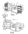
- Fig. 1 illustrates a muffler constructed in accordance with a first embodiment of the present invention having an outer shell shown partially in cross-section and with portions partially removed and a first perforated pipe with a fill opening into which a fibrous material filling nozzle extends; and
- Fig. 2 is a perspective view of the shaped tool and muffler insert used to form the filled and wrapped muffler insert of Fig. 1;
- Figs. 3-7 are perspective views of unfilled muffler inserts according to alternative preferred embodiments of the present invention;
- Fig. 8 is a perspective view of a shaped tool and filled muffler insert according to another preferred embodiment of the present invention;
- Fig. 9 illustrates a muffler insert having a plurality of perforations on a partition plate according to another preferred embodiment of the present invention;
- Figs. 10 and 11 illustrates perspective views of a winding device used to form a filled and wound muffler insert according to a preferred embodiment of the present invention;
- Fig. 12 illustrates a perspective view of one preferred process for introducing a filled and wound insert within a previously formed muffler shell to form the muffler of Fig. 1;
- Fig. 13 illustrates a perspective view of a second preferred process for coupling a muffler shell around the filled and wound insert to form the muffler as illustrate in Fig. 1; and
- Fig. 14 is a perspective view of a fiber-encased blank.
- A process is provided for filling a muffler with fibrous material. Mufflers filled in accordance with the present invention are capable of being incorporated into vehicle exhaust systems and function as acoustic energy dissipaters (sound dampeners). Referring now to Fig. 1, a
muffler 15 is illustrated which is capable of being filled in accordance with a first embodiment of the present invention. Themuffler 15 comprises a closedouter shell 12 having first, second andthird partitions 14a-14c which define first, second, third and fourth internal compartments 16a-16d of aninner cavity 12a within themuffler shell 12. A "closed muffler shell" as used herein means a single element muffler shell or a shell formed from two or more elements which are welded or otherwise coupled together such that they are not intended to be opened after introduction of afibrous filling material 24. Themuffler 15 further comprises first, second and thirdperforated pipes partitions 14a-14c include a plurality of openings 14d permitting gases to pass between the compartments 16a-16d. Further in the illustrated embodiment, the first, second andthird pipes first openings 19 having a cross sectional area of from about 5.0 mm2 to about 25.0 mm2. Theopenings 19 in thepipes openings 19 may also contribute to the exchange of acoustic pressure between thepipes fibrous material 24 that defines a wool-type product 24a in those compartments 16a-16d. The wool-type product 24a is surrounded by a filament or windingyam 26 to form a filled andwound muffler insert 71, the importance of which will be described in detail below. - During operation of a vehicle to which the
muffler 15 is coupled, acoustic energy passes through and from theperforated pipes type product 24a which functions to dissipate a portion of the acoustic energy. Theproduct 24a may potentially function to thermally insulate theouter shell 12 from energy in the form of heat transferred from high temperature exhaust gases passing through thepipes - One preferred offline process for forming filled
muffler insert 70 is shown below in Fig. 2. This filledmuffler insert 70 may be subsequently wound with ayarn thread 26 to form a filled andwound muffler insert 71, which forms the interior of themuffler 15 within themuffler shell 12, as described below in Figs. 10 and 11. - Referring now to Fig. 2, a
shaped tool 50 is provided that contains anunfilled muffler insert 52 consisting of the first, second andthird partitions 14a-14c and first, second and third perforatedpipes shaped tool 50 andunfilled muffler insert 52. Theshaped tool 50 has fillopenings 56 corresponding to each created compartment 16a-16d wherein thefibrous material 24 may be introduced. Theshaped tool 50 preferably has atop portion 50a and abottom portion 50b, the importance of which will be described further below in Figs. 10 and 11. - While the unfilled muffler insert 52 of Fig. 2 is shown in one possible configuration, it is understood that many other possible configurations are possible, thus allowing mufflers of a wide variety of shapes and sizes to be easily produced using the same process. The number of possible configurations is potentially limitless and is dependent upon numerous factors, including but not limited to, the size of vehicle in which the
muffler 15 is installed and the desired acoustical properties derived from themuffler 15. Some of the possibilities are shown in Figs. 3-7. - For example, as shown in Fig. 3, the
unfilled insert 52 could contain multiple pipes and chambers. Further, as shown in Fig. 4-6, a triangular, round and oval shaped insert section having a single pipe and correspondingly shaped partition is shown. In Fig. 7, a clamshell shapedunfilled insert section 52 having a straight pipe, a curved pipe, and a single partition is shown. As is understood by those of ordinary skill, the shaped tool 5 0 is thus sized and shaped with appropriate fill openings to correspond to the respective unfilled muffler inserts 52 of Figs. 4-7. - Referring back to Fig. 2, to fill one or more compartments 16a-16d with
fibrous material 24 to form the filledmuffler insert 70, thenozzle 30 is inserted into arespective fill opening 56 contained within that respective portion of the shapedtool 50. Further, avacuum adapter 40, coupled to avacuum source 42 via ahose 44, is inserted into the end 60 of one of therespective pipes tool 50. Aplug 46 is inserted into theend portion 62 of theother pipes pipes muffler shell 12 through thepipes vacuum source 42 is activated, a partial vacuum is created within the compartments 16a-16d of the shapedtool 50. Prior to or after activation of thevacuum source 42,continuous strand material 24b and pressurized air are supplied to atexturizing device 32. The pressurized air is supplied from aconventional compressor 48 which communicates with thedevice 32 via a hose 48a. Thecontinuous strand material 24b comprises one more strands each which may comprise a plurality of glass filaments selected from the group consisting of E-glass filaments and S-glass filaments. Preferably, the continuous strand material comprises a roving sold by Owens Corning under the trademark ADVANTEX® or the trademark Zentron®. The pressurized air separates and entangles the filaments of thestrand material 24b so that the strand material emerges from thenozzle 30 as a continuous length of "fluffed-up" orfibrous material 24. Once thefibrous material 24 fills the desired compartments 16a-16d, it defines a wool-type product 24a in the compartments 16a-16d. - In alternative embodiments, one of which is shown in Fig. 8, the
vacuum source 42 could also be coupled anywhere along thebottom region 77 of the shapedtool 50 within the lowest compartment 16a-16d and not associated with thepipes end portion 60, 62 of all of thepipes plugs 46. Thus, for example,extra perforations 66 or throughregions 68 in the shapedtool 50 may be provided wherein thehose 44 of thevacuum device 42 may be sealingly engaged so as to provide a sufficient vacuum to allow filling of one or more of the compartments 16a-d withfibrous material 24. - In yet another preferred embodiment, as shown in Fig. 9, one or more of the
partitions 14a-c of theinsert 52 maybe formed withperforations 79 that allow further vacuum effect to enhance the filling of therespective partitions 14a-c. - A sufficient quantity of
fibrous material 24 is provided in one or more of the compartments 16a-16d so as to allow themuffler 15 to adequately perform its acoustic energy attenuation and thermal insulation functions. The compartments 16a-16d may be filled withfibrous material 24 having a density of from about 80 grams/liter to about 200 grams/liter and preferably about 100 grams/liter. - After the
fibrous material 24 is added within the desired compartments 16a-d, thevacuum source 42 and its associated components are removed. The filled insert is then loaded onto a winding device (shown in Figs. 10 and 11 as 100), wherein ayarn thread 26 is then wrapped around thewool type product 24a volume to form a filled and woundmuffler insert 71. The method for wrapping theyarn thread 26 around the wooltype product volume 24a to form the filled and woundinsert 71 is described in further detail in Figs. 10 and 11 below. - The
wound yarn 26, in one preferred embodiment, is selected to provide sufficient tensile strength at room temperature such that the filled and woundinsert 71 may be handled in subsequent processing steps, including but not limited to transporting theinsert 71 or introducing the filled and woundinsert 71 within amuffler shell 12 to form amuffler 15.Yarns 26 with sufficient tensile strength have a tensile strength of at least 550 megapascals (mPa) at room temperature. Further, thewound yarn 26 preferably has a very low tensile strength at elevated temperatures (that is in or around typical muffler operating temperatures) such that the first use of themuffler 15 within a vehicle will disintegrate the wrappingyam 26. This disintegration of thewound yarn 26 will in turn lead to a literal explosion ofwool product 24a within the selected compartment 16a-d. Tensile strengths of a maximum of at most about 50 mPa are desired at these elevated temperatures (between approximately 80 and 120 degrees Celsius). -
Preferred wound yarns 26 that meet the tensile strength criteria desired above include polymer yarns having a fiber diameter of between about 0.2 and 1.0 millimeters. Two preferred polymer wound yarns having these diameters and meeting the tensile strength requirements polypropylene yarns and modified polyethylene yarns. - Alternatively, the
wound yarn 26 may be formed from materials having sufficient tensile strength at room temperatures as described previously and also at elevated temperatures to maintain the fibrouswool type product 24a away from themuffler shell 12. This would allow for a double layer of acoustical protection, one of which is provided by the glass contained within theproduct 24a, and one within the air gap created between theproduct 24a and the muffler shell. As such, thewound yarn 26 does not disintegrate at elevated temperatures. One type ofwound yarn 26 that meets these criteria is a steel-type wound yam 26. - The shaped
tool 50 may then be removed from the filled and woundinsert 71. The filled and woundinsert 71 is subsequently placed within amuffler cavity 12 to form themuffler 15 as described below in further detail in Figs. 12 and 13. - The process and apparatus for wrapping the
yarn 26 around thewool type product 24a and affixing theyarn 26 to form the filled and woundinsert 71 from the filledinsert 70 may be done in many different ways with many different apparatus. One preferred winding device is shown in Figs. 10 and 11, in which the device 100 itself wraps theyarn 26 around the filledinsert 70 while holding the filledinsert 70 stationary. - Referring now to Figs. 10 and 11, a device for winding the
yam thread 26 around the filledinsert 70 according to one preferred embodiment is shown generally as 100. The winding device 100 has a verticallymovable frame 102 coupled to astationary base 112. The vertically movingframe 102 has anupper support stage 104 and amiddle support stage 106. Theupper support stage 104 has ahollow cap 105. Anupper cylinder 157 is contained within thehollow cap 105. Thehollow cap 105 also has astage portion 105a that surrounds an upper portion of thecylinder 157. - A
bottom portion 107 of theframe 102 extends through afirst slot 111 of astationary base 112. Thebottom portion 107 has aring portion 109 having inner teeth (not shown) that are coupled around atubular worm gear 108 of arearward drive actuator 110 that is coupled to thevertical base 102. Thestationary base 112 also has a pair ofvertical side slots 113,115 that receive a pair of respective back frame supports 117, 119 that extend rearward from the vertically movingframe 102 and are coupled to adrive actuator 110. - The winding machine 100 also has a
belt drive actuator 120 having apulley 125 mounted on its top surface. Abelt 121 is coupled to thepulley 125 and to asecond pulley 123 contained on top of themiddle support stage 106. The actuation of thebelt drive actuator 120 rotates thepulley 125, which in turn causes thebelt 121 to turn to rotate thesecond pulley 123. Thesecond pulley 123 is hollow and rotates around acenter axis 132 defined by thecylinder 157. - Also attached to the
pulley 123 is a yarn-guidingframe 140, which similarly rotate in response to the rotation of thepulley 123. A pair ofyarn grippers 142 closely associated with the yarn-guidingframe 140 are coupled to arespective arm 150 that are coupled to thestationary base 112. - Also shown is a pair of
yarn bobbins 144 havingtensioning devices 146 that are coupled to the opposite side of thesecond pulley 123 from the yarn-guidingframe 140.Yarn thread 26 stored on eachbobbin 144 is thus continuously fed from each of the pair ofyarn bobbins 144 through therespective tensioning device 146 and yarn-guidingframe 140 to theyarn gripper 142. As one of ordinary skill appreciates, the number ofbobbins 144, shown in Figs. 10 and 11 as a pair of bobbins, may vary from one bobbin to three or more bobbins depending upon numerous factors, including the size of themuffler insert 24, the space limitations within the winding machines 100, the rotational speed of thebelt drive actuator 120, the efficiency of the winding mechanism, the desired winding thickness of theyarn thread 26, or numerous other factors known to those of ordinary skill in the art. - Coupled beneath the
lower stage 124 is anactuator 122. Theactuator 122 is supported to the rearward mountingstructure 110 by supports 126,128. Alower cylinder 130 is coupled to theactuator 122 and extends upwardly through thelower stage 124. Thelower cylinder 130 is capable of extending upward or downward along acenter axis 132 defined along the length of thecylinder 130 andcylinder 157 when actuated by theactuator 122. - The process for coupling the
yarn 26 around thewool type product 24a of the filledinsert 70 is accomplished by first activating theactuator 110 to rotate theworm gear 108. The movement of theworm gear 108 in turn causes thering portion 109 to move the slightly upwardly in response. The upward movement of thering portion 109 in turn moves the coupled components of the vertically movingframe 102, including the yarn-guidingframe 140, upwardly in response. This creates a gap between thecylinder 157 andcylinder 130 that allows introduction of the shapedinsert 50 onto the winding device 100. The shapedinsert 50 is then placed onto acircular stage 131 located on the top surface of thelower stage 124, such that thecircular stage 131 is either coupled to the bottom of thebottom section 50b of the shapedtool 50 or to one of the pipes (here shown as pipe 18). Theupper section 50a is then coupled to thecylinder 157. - The
actuator 110 is then reactivated to move the coupled components of thevertical frame 102 downwardly. As this occurs, theupper section 50a of the shapedtool 50 moves downwards until its lower surface remains at a distance of approximately 5 to 20 millimeters above the upper section of thelower section 50b. This distance defines acircular gap 175 exposing a portion of the filledinsert 70.Yarn 26 is then wrapped around thewool section 24a of the filledinsert 70 exposed within thegap 175 as described further below. - To begin the winding process, a first end of the
yarn 26 from each of thebobbins 144 through thetensioning devices 146 and coupled to theyam grippers 142. Next, thebelt actuator 120 is activated, causing the rotation of thepulley 123,bobbins 144,tensioning devices 146, andyarn guiding frame 140 around thecenter axis 132.Yarn 26 is then applied around the exposed portion of the filledinsert 70. During the application of theyarn 26 theyarn grippers 142 are tilted slightly downward by means of pneumatic or electrical actuators on thearms 150. Thegrippers 142 then release theyam 26 for the rest of the application process.Actuator 122 is then activated to move thetube member 130 further upwardly to further wrap yarn around new exposed portions of thewool product 24a contained within thegap 175. The combination of both the translation of the filledinsert 70 and the rotation of the yarn with the help of the yarn-guide 140 builds a helicoidal path. The step of this path should be defined to avoid the fibrous material having the ability to spring out of its confined volume (minimum: 5 millimeters; maximum: 30 millimeters). The process is continued until theentire wool product 24a, or a desired portion of thewool product 24a, is sufficiently wrapped inyam 26. Thebelt actuator device 110 is then deactivated. - Next, the
yarn thread 26 located between thewool product 24a and theyarn gripper 142 is cut. - Next, in one preferred method, the end of the
yarn 26 created by this cut is then fused to another portion of theyarn 26 wrapped around thewool product 24a. Alternatively, the ends from eachthread 26 of yam may be tied together or tied to portions ofyarn thread 26 already wrapped around the fiber insert. This forms the filled and woundinsert 71. - The fusion step described above is dependent upon the type of
yarn thread 26 utilized. For a polymer yarn thread, the end of the yarn preferably is made molten using an ultrasonic welding or hot welding process and stuck to another portion of thethread 26. For a metal yarn, a spot welding process may be utilized. - Alternatively, the
yarn thread 26 may be otherwise be affixed around thewool product 24a volume by coupling the end portion of theyarn thread 26 within a portion ofwool type product 24a. - Also, the
yarn thread 26 may simply be maintained in place around thewool type product 24a without the need to affix the end of theyarn thread 26 to itself or to thewool type product 24a. In other words, the yarn thread is self-locking simply by the wrapping mechanism itself without the need to couple the end of theyam thread 26 to prevent unraveling. - In another alternative embodiment, pins (not shown) may be introduced within the
wool type product 24a. Theyarn thread 26 is then wrapped in one direction (clockwise aroundcenter line 132, for example), around thewool type product 24 until encountering the pin. At this time, the yarn thread wraps around the pin and is then wound in the opposite direction (counterclockwise), therein maintaining theyarn thread 26 in place without the need for affixing theyarn thread 26 to itself or to thewool type product 24a. - After the filled and wound
insert 71 is formed, theactuator tool 50 and filled and woundinsert 71 are then removed from the winding device 100 by reactivating theactuator 110 to move upward such that thecylinders tool pieces muffler insert 71 and discarded. - As one of ordinary skill can appreciate, the winding device 100 shown in Figs. 10 and 11 could be configured with a wide variety of modifications and still fall within the spirit of the present invention. For example, the
yarn 26 may be applied to thewool product 24a wherein the shapedtool 50 and filledmuffler insert 70 rotate while theyarn 26 remains substantially stationary. Alternatively, one, three, or more bobbins may be used in place of thedual bobbins 144 shown in Figs. 10 and 11. - In addition, while the process of introducing the
fibrous material 24 to theunfilled insert 50 is shown as an offline process in Fig. 2, the process may actually be performed on the winding device 100 of Figs.10 and 11. In this process, theunfilled insert 52 and shapedtool 50 are introduced to the winding device 100 in a manner similar to that shown in Figs. 10 and 11 with respect to the filledinsert 70 and shapedtool 50. Thefibrous material 24 is then introduced to the respective compartments 16a-d in a manner substantially similar to that shown in Fig. 2 above. After the desired compartments 16a-d are filled to form the filledinsert 71, theyarn thread 26 may be introduced around the filledinsert 71 in a manner described above in Figs. 10 and 11. - By forming the filled insert on the winding machine 100 as in Figs. 10 and 11, and not in an offline process as described above in Fig. 2, additional manufacturing cost savings may be realized. For example, storage costs and transportation costs of the filled insert between the filling line and the winding device 100 may be eliminated. Further, less manufacturing floor space associated with having two separate manufacturing lines may be realized. Further, integrated filling and winding components may also be realized.
- The filled and wound
muffler insert 71 formed in accordance with Figs. 10 and 11 is thus available to be placed within amuffler shell 12 to form themuffler 15. Two alternative approaches may be used to achieve this result. In Fig. 12, the filled and woundinsert 71 is simply pressed into a previously formedmuffler shell 12. In Fig. 13, themuffler shell 12 is formed as two pieces. The filled and woundinsert 71 is then placed within the two pieces and the pieces crimped or welded to form themuffler 15. Each is described below. - Referring now to Fig. 12, one preferred method for forming the
muffler 15 from the filled and woundinsert 71 is shown. In this embodiment, the filled and woundinsert 71 having a constant cross section, such as in the embodiments described in Figs. 3, 4, and 5 above, are pressed within oneend 200 of an appropriately sized cylindrical ortubular muffler shell 12 in a method commonly used by those of ordinary skill in the art. Anend piece 202 may then be sealingly coupled, via welding or crimping, to theopen end 200 of themuffler 12. Asecond end piece 204 is then coupled to the oppositeopen end 201 of theshell 12 to complete the assembly. - Alternatively, as shown in Fig.13, the
muffler shell 12 could be formed as twohalves insert 71 is placed within theinterior region 224 one ofhalves 220. The other of the twohalves 222 is then coupled to the other of the twohalves 220 such that the filled and woundinsert 71 is contained within theinterior region respective halves halves muffler 15 assembly. The technique as shown in Fig. 13 is used primarily to form odd shapedmufflers 15 such as clamshell mufflers, and thus is used with the embodiments as shown in Figs. 7 and 9 above. However, the technique may also be used to form cylindrical or tubular mufflers as formed according to Fig. 12 above, and thus may be used in conjunction with the embodiments shown in Figs. 3-5 above. - The present invention offers many advantages over prior art silencer systems used in mufflers.
- For example, the present invention maybe utilized to form mufflers in a wide variety of shapes and sizes not previously attainable in prior art systems. This is important for two reasons. First, while the filling of prior art mufflers with fibrous material was limited to certain geometries, the present invention allows filling of the interior of the mufflers with fibrous material in virtually any geometry. For example, odd shapes such as clam shaped muffler interiors may be easily filled with fibrous material.
- Second, the filling of the interior region can be done prior to the build-out of an entire muffler cavity, including the introduction and fixing of internal mechanical parts (pipes and partitions) within the outer shell of the muffler. As stated above, this allows mufflers to be formed in a wide variety of odd shapes and sizes not previously attainable due to space constraints and other considerations. Further, by forming a filled and wound insert, as compared with a filled insert as found in the prior art, damage to the muffler shell during the introduction process is minimized. Also, because the filling process can be done on the winding machine itself, manufacturing cost savings in terms of equipment space, storage, and transportation of filled inserts may be realized
- Further, the behavior of the
polymer yam thread 26 in preferred embodiments of the present invention against temperature are selected to provide optimal tensile strength at room temperature and the lowest possible tensile strength at higher temperatures. Thus, thepolymer yarn 26 will disintegrate in the first vehicle use, allowing thewool product 24a to expand and fill the compartment in which it is contained, which improves acoustical properties of themuffler 15. - Also, because the
polymer yarn 26 is located at a position nearer to the muffler shell and away from the pipes, odor associated with the disintegration of thepolymer yarn 26 during first start conditions occurs after the muffler has sufficiently warmed up, thus lessening smoke and odor near the car assembly line. - Also, additional acoustical advantages may be provided in alternative preferred embodiments utilizing steel yarn as the winding. In these systems, the steel yam compresses the fibrous material against the unfilled insert, therein creating a "double layer" of acoustical properties within the muffler shell contributed by the fibrous material and air gap. This also may enable savings in raw material costs.
- As shown in Fig. 14, the technology used to form the filled and wound
insert 71 above may also be used to form filled and wound fiber-encasedblanks 300. In this embodiment, acore material 302 of metal, plastic, wood, or any other material replaces theunfilled insert 52 of Figs. 3-7 and 9. Thecore material 302 is wrapped withfibrous material 24 and wound withyam 26 in a manner substantially similar to that described above in Figs. 2, 10 and 11. The composition of theyam thread 26 should have sufficiently high tensile strength (above 550 mPa) at room temperature and at elevated temperatures to remain wrapped around thefibrous material 24 during storage and during subsequent processing to form the end use application. Theblanks 300 may then be used for many applications, including for use as structural reinforcements in any number of applications. To the extreme, thiscore material 302 could be only in the shape of a temporary double pin. The fibrous material consolidated by the yarn are then pulled off while the assembly (fibrous material 24 + yarn 26) remains stable.
Claims (23)
- A filled and wound muffler insert (71) for use in a muffler (15) comprising:a filled insert (70) comprising at least one pipe (18) and a wool-type product (24a), said wool-type product surrounding a portion of said at least one pipe; anda yarn thread (26) wrapped around and secured to an outer portion of said wool-type product.
- The insert of claim 1, wherein at least one of said at least one pipe(s) comprises a perforated pipe.
- The insert of claim 1 or claim 2, wherein said filled insert further comprises at least one partition(s) (14a) coupled to said at least one pipe.
- The insert of claim 3, wherein at least one of said partitions comprises a perforated partition.
- The insert of any preceding claim, wherein said yarn thread comprises a polymer yarn thread having a tensile strength at room temperature of at least 550 megapascals and having a tensile strength at temperatures greater than about 80 degrees Celsius of at most 50 megapascals.
- The insert of claim 5, wherein said polymer yarn thread is selected from polypropylene yarn thread and modified polyethylene.
- The insert of claim 5 or claim 6, wherein said polymer yarn thread has a fiber diameter of between approximately 0.2 and 1.0 millimeters.
- The insert of any of claims 1 to 4, wherein said yarn thread comprises a steel yarn thread.
- The insert of any preceding claim, wherein said wool-type product comprises one or more strands of a continuous strand material.
- The insert of claim 9, wherein said continuous strand material comprises one or more strands each comprising a plurality of glass filaments selected from E-glass filaments and S-glass filaments.
- A method for forming a filled and wound muffler insert (71) according to claim 1 comprising:providing an unfilled muffler insert (52);coupling said unfilled muffler insert within a shaped tool (50), said.shaped tool having an upper section (50a) and a lower section (50b), said shaped tool and said unfilled muffler insert defining at least one compartment (16a-d) there between;introducing a fibrous material (24) within one of said at least one compartment to form a filled insert;placing said filled insert onto a winding machine (100), including a center axis (132); moving said upper section of said shaped tool away from said lower section along said center axis to create a gap (175);wrapping a yam thread (26) around a portion of said filled insert exposed within said gap to form the filled and wound muffler insert;removing said shaped tool and the filled and wound muffler insert from said winding tool; andextracting the filled and wound muffler insert from said shaped tool.
- The method of claim 11, wherein introducing a fibrous material comprises:introducing a nozzle (30) ofa texturizing device (32) within a fill opening (56) of said shaped tool;introducing one or more strands of a continuous strand material (24) from said texturizing device through said nozzle and into said compartment under vacuum pressure.
- The method of claim 11 or claim 12, wherein wrapping a yarn thread comprises:coupling said yam thread contained on said winding machine to a gripper (142) located at a position near said gap;rotating a portion of said winding machine around said filled insert such that said yam thread is wound onto said filled insert; andcutting said yarn thread between said filled insert and said winding machine.
- The method of claim 13 further comprising affixing said yarn thread around said filled insert.
- The method of claim 14, wherein affixing said yarn thread around said filled insert comprises affixing said end to said another portion of said yarn thread.
- The method of claim 15, wherein affixing said end comprises ultrasonically welding said end to said another portion of said yam thread.
- The method of claim 15, wherein affixing said end comprises hot welding said end to said another portion of said yam thread.
- The method of claim 15, wherein affixing said yarn thread around said filled insert comprises knotting said end of said yam thread to said another portion of said yam thread.
- The method of claim 14, wherein affixing said yarn thread around said filled insert comprises affixing said end within said fibrous portion.
- A method for forming a muffler (15) comprising:forming a filled and wound muffler insert by a method as claimed in any one of claims 11 to 18, andcoupling said filled and wound muffler insert within a muffler shell (12).
- The method of claim 20, wherein coupling said filled and wound muffler insert within a muffler shell comprises:providing a muffler shell (12) having a pair of open ends and an interior region;providing a pair of end pieces (202, 204);pressing said filled and wound muffler insert through said open end and within said interior region;coupling one of said pair of end pieces to one of said pair of open ends;coupling the other of said pair of end pieces to the other of said pair of open ends;sealingly affixing said one of said pair of end pieces to said one of said pair of open ends; andsealingly affixing said other of said pair of end pieces to said other of said pair of open ends.
- The method of claim 20, wherein coupling said filled and wound muffler insert within a muffler shell comprises:providing a muffler shell having an interior region and a first end and second end; andcoupling said muffler shell around said filled and wound muffler insert such that said filled and wound muffler insert is substantially contained within said interior region and such that said first end substantially abuts said second end; andsealingly affixing said first end to said second end.
- The method of claim 20 further comprising moving said filled insert and said bottom portion of said shaped tool upward or downward along said center axis.
Applications Claiming Priority (2)
| Application Number | Priority Date | Filing Date | Title |
|---|---|---|---|
| US10/613,873 US7077922B2 (en) | 2003-07-02 | 2003-07-02 | Technique to fill silencers |
| PCT/EP2004/007484 WO2005005796A1 (en) | 2003-07-02 | 2004-07-02 | Muffler insert and method |
Publications (2)
| Publication Number | Publication Date |
|---|---|
| EP1651844A1 EP1651844A1 (en) | 2006-05-03 |
| EP1651844B1 true EP1651844B1 (en) | 2007-10-24 |
Family
ID=33552785
Family Applications (1)
| Application Number | Title | Priority Date | Filing Date |
|---|---|---|---|
| EP04763126A Expired - Lifetime EP1651844B1 (en) | 2003-07-02 | 2004-07-02 | Muffler insert and method |
Country Status (5)
| Country | Link |
|---|---|
| US (1) | US7077922B2 (en) |
| EP (1) | EP1651844B1 (en) |
| AT (1) | ATE376616T1 (en) |
| DE (1) | DE602004009691T2 (en) |
| WO (1) | WO2005005796A1 (en) |
Cited By (1)
| Publication number | Priority date | Publication date | Assignee | Title |
|---|---|---|---|---|
| CN110560974A (en) * | 2019-09-12 | 2019-12-13 | 浙江金麦特自动化系统有限公司 | Automatic welding system for automobile silencer |
Families Citing this family (19)
| Publication number | Priority date | Publication date | Assignee | Title |
|---|---|---|---|---|
| US20060081416A1 (en) * | 2004-10-14 | 2006-04-20 | Nentrup Trent L | Exhaust silencer with acoustic damping mat |
| US20070193028A1 (en) * | 2006-02-17 | 2007-08-23 | Luc Brandt | Method for winding a strand of material around a substrate and products formed thereby |
| FR2911165B1 (en) * | 2007-01-10 | 2010-01-22 | Faurecia Sys Echappement | METHOD FOR MANUFACTURING AN EXHAUST ELEMENT OF AN EXHAUST LINE OF A THERMALLY ENGINE VEHICLE AND AN EXHAUST MEMBER, PARTICULARLY OBTAINED BY CARRYING OUT SAID METHOD |
| US7975382B2 (en) * | 2007-10-30 | 2011-07-12 | Ocv Intellectual Capital, Llc | Method for filling a muffler cavity |
| US8590155B2 (en) * | 2009-06-03 | 2013-11-26 | Ocv Intellectual Capital, Llc | Apparatus for and process of filling a muffler with fibrous material utilizing a directional jet |
| US8623263B2 (en) | 2009-08-05 | 2014-01-07 | Ocv Intellectual Capital, Llc | Process for curing a porous muffler preform |
| US20110031660A1 (en) * | 2009-08-05 | 2011-02-10 | Huff Norman T | Method of forming a muffler preform |
| DE102010019959A1 (en) * | 2010-05-08 | 2011-11-10 | J. Eberspächer GmbH & Co. KG | silencer |
| DE102011012156A1 (en) * | 2011-02-23 | 2012-08-23 | Dbw Holding Gmbh | Process for the preparation of a molding material made of fiber materials and apparatus therefor |
| DE102011012202B4 (en) | 2011-02-23 | 2014-09-25 | Dbw Holding Gmbh | Silencer insert for motor vehicles and method for the manufacture thereof |
| PL2602370T5 (en) * | 2011-12-07 | 2019-03-29 | So.La.Is Societa' Lavorazione Isolanti S.R.L. A Socio Unico | Method and machine for producing a sound-deadening insert for silencer of an exhaust-gas discharge system of an internal-combustion engine |
| KR101338077B1 (en) * | 2012-02-29 | 2013-12-06 | 현대자동차주식회사 | Muffler for vehicle with dual exhaust gas pipe |
| WO2016145244A1 (en) * | 2015-03-11 | 2016-09-15 | Ocv Intellectual Capital, Llc | Methods and systems for filling mufflers with fibrous material |
| ITUA20161725A1 (en) * | 2016-03-16 | 2017-09-16 | So La Is Soc Lavorazione Isolanti S R L Con Unico Socio | METHOD FOR REALIZING A FIBER MATTRESS TO ACOUSTICALLY AND / OR THERMICALLY INSULATE A COMPONENT OF A MOTOR VEHICLE |
| JP6504141B2 (en) | 2016-10-17 | 2019-04-24 | スズキ株式会社 | Vehicle exhaust system |
| EP3336326A1 (en) | 2016-12-19 | 2018-06-20 | OCV Intellectual Capital, LLC | Systems for and methods of filling mufflers with fibrous material |
| JP7195183B2 (en) * | 2019-03-06 | 2022-12-23 | 三恵技研工業株式会社 | Silencer and its manufacturing method |
| CN111554260B (en) * | 2020-05-09 | 2023-01-17 | 安徽三星环保工程有限公司 | Ventilation and noise reduction module |
| JP7260511B2 (en) * | 2020-08-07 | 2023-04-18 | 株式会社ユタカ技研 | How to fill a silencer with sound absorbing material |
Family Cites Families (32)
| Publication number | Priority date | Publication date | Assignee | Title |
|---|---|---|---|---|
| US4121686A (en) | 1977-06-09 | 1978-10-24 | Keller Jr Moreau A | Hollow sound-dampened structure |
| SE445942B (en) | 1982-04-06 | 1986-07-28 | Volvo Ab | Muffler AND METHOD AND DEVICE FOR MANUFACTURING THIS |
| EP0146249B1 (en) | 1983-11-18 | 1989-01-18 | TBA Industrial Products Limited | Glass fibre products |
| US5643464A (en) * | 1988-11-21 | 1997-07-01 | Collagen Corporation | Process for preparing a sterile, dry crosslinking agent |
| GB2238735A (en) | 1989-12-09 | 1991-06-12 | Walker Uk Limited | Silencer and method of producing same |
| US5712086A (en) * | 1990-05-15 | 1998-01-27 | New York Blood Center, Inc. | Process for transfusing cell containing fractions sterilized with radiation and a quencher of type I and type II photodynamic reactions |
| US5981163A (en) * | 1990-05-15 | 1999-11-09 | New York Blood Center, Inc. | Process for the sterilization of biological compositions using irradiation and quenchers of type I and type II photodynamic reactions |
| JPH076377B2 (en) | 1990-05-30 | 1995-01-30 | 日本グラスファイバー工業株式会社 | Silencer for internal combustion engine |
| US6203755B1 (en) * | 1994-03-04 | 2001-03-20 | St. Jude Medical, Inc. | Electron beam sterilization of biological tissues |
| DE69534187T2 (en) * | 1994-05-13 | 2005-11-17 | Miltenyi Biotec Gmbh | STERILE AND PYROGEN-FREE COLUMNS COUPLED WITH A PROTEIN FOR BINDING AND REMOVING SUBSTANCES FROM THE BLOOD |
| SE9401986D0 (en) * | 1994-06-08 | 1994-06-08 | Pharmacia Ab | New process for sterilization and articles sterilized thereby |
| US5837313A (en) * | 1995-04-19 | 1998-11-17 | Schneider (Usa) Inc | Drug release stent coating process |
| JP3799626B2 (en) * | 1995-04-25 | 2006-07-19 | 有限会社ナイセム | Cardiovascular repair material and method for producing the same |
| US6049025A (en) * | 1995-09-15 | 2000-04-11 | Stone; Kevin R. | Articular cartilage xenografts |
| US5691152A (en) * | 1995-11-09 | 1997-11-25 | E. R. Squibb & Sons, Inc. | Stable avidin composition |
| US5730933A (en) * | 1996-04-16 | 1998-03-24 | Depuy Orthopaedics, Inc. | Radiation sterilization of biologically active compounds |
| JP2001505960A (en) | 1996-12-02 | 2001-05-08 | オウェンス コーニング | Molded insulation products and their production using continuous wool fibers |
| US5856172A (en) * | 1997-01-03 | 1999-01-05 | Quality Technologies, Llc | Preservation of microorganisms in a vial with a cap comprising an immobilized desiccant |
| US5926954A (en) | 1997-09-10 | 1999-07-27 | Acoust-A-Fiber Research & Development, Inc. | Method of making a silencer |
| US6010719A (en) * | 1997-09-16 | 2000-01-04 | Universiteit Gent | Freeze-dried disintegrating tablets |
| DE59813552D1 (en) | 1997-12-24 | 2006-06-29 | Eberspaecher J Gmbh & Co | Method for producing an absorption silencer |
| US6053276A (en) | 1998-06-09 | 2000-04-25 | D'amico, Jr.; John | Muffler packing method with injection of cartrided continuous filament fiberglass |
| US6148519A (en) | 1998-09-18 | 2000-11-21 | Donaldson Company, Inc. | Apparatus for installing a packing material in a muffler assembly; and methods thereof |
| US6094817A (en) | 1998-10-15 | 2000-08-01 | Acoust-A-Fiber Research And Development, Inc. | Method for filling a silencer with sound insulating material |
| US6317959B1 (en) | 1999-02-16 | 2001-11-20 | Owens Corning Sweden A.B. | Process and apparatus for packing insulation material in a passage between first and second elements |
| US6196351B1 (en) | 1999-06-04 | 2001-03-06 | Lancaster Glass Fibre Limited | Silencer cartridge |
| US6370747B1 (en) | 2000-09-13 | 2002-04-16 | Owens Corning Fiberglas Technology, Inc. | Method and apparatus for the bulk collection of texturized strand |
| US6467571B2 (en) | 2000-12-11 | 2002-10-22 | Nakagawa Sangyo Co., Ltd. | Sound absorbing material, muffler using the sound absorbing material, and method for forming sound absorbing layer thereof |
| US6412596B1 (en) | 2001-02-01 | 2002-07-02 | Owens Corning Composites Sprl | Process for filling a muffler and muffler filled with fibrous material |
| US6446750B1 (en) | 2001-03-16 | 2002-09-10 | Owens Corning Fiberglas Technology, Inc. | Process for filling a muffler shell with fibrous material |
| US6581723B2 (en) * | 2001-08-31 | 2003-06-24 | Owens Corning Composites Sprl | Muffler shell filling process, muffler filled with fibrous material and vacuum filling device |
| US6607052B2 (en) * | 2001-09-12 | 2003-08-19 | Owens Corning Composites Sprl | Muffler shell filling process and muffler filled with fibrous material |
-
2003
- 2003-07-02 US US10/613,873 patent/US7077922B2/en not_active Expired - Fee Related
-
2004
- 2004-07-02 DE DE602004009691T patent/DE602004009691T2/en not_active Expired - Fee Related
- 2004-07-02 WO PCT/EP2004/007484 patent/WO2005005796A1/en not_active Ceased
- 2004-07-02 EP EP04763126A patent/EP1651844B1/en not_active Expired - Lifetime
- 2004-07-02 AT AT04763126T patent/ATE376616T1/en not_active IP Right Cessation
Cited By (1)
| Publication number | Priority date | Publication date | Assignee | Title |
|---|---|---|---|---|
| CN110560974A (en) * | 2019-09-12 | 2019-12-13 | 浙江金麦特自动化系统有限公司 | Automatic welding system for automobile silencer |
Also Published As
| Publication number | Publication date |
|---|---|
| US20050001012A1 (en) | 2005-01-06 |
| ATE376616T1 (en) | 2007-11-15 |
| DE602004009691D1 (en) | 2007-12-06 |
| WO2005005796A1 (en) | 2005-01-20 |
| DE602004009691T2 (en) | 2008-08-28 |
| US7077922B2 (en) | 2006-07-18 |
| EP1651844A1 (en) | 2006-05-03 |
Similar Documents
| Publication | Publication Date | Title |
|---|---|---|
| US7077922B2 (en) | Technique to fill silencers | |
| US6319444B1 (en) | Molded insulation products and their manufacture using continuous-filament wool | |
| US6412596B1 (en) | Process for filling a muffler and muffler filled with fibrous material | |
| CA1229307A (en) | Container through which a gas flows, preferably a muffler, with fiberglass filling and method and apparatus for filling the same | |
| US6607052B2 (en) | Muffler shell filling process and muffler filled with fibrous material | |
| MXPA99005139A (en) | Method and apparatus for making preforms from glass fiber strand material. | |
| US6581723B2 (en) | Muffler shell filling process, muffler filled with fibrous material and vacuum filling device | |
| US6094817A (en) | Method for filling a silencer with sound insulating material | |
| WO2002075122A1 (en) | Process for filling a muffler shell with fibrous material | |
| US6457555B1 (en) | Sound muffling material and method of making thereof | |
| EP1301694B1 (en) | A multiple layer fiber filled sound absorber and a method of manufacturing the same | |
| US7165648B2 (en) | Method for containing an acoustical material within an assembly | |
| JPH11324642A (en) | Filling member for muffler and its forming method | |
| WO2002022928A2 (en) | A method and apparatus for the bulk collection of texturized strand | |
| AU2001276892A1 (en) | A multiple layer fiber filled sound absorber and a method of manufacturing the same | |
| JP5771209B2 (en) | Apparatus and method for manufacturing low entangled bulky roving | |
| JP2000356119A (en) | Silencing material, muffler using it, and method of forming silencing layer thereof | |
| JP2002523663A (en) | Silencer cartridge | |
| AU745570B2 (en) | Method and apparatus for making preforms from glass fiber strand material | |
| ITVE20000035A1 (en) | PROCEDURE FOR MAKING COATINGS FOR EXHAUSTS, EQUIPMENT FOR IMPLEMENTING THE PROCEDURE, AND MANUFACTURE OBTAINED WITH THE PROCEDURE |
Legal Events
| Date | Code | Title | Description |
|---|---|---|---|
| PUAI | Public reference made under article 153(3) epc to a published international application that has entered the european phase |
Free format text: ORIGINAL CODE: 0009012 |
|
| 17P | Request for examination filed |
Effective date: 20060130 |
|
| AK | Designated contracting states |
Kind code of ref document: A1 Designated state(s): AT BE BG CH CY CZ DE DK EE ES FI FR GB GR HU IE IT LI LU MC NL PL PT RO SE SI SK TR |
|
| DAX | Request for extension of the european patent (deleted) | ||
| 17Q | First examination report despatched |
Effective date: 20060503 |
|
| GRAP | Despatch of communication of intention to grant a patent |
Free format text: ORIGINAL CODE: EPIDOSNIGR1 |
|
| GRAS | Grant fee paid |
Free format text: ORIGINAL CODE: EPIDOSNIGR3 |
|
| GRAA | (expected) grant |
Free format text: ORIGINAL CODE: 0009210 |
|
| AK | Designated contracting states |
Kind code of ref document: B1 Designated state(s): AT BE BG CH CY CZ DE DK EE ES FI FR GB GR HU IE IT LI LU MC NL PL PT RO SE SI SK TR |
|
| REG | Reference to a national code |
Ref country code: GB Ref legal event code: FG4D |
|
| REG | Reference to a national code |
Ref country code: CH Ref legal event code: EP |
|
| REG | Reference to a national code |
Ref country code: IE Ref legal event code: FG4D |
|
| REF | Corresponds to: |
Ref document number: 602004009691 Country of ref document: DE Date of ref document: 20071206 Kind code of ref document: P |
|
| NLV1 | Nl: lapsed or annulled due to failure to fulfill the requirements of art. 29p and 29m of the patents act | ||
| PG25 | Lapsed in a contracting state [announced via postgrant information from national office to epo] |
Ref country code: CH Free format text: LAPSE BECAUSE OF FAILURE TO SUBMIT A TRANSLATION OF THE DESCRIPTION OR TO PAY THE FEE WITHIN THE PRESCRIBED TIME-LIMIT Effective date: 20071024 Ref country code: SE Free format text: LAPSE BECAUSE OF FAILURE TO SUBMIT A TRANSLATION OF THE DESCRIPTION OR TO PAY THE FEE WITHIN THE PRESCRIBED TIME-LIMIT Effective date: 20080124 Ref country code: NL Free format text: LAPSE BECAUSE OF FAILURE TO SUBMIT A TRANSLATION OF THE DESCRIPTION OR TO PAY THE FEE WITHIN THE PRESCRIBED TIME-LIMIT Effective date: 20071024 Ref country code: ES Free format text: LAPSE BECAUSE OF FAILURE TO SUBMIT A TRANSLATION OF THE DESCRIPTION OR TO PAY THE FEE WITHIN THE PRESCRIBED TIME-LIMIT Effective date: 20080204 Ref country code: LI Free format text: LAPSE BECAUSE OF FAILURE TO SUBMIT A TRANSLATION OF THE DESCRIPTION OR TO PAY THE FEE WITHIN THE PRESCRIBED TIME-LIMIT Effective date: 20071024 |
|
| REG | Reference to a national code |
Ref country code: CH Ref legal event code: PL |
|
| PG25 | Lapsed in a contracting state [announced via postgrant information from national office to epo] |
Ref country code: BG Free format text: LAPSE BECAUSE OF FAILURE TO SUBMIT A TRANSLATION OF THE DESCRIPTION OR TO PAY THE FEE WITHIN THE PRESCRIBED TIME-LIMIT Effective date: 20080124 Ref country code: SI Free format text: LAPSE BECAUSE OF FAILURE TO SUBMIT A TRANSLATION OF THE DESCRIPTION OR TO PAY THE FEE WITHIN THE PRESCRIBED TIME-LIMIT Effective date: 20071024 Ref country code: PT Free format text: LAPSE BECAUSE OF FAILURE TO SUBMIT A TRANSLATION OF THE DESCRIPTION OR TO PAY THE FEE WITHIN THE PRESCRIBED TIME-LIMIT Effective date: 20080324 Ref country code: PL Free format text: LAPSE BECAUSE OF FAILURE TO SUBMIT A TRANSLATION OF THE DESCRIPTION OR TO PAY THE FEE WITHIN THE PRESCRIBED TIME-LIMIT Effective date: 20071024 |
|
| PG25 | Lapsed in a contracting state [announced via postgrant information from national office to epo] |
Ref country code: AT Free format text: LAPSE BECAUSE OF FAILURE TO SUBMIT A TRANSLATION OF THE DESCRIPTION OR TO PAY THE FEE WITHIN THE PRESCRIBED TIME-LIMIT Effective date: 20071024 |
|
| ET | Fr: translation filed | ||
| PG25 | Lapsed in a contracting state [announced via postgrant information from national office to epo] |
Ref country code: DK Free format text: LAPSE BECAUSE OF FAILURE TO SUBMIT A TRANSLATION OF THE DESCRIPTION OR TO PAY THE FEE WITHIN THE PRESCRIBED TIME-LIMIT Effective date: 20071024 Ref country code: CZ Free format text: LAPSE BECAUSE OF FAILURE TO SUBMIT A TRANSLATION OF THE DESCRIPTION OR TO PAY THE FEE WITHIN THE PRESCRIBED TIME-LIMIT Effective date: 20071024 |
|
| PG25 | Lapsed in a contracting state [announced via postgrant information from national office to epo] |
Ref country code: BE Free format text: LAPSE BECAUSE OF FAILURE TO SUBMIT A TRANSLATION OF THE DESCRIPTION OR TO PAY THE FEE WITHIN THE PRESCRIBED TIME-LIMIT Effective date: 20071024 Ref country code: RO Free format text: LAPSE BECAUSE OF FAILURE TO SUBMIT A TRANSLATION OF THE DESCRIPTION OR TO PAY THE FEE WITHIN THE PRESCRIBED TIME-LIMIT Effective date: 20071024 Ref country code: SK Free format text: LAPSE BECAUSE OF FAILURE TO SUBMIT A TRANSLATION OF THE DESCRIPTION OR TO PAY THE FEE WITHIN THE PRESCRIBED TIME-LIMIT Effective date: 20071024 |
|
| PLBE | No opposition filed within time limit |
Free format text: ORIGINAL CODE: 0009261 |
|
| STAA | Information on the status of an ep patent application or granted ep patent |
Free format text: STATUS: NO OPPOSITION FILED WITHIN TIME LIMIT |
|
| 26N | No opposition filed |
Effective date: 20080725 |
|
| PGFP | Annual fee paid to national office [announced via postgrant information from national office to epo] |
Ref country code: DE Payment date: 20080711 Year of fee payment: 5 |
|
| PGFP | Annual fee paid to national office [announced via postgrant information from national office to epo] |
Ref country code: FR Payment date: 20080718 Year of fee payment: 5 |
|
| PG25 | Lapsed in a contracting state [announced via postgrant information from national office to epo] |
Ref country code: GR Free format text: LAPSE BECAUSE OF FAILURE TO SUBMIT A TRANSLATION OF THE DESCRIPTION OR TO PAY THE FEE WITHIN THE PRESCRIBED TIME-LIMIT Effective date: 20080125 |
|
| PG25 | Lapsed in a contracting state [announced via postgrant information from national office to epo] |
Ref country code: FI Free format text: LAPSE BECAUSE OF FAILURE TO SUBMIT A TRANSLATION OF THE DESCRIPTION OR TO PAY THE FEE WITHIN THE PRESCRIBED TIME-LIMIT Effective date: 20071024 |
|
| GBPC | Gb: european patent ceased through non-payment of renewal fee |
Effective date: 20080702 |
|
| PG25 | Lapsed in a contracting state [announced via postgrant information from national office to epo] |
Ref country code: MC Free format text: LAPSE BECAUSE OF NON-PAYMENT OF DUE FEES Effective date: 20080731 |
|
| PG25 | Lapsed in a contracting state [announced via postgrant information from national office to epo] |
Ref country code: EE Free format text: LAPSE BECAUSE OF FAILURE TO SUBMIT A TRANSLATION OF THE DESCRIPTION OR TO PAY THE FEE WITHIN THE PRESCRIBED TIME-LIMIT Effective date: 20071024 |
|
| PG25 | Lapsed in a contracting state [announced via postgrant information from national office to epo] |
Ref country code: GB Free format text: LAPSE BECAUSE OF NON-PAYMENT OF DUE FEES Effective date: 20080702 |
|
| PG25 | Lapsed in a contracting state [announced via postgrant information from national office to epo] |
Ref country code: CY Free format text: LAPSE BECAUSE OF FAILURE TO SUBMIT A TRANSLATION OF THE DESCRIPTION OR TO PAY THE FEE WITHIN THE PRESCRIBED TIME-LIMIT Effective date: 20071024 Ref country code: IE Free format text: LAPSE BECAUSE OF NON-PAYMENT OF DUE FEES Effective date: 20080702 |
|
| REG | Reference to a national code |
Ref country code: FR Ref legal event code: ST Effective date: 20100331 |
|
| PG25 | Lapsed in a contracting state [announced via postgrant information from national office to epo] |
Ref country code: FR Free format text: LAPSE BECAUSE OF NON-PAYMENT OF DUE FEES Effective date: 20090731 |
|
| PG25 | Lapsed in a contracting state [announced via postgrant information from national office to epo] |
Ref country code: DE Free format text: LAPSE BECAUSE OF NON-PAYMENT OF DUE FEES Effective date: 20100202 |
|
| PG25 | Lapsed in a contracting state [announced via postgrant information from national office to epo] |
Ref country code: HU Free format text: LAPSE BECAUSE OF FAILURE TO SUBMIT A TRANSLATION OF THE DESCRIPTION OR TO PAY THE FEE WITHIN THE PRESCRIBED TIME-LIMIT Effective date: 20080425 Ref country code: LU Free format text: LAPSE BECAUSE OF NON-PAYMENT OF DUE FEES Effective date: 20080702 |
|
| PG25 | Lapsed in a contracting state [announced via postgrant information from national office to epo] |
Ref country code: TR Free format text: LAPSE BECAUSE OF FAILURE TO SUBMIT A TRANSLATION OF THE DESCRIPTION OR TO PAY THE FEE WITHIN THE PRESCRIBED TIME-LIMIT Effective date: 20071024 |
|
| PG25 | Lapsed in a contracting state [announced via postgrant information from national office to epo] |
Ref country code: IT Free format text: LAPSE BECAUSE OF NON-PAYMENT OF DUE FEES Effective date: 20080731 |