EP1650613A1 - An image forming apparatus mounted with an open and close unit - Google Patents
An image forming apparatus mounted with an open and close unit Download PDFInfo
- Publication number
- EP1650613A1 EP1650613A1 EP05022877A EP05022877A EP1650613A1 EP 1650613 A1 EP1650613 A1 EP 1650613A1 EP 05022877 A EP05022877 A EP 05022877A EP 05022877 A EP05022877 A EP 05022877A EP 1650613 A1 EP1650613 A1 EP 1650613A1
- Authority
- EP
- European Patent Office
- Prior art keywords
- image forming
- forming apparatus
- recording medium
- open
- frame plate
- Prior art date
- Legal status (The legal status is an assumption and is not a legal conclusion. Google has not performed a legal analysis and makes no representation as to the accuracy of the status listed.)
- Granted
Links
- 230000007246 mechanism Effects 0.000 claims abstract description 61
- 238000000034 method Methods 0.000 claims description 7
- 239000000463 material Substances 0.000 claims description 2
- 239000011347 resin Substances 0.000 claims description 2
- 229920005989 resin Polymers 0.000 claims description 2
- 238000007599 discharging Methods 0.000 description 9
- 238000004140 cleaning Methods 0.000 description 5
- 230000005540 biological transmission Effects 0.000 description 4
- 230000003287 optical effect Effects 0.000 description 4
- 230000008901 benefit Effects 0.000 description 3
- 239000011521 glass Substances 0.000 description 2
- 238000012423 maintenance Methods 0.000 description 1
- 239000007769 metal material Substances 0.000 description 1
- 238000012986 modification Methods 0.000 description 1
- 230000004048 modification Effects 0.000 description 1
- 230000008569 process Effects 0.000 description 1
- 230000009467 reduction Effects 0.000 description 1
- 230000008439 repair process Effects 0.000 description 1
Images




Classifications
-
- G—PHYSICS
- G03—PHOTOGRAPHY; CINEMATOGRAPHY; ANALOGOUS TECHNIQUES USING WAVES OTHER THAN OPTICAL WAVES; ELECTROGRAPHY; HOLOGRAPHY
- G03G—ELECTROGRAPHY; ELECTROPHOTOGRAPHY; MAGNETOGRAPHY
- G03G15/00—Apparatus for electrographic processes using a charge pattern
- G03G15/22—Apparatus for electrographic processes using a charge pattern involving the combination of more than one step according to groups G03G13/02 - G03G13/20
- G03G15/23—Apparatus for electrographic processes using a charge pattern involving the combination of more than one step according to groups G03G13/02 - G03G13/20 specially adapted for copying both sides of an original or for copying on both sides of a recording or image-receiving material
- G03G15/231—Arrangements for copying on both sides of a recording or image-receiving material
- G03G15/232—Arrangements for copying on both sides of a recording or image-receiving material using a single reusable electrographic recording member
- G03G15/234—Arrangements for copying on both sides of a recording or image-receiving material using a single reusable electrographic recording member by inverting and refeeding the image receiving material with an image on one face to the recording member to transfer a second image on its second face, e.g. by using a duplex tray; Details of duplex trays or inverters
-
- G—PHYSICS
- G03—PHOTOGRAPHY; CINEMATOGRAPHY; ANALOGOUS TECHNIQUES USING WAVES OTHER THAN OPTICAL WAVES; ELECTROGRAPHY; HOLOGRAPHY
- G03G—ELECTROGRAPHY; ELECTROPHOTOGRAPHY; MAGNETOGRAPHY
- G03G21/00—Arrangements not provided for by groups G03G13/00 - G03G19/00, e.g. cleaning, elimination of residual charge
- G03G21/16—Mechanical means for facilitating the maintenance of the apparatus, e.g. modular arrangements
- G03G21/1604—Arrangement or disposition of the entire apparatus
- G03G21/1623—Means to access the interior of the apparatus
- G03G21/1638—Means to access the interior of the apparatus directed to paper handling or jam treatment
-
- G—PHYSICS
- G03—PHOTOGRAPHY; CINEMATOGRAPHY; ANALOGOUS TECHNIQUES USING WAVES OTHER THAN OPTICAL WAVES; ELECTROGRAPHY; HOLOGRAPHY
- G03G—ELECTROGRAPHY; ELECTROPHOTOGRAPHY; MAGNETOGRAPHY
- G03G2215/00—Apparatus for electrophotographic processes
- G03G2215/00362—Apparatus for electrophotographic processes relating to the copy medium handling
- G03G2215/00535—Stable handling of copy medium
- G03G2215/00544—Openable part of feed path
-
- G—PHYSICS
- G03—PHOTOGRAPHY; CINEMATOGRAPHY; ANALOGOUS TECHNIQUES USING WAVES OTHER THAN OPTICAL WAVES; ELECTROGRAPHY; HOLOGRAPHY
- G03G—ELECTROGRAPHY; ELECTROPHOTOGRAPHY; MAGNETOGRAPHY
- G03G2221/00—Processes not provided for by group G03G2215/00, e.g. cleaning or residual charge elimination
- G03G2221/16—Mechanical means for facilitating the maintenance of the apparatus, e.g. modular arrangements and complete machine concepts
- G03G2221/1672—Paper handling
- G03G2221/1675—Paper handling jam treatment
-
- G—PHYSICS
- G03—PHOTOGRAPHY; CINEMATOGRAPHY; ANALOGOUS TECHNIQUES USING WAVES OTHER THAN OPTICAL WAVES; ELECTROGRAPHY; HOLOGRAPHY
- G03G—ELECTROGRAPHY; ELECTROPHOTOGRAPHY; MAGNETOGRAPHY
- G03G2221/00—Processes not provided for by group G03G2215/00, e.g. cleaning or residual charge elimination
- G03G2221/16—Mechanical means for facilitating the maintenance of the apparatus, e.g. modular arrangements and complete machine concepts
- G03G2221/1678—Frame structures
- G03G2221/169—Structural door designs
Definitions
- the present invention relates to an image forming apparatus that makes use of an electrophotographic process, such as a copier, printer, facsimile machine, or multifunctional machine including functions of the copier, printer, and/or facsimile machine. More specifically, the present invention relates to an image forming apparatus having image forming units between a pair of frame plates oppositely disposed to each other so that a toner image formed on an image bearing member may be transferred onto a recording medium.
- a background image forming apparatus 100 includes a main body 101, an image scanning mechanism 102 arranged above the main body 101, an automatic document feeder (ADF) 103 arranged above the image scanning mechanism 102, and a duplex print unit 104 at the right-hand side of the main body 102 of the image forming apparatus 100 of Figure 1.
- ADF automatic document feeder
- the main body 10-1 of the image forming apparatus 100 includes a sheet feeding mechanism 105, an image forming mechanism 106 arranged above the sheet feeding mechanism 105, a sheet discharging portion 107 arranged above the image forming mechanism 106, and a sheet conveying path 108.
- the image forming mechanism 106 disposed in the main body 101 of the image forming apparatus 100 is supported by a pair of frame plates (not shown) oppositely disposed to each other at front and rear sides of the image forming apparatus 100.
- the original document is fed through the ADF 103 to the image scanning mechanism 102.
- the image scanning mechanism 102 reads the image data of the original document to form an image in the image forming mechanism 106 according to image data signals.
- a recording medium is fed from one of sheet feeding cassettes in the sheet feeding mechanism 105, is conveyed upward through the sheet conveying path 108 to the main body 101 of the image forming apparatus 100. After the image formed by the image forming mechanism 106 is transferred onto the recording medium, the recording medium is discharged to the sheet discharging portion 107.
- a first image is formed as described above.
- a second image is formed such that the recoding medium having a first image on one side thereof is conveyed to the duplex print unit 104, is reversed to the different surface side orientation, and is supplied to the image forming mechanism 106 of the main body 101 again. After the second image formed by the image forming mechanism 106 is transferred onto the rear side of the recording medium, the recording medium is discharged to the sheet discharging portion 107.
- the image forming apparatus 100 as shown in Figure 1 has the duplex print unit 104 to perform a duplex print operation so that images may be formed on both sides of the recording medium.
- the duplex print unit 104 mounted to the image forming apparatus 100 has a longer path for conveying the recording medium and/or may handle different types or sizes of papers such as recycled papers, quality of which may be degraded. Under the above-described conditions that the duplex print operation is performed with the duplex print unit 104, a paper jam may highly likely be caused.
- the duplex print unit 104 is rotated about a lower portion thereof to open the duplex print unit 104 facing upward as shown in Figure 2.
- An inner cover 109 is then rotated about a lower potion thereof to open to face upward, as shown in Figure 3, so as to remove a jammed recording paper p.
- the duplex print unit 104 includes a conveying member such as a roller for conveying a reversed recording medium having an image on one side thereof, a guiding member for guiding the reversed recording medium, a switching member such as a path selector for switching or selecting a direction of the reversed recording medium, and so on.
- the duplex print unit 104 further includes a drive source such as a drive motor for rotating the conveying member, a solenoid for switching the switching member, and a detecting member for detecting the recording medium during the travel thereof.
- the duplex print unit 104 may tend to become large and heavy, which may cause poor operability of opening and closing the duplex print unit 104 when a paper jam occurs.
- some background image forming apparatuses have been provided with, for example, a damper mechanism and/or a spring to improve the operability of opening and closing the duplex print unit 104.
- a damper mechanism and/or a spring to improve the operability of opening and closing the duplex print unit 104.
- Such structure of the image forming apparatus 100 has a complicated structure, resulting in increase of costs.
- the present invention has been made in view of the above-mentioned circumstances.
- An advantage of the present invention is to provide a novel image forming apparatus capable of effectively improving operability of an open and close unit included in the novel image forming apparatus.
- Another advantage of the present invention is to provide a novel method of mounting the open and close unit on the above-described novel fixing device.
- a novel image forming apparatus includes first and second frame plates, an open and close unit, and a drive controlling mechanism.
- the first and second frame plates are oppositely disposed spacing by a predetermined width from each other, and the second frame plate includes an extended portion horizontally extending by a predetermined length compared with the first frame plate.
- the open and close unit is disposed within an area of the extended portion between the first and second frame plates and is configured to freely open and close with respect to the novel image forming apparatus.
- the open and close unit includes a recording medium conveying system configured to convey a recording medium.
- the drive controlling mechanism is configured to control the recording medium conveying system.
- the extended portion supports a portion of the drive controlling mechanism so as to be separately mounted on a side of the novel image forming apparatus.
- a novel method of mounting an open and close unit on an image forming apparatus includes disposing first and second frame plates oppositely spacing by a predetermined width from each other, the second frame plate comprising an extended portion horizontally extending by a predetermined length compared with the first frame plate, mounting an open and close unit within an area of the extended portion between the first and second frame plates and configured to freely open and close with respect to the image forming apparatus, the open and close unit comprising a recording medium conveying system configured to convey a recording medium, and mounting a portion of a drive controlling mechanism configured to control the recording medium conveying system so that the portion of the drive controlling mechanism is supported separately from the open and close unit.
- the image forming apparatus 1 is a tandem-type electrophotographic image forming apparatus which includes an indirect transfer system.
- the image forming apparatus 1 includes a main body 2 thereof, an image scanning mechanism 3, an automatic document feeder (ADF) 4, and an optional sheet feeding mechanism 5.
- ADF automatic document feeder
- the main body 2 of the image forming apparatus 1 includes two sheet feeding cassettes 21, and sheet discharging trays 27.
- the sheet feeding cassettes 21 serve as a standard sheet feeding mechanism and are loaded with respective stacks of sheets of particular size including a recording sheet (not shown).
- the sheet discharging trays 27 receives the recording sheet discharged or conveyed from the main body 2. Detailed inner structure of the main body 2 will be described later, referring to Figure 5.
- a duplex print unit 92 is mounted as an open and close unit on the right side of the main body 2 of the image forming apparatus 1 in Figure 4. Details of the duplex print unit 92 will be described later, referring to Figure 5.
- the image scanning mechanism 3 is arranged above the main body 2, and includes a contact glass (not shown), and a console display 90.
- the contact glass is mounted on the top of the image scanning mechanism 3.
- the console display 90 is mounted at the front portion of the image forming apparatus 1, substantially horizontally extending toward a front side where a user generally stands to use the image forming apparatus 1.
- the ADF 4 is arranged above the image scanning mechanism 3.
- the ADF 4 is disposed to be capable of vertically and rotatably opening and closing about a horizontal shaft (serving as a supporting shaft) at a rear end thereof.
- the optional sheet feeding mechanism 5 serves as an optional unit and supports the main body 2, the image scanning mechanism 3, and the ADF 4 thereon.
- the optical sheet feeding mechanism 5 includes two sheet feeding cassettes 91.
- the sheet feeding cassettes 91 are vertically disposed to each other, and are slidable to open at the front side of the optical sheet feeding mechanism 5 for loading and unloading recording sheets.
- the image forming apparatus 1 further includes image forming mechanism 32, an optical writing unit 13, toner replenishing units 28c, 28m, 28y, and 28bk, and the standard sheet feeding mechanism including a sheet conveying part 36.
- the image forming mechanism 32 includes image forming units 10c, 10m, 10y, and 10bk, an intermediate transfer member 15, primary transfer units 16c, 16m, 16y, and 16bk, a secondary transfer unit 25, primary cleaning units 17c, 17m, 17y, and 17bk, and a secondary cleaning unit 18.
- the image forming units 10c, 10m, 10y, and 10bk are separately arranged at positions having horizontal heights or elevations forming a tandem-type image forming mechanism to form cyan images, magenta images, yellow images, and black images, respectively.
- the image forming units 10c, 10m, 10y, and 10bk respectively have drum-shaped image bearing members 11c, 11m, 11y, and 11bk, charging units 12c, 12m, 12y, and 12bk, and developing units 14c, 14m, 14y, and 14bk.
- the charging units 12c, 12m, 12y, and 12bk, and the developing units 14c, 14m, 14y, and 14bk are arranged around the respective image bearing members 11c, 11m, 11y, and 11bk in the respective image forming units 10c, 10m, 10y, and 10bk.
- the image bearing members 11c, 11m, 11y, and 11bk rotate in a clockwise direction in Figure 5.
- the charging units 14c, 14m, 14y, and 14bk uniformly charge respective surfaces of the corresponding image bearing members 11c, 11m, 11y, and 11bk.
- the optical writing unit 13 emits laser light beams Lc, Lm, Ly, and Lbk to irradiate respective surfaces of the corresponding image bearing members 11c, 11m, 11y, and 11bk to form respective electrostatic latent images on the respective surfaces thereof.
- the developing units 14c, 14m, 14y, and 14bk supply respective color toners to the respective surfaces of the image bearing members 11c, 11m, 11y, and 11bk to visualize the respective electrostatic latent images formed on the respective surfaces of the image bearing members 11c, 11m, 11y, and 11bk as respective single toner images.
- the respective developing units 14c, 14m, 14y, and 14bk contain the different colored toners supplied by the toner replenishing units 28c, 28m, 28y, and 28bk.
- the single toner images formed on the respective surfaces of the image bearing members 11c, 11m, 11y, and 11bk are transferred onto a surface of the intermediate transfer member 15 to form an overlaid full color toner image.
- the intermediate transfer member 15 is disposed above the image forming units 10c, 10m, 10y, and 10bk.
- the intermediate transfer member 15 is an endless belt rotating in a counterclockwise direction in Figure 5.
- the intermediate transfer member 15 is held in contact with the primary transferring units 16c, 16m, 16y, and 16bk disposed inside a loop of the intermediate transfer member 15 to face the respective image bearing members 11c, 11m, 11y, and 11bk, which are accommodated in the image forming units 10c, 10m, 10y, and 10bk, respectively.
- the primary transfer units 16c, 16m, 16y, and 16bk form respective primary transfer portions to perform a primary transfer operation.
- the respective single toner images formed on respective surfaces of the image bearing members 11c, 11m, 11y, and 11bk are sequentially transferred onto the surface of the intermediate transfer member 15 that is previously charged.
- the overlaid full color toner image is formed on the surface of the intermediate transfer member 15.
- a recording medium such as a recording sheet is fed from one of the sheet feeding cassettes 21 in the standard sheet feeding mechanism of the image forming apparatus 1.
- the standard sheet feeding mechanism including the sheet conveying part 36 includes the sheet feeding cassettes 21, the recording medium or recording sheet 22, sheet feeding rollers 20, a recording sheet conveying path 23, and a pair of registration rollers 24.
- the image forming apparatus 1 selects one of the sheet feeding cassettes 21 of the main body 2 and the sheet feeding cassettes 91 of the optional sheet feeding mechanism 5 to feed the recording medium 22 therefrom.
- the image forming apparatus 1 selectively rotates the sheet feeding roller 20 at a predetermined timing to feed the recording sheet 22, and conveys the recording sheet 22 through the recording sheet conveying path 23 toward the pair of registration rollers 24.
- the recording sheet conveying path 23 passes the recording sheet 22 therethough.
- the pair of registration rollers 24 supplies the recording sheet 22 in synchronization with respective the movement of the image forming mechanism 32 so that the secondary transfer unit 25 may transfer the full color image formed on the intermediate transfer member 15 onto a proper position of the recording sheet 22.
- the full color toner image on the recording sheet 22 is then conveyed upward through the recording sheet conveying path 23 to be fixed by a fixing unit 30 through application of heat and pressure.
- the recording sheet 22 having the fixed full color image is conveyed by sheet discharging rollers 26 and is discharged to one of the sheet discharging trays 27 arranged on the top portion of the main body 2 of the image forming apparatus 1.
- the duplex print unit 92 includes a switchback path 93, a reverse sheet conveying path 94, a recording medium conveying system 95, and a horizontal shaft 35.
- the recording sheet 22 is conveyed toward a path selector 33.
- the path selector 33 may be switched to allow the recording sheet 22 to go to .the duplex print unit 92.
- the switchback path 93 reverses the recording sheet 22 to the different surface side orientation.
- the reversed recording sheet 22 is then conveyed through the reverse sheet conveying path 94 to a secondary transfer area formed between the intermediate transfer member 15 and the secondary transfer unit 25 of the main body 2 so that a next full color toner image can be transferred onto the rear surface of the recording sheet 22.
- the recording sheet 22 having full color toner images printed on the front and rear sides is conveyed via the fixing unit 30 to one of the sheet discharging trays 27 by the corresponding sheet discharging rollers 26.
- a pair of frame plates or front and rear frame plates 40 and 41 are mounted to the main body 2 in the image forming apparatus 1.
- the front and rear frame plates 40 and 41 are disposed facing each other, having a width W between them as shown in Figure 6.
- the front frame plate 40 is disposed at the front side of the image forming apparatus 1, and the rear frame plate 41 is disposed at a rear side of the image forming apparatus 1.
- the front side is the nearest side from where a user or operator stands when the user operates the image forming apparatus 1.
- the rear side is the farthest side from the user.
- the front and rear frame plates 40 and 41 are engaged with a bottom plate 42 and an intermediate plate 43 to form the frame structure 44 as shown in Figure 6.
- the front and rear frame plates 40 and 41 support the image forming mechanism 32 including the image forming units 10c, 10m, 10y, and 10bk, the intermediate transfer member 15, the primary transfer units 16c, 16m, 16y, and 16bk, the secondary cleaning unit 18, the secondary transfer unit 25 and the like so that the image forming mechanism 32 may be mounted to the frame structure 44.
- the image forming mechanism 32 of Figure 6 employs an indirect transfer method with the tandem type electrophotographic image forming apparatus.
- the image forming mechanism is not limited to be used in the above-described image forming apparatus.
- an embodiment of the present invention can be an image forming apparatus using a direct transfer method or a single image bearing member.
- the rear frame plate 41 has a portion horizontally extended to the right side by a length L, compared with the front frame plate 40.
- the portion extended by the length L is defined as an extended portion 45 (shown in Figures 6 and 7) of the rear frame plate 41.
- the rear frame plate 41 may support drive motors 46 and 47, shown in Figure 6. Details of the drive motors 46 and 47 will be described later.
- the extended portion 45 protrudes at the right side of the main body 2 of the image forming apparatus 1 and forms an area with the length L and the width W.
- the duplex print unit 92 is rotatably mounted within the area of the extended portion 45 with respect to the main body 2 of the image forming apparatus 1, as shown in Figure 7.
- duplex print unit 92 Referring to Figures 8 and 9, the detailed structure of the duplex print unit 92 is described.
- the duplex print unit 92 may pivotably open and close in a vertical manner around the horizontal shaft 35 as shown in Figure 8.
- the duplex print unit 92 is mounted in a proximate outside of the recording sheet conveying path 23 included in the main body 2 of the image forming apparatus 1.
- a jammed paper stuck in the recording sheet conveying path 23 may easily be removed by opening the duplex print unit 92 serving as an open and close unit.
- the duplex print unit 92 may be opened as shown in Figure 9. Opening the duplex print unit 92 may widely expose the sheet conveying part 36 of the main body 2 of the image forming apparatus 1, which allows the user to easily remove the jammed paper from the recording sheet conveying path 23.
- the duplex print unit 92 includes the recording medium conveying system 95 for reversing the recording sheet 22 so that the recording sheet 22 may repeatedly be supplied to the image forming mechanism 32.
- the extended portion 45 of the rear frame plate 41 may support a portion of a drive controlling mechanism that is configured to control the recording medium conveying system 95 to drive. That is, the portion of the drive controlling mechanism may separately be mounted on the extended portion 45 of the rear frame plate 41.
- the drive controlling mechanism includes the drive motor 46, a solenoid, and a detecting member.
- the drive motor 46 drives a conveying member such as rollers and belts included in the recording medium conveying system 95.
- the solenoid switches a switching member such as the path selector 33 for switching or selecting the direction of the recording medium.
- the detecting member detects the recording sheet 22 during the travel of the recording sheet 22.
- the drive motor 47 in Figure 10 drives the pair of registration rollers 24.
- a duct outlet 48 is disposed at the upper portion of the extended portion 45 in an outwardly extending
- the duplex print unit 92 serving as the open and close unit is rotated around the horizontal shaft 35 to be opened outwardly as shown in Figure 9.
- the user may insert his or her hand(s) inside the main body 2 of the image forming apparatus 1 from the front side of the image forming apparatus 1, remove the jammed paper stuck in the recording sheet conveying path 23, and close the duplex print unit 92 as shown in Figure 8.
- duplex print unit 92 Referring to Figure 11, a detailed structure of the duplex print unit 92 is described.
- the duplex print unit 92 includes a drive force transmission unit 96 mounted on the extended portion 45 of the rear frame plate 41.
- the drive force transmission unit 96 includes a plurality of gears 97.
- a motor gear of the drive motor 46 supported by the extended portion 45 may engage with one of the plurality of gears 97 of the drive force transmission unit 96 so that drive force of the drive motor 46 may be transmitted to the conveying member such as the rollers and belts of the recording medium conveying system 95 to rotate the conveying member and convey the recording sheet 22.
- the motor gear of the drive motor 46 may be disengaged from one of the plurality of gears of the drive force transmission unit 96.
- the drive motor 46 is separated from the duplex print unit 92 and is mounted on the rear frame plate 41 of the main body 2 of the image forming apparatus 1, and the duplex print unit 92 without the drive motor 46 thereon is opened and closed with respect to the main body 2 of the image forming apparatus 1.
- the structure of the duplex print unit 92 may not be complicated or increase the cost.
- the duplex print unit 92 having the above-described structure may be made smaller, thereby increasing operability of opening and closing the duplex print unit 92 when the paper jam occurs. Further, the duplex print unit 92 may not be connected to harnesses, thereby increasing reliability of the image forming apparatus 1.
- the front and rear frame plate 40 and 41 are disposed opposite to each other at the front and rear side of the image forming apparatus 1, and the duplex print unit 92 serving as the open and close unit is disposed at the right-hand side of the main body 2 of the image forming apparatus 1.
- a pair of frame plates may be disposed opposite to each other at the right-hand and left-hand sides of the image forming apparatus 1, and an open and close unit may be disposed at the front or rear side of the main body 2 of the image forming apparatus 1.
- the horizontal shaft 35 is not limited to rotate the duplex print unit 92.
- the duplex print unit 92 may be rotated around a vertical shaft.
- the duplex print unit 92 may open toward the front and/or rear side of the image forming apparatus 1.
- the duplex print unit 92 may open toward the right-hand and/or left-hand side of the image forming apparatus 1.
- the paper jam may easily be solved. That is, when the duplex print unit 92 is opened, the user may smoothly insert his or her hand(s) from the front side of the image forming apparatus 1 to easily remove the jammed paper.
- the duplex print unit 92 may be disposed at the extended portion 45. That is, when the duplex print unit 92 is opened, the inside of the image forming apparatus 1 may be widely exposed in the vicinity of the close outside of the image forming apparatus 1, and the user may insert his or her hand(s) from the front side of the image forming apparatus 1 more smoothly to remove the jammed paper more easily.
- the open and close unit i.e., the duplex print unit 92 opens and closes for performing the paper jam operation.
- the open and close unit is not limited to the above-described duplex print unit and/or not limited for performing the paper jam operation.
- the embodiment of the present invention can be an open and close unit to be opened and closed for the purpose of replacement of parts or consumables, repair, and/or maintenance.
- the recording sheet 22 having an image on one side is conveyed to the duplex print unit 92 to be reversed such that the recording sheet 22 may be supplied to the image forming mechanism 32 again.
- the portion of the drive controlling mechanism for controlling the recording medium conveying system 95 may be supported by the extended portion 45 separately from the duplex print unit 92, and the duplex print unit 92 may be opened and closed with respect to the main body 2 of the image forming apparatus 1.
- the duplex print unit 92 may not complicated in the structure and not increase the cost. Further, the duplex print unit 92 may be made smaller or more compact to increase operability of opening and closing in performing the paper jam operation. Furthermore, the duplex print unit 92 may increase reliability such that the open and close unit may not be connected to the harnesses.
- the duplex print unit 92 When the paper jam operation is performed, the duplex print unit 92 is opened to release the recording sheet conveying path 23 disposed right inside thereof. Since the recording sheet conveying path 23 is widely exposed, the user can easily remove the jammed paper stuck in the recording sheet conveying path 23.
- the front and rear frame plates 40 and 41 may be integrated as a single piece of the frame structure 44 including a resin material. Compared with a frame structure including a metal material, the above-described frame structure 44 may decrease the weight of the main body 2 of the image forming apparatus 1, resulting in reduction of costs. Further, the front and rear frame plates 40 and 41 formed as a single piece may easily be mounted with respect to the image forming apparatus 1.
- the open and close unit i.e., the duplex print unit 92 rotating around the horizontal or vertical shaft serving as a supporting point so that the duplex print unit 92 opens and closes with respect to the main body 2 of the image forming apparatus 1.
- the open and close unit may be opened and closed by detaching from the image forming apparatus 1.
- the open and close unit may be opened and closed by sliding or horizontally moving with respect to the image forming apparatus 1. Even in these cases, by supporting the drive motor 46 at the extended portion 45, operability in opening and closing the open and close unit may be improved.
Landscapes
- Physics & Mathematics (AREA)
- General Physics & Mathematics (AREA)
- Electrophotography Configuration And Component (AREA)
- Counters In Electrophotography And Two-Sided Copying (AREA)
- Paper Feeding For Electrophotography (AREA)
Abstract
Description
- The present invention relates to an image forming apparatus that makes use of an electrophotographic process, such as a copier, printer, facsimile machine, or multifunctional machine including functions of the copier, printer, and/or facsimile machine. More specifically, the present invention relates to an image forming apparatus having image forming units between a pair of frame plates oppositely disposed to each other so that a toner image formed on an image bearing member may be transferred onto a recording medium.
- As shown in Figure 1, a background
image forming apparatus 100 includes amain body 101, animage scanning mechanism 102 arranged above themain body 101, an automatic document feeder (ADF) 103 arranged above theimage scanning mechanism 102, and aduplex print unit 104 at the right-hand side of themain body 102 of theimage forming apparatus 100 of Figure 1. - The main body 10-1 of the
image forming apparatus 100 includes asheet feeding mechanism 105, animage forming mechanism 106 arranged above thesheet feeding mechanism 105, asheet discharging portion 107 arranged above theimage forming mechanism 106, and asheet conveying path 108. - The
image forming mechanism 106 disposed in themain body 101 of theimage forming apparatus 100 is supported by a pair of frame plates (not shown) oppositely disposed to each other at front and rear sides of theimage forming apparatus 100. - To record image data of an image from an original document to a recording medium, the original document is fed through the
ADF 103 to theimage scanning mechanism 102. Theimage scanning mechanism 102 reads the image data of the original document to form an image in theimage forming mechanism 106 according to image data signals. While theimage forming mechanism 106 forms the image, a recording medium is fed from one of sheet feeding cassettes in thesheet feeding mechanism 105, is conveyed upward through thesheet conveying path 108 to themain body 101 of theimage forming apparatus 100. After the image formed by theimage forming mechanism 106 is transferred onto the recording medium, the recording medium is discharged to thesheet discharging portion 107. - To form images on both sides of a recording medium, a first image is formed as described above. A second image is formed such that the recoding medium having a first image on one side thereof is conveyed to the
duplex print unit 104, is reversed to the different surface side orientation, and is supplied to theimage forming mechanism 106 of themain body 101 again. After the second image formed by theimage forming mechanism 106 is transferred onto the rear side of the recording medium, the recording medium is discharged to thesheet discharging portion 107. - In recent years, however, we are encouraged to make duplex copies from a view point of effective utilization of resources. For example, the
image forming apparatus 100 as shown in Figure 1 has theduplex print unit 104 to perform a duplex print operation so that images may be formed on both sides of the recording medium. With the above-described structure, theduplex print unit 104 mounted to theimage forming apparatus 100 has a longer path for conveying the recording medium and/or may handle different types or sizes of papers such as recycled papers, quality of which may be degraded. Under the above-described conditions that the duplex print operation is performed with theduplex print unit 104, a paper jam may highly likely be caused. - When the paper jam occurs in the
image forming apparatus 100 of Figure 1, theduplex print unit 104 is rotated about a lower portion thereof to open theduplex print unit 104 facing upward as shown in Figure 2. Aninner cover 109 is then rotated about a lower potion thereof to open to face upward, as shown in Figure 3, so as to remove a jammed recording paper p. - In the above-described background
image forming apparatus 100, theduplex print unit 104 includes a conveying member such as a roller for conveying a reversed recording medium having an image on one side thereof, a guiding member for guiding the reversed recording medium, a switching member such as a path selector for switching or selecting a direction of the reversed recording medium, and so on. Theduplex print unit 104 further includes a drive source such as a drive motor for rotating the conveying member, a solenoid for switching the switching member, and a detecting member for detecting the recording medium during the travel thereof. By including the above-described members and units, theduplex print unit 104 may tend to become large and heavy, which may cause poor operability of opening and closing theduplex print unit 104 when a paper jam occurs. - To solve the above-described problem, some background image forming apparatuses have been provided with, for example, a damper mechanism and/or a spring to improve the operability of opening and closing the
duplex print unit 104. Such structure of theimage forming apparatus 100, however, has a complicated structure, resulting in increase of costs. - The present invention has been made in view of the above-mentioned circumstances.
- An advantage of the present invention is to provide a novel image forming apparatus capable of effectively improving operability of an open and close unit included in the novel image forming apparatus.
- Another advantage of the present invention is to provide a novel method of mounting the open and close unit on the above-described novel fixing device.
- In one embodiment, a novel image forming apparatus includes first and second frame plates, an open and close unit, and a drive controlling mechanism. The first and second frame plates are oppositely disposed spacing by a predetermined width from each other, and the second frame plate includes an extended portion horizontally extending by a predetermined length compared with the first frame plate. The open and close unit is disposed within an area of the extended portion between the first and second frame plates and is configured to freely open and close with respect to the novel image forming apparatus. The open and close unit includes a recording medium conveying system configured to convey a recording medium. The drive controlling mechanism is configured to control the recording medium conveying system. The extended portion supports a portion of the drive controlling mechanism so as to be separately mounted on a side of the novel image forming apparatus.
- Further, in one embodiment, a novel method of mounting an open and close unit on an image forming apparatus includes disposing first and second frame plates oppositely spacing by a predetermined width from each other, the second frame plate comprising an extended portion horizontally extending by a predetermined length compared with the first frame plate, mounting an open and close unit within an area of the extended portion between the first and second frame plates and configured to freely open and close with respect to the image forming apparatus, the open and close unit comprising a recording medium conveying system configured to convey a recording medium, and mounting a portion of a drive controlling mechanism configured to control the recording medium conveying system so that the portion of the drive controlling mechanism is supported separately from the open and close unit.
- A more complete appreciation of the disclosure and many of the attendant advantages thereof will be readily obtained as the same becomes better understood by reference to the following detailed description when considered in connection with the accompanying drawings, wherein:
- Figure 1 is a schematic structure of a background tandem-type electrophotographic image forming apparatus including an indirect transfer system;
- Figure 2 is the image forming apparatus of Figure 1 when a duplex print unit is opened;
- Figure 3 is the image forming apparatus of Figure 1 when an inner cover is opened;
- Figure 4 is a schematic structure of an image forming apparatus according to an exemplary embodiment of the present invention;
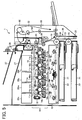
- Figure 5 is a schematic structure of a main body of the image forming apparatus of Figure 4;
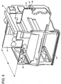
- Figure 6 is a schematic structure of a frame structure included in the image forming apparatus;
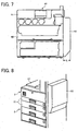
- Figure 7 is a front view of the schematic structure of Figure 6;
- Figure 8 is a perspective view of the main body when a duplex print unit is closed;
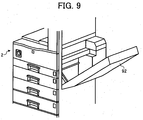
- Figure 9 is a perspective view of the main body when the duplex print unit is opened;
- Figure 10 is a perspective view with an extended portion of a frame plate supporting a drive motor; and
- Figure 11 is an enlarged view of a portion of the duplex print unit.
- In describing preferred embodiments illustrated in the drawings, specific terminology is employed for the sake of clarity. However, the disclosure of this patent specification is not intended to be limited to the specific terminology so selected and it is to be understood that each specific element includes all technical equivalents that operate in a similar manner.
- Referring now to the drawings, wherein like reference numerals designate identical or corresponding parts throughout the several views, preferred embodiments of the present invention are described.
- Referring to Figure 4, a schematic structure of an image forming apparatus 1 according to an embodiment of the present invention is described.
- The image forming apparatus 1 is a tandem-type electrophotographic image forming apparatus which includes an indirect transfer system.
- The image forming apparatus 1 includes a
main body 2 thereof, animage scanning mechanism 3, an automatic document feeder (ADF) 4, and an optionalsheet feeding mechanism 5. - The
main body 2 of the image forming apparatus 1 includes twosheet feeding cassettes 21, andsheet discharging trays 27. Thesheet feeding cassettes 21 serve as a standard sheet feeding mechanism and are loaded with respective stacks of sheets of particular size including a recording sheet (not shown). Thesheet discharging trays 27 receives the recording sheet discharged or conveyed from themain body 2. Detailed inner structure of themain body 2 will be described later, referring to Figure 5. - A
duplex print unit 92 is mounted as an open and close unit on the right side of themain body 2 of the image forming apparatus 1 in Figure 4. Details of theduplex print unit 92 will be described later, referring to Figure 5. - The
image scanning mechanism 3 is arranged above themain body 2, and includes a contact glass (not shown), and aconsole display 90. The contact glass is mounted on the top of theimage scanning mechanism 3. Theconsole display 90 is mounted at the front portion of the image forming apparatus 1, substantially horizontally extending toward a front side where a user generally stands to use the image forming apparatus 1. - The
ADF 4 is arranged above theimage scanning mechanism 3. TheADF 4 is disposed to be capable of vertically and rotatably opening and closing about a horizontal shaft (serving as a supporting shaft) at a rear end thereof. - The optional
sheet feeding mechanism 5 serves as an optional unit and supports themain body 2, theimage scanning mechanism 3, and theADF 4 thereon. The opticalsheet feeding mechanism 5 includes twosheet feeding cassettes 91. Thesheet feeding cassettes 91 are vertically disposed to each other, and are slidable to open at the front side of the opticalsheet feeding mechanism 5 for loading and unloading recording sheets. - Referring to Figure 5, a structure of an inner mechanism of the
main body 2 of the image forming apparatus 1 shown in Figure 4 is described. - The image forming apparatus 1 further includes
image forming mechanism 32, anoptical writing unit 13,toner replenishing units sheet conveying part 36. - The
image forming mechanism 32 includesimage forming units 10c, 10m, 10y, and 10bk, anintermediate transfer member 15,primary transfer units secondary transfer unit 25,primary cleaning units secondary cleaning unit 18. - The
image forming units 10c, 10m, 10y, and 10bk are separately arranged at positions having horizontal heights or elevations forming a tandem-type image forming mechanism to form cyan images, magenta images, yellow images, and black images, respectively. Theimage forming units 10c, 10m, 10y, and 10bk respectively have drum-shapedimage bearing members units units 14c, 14m, 14y, and 14bk. The chargingunits units 14c, 14m, 14y, and 14bk are arranged around the respectiveimage bearing members image forming units 10c, 10m, 10y, and 10bk. - The
image bearing members - The charging
units 14c, 14m, 14y, and 14bk uniformly charge respective surfaces of the correspondingimage bearing members - The
optical writing unit 13 emits laser light beams Lc, Lm, Ly, and Lbk to irradiate respective surfaces of the correspondingimage bearing members - The developing
units 14c, 14m, 14y, and 14bk supply respective color toners to the respective surfaces of theimage bearing members image bearing members units 14c, 14m, 14y, and 14bk contain the different colored toners supplied by thetoner replenishing units - The single toner images formed on the respective surfaces of the
image bearing members intermediate transfer member 15 to form an overlaid full color toner image. - The
intermediate transfer member 15 is disposed above theimage forming units 10c, 10m, 10y, and 10bk. Theintermediate transfer member 15 is an endless belt rotating in a counterclockwise direction in Figure 5. Theintermediate transfer member 15 is held in contact with theprimary transferring units intermediate transfer member 15 to face the respectiveimage bearing members image forming units 10c, 10m, 10y, and 10bk, respectively. - The
primary transfer units image bearing members intermediate transfer member 15 that is previously charged. By transferring the respective single toner images, the overlaid full color toner image is formed on the surface of theintermediate transfer member 15. - While the
image forming mechanism 32 is forming the above-described color toner image, a recording medium such as a recording sheet is fed from one of thesheet feeding cassettes 21 in the standard sheet feeding mechanism of the image forming apparatus 1. - The standard sheet feeding mechanism including the
sheet conveying part 36 includes thesheet feeding cassettes 21, the recording medium orrecording sheet 22,sheet feeding rollers 20, a recordingsheet conveying path 23, and a pair ofregistration rollers 24. - The image forming apparatus 1 selects one of the
sheet feeding cassettes 21 of themain body 2 and thesheet feeding cassettes 91 of the optionalsheet feeding mechanism 5 to feed therecording medium 22 therefrom. The image forming apparatus 1 selectively rotates thesheet feeding roller 20 at a predetermined timing to feed therecording sheet 22, and conveys therecording sheet 22 through the recordingsheet conveying path 23 toward the pair ofregistration rollers 24. The recordingsheet conveying path 23 passes therecording sheet 22 therethough. The pair ofregistration rollers 24 supplies therecording sheet 22 in synchronization with respective the movement of theimage forming mechanism 32 so that thesecondary transfer unit 25 may transfer the full color image formed on theintermediate transfer member 15 onto a proper position of therecording sheet 22. The full color toner image on therecording sheet 22 is then conveyed upward through the recordingsheet conveying path 23 to be fixed by a fixingunit 30 through application of heat and pressure. Therecording sheet 22 having the fixed full color image is conveyed bysheet discharging rollers 26 and is discharged to one of thesheet discharging trays 27 arranged on the top portion of themain body 2 of the image forming apparatus 1. - After the respective single toner images formed on the respective surfaces of the
image bearing members intermediate transfer member 15, respective color toners remaining on theimage bearing members primary cleaning units - After the full color toner image is transferred onto the
recording sheet 22, residual toner on theintermediate transfer member 15 is removed by thesecondary cleaning unit 18. - When a duplex print operation is performed to form different images on respective sides of the
recording sheets 22 in the image forming apparatus 1 of Figure 5, therecording sheet 22 may pass through theduplex print unit 92. Theduplex print unit 92 includes aswitchback path 93, a reversesheet conveying path 94, a recordingmedium conveying system 95, and ahorizontal shaft 35. - After the fixing
unit 30 fixes therecording sheet 22 having an image on one side of therecording sheet 22, therecording sheet 22 is conveyed toward apath selector 33. Thepath selector 33 may be switched to allow therecording sheet 22 to go to .theduplex print unit 92. When theduplex print unit 92 receives therecording sheet 22, theswitchback path 93 reverses therecording sheet 22 to the different surface side orientation. The reversedrecording sheet 22 is then conveyed through the reversesheet conveying path 94 to a secondary transfer area formed between theintermediate transfer member 15 and thesecondary transfer unit 25 of themain body 2 so that a next full color toner image can be transferred onto the rear surface of therecording sheet 22. Then, therecording sheet 22 having full color toner images printed on the front and rear sides is conveyed via the fixingunit 30 to one of thesheet discharging trays 27 by the correspondingsheet discharging rollers 26. - Referring to Figures 6 and 7, a
schematic frame structure 44 of the image forming apparatus 1 is described. - A pair of frame plates or front and
rear frame plates main body 2 in the image forming apparatus 1. The front andrear frame plates - The
front frame plate 40 is disposed at the front side of the image forming apparatus 1, and therear frame plate 41 is disposed at a rear side of the image forming apparatus 1. As previously described, the front side is the nearest side from where a user or operator stands when the user operates the image forming apparatus 1. Conversely, the rear side is the farthest side from the user. The front andrear frame plates bottom plate 42 and anintermediate plate 43 to form theframe structure 44 as shown in Figure 6. The front andrear frame plates image forming mechanism 32 including theimage forming units 10c, 10m, 10y, and 10bk, theintermediate transfer member 15, theprimary transfer units secondary cleaning unit 18, thesecondary transfer unit 25 and the like so that theimage forming mechanism 32 may be mounted to theframe structure 44. - The
image forming mechanism 32 of Figure 6 employs an indirect transfer method with the tandem type electrophotographic image forming apparatus. However, the image forming mechanism is not limited to be used in the above-described image forming apparatus. For example, an embodiment of the present invention can be an image forming apparatus using a direct transfer method or a single image bearing member. - As shown in Figure 7, the
rear frame plate 41 has a portion horizontally extended to the right side by a length L, compared with thefront frame plate 40. The portion extended by the length L is defined as an extended portion 45 (shown in Figures 6 and 7) of therear frame plate 41. - The
rear frame plate 41 may supportdrive motors drive motors extended portion 45 protrudes at the right side of themain body 2 of the image forming apparatus 1 and forms an area with the length L and the width W. Theduplex print unit 92 is rotatably mounted within the area of the extendedportion 45 with respect to themain body 2 of the image forming apparatus 1, as shown in Figure 7. - Referring to Figures 8 and 9, the detailed structure of the
duplex print unit 92 is described. - The
duplex print unit 92 may pivotably open and close in a vertical manner around thehorizontal shaft 35 as shown in Figure 8. - Referring back to Figure 5, the
duplex print unit 92 is mounted in a proximate outside of the recordingsheet conveying path 23 included in themain body 2 of the image forming apparatus 1. When a paper jam occurs, a jammed paper stuck in the recordingsheet conveying path 23 may easily be removed by opening theduplex print unit 92 serving as an open and close unit. Theduplex print unit 92 may be opened as shown in Figure 9. Opening theduplex print unit 92 may widely expose thesheet conveying part 36 of themain body 2 of the image forming apparatus 1, which allows the user to easily remove the jammed paper from the recordingsheet conveying path 23. - Referring now to Figure 10, the
extended portion 45 of therear frame plate 41 is described. - As described above, the
duplex print unit 92 includes the recordingmedium conveying system 95 for reversing therecording sheet 22 so that therecording sheet 22 may repeatedly be supplied to theimage forming mechanism 32. Theextended portion 45 of therear frame plate 41 may support a portion of a drive controlling mechanism that is configured to control the recordingmedium conveying system 95 to drive. That is, the portion of the drive controlling mechanism may separately be mounted on theextended portion 45 of therear frame plate 41. The drive controlling mechanism includes thedrive motor 46, a solenoid, and a detecting member. Thedrive motor 46 drives a conveying member such as rollers and belts included in the recordingmedium conveying system 95. The solenoid switches a switching member such as thepath selector 33 for switching or selecting the direction of the recording medium. The detecting member detects therecording sheet 22 during the travel of therecording sheet 22. Thedrive motor 47 in Figure 10 drives the pair ofregistration rollers 24. Aduct outlet 48 is disposed at the upper portion of the extendedportion 45 in an outwardly extending manner. - Operations of removing a jammed paper are described below.
- When the user wants to remove the jammed paper from the image forming apparatus 1 with the
drive motor 46 separately mounted on theextended portion 45, theduplex print unit 92 serving as the open and close unit is rotated around thehorizontal shaft 35 to be opened outwardly as shown in Figure 9. The user may insert his or her hand(s) inside themain body 2 of the image forming apparatus 1 from the front side of the image forming apparatus 1, remove the jammed paper stuck in the recordingsheet conveying path 23, and close theduplex print unit 92 as shown in Figure 8. - Referring to Figure 11, a detailed structure of the
duplex print unit 92 is described. - As shown in Figure 11, the
duplex print unit 92 includes a driveforce transmission unit 96 mounted on theextended portion 45 of therear frame plate 41. The driveforce transmission unit 96 includes a plurality ofgears 97. When theduplex print unit 92 is closed, a motor gear of thedrive motor 46 supported by the extendedportion 45 may engage with one of the plurality ofgears 97 of the driveforce transmission unit 96 so that drive force of thedrive motor 46 may be transmitted to the conveying member such as the rollers and belts of the recordingmedium conveying system 95 to rotate the conveying member and convey therecording sheet 22. When theduplex print unit 92 is opened, the motor gear of thedrive motor 46 may be disengaged from one of the plurality of gears of the driveforce transmission unit 96. - As described above, the
drive motor 46 is separated from theduplex print unit 92 and is mounted on therear frame plate 41 of themain body 2 of the image forming apparatus 1, and theduplex print unit 92 without thedrive motor 46 thereon is opened and closed with respect to themain body 2 of the image forming apparatus 1. By providing thedrive motor 46 separately from theduplex print unit 92, the structure of theduplex print unit 92 may not be complicated or increase the cost. Theduplex print unit 92 having the above-described structure may be made smaller, thereby increasing operability of opening and closing theduplex print unit 92 when the paper jam occurs. Further, theduplex print unit 92 may not be connected to harnesses, thereby increasing reliability of the image forming apparatus 1. - In the exemplary embodiment, the front and
rear frame plate duplex print unit 92 serving as the open and close unit is disposed at the right-hand side of themain body 2 of the image forming apparatus 1. As an alternative, a pair of frame plates may be disposed opposite to each other at the right-hand and left-hand sides of the image forming apparatus 1, and an open and close unit may be disposed at the front or rear side of themain body 2 of the image forming apparatus 1. Further, thehorizontal shaft 35 is not limited to rotate theduplex print unit 92. For example, theduplex print unit 92 may be rotated around a vertical shaft. - When the vertical shaft is disposed at the right-hand or left-hand side of the
main body 2 of the image forming apparatus 1, theduplex print unit 92 may open toward the front and/or rear side of the image forming apparatus 1. When the vertical shaft is disposed at the front or rear side of themain body 2 of the image forming apparatus 1, theduplex print unit 92 may open toward the right-hand and/or left-hand side of the image forming apparatus 1. - By forming the
front frame plate 40 smaller than therear frame plate 41, the paper jam may easily be solved. That is, when theduplex print unit 92 is opened, the user may smoothly insert his or her hand(s) from the front side of the image forming apparatus 1 to easily remove the jammed paper. - By providing the
extended portion 45 for therear frame plate 41 of the image forming apparatus 1, theduplex print unit 92 may be disposed at theextended portion 45. That is, when theduplex print unit 92 is opened, the inside of the image forming apparatus 1 may be widely exposed in the vicinity of the close outside of the image forming apparatus 1, and the user may insert his or her hand(s) from the front side of the image forming apparatus 1 more smoothly to remove the jammed paper more easily. - In the exemplary embodiment described above, the open and close unit, i.e., the
duplex print unit 92 opens and closes for performing the paper jam operation. However, the open and close unit is not limited to the above-described duplex print unit and/or not limited for performing the paper jam operation. The embodiment of the present invention can be an open and close unit to be opened and closed for the purpose of replacement of parts or consumables, repair, and/or maintenance. - When recording images on the front and rear side of the
recording sheet 22 by using theduplex print unit 92, therecording sheet 22 having an image on one side is conveyed to theduplex print unit 92 to be reversed such that therecording sheet 22 may be supplied to theimage forming mechanism 32 again. - When the paper jam operation is performed, the portion of the drive controlling mechanism for controlling the recording
medium conveying system 95 may be supported by the extendedportion 45 separately from theduplex print unit 92, and theduplex print unit 92 may be opened and closed with respect to themain body 2 of the image forming apparatus 1. - By simply providing the portion of the drive controlling mechanism separately from the
duplex print unit 92 that is relatively heavy, theduplex print unit 92 may not complicated in the structure and not increase the cost. Further, theduplex print unit 92 may be made smaller or more compact to increase operability of opening and closing in performing the paper jam operation. Furthermore, theduplex print unit 92 may increase reliability such that the open and close unit may not be connected to the harnesses. - When the paper jam operation is performed, the
duplex print unit 92 is opened to release the recordingsheet conveying path 23 disposed right inside thereof. Since the recordingsheet conveying path 23 is widely exposed, the user can easily remove the jammed paper stuck in the recordingsheet conveying path 23. - The front and
rear frame plates frame structure 44 including a resin material. Compared with a frame structure including a metal material, the above-describedframe structure 44 may decrease the weight of themain body 2 of the image forming apparatus 1, resulting in reduction of costs. Further, the front andrear frame plates - The above-described embodiments show the open and close unit, i.e., the
duplex print unit 92 rotating around the horizontal or vertical shaft serving as a supporting point so that theduplex print unit 92 opens and closes with respect to themain body 2 of the image forming apparatus 1. Alternatively, the open and close unit may be opened and closed by detaching from the image forming apparatus 1. Furthermore, the open and close unit may be opened and closed by sliding or horizontally moving with respect to the image forming apparatus 1. Even in these cases, by supporting thedrive motor 46 at theextended portion 45, operability in opening and closing the open and close unit may be improved. - The above-described embodiments are illustrative, and numerous additional modifications and variations are possible in light of the above teachings. For example, elements and/or features of different illustrative and exemplary embodiments herein may be combined with each other and/or substituted for each other within the scope of this disclosure and appended claims. It is therefore to be understood that within the scope of the appended claims, the disclosure of this patent specification may be practiced otherwise than as specifically described herein.
Claims (13)
- An image forming apparatus, comprising:first and second frame plates oppositely disposed and spaced apart by a predetermined width from each other, the second frame plate comprising an extended portion horizontally extending by a predetermined length compared with the first frame plate;an open and close unit disposed within an area of the extended portion between the first and second frame plates and configured to freely open and close with respect to the image forming apparatus, the open and close unit comprising a recording medium conveying system configured to convey a recording medium; anda drive controlling mechanism configured to control the recording medium conveying system,wherein the extended portion supports at least a portion of the drive controlling mechanism so as to be separately mounted from the open and close unit on a side of the image forming apparatus.
- The image forming apparatus according to claim 1, wherein:the first frame plate comprises a front frame plate disposed at a front side of the image forming apparatus; and the second frame plate comprises a rear frame plate disposed at a rear side of the image forming apparatus, the rear frame plate comprising the extended portion horizontally extending by the predetermined length compared with the front frame plate.
- The image forming apparatus according to claim 2,
wherein:the extended portion of the rear frame plate is horizontally extended to mount the open and close unit with respect to the image forming apparatus. - The image forming apparatus according to claim 3,
wherein:the recording medium conveying system comprises a conveying member configured to convey the recording medium, and
the portion of the drive controlling mechanism includes a driving source configured to rotatably drive the conveying member. - The image forming apparatus according to claim 3, wherein:the recording medium conveying system comprises a switching member configured to switch a direction of travel of the recording medium, and
the portion of the drive controlling mechanism includes a solenoid configured to drive the switching member. - The image forming apparatus according to claim 3, wherein:the portion of the drive controlling mechanism includes a detecting member configured to detect the recording medium conveyed to the recording medium conveying system.
- The image forming apparatus according to on of claims 1 to 6, wherein:the open and close unit includes a duplex print unit.
- The image forming apparatus according to one of claims 1 to 7, further comprising a recording medium conveying path configured to pass the recording medium therethrough,
wherein the open and close unit is disposed at a point proximate to the recording medium conveying path. - The image forming apparatus according to claim 8, wherein:the open and close unit is rotatably disposed on a shaft.
- The image forming apparatus according to one of claims 1 to 9, further comprising a sheet feeding cassette including a sheet conveying part,
wherein the sheet conveying part is exposed to an outside of the image forming apparatus when the open and close unit is opened. - The image forming apparatus according to one claims 1 to 10, wherein:the first and second frame plates are formed of a resin material molded in one piece.
- A method of mounting an open and close unit on an image forming apparatus, comprising:disposing first and second frame plates oppositely spaced apart by a predetermined width from each other, the second frame plate comprising an extended portion horizontally extending by a predetermined length compared with the first frame plate;mounting an open and close unit within an area of the extended portion between the first and second frame plates and configured to freely open and close with respect to the image forming apparatus, the open and close unit comprising a recording medium conveying system configured to convey arecording medium; andmounting at least a portion of a drive controllingmechanism configured to control the recording medium conveying system so that the portion of the drive controlling mechanism is supported separately from the open and close unit.
- The method according to claim 12, further comprising:disposing the open and close unit at a point proximate to a recording medium conveying path of the image forming apparatus.
Applications Claiming Priority (2)
| Application Number | Priority Date | Filing Date | Title |
|---|---|---|---|
| JP2004305141 | 2004-10-20 | ||
| JP2005179586A JP4737603B2 (en) | 2004-10-20 | 2005-06-20 | Image forming apparatus |
Publications (2)
| Publication Number | Publication Date |
|---|---|
| EP1650613A1 true EP1650613A1 (en) | 2006-04-26 |
| EP1650613B1 EP1650613B1 (en) | 2009-02-18 |
Family
ID=35395883
Family Applications (1)
| Application Number | Title | Priority Date | Filing Date |
|---|---|---|---|
| EP05022877A Expired - Lifetime EP1650613B1 (en) | 2004-10-20 | 2005-10-20 | An image forming apparatus mounted with an open and close unit |
Country Status (4)
| Country | Link |
|---|---|
| US (1) | US7317885B2 (en) |
| EP (1) | EP1650613B1 (en) |
| JP (1) | JP4737603B2 (en) |
| DE (1) | DE602005012771D1 (en) |
Families Citing this family (2)
| Publication number | Priority date | Publication date | Assignee | Title |
|---|---|---|---|---|
| JP5354062B2 (en) * | 2012-05-28 | 2013-11-27 | 株式会社リコー | Image forming apparatus |
| JP6260760B2 (en) * | 2013-03-29 | 2018-01-17 | セイコーエプソン株式会社 | Recording device |
Citations (3)
| Publication number | Priority date | Publication date | Assignee | Title |
|---|---|---|---|---|
| US5839032A (en) * | 1996-03-08 | 1998-11-17 | Ricoh Company, Ltd. | Image forming apparatus having selectably controlled sheet discharge paths |
| JPH11314780A (en) * | 1998-05-07 | 1999-11-16 | Canon Inc | Paper feeder and image forming apparatus having the same |
| US20020114634A1 (en) * | 2001-02-19 | 2002-08-22 | Samsung Electronics Co., Ltd. | Image forming apparatus |
Family Cites Families (24)
| Publication number | Priority date | Publication date | Assignee | Title |
|---|---|---|---|---|
| US33393A (en) * | 1861-10-01 | Improvement in envelopes for cartridges | ||
| US89315A (en) * | 1869-04-27 | Improved dress-protector for carriage-wheels | ||
| US182048A (en) * | 1876-09-12 | Improvement in vehicle-wheels | ||
| US4866482A (en) * | 1986-10-24 | 1989-09-12 | Ricoh Company, Ltd. | Image forming device for electrostatic recording apparatus having a slidable replacement holding case |
| JP3518815B2 (en) * | 1994-05-10 | 2004-04-12 | 株式会社リコー | Image forming device |
| JPH0943929A (en) * | 1995-05-19 | 1997-02-14 | Matsushita Electric Ind Co Ltd | Electrophotographic copying machine |
| JPH08328451A (en) | 1995-05-29 | 1996-12-13 | Canon Inc | Image forming device |
| JP3358409B2 (en) * | 1995-11-13 | 2002-12-16 | ミノルタ株式会社 | Image forming device |
| JPH10161507A (en) * | 1996-12-02 | 1998-06-19 | Canon Inc | Image forming device |
| US6215970B1 (en) * | 1999-01-13 | 2001-04-10 | Ricoh Company, Ltd. | Duplex unit with recess for retracting manual sheet feeding tray and image forming apparatus using the same duplex unit |
| JP2000323859A (en) * | 1999-05-13 | 2000-11-24 | Ricoh Co Ltd | Bracket member |
| JP3738161B2 (en) * | 1999-11-22 | 2006-01-25 | 京セラミタ株式会社 | Image forming apparatus |
| JP2001312188A (en) | 2000-02-24 | 2001-11-09 | Ricoh Co Ltd | Exhaust device and image forming apparatus including the same |
| JP2001290313A (en) * | 2000-04-05 | 2001-10-19 | Matsushita Graphic Communication Systems Inc | Image recorder and facsimile machine equipped with the same |
| JP2003233287A (en) * | 2001-12-07 | 2003-08-22 | Ricoh Co Ltd | Image forming apparatus and image forming method |
| JP2003302800A (en) | 2002-04-12 | 2003-10-24 | Ricoh Co Ltd | Drive transmission device for printing device and printing device using the same |
| JP2003316087A (en) * | 2002-04-26 | 2003-11-06 | Ricoh Co Ltd | Image forming device |
| JP2004138683A (en) * | 2002-10-15 | 2004-05-13 | Canon Inc | Image forming device |
| JP2004191550A (en) * | 2002-12-10 | 2004-07-08 | Murata Mach Ltd | Image forming apparatus |
| JP4050145B2 (en) | 2002-12-26 | 2008-02-20 | 株式会社リコー | Packing method and packing tool used therefor |
| JP3870919B2 (en) * | 2003-03-20 | 2007-01-24 | ブラザー工業株式会社 | Image forming apparatus |
| KR100547129B1 (en) * | 2003-07-04 | 2006-01-26 | 삼성전자주식회사 | Electrophotographic printing press |
| ES2271921T3 (en) | 2003-09-18 | 2007-04-16 | Ricoh Company, Ltd. | PREVENT THE ENTRY OF TONER POWDER AND DUST DISPERSED IN AN OPTICAL WRITING DEVICE. |
| JP3919760B2 (en) * | 2004-03-09 | 2007-05-30 | 富士ゼロックス株式会社 | Image forming apparatus |
-
2005
- 2005-06-20 JP JP2005179586A patent/JP4737603B2/en not_active Expired - Fee Related
- 2005-10-20 EP EP05022877A patent/EP1650613B1/en not_active Expired - Lifetime
- 2005-10-20 DE DE602005012771T patent/DE602005012771D1/en not_active Expired - Lifetime
- 2005-10-20 US US11/253,664 patent/US7317885B2/en not_active Expired - Fee Related
Patent Citations (3)
| Publication number | Priority date | Publication date | Assignee | Title |
|---|---|---|---|---|
| US5839032A (en) * | 1996-03-08 | 1998-11-17 | Ricoh Company, Ltd. | Image forming apparatus having selectably controlled sheet discharge paths |
| JPH11314780A (en) * | 1998-05-07 | 1999-11-16 | Canon Inc | Paper feeder and image forming apparatus having the same |
| US20020114634A1 (en) * | 2001-02-19 | 2002-08-22 | Samsung Electronics Co., Ltd. | Image forming apparatus |
Non-Patent Citations (1)
| Title |
|---|
| PATENT ABSTRACTS OF JAPAN vol. 2000, no. 02 29 February 2000 (2000-02-29) * |
Also Published As
| Publication number | Publication date |
|---|---|
| US7317885B2 (en) | 2008-01-08 |
| DE602005012771D1 (en) | 2009-04-02 |
| EP1650613B1 (en) | 2009-02-18 |
| JP2006146142A (en) | 2006-06-08 |
| JP4737603B2 (en) | 2011-08-03 |
| US20060093396A1 (en) | 2006-05-04 |
Similar Documents
| Publication | Publication Date | Title |
|---|---|---|
| US8583006B2 (en) | Electrophotographic image forming apparatus and process cartridge with electrical contacts that urge developer roller to photosensitive drum | |
| US8526841B2 (en) | Process cartridge and electrophotographic image forming apparatus | |
| JP5135371B2 (en) | Image forming apparatus and relay unit | |
| US20110116832A1 (en) | Process cartridge and electrophotographic image forming apparatus | |
| JP4750506B2 (en) | Image forming apparatus | |
| US20070269233A1 (en) | Image forming apparatus | |
| EP1865383B1 (en) | Image forming system and sheet feed apparatus having enhanced functionality | |
| US20120193869A1 (en) | Sheet feeder and image forming apparatus with the same | |
| JP2014001019A (en) | Sheet conveyance device and image forming apparatus | |
| US8254809B2 (en) | Electrophotographic image forming apparatus | |
| US12487559B2 (en) | Image forming apparatus having improved mountability of a cartridge while conserving space | |
| US20080150227A1 (en) | Image forming apparatus | |
| JP6210693B2 (en) | Image forming apparatus | |
| JP2006171534A (en) | Image forming apparatus | |
| EP1650613B1 (en) | An image forming apparatus mounted with an open and close unit | |
| JP5087700B2 (en) | Paper feeding device and image forming system | |
| JP5470892B2 (en) | Image forming apparatus | |
| JP2011022331A (en) | Image forming apparatus | |
| JP4547217B2 (en) | Image forming apparatus | |
| JP2006163381A (en) | Image forming apparatus | |
| JP2012017201A (en) | Image processor | |
| JP2025074927A (en) | Image forming device | |
| JP2005308883A (en) | Image forming apparatus | |
| JP2023027453A (en) | Image formation device | |
| JP2022152383A (en) | Manual paper-feeding device, and image forming apparatus |
Legal Events
| Date | Code | Title | Description |
|---|---|---|---|
| PUAI | Public reference made under article 153(3) epc to a published international application that has entered the european phase |
Free format text: ORIGINAL CODE: 0009012 |
|
| AK | Designated contracting states |
Kind code of ref document: A1 Designated state(s): AT BE BG CH CY CZ DE DK EE ES FI FR GB GR HU IE IS IT LI LT LU LV MC NL PL PT RO SE SI SK TR |
|
| AX | Request for extension of the european patent |
Extension state: AL BA HR MK YU |
|
| 17P | Request for examination filed |
Effective date: 20060531 |
|
| 17Q | First examination report despatched |
Effective date: 20060628 |
|
| AKX | Designation fees paid |
Designated state(s): DE FR GB |
|
| GRAP | Despatch of communication of intention to grant a patent |
Free format text: ORIGINAL CODE: EPIDOSNIGR1 |
|
| GRAS | Grant fee paid |
Free format text: ORIGINAL CODE: EPIDOSNIGR3 |
|
| GRAA | (expected) grant |
Free format text: ORIGINAL CODE: 0009210 |
|
| AK | Designated contracting states |
Kind code of ref document: B1 Designated state(s): DE FR GB |
|
| REG | Reference to a national code |
Ref country code: GB Ref legal event code: FG4D |
|
| REF | Corresponds to: |
Ref document number: 602005012771 Country of ref document: DE Date of ref document: 20090402 Kind code of ref document: P |
|
| PLBE | No opposition filed within time limit |
Free format text: ORIGINAL CODE: 0009261 |
|
| STAA | Information on the status of an ep patent application or granted ep patent |
Free format text: STATUS: NO OPPOSITION FILED WITHIN TIME LIMIT |
|
| 26N | No opposition filed |
Effective date: 20091119 |
|
| REG | Reference to a national code |
Ref country code: FR Ref legal event code: PLFP Year of fee payment: 11 |
|
| REG | Reference to a national code |
Ref country code: FR Ref legal event code: PLFP Year of fee payment: 12 |
|
| PGFP | Annual fee paid to national office [announced via postgrant information from national office to epo] |
Ref country code: GB Payment date: 20161020 Year of fee payment: 12 Ref country code: FR Payment date: 20161020 Year of fee payment: 12 Ref country code: DE Payment date: 20161020 Year of fee payment: 12 |
|
| REG | Reference to a national code |
Ref country code: DE Ref legal event code: R119 Ref document number: 602005012771 Country of ref document: DE |
|
| GBPC | Gb: european patent ceased through non-payment of renewal fee |
Effective date: 20171020 |
|
| REG | Reference to a national code |
Ref country code: FR Ref legal event code: ST Effective date: 20180629 |
|
| PG25 | Lapsed in a contracting state [announced via postgrant information from national office to epo] |
Ref country code: DE Free format text: LAPSE BECAUSE OF NON-PAYMENT OF DUE FEES Effective date: 20180501 Ref country code: GB Free format text: LAPSE BECAUSE OF NON-PAYMENT OF DUE FEES Effective date: 20171020 |
|
| PG25 | Lapsed in a contracting state [announced via postgrant information from national office to epo] |
Ref country code: FR Free format text: LAPSE BECAUSE OF NON-PAYMENT OF DUE FEES Effective date: 20171031 |