EP1650472A2 - Apparatus and method for controlling rubber flow in positive drive belts - Google Patents
Apparatus and method for controlling rubber flow in positive drive belts Download PDFInfo
- Publication number
- EP1650472A2 EP1650472A2 EP05109443A EP05109443A EP1650472A2 EP 1650472 A2 EP1650472 A2 EP 1650472A2 EP 05109443 A EP05109443 A EP 05109443A EP 05109443 A EP05109443 A EP 05109443A EP 1650472 A2 EP1650472 A2 EP 1650472A2
- Authority
- EP
- European Patent Office
- Prior art keywords
- compound
- section
- positive drive
- belt
- drive belt
- Prior art date
- Legal status (The legal status is an assumption and is not a legal conclusion. Google has not performed a legal analysis and makes no representation as to the accuracy of the status listed.)
- Withdrawn
Links
- 238000000034 method Methods 0.000 title claims description 13
- 229920001971 elastomer Polymers 0.000 title description 9
- 239000005060 rubber Substances 0.000 title description 7
- 150000001875 compounds Chemical class 0.000 claims abstract description 66
- 239000004744 fabric Substances 0.000 claims abstract description 27
- 230000004888 barrier function Effects 0.000 claims description 4
- 239000010410 layer Substances 0.000 claims 4
- 239000011247 coating layer Substances 0.000 claims 1
- WZZBNLYBHUDSHF-DHLKQENFSA-N 1-[(3s,4s)-4-[8-(2-chloro-4-pyrimidin-2-yloxyphenyl)-7-fluoro-2-methylimidazo[4,5-c]quinolin-1-yl]-3-fluoropiperidin-1-yl]-2-hydroxyethanone Chemical compound CC1=NC2=CN=C3C=C(F)C(C=4C(=CC(OC=5N=CC=CN=5)=CC=4)Cl)=CC3=C2N1[C@H]1CCN(C(=O)CO)C[C@@H]1F WZZBNLYBHUDSHF-DHLKQENFSA-N 0.000 description 6
- 239000004677 Nylon Substances 0.000 description 6
- 229920001778 nylon Polymers 0.000 description 6
- OPFJDXRVMFKJJO-ZHHKINOHSA-N N-{[3-(2-benzamido-4-methyl-1,3-thiazol-5-yl)-pyrazol-5-yl]carbonyl}-G-dR-G-dD-dD-dD-NH2 Chemical compound S1C(C=2NN=C(C=2)C(=O)NCC(=O)N[C@H](CCCN=C(N)N)C(=O)NCC(=O)N[C@H](CC(O)=O)C(=O)N[C@H](CC(O)=O)C(=O)N[C@H](CC(O)=O)C(N)=O)=C(C)N=C1NC(=O)C1=CC=CC=C1 OPFJDXRVMFKJJO-ZHHKINOHSA-N 0.000 description 5
- 229940126086 compound 21 Drugs 0.000 description 5
- 239000000463 material Substances 0.000 description 5
- 229920000742 Cotton Polymers 0.000 description 4
- 229920000728 polyester Polymers 0.000 description 4
- 230000005540 biological transmission Effects 0.000 description 3
- 238000004519 manufacturing process Methods 0.000 description 3
- 239000000203 mixture Substances 0.000 description 3
- 229920000459 Nitrile rubber Polymers 0.000 description 2
- 229920003235 aromatic polyamide Polymers 0.000 description 2
- 229920001577 copolymer Polymers 0.000 description 2
- 239000000806 elastomer Substances 0.000 description 2
- 239000011159 matrix material Substances 0.000 description 2
- 229920002635 polyurethane Polymers 0.000 description 2
- 239000004814 polyurethane Substances 0.000 description 2
- 229920000049 Carbon (fiber) Polymers 0.000 description 1
- 229920002943 EPDM rubber Polymers 0.000 description 1
- 244000043261 Hevea brasiliensis Species 0.000 description 1
- 229920003189 Nylon 4,6 Polymers 0.000 description 1
- 229920002292 Nylon 6 Polymers 0.000 description 1
- 229920002302 Nylon 6,6 Polymers 0.000 description 1
- 239000005062 Polybutadiene Substances 0.000 description 1
- 229920000297 Rayon Polymers 0.000 description 1
- 229910000831 Steel Inorganic materials 0.000 description 1
- 238000005299 abrasion Methods 0.000 description 1
- 239000004760 aramid Substances 0.000 description 1
- 239000004917 carbon fiber Substances 0.000 description 1
- 125000003262 carboxylic acid ester group Chemical class [H]C([H])([*:2])OC(=O)C([H])([H])[*:1] 0.000 description 1
- 239000013536 elastomeric material Substances 0.000 description 1
- 229920006229 ethylene acrylic elastomer Polymers 0.000 description 1
- 239000011152 fibreglass Substances 0.000 description 1
- 229920002681 hypalon Polymers 0.000 description 1
- 239000000314 lubricant Substances 0.000 description 1
- VNWKTOKETHGBQD-UHFFFAOYSA-N methane Chemical compound C VNWKTOKETHGBQD-UHFFFAOYSA-N 0.000 description 1
- 238000000465 moulding Methods 0.000 description 1
- 229920003052 natural elastomer Polymers 0.000 description 1
- 229920001194 natural rubber Polymers 0.000 description 1
- 229920001084 poly(chloroprene) Polymers 0.000 description 1
- 229920002577 polybenzoxazole Polymers 0.000 description 1
- 229920002857 polybutadiene Polymers 0.000 description 1
- 229920001195 polyisoprene Polymers 0.000 description 1
- 230000002028 premature Effects 0.000 description 1
- 239000002964 rayon Substances 0.000 description 1
- 239000007787 solid Substances 0.000 description 1
- 239000010959 steel Substances 0.000 description 1
- 229920003048 styrene butadiene rubber Polymers 0.000 description 1
- 150000003751 zinc Chemical class 0.000 description 1
Images

Classifications
-
- F—MECHANICAL ENGINEERING; LIGHTING; HEATING; WEAPONS; BLASTING
- F16—ENGINEERING ELEMENTS AND UNITS; GENERAL MEASURES FOR PRODUCING AND MAINTAINING EFFECTIVE FUNCTIONING OF MACHINES OR INSTALLATIONS; THERMAL INSULATION IN GENERAL
- F16G—BELTS, CABLES, OR ROPES, PREDOMINANTLY USED FOR DRIVING PURPOSES; CHAINS; FITTINGS PREDOMINANTLY USED THEREFOR
- F16G1/00—Driving-belts
- F16G1/28—Driving-belts with a contact surface of special shape, e.g. toothed
Definitions
- This invention pertains to positive drive belts and to a method to manufacture such belts. More specifically, the present invention relates to a belt where fabric is placed between the tension portion of the belt and the teeth during the building stage to control flow of rubber during a curing cycle.
- the tooth compound does not have a high enough modulus of elasticity to carry the load applied to the belt and the teeth tear off the belt due to shear forces.
- the modulus of elasticity for the tension section compound is too high, resulting in belt cracks. This leads to tensile failure. Based upon the foregoing, a belt design is needed, which balances optimal tooth stiffness and flexibility in the tension section.
- the present invention provides a method for enabling a positive drive belt to be cured during a single curing cycle and yet be formed from two different rubber compounds, such that the rubber compounds do not intermix during curing.
- a positive drive belt also known as a power transmission belt, according to claim 1 is provided.
- Another object of the present invention is to provide a positive drive belt, wherein the tension section may be a first compound; the load carrying section may be a second compound, and the fabric layer may be adapted to prevent intermixing of the first compound and the second compound during an associated cure cycle.
- Another object of the present invention is to provide a positive drive belt, wherein the first compound has a first modulus of elasticity and the second compound has a second modulus of elasticity, the second modulus of elasticity being greater than the first modulus of elasticity.
- Another object of the present invention is to provide a positive drive belt, which may further comprise a coated fabric layer disposed on the cushion section.
- Another object of the present invention is to provide a positive drive belt, wherein the belt may have one driving surface.
- Another object of the present invention is to provide a positive drive belt, wherein the first modulus of elasticity may be 300 psi.
- Another object of the present invention is to provide a positive drive belt, wherein the second modulus of elasticity is 2000 psi.
- Another object of the present invention is to provide a positive drive belt, wherein the fabric layer may be 0.3-oz/square yard spun-bond Nylon.
- another object of the present invention is to provide a positive drive belt, wherein the cushion section may further comprise a plurality of cords disposed in the cushion section.
- Another object of the present invention is to provide a positive drive belt according to claim 7.
- Another object of the present invention is to provide a positive drive belt, wherein the barrier may be a fabric layer.
- another object of the present invention is to provide a positive drive belt, wherein the tooth section may further comprise a load bearing section and a cushion section.
- Another object of the present invention is to provide a positive drive belt, wherein the fabric layer may be bonded between the tension section and the load bearing section.
- Another object of the present invention is to provide a method for forming a positive drive belt according to claim 8.
- Another object of the present invention is to provide a method for forming a positive drive belt, wherein the step of simultaneously curing the first compound and the second compound may further comprise the step of curing a coated fabric layer to the second compound.
- One advantage of this invention is that it reduces premature belt failure by preventing intermixing of two rubber compounds.
- Another object of the present invention to provide a positive drive belt that is economical to manufacture.
- An endless positive drive belt structure or belt 10 of may be adapted to be used in associated sprockets in accordance with techniques known in the art.
- the belt 10 is particularly suited for use in automotive and industrial applications.
- the belt 10 comprises a tension section 20, and a tooth section 25.
- the tooth section 25 comprises a cushion section 28 and a load-carrying section 23.
- the load-carrying section 23 is disposed between the tension section 20 and cushion section 28.
- a load-carrying section 23 has load-carrying means in the form of load-carrying cords 26 or filaments which are suitably embedded in an elastomeric cushion or matrix in accordance with techniques which are well known in the art.
- the cords 26 or filaments may be made of any suitable material known and used in the art. Representative examples of such materials include aramids, fiberglass, nylon, polyester, cotton, steel, carbon fiber and polybenzoxazole.
- the belt 10 also has an inside ply or inner fabric layer 22 disposed between the tension section 20 and the load carrying section 23.
- the belt 10 has a series of spaced cogs or teeth 24 and alternating land portions 29 of the belt 10.
- the tension section 20 may be formed from a first compound 21. Further, load-carrying section 23 of the tooth section 25 may be formed from a second compound 30.
- the fabric layer 22 forms a barrier between the tension section 20 and the load carrying section 23 to prevent intermixing of the first compound 21 and the second compound 30 during a curing cycle.
- the cushion section 28 may also be formed from the second compound 30.
- the first compound 21 has a first modulus of elasticity, which may range from 100 to 1500 psi. Further, the second compound 30 has a second modulus of elasticity, which may range from 1000 to 4000 psi. In the present invention, in order to increase belt life by providing stiffer teeth 24 and a more flexible tension section 20, the second modulus of elasticity should be greater than the first modulus of elasticity.
- the fabric layer 22 may be made from a bi-directional, non-woven, woven or knitted fabric. Also, the fabric layer 22 may be frictioned, spread or coated with an elastomeric material which is selected to assure the layer is bonded to its associated section in a tenacious manner.
- the fabrics for use in the present invention are made of conventional materials including nylon (such as nylon 4,6, nylon 6,6 and nylon 6), cotton, polyester, cotton/polyester, nylon/polyester, cotton/nylon, LycraTM (segmented polyurethane), aramid, rayon, and the like.
- the fabric may be made of 0.1-2.0, and preferably 0.3-oz/square yard spun-bond Nylon.
- the belt 10 comprises a tension section 20, a cushion section 28, and a load-carrying section 23.
- the load-carrying section 23 has load-carrying means in the form of load-carrying cords 26 or filaments as previously described.
- the tension section 20 may be formed of the first compound 21 and the cushion section 28 and load-carrying section 23 may be formed of the second compound 30.
- the fabric layer 22 is disposed between the tension section 20 and the load-carrying section 23.
- the belt of the present invention also include those belts where the drive surface of the belt may be single V-grooved and multi-V-grooved.
- the rubber compositions for use in the tension section 20 and cushion section 28 should be different in order to increase belt life.
- using the first compound 21 in the tension section 20 and the second compound 30 in the tooth section 25 enables greater tooth stiffness in the tooth section 25 and greater flexibility in the tension section 20.
- elastomers which may be used in one or both of these sections include natural rubber, polychloroprene, acrylonitrile-butadiene copolymers (NBR), polyisoprene, zinc salts of unsaturated carboxylic acid ester grafted hydrogenated nitrile butadiene elastomers, styrene-butadiene rubbers, polybutadiene, EPDM, hydrogenated acrylonitrile-butadiene copolymers (HNBR), polyurethane, elastomers marketed under the VitonTM designation and ethylene-acrylic elastomers sold under the name VAMAC and blends thereof.
- natural rubber polychloroprene, acrylonitrile-butadiene copolymers (NBR), polyisoprene, zinc salts of unsaturated carboxylic acid ester grafted hydrogenated nitrile butadiene elastomers, styrene-butadiene rubbers, polybut
- the positive drive belt may be made from material chosen in accordance with sound engineering judgment, including, but not limited to hydrogenated nitrile rubber and chlorosulfonated polyethylene.
- solid lubricants have been added to the rubber compositions to improve the abrasion properties of the belt by reducing the coefficient of friction.
- a mold is provided to form the positive drive belt.
- the first compound and second compound are also provided.
- the fabric layer is disposed between the first compound and the second compound.
- the first compound and the second compound are simultaneously cured. Intermixing is prevented of the first compound and the second compound.
- the first compound forms the tension section of the belt.
- the second compound forms the tooth section of the belt.
- the belt is then removed from the mold. Further, a coated fabric layer may be cured on said second compound.
- belt samples were fabricated.
- a soft tan compound was used in the tension section and a rigid dark compound was used in the tooth section.
- One set of belts had the fabric layer disposed between the tension section and the tooth section.
- the soft tan compound intermixed with the rigid dark compound.
- the soft tan compound attempted to break through and intermix with the tooth section, but it was held back by the fabric layer.
Landscapes
- Engineering & Computer Science (AREA)
- General Engineering & Computer Science (AREA)
- Mechanical Engineering (AREA)
- Belt Conveyors (AREA)
- Structure Of Belt Conveyors (AREA)
- Heating, Cooling, Or Curing Plastics Or The Like In General (AREA)
Abstract
Description
- This invention pertains to positive drive belts and to a method to manufacture such belts. More specifically, the present invention relates to a belt where fabric is placed between the tension portion of the belt and the teeth during the building stage to control flow of rubber during a curing cycle.
- Development in both the automotive and industrial marketplace has resulted in more demanding requirements for power transmission belts. As such, power transmission belts, also known as positive drive belts, have been required to operate under higher loads and at higher tensions, while reducing belt width. Based on the foregoing, there are demands for a high quality belt capable of withstanding these severe applications.
- In order to meet the demands for positive drive belts, it is desirable to reduce the occurrence of belt failure. Two major modes of failure exist for positive drive belts. First, the tooth compound does not have a high enough modulus of elasticity to carry the load applied to the belt and the teeth tear off the belt due to shear forces. Second, the modulus of elasticity for the tension section compound is too high, resulting in belt cracks. This leads to tensile failure. Based upon the foregoing, a belt design is needed, which balances optimal tooth stiffness and flexibility in the tension section.
- In order to reach this balance, it is common to utilize different materials in the tooth and tension sections of the belt in order to provide greater flexibility in the tension section and greater stiffness in the tooth region. Ideally, a very rigid compound would be used for the teeth and a soft compound for the tension section. While this may be simple for other types of belts, it is difficult in positive drive belts because the tooth compound must flow around the cords during the molding process. As such, it is difficult to prevent intermixing of the two compounds in positive drive belts. Until now, the only method for accomplishing this is to preform the belt teeth and then assemble the cord on top of the preformed matrix. While this enables different compounds to be used for the teeth and tension sections, it has inherent problems. First, cord adhesion is poor since the compound does not have to flow completely around the cord during cure. Second, preforming teeth is expensive because it adds another processing step in the manufacturing process.
- The present invention provides a method for enabling a positive drive belt to be cured during a single curing cycle and yet be formed from two different rubber compounds, such that the rubber compounds do not intermix during curing. By reducing the occurrence of failure, positive drive belt life is optimized and overall costs are reduced by requiring fewer belt replacements.
- According to one aspect of the present invention, a positive drive belt, also known as a power transmission belt, according to claim 1 is provided.
- Another object of the present invention is to provide a positive drive belt, wherein the tension section may be a first compound; the load carrying section may be a second compound, and the fabric layer may be adapted to prevent intermixing of the first compound and the second compound during an associated cure cycle.
- Another object of the present invention is to provide a positive drive belt, wherein the first compound has a first modulus of elasticity and the second compound has a second modulus of elasticity, the second modulus of elasticity being greater than the first modulus of elasticity.
- Further, another object of the present invention is to provide a positive drive belt, which may further comprise a coated fabric layer disposed on the cushion section.
- Still yet, another object of the present invention is to provide a positive drive belt, wherein the belt may have one driving surface.
- Still, another object of the present invention is to provide a positive drive belt, wherein the first modulus of elasticity may be 300 psi.
- Further, another object of the present invention is to provide a positive drive belt, wherein the second modulus of elasticity is 2000 psi.
- Yet, another object of the present invention is to provide a positive drive belt, wherein the fabric layer may be 0.3-oz/square yard spun-bond Nylon.
- Further yet, another object of the present invention is to provide a positive drive belt, wherein the cushion section may further comprise a plurality of cords disposed in the cushion section.
- Another object of the present invention is to provide a positive drive belt according to claim 7.
- Further, another object of the present invention is to provide a positive drive belt, wherein the barrier may be a fabric layer.
- Further yet, another object of the present invention is to provide a positive drive belt, wherein the tooth section may further comprise a load bearing section and a cushion section.
- Yet, another object of the present invention is to provide a positive drive belt, wherein the fabric layer may be bonded between the tension section and the load bearing section.
- Another object of the present invention is to provide a method for forming a positive drive belt according to claim 8.
- Another object of the present invention is to provide a method for forming a positive drive belt, wherein the step of simultaneously curing the first compound and the second compound may further comprise the step of curing a coated fabric layer to the second compound.
- One advantage of this invention is that it reduces premature belt failure by preventing intermixing of two rubber compounds.
- Another object of the present invention to provide a positive drive belt that is economical to manufacture.
- The invention may take physical form in certain parts and arrangement of parts, a preferred embodiment of which will be described in detail in this specification and illustrated in the accompanying drawings which form a part hereof and wherein:
- FIGURE 1 is a perspective view of the present invention.
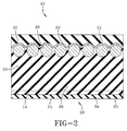
- FIGURE 2 is a side view of FIGURE 1.
- Referring now to the drawings wherein the showings are for purposes of illustrating a preferred embodiment of the invention. An endless positive drive belt structure or
belt 10 of may be adapted to be used in associated sprockets in accordance with techniques known in the art. Thebelt 10 is particularly suited for use in automotive and industrial applications. - With reference to FIGURE 1 the
belt 10 comprises atension section 20, and atooth section 25. Thetooth section 25 comprises acushion section 28 and a load-carryingsection 23. The load-carryingsection 23 is disposed between thetension section 20 andcushion section 28. A load-carryingsection 23 has load-carrying means in the form of load-carryingcords 26 or filaments which are suitably embedded in an elastomeric cushion or matrix in accordance with techniques which are well known in the art. Thecords 26 or filaments may be made of any suitable material known and used in the art. Representative examples of such materials include aramids, fiberglass, nylon, polyester, cotton, steel, carbon fiber and polybenzoxazole. With continuing reference to FIGURE 1, thebelt 10 also has an inside ply orinner fabric layer 22 disposed between thetension section 20 and theload carrying section 23. In the embodiment shown in FIGURE 1, thebelt 10 has a series of spaced cogs orteeth 24 and alternatingland portions 29 of thebelt 10. - With continuing reference to FIGURE 1, the
tension section 20 may be formed from afirst compound 21. Further, load-carryingsection 23 of thetooth section 25 may be formed from asecond compound 30. Thefabric layer 22 forms a barrier between thetension section 20 and theload carrying section 23 to prevent intermixing of thefirst compound 21 and thesecond compound 30 during a curing cycle. Thecushion section 28 may also be formed from thesecond compound 30. - The
first compound 21 has a first modulus of elasticity, which may range from 100 to 1500 psi. Further, thesecond compound 30 has a second modulus of elasticity, which may range from 1000 to 4000 psi. In the present invention, in order to increase belt life by providingstiffer teeth 24 and a moreflexible tension section 20, the second modulus of elasticity should be greater than the first modulus of elasticity. - The
fabric layer 22 may be made from a bi-directional, non-woven, woven or knitted fabric. Also, thefabric layer 22 may be frictioned, spread or coated with an elastomeric material which is selected to assure the layer is bonded to its associated section in a tenacious manner. The fabrics for use in the present invention are made of conventional materials including nylon (such as nylon 4,6, nylon 6,6 and nylon 6), cotton, polyester, cotton/polyester, nylon/polyester, cotton/nylon, Lycra™ (segmented polyurethane), aramid, rayon, and the like. Preferably, the fabric may be made of 0.1-2.0, and preferably 0.3-oz/square yard spun-bond Nylon. - With reference to FIGURE 2, another embodiment of the
positive drive belt 10 is shown, which is similar to that previously described. Thebelt 10 comprises atension section 20, acushion section 28, and a load-carryingsection 23. The load-carryingsection 23 has load-carrying means in the form of load-carryingcords 26 or filaments as previously described. Further, thetension section 20 may be formed of thefirst compound 21 and thecushion section 28 and load-carryingsection 23 may be formed of thesecond compound 30. Thefabric layer 22 is disposed between thetension section 20 and the load-carryingsection 23. - It is contemplated that the belt of the present invention also include those belts where the drive surface of the belt may be single V-grooved and multi-V-grooved.
- The rubber compositions for use in the
tension section 20 andcushion section 28 should be different in order to increase belt life. For example, with reference to FIGURE 1, using thefirst compound 21 in thetension section 20 and thesecond compound 30 in thetooth section 25 enables greater tooth stiffness in thetooth section 25 and greater flexibility in thetension section 20. Conventional elastomers which may be used in one or both of these sections include natural rubber, polychloroprene, acrylonitrile-butadiene copolymers (NBR), polyisoprene, zinc salts of unsaturated carboxylic acid ester grafted hydrogenated nitrile butadiene elastomers, styrene-butadiene rubbers, polybutadiene, EPDM, hydrogenated acrylonitrile-butadiene copolymers (HNBR), polyurethane, elastomers marketed under the Viton™ designation and ethylene-acrylic elastomers sold under the name VAMAC and blends thereof. - The positive drive belt may be made from material chosen in accordance with sound engineering judgment, including, but not limited to hydrogenated nitrile rubber and chlorosulfonated polyethylene. In addition, solid lubricants have been added to the rubber compositions to improve the abrasion properties of the belt by reducing the coefficient of friction.
- In order to form a positive drive belt, a mold is provided to form the positive drive belt. The first compound and second compound are also provided. The fabric layer is disposed between the first compound and the second compound. The first compound and the second compound are simultaneously cured. Intermixing is prevented of the first compound and the second compound. The first compound forms the tension section of the belt. The second compound forms the tooth section of the belt. The belt is then removed from the mold. Further, a coated fabric layer may be cured on said second compound.
- During development of the instant invention, belt samples were fabricated. A soft tan compound was used in the tension section and a rigid dark compound was used in the tooth section. One set of belts had the fabric layer disposed between the tension section and the tooth section. With respect to the belt samples without the fabric layer, the soft tan compound intermixed with the rigid dark compound. With respect to the belt samples with the fabric layer, the soft tan compound attempted to break through and intermix with the tooth section, but it was held back by the fabric layer.
Claims (10)
- A positive drive belt comprising:a tension section (20);a cushion section (28);a load carrying section (23) disposed between said tension section (20) and said cushion section (28); anda fabric layer (22) disposed between said tension section (20) and said load-carrying section (23).
- The positive drive belt of claim 1, wherein said tension section (20) is a first compound (21), said load carrying section (23) is a second compound (30), and wherein said fabric layer (22) is adapted to prevent intermixing of said first compound (21) and said second compound (30) during an associated cure cycle.
- The positive drive belt of claim 2, wherein said first compound (21) has a first modulus of elasticity and said second compound (30) has a second modulus of elasticity, said second modulus of elasticity being greater than said first modulus of elasticity.
- The positive drive belt of at least one of the previous claims, further comprising a coated fabric layer (22) disposed on said cushion section (28).
- The positive drive belt of claim 3, wherein said first modulus of elasticity is 100-1500 psi and/or wherein said second modulus of elasticity is 1000-4000 psi.
- The positive drive belt of at lest one of the previous claims, wherein said cushion section (28) further comprises a plurality of cords (26) disposed in said cushion section (28).
- A positive drive belt, comprising:a tension section (20) made from a first compound,a tooth section made from a second compound; anda barrier (22) positioned between said tooth section and said tension section (20), said barrier (22) adapted to prevent intermixing of said first compound and said second compound during an associated cure cycle.
- A method for forming a positive drive belt, the method comprising the steps of:providing a mold to form said positive drive belt (10);providing a first compound (21), a second compound (30), and a fabric layer (22) disposed between said first compound (21) and said second compound (30);simultaneously curing said first compound (21) and said second compound (30);preventing intermixing of said first compound (21) and said second compound (30); forming a tension section (20) of said belt (10) with said first compound (21);forming a tooth section (25) of said belt (10) with said second compound (30); andremoving said cured belt (10) from said mold.
- The method of claim 8, wherein the step of simultaneously curing said first compound (21) and said second compound (30) further comprises the step of curing a coating layer on said second compound (30).
- The method of claim 8 or 9, wherein said first compound (21) has a first modulus of elasticity and said second compound (30) has a second modulus of elasticity, said second modulus of elasticity being greater than said first modulus of elasticity.
Applications Claiming Priority (1)
| Application Number | Priority Date | Filing Date | Title |
|---|---|---|---|
| US10/970,803 US20060084543A1 (en) | 2004-10-20 | 2004-10-20 | Apparatus and method for controlling rubber flow in positive drive belts |
Publications (2)
| Publication Number | Publication Date |
|---|---|
| EP1650472A2 true EP1650472A2 (en) | 2006-04-26 |
| EP1650472A3 EP1650472A3 (en) | 2006-12-06 |
Family
ID=35613711
Family Applications (1)
| Application Number | Title | Priority Date | Filing Date |
|---|---|---|---|
| EP05109443A Withdrawn EP1650472A3 (en) | 2004-10-20 | 2005-10-11 | Apparatus and method for controlling rubber flow in positive drive belts |
Country Status (4)
| Country | Link |
|---|---|
| US (1) | US20060084543A1 (en) |
| EP (1) | EP1650472A3 (en) |
| CN (1) | CN1763396A (en) |
| BR (1) | BRPI0504673A (en) |
Families Citing this family (5)
| Publication number | Priority date | Publication date | Assignee | Title |
|---|---|---|---|---|
| CN101979896A (en) * | 2010-10-15 | 2011-02-23 | 宁波伏龙同步带有限公司 | Ribbed belt for automobile |
| DE112014002443T5 (en) * | 2013-05-15 | 2016-02-25 | Bando Chemical Industries, Ltd. | Timing belt, manufacturing method therefor and belt drive device |
| WO2016047052A1 (en) * | 2014-09-24 | 2016-03-31 | バンドー化学株式会社 | Toothed belt |
| CA3053234C (en) * | 2017-04-24 | 2022-05-31 | Mitsuboshi Belting Ltd. | Toothed belt |
| US20240003405A1 (en) * | 2022-06-29 | 2024-01-04 | The Gates Corporation | Belts with increased flexibility for personal mobility, automotive and industrial applications |
Family Cites Families (13)
| Publication number | Priority date | Publication date | Assignee | Title |
|---|---|---|---|---|
| US2726976A (en) * | 1953-07-10 | 1955-12-13 | Dayton Rubber Company | V-belts and method for manufacturing same |
| US3156128A (en) * | 1962-12-26 | 1964-11-10 | Russell Mfg Co | Gear belt |
| US4022070A (en) * | 1976-04-22 | 1977-05-10 | Dayco Corporation | Endless power transmission belt |
| JPS59147141A (en) * | 1983-02-09 | 1984-08-23 | Bando Chem Ind Ltd | Toothed belt and method of its manufacture |
| US4617075A (en) * | 1984-10-09 | 1986-10-14 | Dayco Corporation | Method of making a belt |
| US4775357A (en) * | 1987-03-06 | 1988-10-04 | The Goodyear Tire & Rubber Company | Positive drive belt |
| JP3200088B2 (en) * | 1991-05-17 | 2001-08-20 | 三ツ星ベルト株式会社 | Toothed belt |
| US6352488B1 (en) * | 1999-03-05 | 2002-03-05 | The Goodyear Tire & Rubber Company | Power transmission belt |
| DE10064947A1 (en) * | 1999-12-15 | 2001-07-19 | Mitsuboshi Belting Ltd | Bonding ethylene-alpha-olefin rubber with fibre for driving belt production involves treating fibre with resorcinol-formaldehyde latex containing ethylene-olefin elastomer and then vulcanising with unvulcanised rubber |
| US6443866B1 (en) * | 2000-08-14 | 2002-09-03 | The Goodyear Tire & Rubber Company | Power transmission belt |
| US6827660B2 (en) * | 2001-01-17 | 2004-12-07 | Dayco Products, Llc | Endless power transmission belt |
| ITTO20010557A1 (en) * | 2001-06-08 | 2002-12-08 | Dayco Europe Srl | TOOTHED CONGHIA. |
| TW539814B (en) * | 2001-09-06 | 2003-07-01 | Goodyear Tire & Rubber | Power transmission belt |
-
2004
- 2004-10-20 US US10/970,803 patent/US20060084543A1/en not_active Abandoned
-
2005
- 2005-10-11 EP EP05109443A patent/EP1650472A3/en not_active Withdrawn
- 2005-10-13 BR BRPI0504673-4A patent/BRPI0504673A/en not_active IP Right Cessation
- 2005-10-20 CN CN200510108691.8A patent/CN1763396A/en active Pending
Non-Patent Citations (1)
| Title |
|---|
| None |
Also Published As
| Publication number | Publication date |
|---|---|
| US20060084543A1 (en) | 2006-04-20 |
| CN1763396A (en) | 2006-04-26 |
| BRPI0504673A (en) | 2006-06-27 |
| EP1650472A3 (en) | 2006-12-06 |
Similar Documents
| Publication | Publication Date | Title |
|---|---|---|
| US7041021B2 (en) | Wear resistant belts, and a process for their manufacture | |
| US6296588B1 (en) | High temperature flexible thermoplastic composites for endless belt driving surfaces | |
| EP2027398B1 (en) | Power transmission belt and a process for its manufacture | |
| US9382969B2 (en) | Belt having a tension member, in particular a carbon tension member, which is prepared with a cross-linked polyurethane, and preparation method | |
| EP1154171B1 (en) | Power transmission belt | |
| US20070155566A1 (en) | Power transmission belt | |
| US10514083B2 (en) | Cross-linked elastomeric low friction faced synchronous power transmission belt | |
| US20060105874A1 (en) | Timing belt | |
| US20060084543A1 (en) | Apparatus and method for controlling rubber flow in positive drive belts | |
| EP1896749B1 (en) | Banded power transmission v-belt | |
| JP2009287696A (en) | Power transmitting belt | |
| US20040033857A1 (en) | Belt | |
| JP2003314620A (en) | Toothed belt | |
| JP2908250B2 (en) | V-ribbed belt | |
| JPS6132188Y2 (en) | ||
| JPH09303489A (en) | Double V ribbed belt |
Legal Events
| Date | Code | Title | Description |
|---|---|---|---|
| PUAI | Public reference made under article 153(3) epc to a published international application that has entered the european phase |
Free format text: ORIGINAL CODE: 0009012 |
|
| AK | Designated contracting states |
Kind code of ref document: A2 Designated state(s): AT BE BG CH CY CZ DE DK EE ES FI FR GB GR HU IE IS IT LI LT LU LV MC NL PL PT RO SE SI SK TR |
|
| AX | Request for extension of the european patent |
Extension state: AL BA HR MK YU |
|
| PUAL | Search report despatched |
Free format text: ORIGINAL CODE: 0009013 |
|
| AK | Designated contracting states |
Kind code of ref document: A3 Designated state(s): AT BE BG CH CY CZ DE DK EE ES FI FR GB GR HU IE IS IT LI LT LU LV MC NL PL PT RO SE SI SK TR |
|
| AX | Request for extension of the european patent |
Extension state: AL BA HR MK YU |
|
| 17P | Request for examination filed |
Effective date: 20070606 |
|
| AKX | Designation fees paid |
Designated state(s): DE FR GB |
|
| 17Q | First examination report despatched |
Effective date: 20070906 |
|
| STAA | Information on the status of an ep patent application or granted ep patent |
Free format text: STATUS: THE APPLICATION IS DEEMED TO BE WITHDRAWN |
|
| 18D | Application deemed to be withdrawn |
Effective date: 20080117 |